
DNN Beamforming for LEO Satellite Communication at Sub-THz Bands


Abstract
:1. Introduction
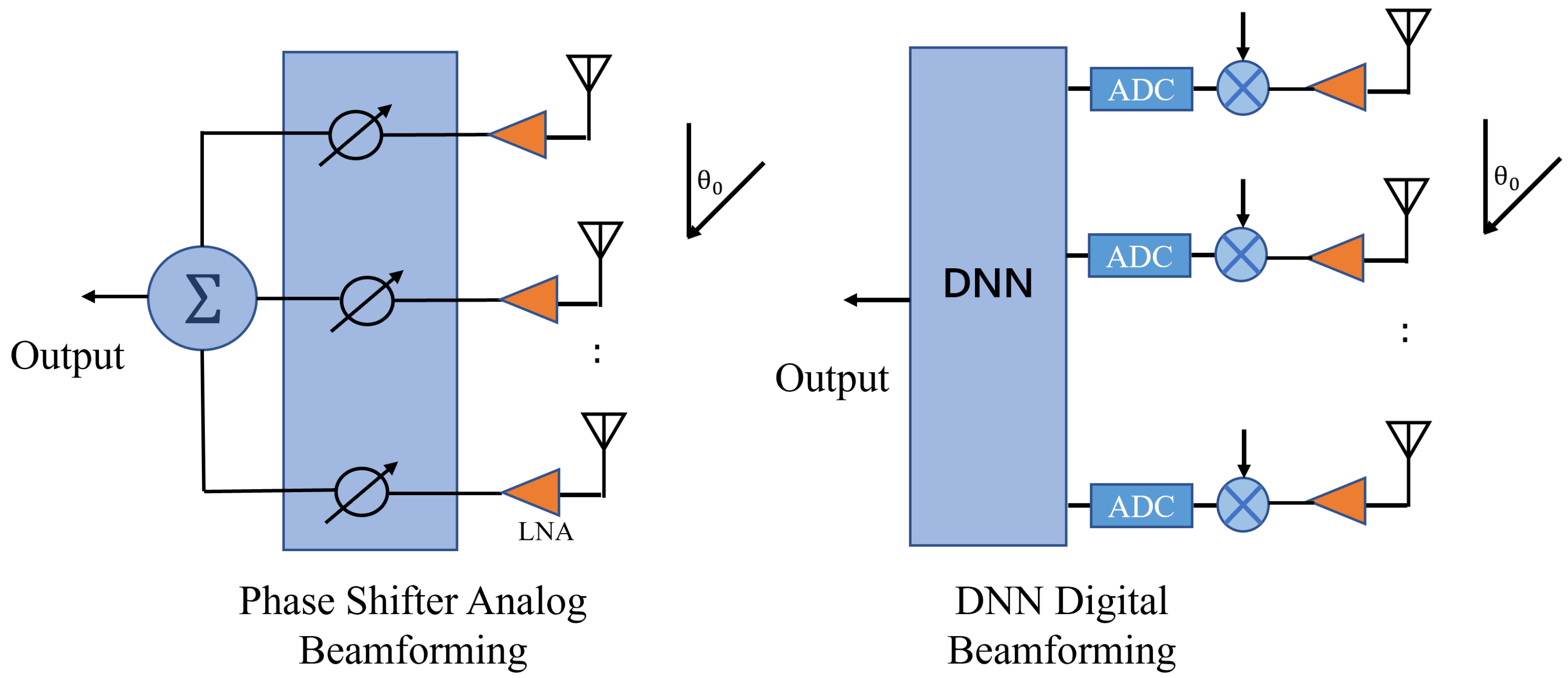
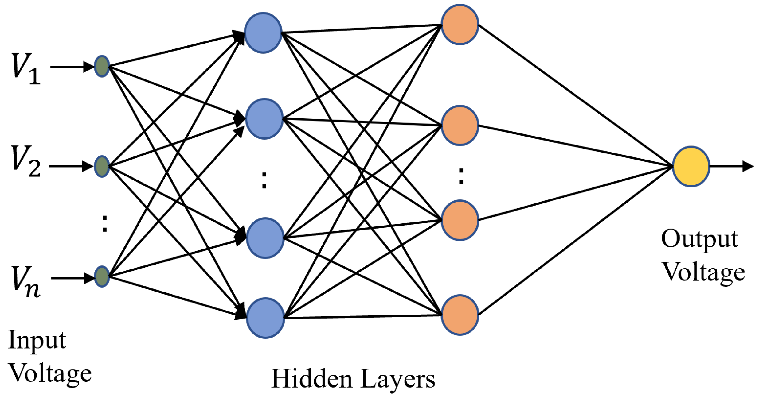
2. DNN Beamforming
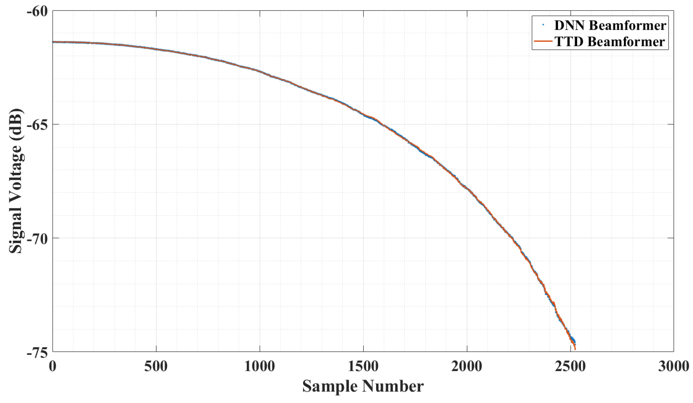
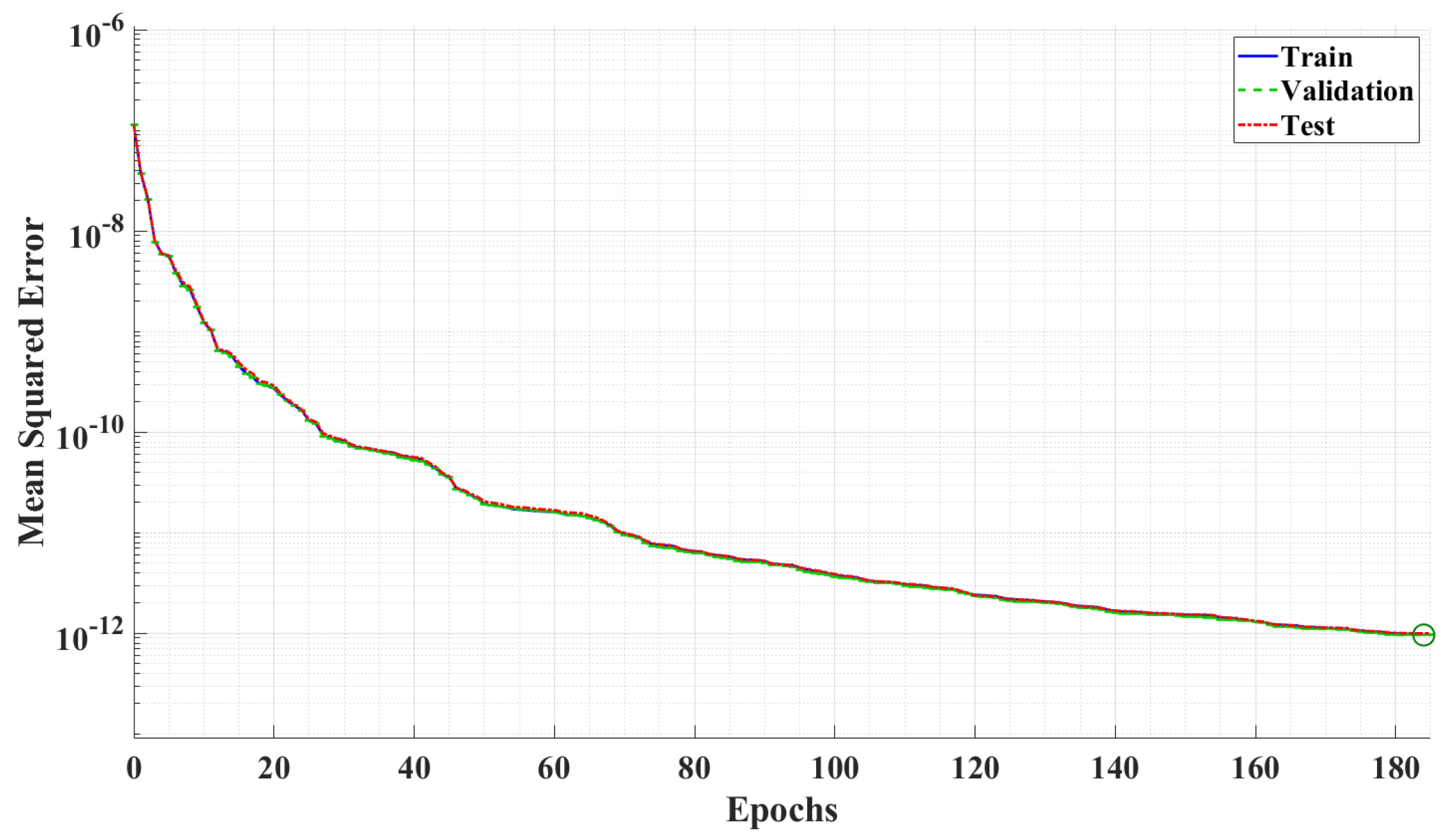
3. Numerical Results
4. Conclusions
Author Contributions
Funding
Acknowledgments
Conflicts of Interest
Appendix A

References
- Akyildiz, I.F.; Kak, A.; Nie, S. 6G and Beyond: The Future of Wireless Communications Systems. IEEE Access 2020, 8, 133995–134030. [Google Scholar] [CrossRef]
- Božanić, M.; Sinha, S. Getting Ready for Terahertz Electronics. In Millimeter-Wave Integrated Circuits: Methodologies for Research, Design and Innovation; Springer International Publishing: Cham, Switzerland, 2020. [Google Scholar] [CrossRef]
- 3GPP. 3GPP TR 38.811: Study on New Radio (NR) to Support Non-Terrestrial Networks. 2020. Available online: https://www.3gpp.org/ftp/Specs/archive/38_series/38.811/ (accessed on 26 October 2022).
- 3GPP. 3GPP TR 38.821: Solutions for NR to Support Non-Terrestrial Networks (NTN). 2021. Available online: https://www.3gpp.org/ftp/Specs/archive/38_series/38.821/ (accessed on 26 October 2022).
- 3GPP. 3GPP TR 36.763: Study on Narrow-Band Internet of Things (NB-IoT)/Enhanced Machine Type Communication (eMTC) Support for Non-Terrestrial Networks (NTN). 2021. Available online: https://www.3gpp.org/ftp/Specs/archive/36_series/36.763/ (accessed on 26 October 2022).
- Kim, M.G.; Jo, H.S. Performance Analysis of NB-IoT Uplink in Low Earth Orbit Non-Terrestrial Networks. Sensors 2022, 22, 7097. [Google Scholar] [CrossRef]
- Giordani, M.; Zorzi, M. Non-Terrestrial Networks in the 6G Era: Challenges and Opportunities. IEEE Netw. 2021, 35, 244–251. [Google Scholar] [CrossRef]
- Shi, X.; Liu, R.; Thompson, J.S. Novel distributed beamforming algorithms for heterogeneous space terrestrial integrated network. IEEE Internet Things J. 2021, 9, 11351–11364. [Google Scholar] [CrossRef]
- Lin, C.; Li, G.Y. Indoor Terahertz Communications: How Many Antenna Arrays Are Needed? IEEE Trans. Wirel. Commun. 2015, 14, 3097–3107. [Google Scholar] [CrossRef]
- Lialios, D.I.; Ntetsikas, N.; Paschaloudis, K.D.; Zekios, C.L.; Georgakopoulos, S.V.; Kyriacou, G.A. Design of True Time Delay Millimeter Wave Beamformers for 5G Multibeam Phased Arrays. Electronics 2020, 9, 1331. [Google Scholar] [CrossRef]
- Xiao, Z.; Han, Z.; Nallanathan, A.; Dobre, O.A.; Clerckx, B.; Choi, J.; He, C.; Tong, W. Antenna Array Enabled Space/Air/Ground Communications and Networking for 6G. IEEE J. Sel. Areas Commun. 2022, 40, 2773–2804. [Google Scholar] [CrossRef]
- Ikram, M.; Sultan, K.; Lateef, M.F.; Alqadami, A.S.M. A Road towards 6G Communication: A Review of 5G Antennas, Arrays, and Wearable Devices. Electronics 2022, 11, 169. [Google Scholar] [CrossRef]
- Dicandia, F.A.; Fonseca, N.J.G.; Bacco, M.; Mugnaini, S.; Genovesi, S. Space-Air-Ground Integrated 6G Wireless Communication Networks: A Review of Antenna Technologies and Application Scenarios. Sensors 2022, 22, 3136. [Google Scholar] [CrossRef]
- García Sánchez, M. Millimeter-Wave Communications. Electronics 2020, 9, 251. [Google Scholar] [CrossRef] [Green Version]
- Massaccesi, A.; Dassano, G.; Pirinoli, P. Beam Scanning Capabilities of a 3D-Printed Perforated Dielectric Transmitarray. Electronics 2019, 8, 379. [Google Scholar] [CrossRef] [Green Version]
- Amazon. Amazon’s Project Kuiper Satellites Will Fly on the New Vulcan Centaur Rocket in Early 2023. Available online: https://www.aboutamazon.com/news/innovation-at-amazon/amazons-project-kuiper-satellites-will-fly-on-the-new-vulcan-centaur-rocket-in-early-2023 (accessed on 26 October 2022).
- Rainbow, J. Lynk Global to Deploy Experimental 5G Payload in December. SpaceNews. Available online: https://spacenews.com/lynk-global-to-deploy-experimental-5g-payload-in-december/ (accessed on 26 October 2022).
- Pozdnyakov, A. iPhone 14 Will Have Satellite Connectivity. How Exactly It Will Work. Universe Today. Available online: https://www.universetoday.com/157474/iphone-14-will-have-satellite-connectivity-how-exactly-it-will-work/ (accessed on 26 October 2022).
- Liu, S.; Gao, Z.; Wu, Y.; Kwan Ng, D.W.; Gao, X.; Wong, K.K.; Chatzinotas, S.; Ottersten, B. LEO Satellite Constellations for 5G and Beyond: How Will They Reshape Vertical Domains? IEEE Commun. Mag. 2021, 59, 30–36. [Google Scholar] [CrossRef]
- Bailleul, P.K. A New Era in Elemental Digital Beamforming for Spaceborne Communications Phased Arrays. Proc. IEEE 2016, 104, 623–632. [Google Scholar] [CrossRef]
- Alzubaidi, O.T.H.; Hindia, M.N.; Dimyati, K.; Noordin, K.A.; Wahab, A.N.A.; Qamar, F.; Hassan, R. Interference Challenges and Management in B5G Network Design: A Comprehensive Review. Electronics 2022, 11, 2842. [Google Scholar] [CrossRef]
- Rappaport, T.S.; Xing, Y.; Kanhere, O.; Ju, S.; Madanayake, A.; Mandal, S.; Alkhateeb, A.; Trichopoulos, G.C. Wireless Communications and Applications Above 100 GHz: Opportunities and Challenges for 6G and Beyond. IEEE Access 2019, 7, 78729–78757. [Google Scholar] [CrossRef]
- Pirapaharan, K.; Ajithkumar, N.; Sarujan, K.; Fernando, X.; Hoole, P.R.P. Smart, Fast, and Low Memory Beam-Steering Antenna Configurations for 5G and Future Wireless Systems. Electronics 2022, 11, 2658. [Google Scholar] [CrossRef]
- Kumar, R.; Arnon, S. SNR Optimization for LEO Satellite at sub-THz Frequencies. IEEE Trans. Antennas Propag. 2022, 70, 4449–4458. [Google Scholar] [CrossRef]
- Spoof, K.; Unnikrishnan, V.; Zahra, M.; Stadius, K.; Kosunen, M.; Ryynänen, J. True-Time-Delay Beamforming Receiver with RF Re-Sampling. IEEE Trans. Circuits Syst. I Regul. Pap. 2020, 67, 4457–4469. [Google Scholar] [CrossRef]
- Rotman, R.; Tur, M.; Yaron, L. True Time Delay in Phased Arrays. Proc. IEEE 2016, 104, 504–518. [Google Scholar] [CrossRef]
- Yang, G.; Zhang, Y.; Zhang, S. Wide-Band and Wide-Angle Scanning Phased Array Antenna for Mobile Communication System. IEEE Open J. Antennas Propag. 2021, 2, 203–212. [Google Scholar] [CrossRef]
- Toledo, P.; Rubino, R.; Musolino, F.; Crovetti, P. Re-Thinking Analog Integrated Circuits in Digital Terms: A New Design Concept for the IoT Era. IEEE Trans. Circuits Syst. II Express Briefs 2021, 68, 816–822. [Google Scholar] [CrossRef]
- Yang, B.; Yu, Z.; Lan, J.; Zhang, R.; Zhou, J.; Hong, W. Digital Beamforming-Based Massive MIMO Transceiver for 5G Millimeter-Wave Communications. IEEE Trans. Microw. Theory Tech. 2018, 66, 3403–3418. [Google Scholar] [CrossRef]
- Peter, D.; Broughton, B.; Kraft, J. Phased Array Antenna Patterns—Part 2: Grating Lobes and Beam Squint. 2020. Available online: https://www.analog.com/en/analog-dialogue/articles/phased-array-antenna-patterns-part2.html (accessed on 26 October 2022).
- Tanveer, J.; Haider, A.; Ali, R.; Kim, A. Machine Learning for Physical Layer in 5G and beyond Wireless Networks: A Survey. Electronics 2022, 11, 121. [Google Scholar] [CrossRef]
- Luo, F.L.; Unbehauen, R. Applied Neural Networks for Signal Processing; Cambridge University Press: Cambridge, UK, 1998. [Google Scholar]
- Rekkas, V.P.; Sotiroudis, S.; Sarigiannidis, P.; Wan, S.; Karagiannidis, G.K.; Goudos, S.K. Machine Learning in Beyond 5G/6G Networks—State-of-the-Art and Future Trends. Electronics 2021, 10, 2786. [Google Scholar] [CrossRef]
- Luo, F.L.; Zhang, C.J. Signal Processing for 5G: Algorithms and Implementations; John Wiley & Sons: Hoboken, NJ, USA, 2016. [Google Scholar]
- Dong, X.; Thanou, D.; Toni, L.; Bronstein, M.; Frossard, P. Graph Signal Processing for Machine Learning: A Review and New Perspectives. IEEE Signal Process. Mag. 2020, 37, 117–127. [Google Scholar] [CrossRef]
- Jagannath, A.; Jagannath, J.; Melodia, T. Redefining Wireless Communication for 6G: Signal Processing Meets Deep Learning with Deep Unfolding. IEEE Trans. Artif. Intell. 2021, 2, 528–536. [Google Scholar] [CrossRef]
- Ortiz-Gomez, F.G.; Lei, L.; Lagunas, E.; Martinez, R.; Tarchi, D.; Querol, J.; Salas-Natera, M.A.; Chatzinotas, S. Machine Learning for Radio Resource Management in Multibeam GEO Satellite Systems. Electronics 2022, 11, 992. [Google Scholar] [CrossRef]
- Zhang, T.; Dong, A.; Zhang, C.; Yu, J.; Qiu, J.; Li, S.; Zhou, Y. Hybrid Beamforming for MISO System via Convolutional Neural Network. Electronics 2022, 11, 2213. [Google Scholar] [CrossRef]
- Xia, W.; Zheng, G.; Zhu, Y.; Zhang, J.; Wang, J.; Petropulu, A.P. A Deep Learning Framework for Optimization of MISO Downlink Beamforming. IEEE Trans. Commun. 2020, 68, 1866–1880. [Google Scholar] [CrossRef]
- Alkhateeb, A.; Alex, S.; Varkey, P.; Li, Y.; Qu, Q.; Tujkovic, D. Deep Learning Coordinated Beamforming for Highly-Mobile Millimeter Wave Systems. IEEE Access 2018, 6, 37328–37348. [Google Scholar] [CrossRef]
- Li, W.; Huang, X.; Leung, H. Performance evaluation of digital beamforming strategies for satellite communications. IEEE Trans. Aerosp. Electron. Syst. 2004, 40, 12–26. [Google Scholar] [CrossRef]
- ITU. ITU Recommendation P. 676-12: Attenuation by Atmospheric Gases and Related Effects. 2019. Available online: https://www.itu.int/rec/R-REC-P.676 (accessed on 26 October 2022).
- Silvestrini, S.; Lavagna, M. Deep Learning and Artificial Neural Networks for Spacecraft Dynamics, Navigation and Control. Drones 2022, 6, 270. [Google Scholar] [CrossRef]
- Gao, J.; Zhong, C.; Li, G.Y.; Zhang, Z. Online Deep Neural Network for Optimization in Wireless Communications. IEEE Wirel. Commun. Lett. 2022, 11, 933–937. [Google Scholar] [CrossRef]
- ITU. ITU Recommendation P. 835-6: Reference Standard Atmospheres. 2017. Available online: https://www.itu.int/rec/R-REC-P.835/_page.print (accessed on 26 October 2022).
- Williams, C.R. How Much Attenuation Extinguishes mm-Wave Vertically Pointing Radar Return Signals? Remote Sens. 2022, 14, 1305. [Google Scholar] [CrossRef]
- del Portillo, I.; Cameron, B.G.; Crawley, E.F. A technical comparison of three low earth orbit satellite constellation systems to provide global broadband. Acta Astronaut. 2019, 159, 123–135. [Google Scholar] [CrossRef]
- Tansri, K.; Chansangiam, P. Conjugate Gradient Algorithm for Least-Squares Solutions of a Generalized Sylvester-Transpose Matrix Equation. Symmetry 2022, 14, 1868. [Google Scholar] [CrossRef]
- Zhu, H.; Leandro, J.; Lin, Q. Optimization of Artificial Neural Network (ANN) for Maximum Flood Inundation Forecasts. Water 2021, 13, 2252. [Google Scholar] [CrossRef]
- Kumar, R.; Arnon, S. Enhancing Cybersecurity of Satellites at Sub-THz Bands. In Cyber Security, Cryptology, and Machine Learning; Dolev, S., Katz, J., Meisels, A., Eds.; Springer International Publishing: Cham, Switzerland, 2022; pp. 356–365. [Google Scholar]
- Deng, R.; Di, B.; Zhang, H.; Kuang, L.; Song, L. Ultra-Dense LEO Satellite Constellations: How Many LEO Satellites Do We Need? IEEE Trans. Wirel. Commun. 2021, 20, 4843–4857. [Google Scholar] [CrossRef]


| Definition | Symbol | Value |
|---|---|---|
| Transmitter power | 2 W | |
| Transmitter antenna diameter | 3 m | |
| Satellite altitude | 1000 km | |
| Atmospheric height | 100 km | |
| Number of array elements | N | 1000 |
| Antenna efficiency | 0.9 | |
| Center frequency | 100 GHz | |
| Antenna spacing at | d | |
| Bandwidth | B | 2 GHz |
Publisher’s Note: MDPI stays neutral with regard to jurisdictional claims in published maps and institutional affiliations. |
© 2022 by the authors. Licensee MDPI, Basel, Switzerland. This article is an open access article distributed under the terms and conditions of the Creative Commons Attribution (CC BY) license (https://creativecommons.org/licenses/by/4.0/).
Share and Cite
Kumar, R.; Arnon, S. DNN Beamforming for LEO Satellite Communication at Sub-THz Bands. Electronics 2022, 11, 3937. https://doi.org/10.3390/electronics11233937
Kumar R, Arnon S. DNN Beamforming for LEO Satellite Communication at Sub-THz Bands. Electronics. 2022; 11(23):3937. https://doi.org/10.3390/electronics11233937
Chicago/Turabian StyleKumar, Rajnish, and Shlomi Arnon. 2022. "DNN Beamforming for LEO Satellite Communication at Sub-THz Bands" Electronics 11, no. 23: 3937. https://doi.org/10.3390/electronics11233937