Article

Simultaneous Beam Forming and Focusing Using a Checkerboard Anisotropic Surface

1
Department of Convergence IT Engineering, Kyungnam University, Changwon 51767, Korea
2
Department of Electronic Engineering, Kyungnam University, Changwon 51767, Korea
*
Author to whom correspondence should be addressed.
Electronics 2022, 11(22), 3823; https://doi.org/10.3390/electronics11223823
Submission received: 17 October 2022 / Revised: 11 November 2022 / Accepted: 16 November 2022 / Published: 21 November 2022
(This article belongs to the Section Microwave and Wireless Communications)

Abstract

:
A novel design method of simultaneous beam forming and focusing using a checkerboard anisotropic surface is proposed and verified in this paper. The proposed multibeam control regardless of far and near regions can easily be achieved through a rearrangement of the checkerboard structure. The unit cell of the utilized anisotropic surface consists of two identical metallic structures divided by a dielectric material. When the EM wave with a circular polarization (CP) is incident on the unit cell, the maximum transmission phase variation of the unit cell is 360 degrees by half rotation of the unit cell. A microstrip patch antenna with trimmed corners is used to launch the CP wave and the distance between the microstrip patch antenna and anisotropic surface is about 2 wavelengths considering the optimized spillover and taper efficiencies. After designing each anisotropic surface for beam forming and focusing, the unit cells of the surface are rearranged in the form of a checkerboard. The feasibility of the proposed method is confirmed by full-wave simulation and measurement for anisotropic surface with a beam forming angle of 30 degrees and beam focusing point 60 mm away from center at 5.8 GHz. The forming angle and focal length are simulated and measured to be 28 degrees and about 65 mm, respectively.

1. Introduction

Wireless power transfer (WPT) is the technology to transmit power without a direct connection such as cables [1,2,3,4,5]. Thus, the WPT is very useful and applicable technology in various areas. Since 5G and 6G wireless networks will especially accelerate the growth of the IoT by providing faster data transfer speeds, the WPT using a microwave, which is advantageous for long-distance power transmission, will be more needed to charge IoT devices [6,7,8,9,10,11,12,13,14]. The beam steering and multi beam forming should be achieved to charge multi-target simultaneously in the WPT system using a microwave [6,7]. In [11], to obtain the characteristic of multi beam forming, the incident input amplitudes and phases at the metasurface are computed by numerical optimization. The WPT to charge the multi-target at 5.8 GHz is verified using sequential phase ring antenna and inverted class F rectenna experimentally [13].
In order to transfer power to the multiple IoT devices simultaneously, the WPT system using a microwave must have a multi-beam control function. In particular, when the devices that need to charge are located in both far and near field regions, the function to simultaneously steer and focus the beam is needed to the WPT system. Various studies have been researched and published in recent years [15,16,17]. WPT to various devices using the array antenna can be implemented more efficiently by considering the weights that have to be applied to the array elements [15]. In [17], the required phase of each cell of frequency selective surface (FSS) for simultaneous beam forming and focusing are calculated mathematically by the principle of superposition.
Recently, the beam steering and focusing techniques using the metasurface have been researched intensively [18,19,20,21,22,23]. In this paper, a novel design methodology of simultaneous beam forming and focusing by a rearrangement of anisotropic surface in the form of a checkerboard is proposed. Multibeam control regardless of far and near regions easily can be achieved through a structural rearrangement. A single-layer anisotropic surface is designed using an electric field coupled resonators (ELCRs) [24]. If a circularly polarized (CP) wave is incident on the unit cell of the surface, the transmitted phase variation of the unit cell is twice the rotation angle of the unit cell. In this paper, the source antenna has the operation frequency of 5.8 GHz and a right-handed (RH) CP characteristic. In the next section, the operation principle of the unit cell of the anisotropic surface is explained, and the full-wave simulated results are presented. The design procedure and measured results of the transmit array antenna for simultaneous beam forming and focusing are discussed in Section 3. In the final section, the concluding remarks are given.

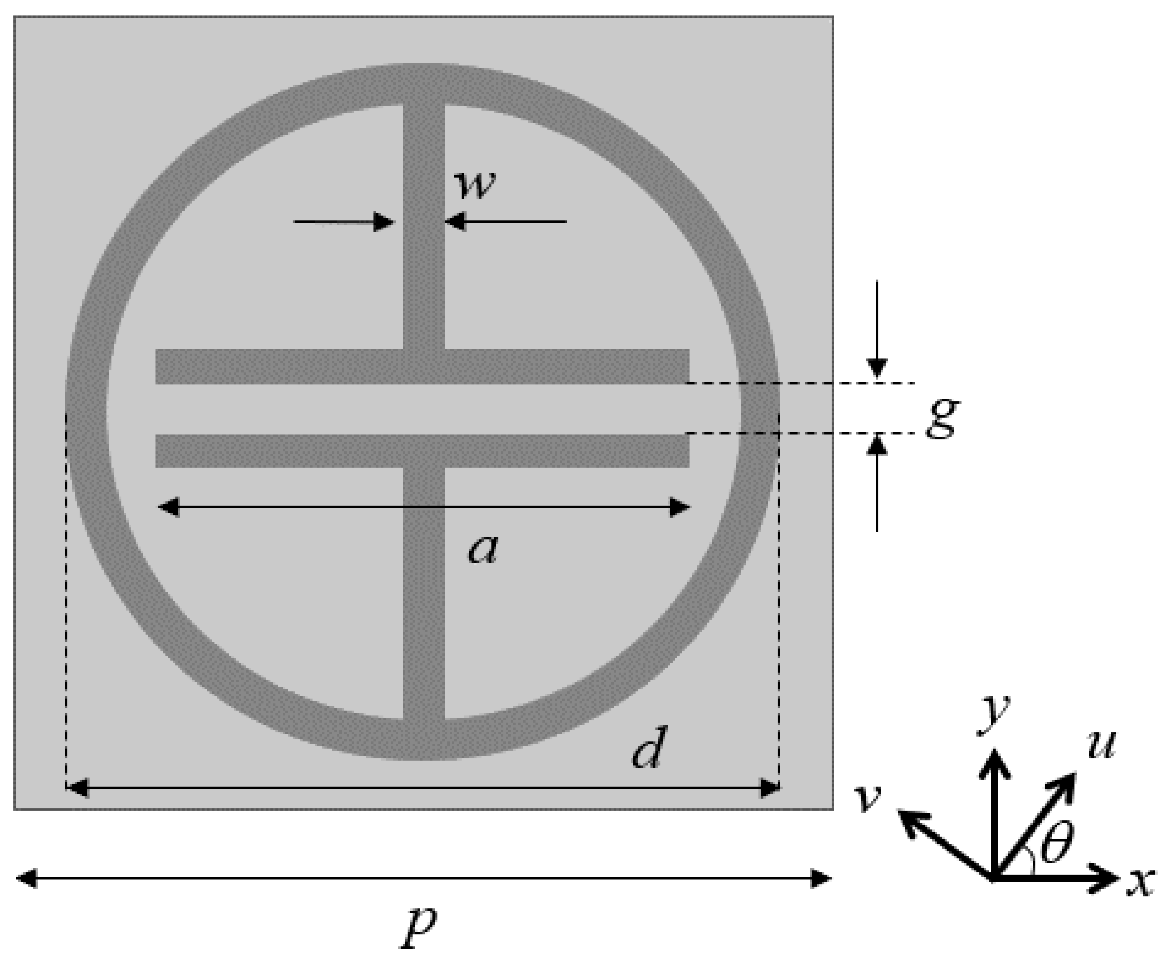
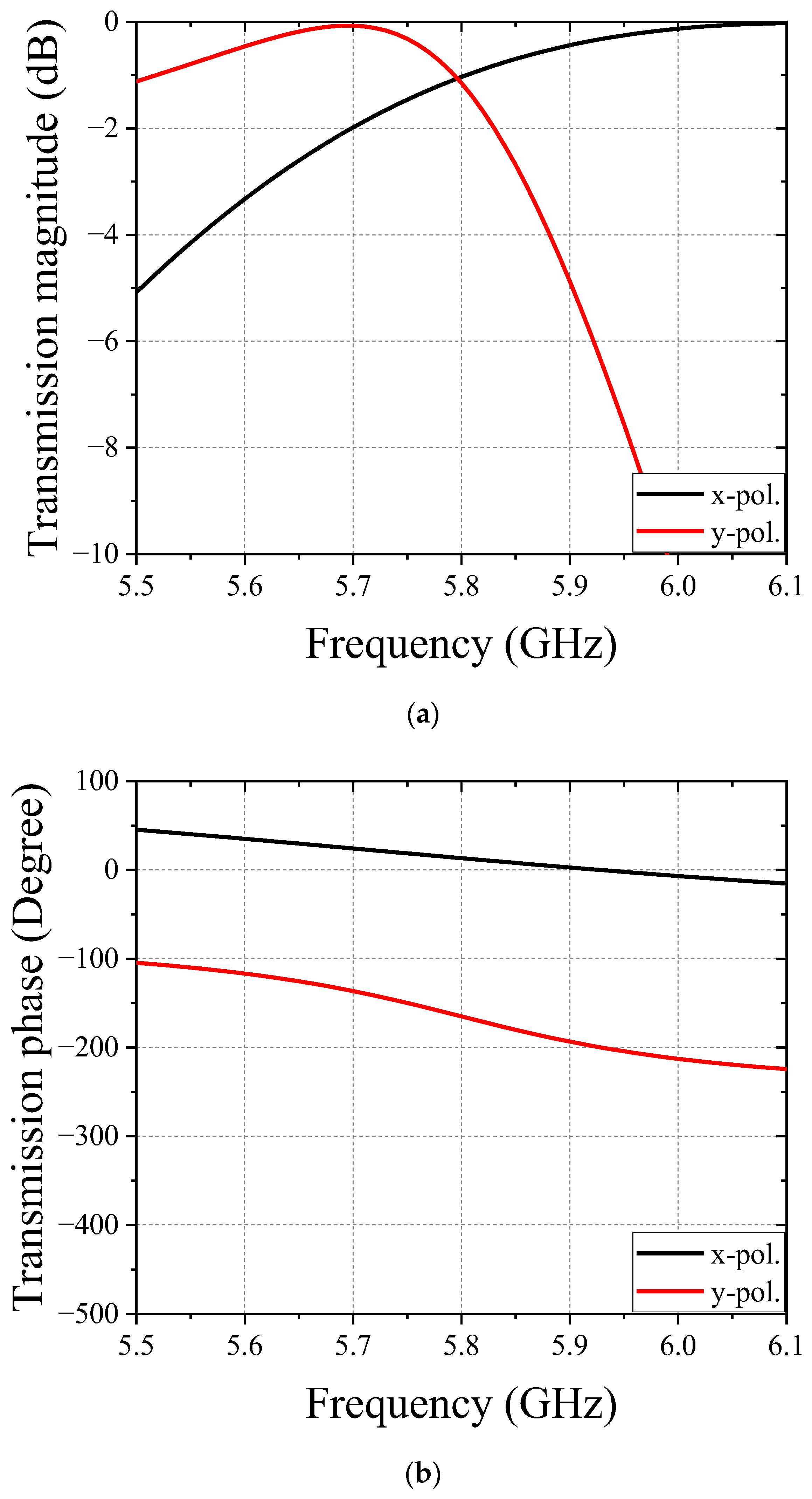
2. Design of Unit Cell of Anisotropic Surface

Two identical electric field coupled resonators (ELCRs) of Figure 1 are utilized to design the unit cell of anisotropic surface in this paper. The unit cell consists of two metallic layers and one dielectric material. The metal structure has a circle ring shape for an inductance with a gap-coupled line for a shunt capacitance. When CP wave is incident on the anisotropic surface, the designed surface can control the transmitted wave-front through the surface by the spin of the unit cell. When the two-metal structure is rotated by the same θ, the rotated coordinate can be expressed as
x = u c o s θ v s i n θ ,   y = u s i n θ v c o s θ
If the two orthogonally polarized transmission coefficients are equal in magnitude while opposite in phase, the transmitted wave has a characteristic of LHCP with a transmitted phase of 2θ in case of incidence of RHCP wave. The dimensions of the unit cell for operation frequency of 5.8 GHz are set as p = 20 mm, d = 17.26 mm, a = 11.83 mm, g = 1 mm, w = 1 mm. The unit cell for anisotropic surface is made of RT/duroid 5880 with a relative permittivity of 2.2 and a thickness of 3.2 mm. At the frequency of 5.8 GHz, the two orthogonally polarized transmission coefficients are simulated with the same magnitude of −1.1 dB and opposite phase by ANSYS Electronics desktop software, as shown in Figure 2.

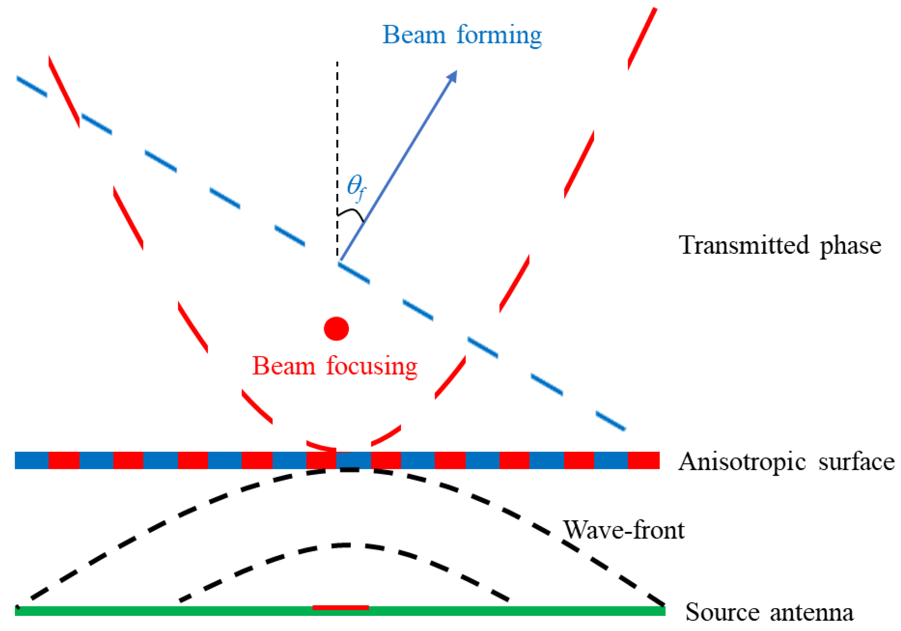
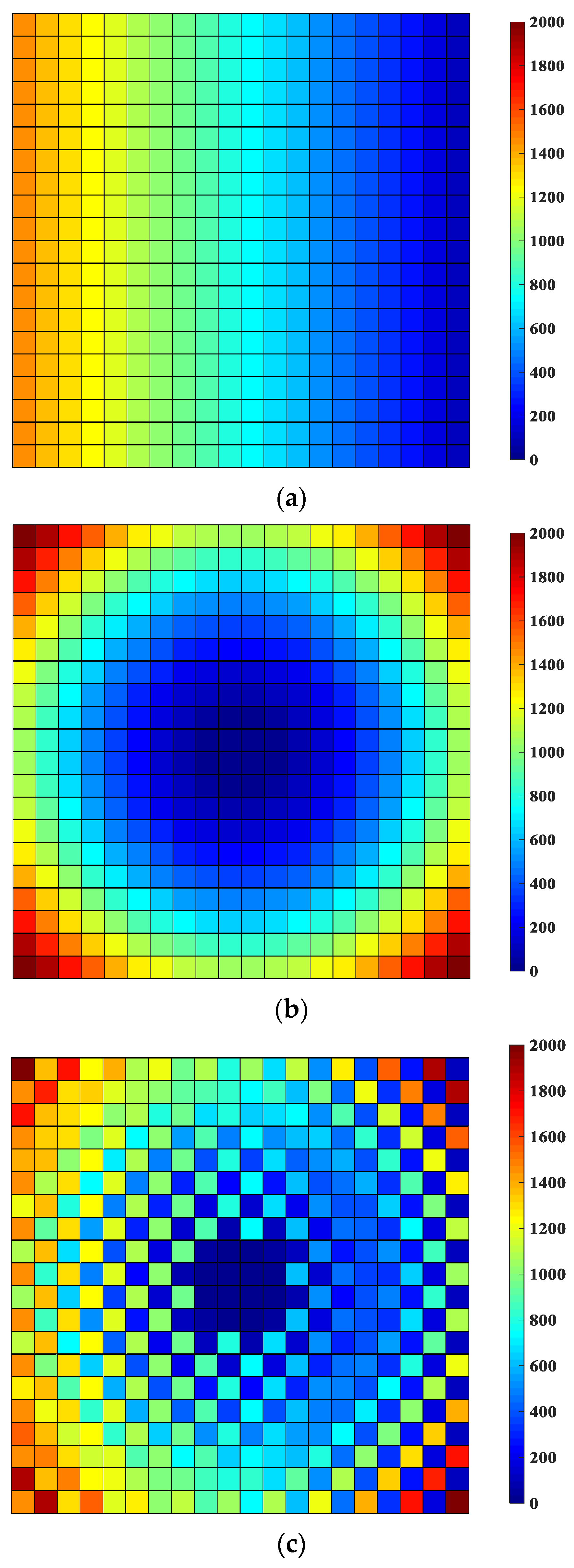
3. Design and Results of Simultaneous Beam Forming and Focusing

The beam forming angle can be decided if the phase differences (ϕ) are equal to the propagation induced phase delays, namely ϕ = βp × sinθf. Additionally, the beam focusing can be implemented using parabola formula. In order to realize the focal length (f), the phase of the transmitted wave should satisfy the following equation
φ ( x , y ) = 2 π λ ( x 2 + y 2 + f 2 f )
where λ is wavelength of the operating frequency. x and y are the horizontal and vertical axes of anisotropic surface, respectively. Figure 3 shows the relation between beam and transmitted phase through anisotropic surface. The designed anisotropic surface can manipulate the wave-front of the source antenna with CP characteristic. The simultaneous beam forming and focusing can be achieved by a checkerboard anisotropic surface, as shown in Figure 3. The wave-front and anisotropic surface for beam forming are plotted by a blue line. Similarly, the wave-front and anisotropic surface for beam focusing are plotted by a red line. In this paper, the total area of the anisotropic surface having unit cells of 20 × 20 is 400 mm × 400 mm. The feasibility of the proposed methodology is confirmed by simulated and measured results of the transmitarray antenna with beam forming angle of 30 degrees and beam focusing point 60 mm away from center at 5.8 GHz. To achieve beam forming and focusing at the desired direction, the shape of the transmission phase using an active metasurface should be controlled. First, we have calculated the transmission phase of the unit cell of the anisotropic surface for beam forming by ϕ = βp × sinθf. Next, we have decided the transmission phase of unit cell of anisotropic surface for beam focusing by Equation (2). By the design principle of the anisotropic surface that can have twice the transmission phase of the rotation angle of unit cell, the unit cell corresponding to the calculated phase for beamforming and beam focusing is arranged. After designing each anisotropic surface for beam forming and focusing, the unit cells of the surface are rearranged in the form of checkerboard. Figure 4 shows the full-wave simulated transmission phases of anisotropic surface for each beam forming and beam focusing, and simultaneous beam forming and focusing. As the number of unit cells is an even number, the 4 × 4 cells in the center are arranged as unit cells for beam focusing to obtain the symmetric shape of beam focusing, as shown in Figure 4c. Figure 5 shows the photographs of fabricated transmitarray antenna consists of source antenna and anisotropic surface. To launch an RHCP wave, a CP microstrip patch antenna with trimmed corners is utilized, as shown in Figure 5a. The dimensions of the patch antenna are 16.5 mm (Length) and 16 mm (Width). Truncation of 2.8 mm in length and 2.8 mm in width of rectangular patch has been implemented at two opposite corners. A coaxial cable feeding is employed and is located 3.25 mm from the center. In addition, the thickness and the relative permittivity of the substrate (RT/duroid 5880) for source antenna are 1.6 mm and 2.2, respectively.
The distance between source antenna and anisotropic surface is considered to be 100 mm (≈2λ0 at 5.8 GHz) considering optimized spillover and taper efficiencies. Thus, the overall dimension of the fabricated transmitarray antenna is 400 mm (Length) × 400 mm (Width) × 104.8 mm (Height). The forming angle and focal length are simulated to be 28 degrees and 64.8 mm having errors of about 7% and 8% by FEM simulator (ANSYS Electronics desktop software), respectively. The simulated electric field intensity is obtained along the x-axis at focal length of 64.8 mm, as shown in Figure 6a. Additionally, to measure the electric field intensity, the receiving LHCP patch antenna is placed on the Styrofoam and S21 is measured on the x-axis (z = 64 mm) at intervals of 10 mm, as shown in Figure 6b. Additionally, the measured far-field radiation pattern is obtained using the semi-anechoic chamber system. The semi-anechoic chamber can suppress the multiple reflections using three 18-inch pyramidal absorbers and the time gating process of the vector network analyzer. As shown in Figure 7, the measured results agree well with the analytic and the full-wave simulated results. A slight difference between analytic and measured results is caused by the finite dimension of anisotropic surface and relatively large unit cell for the wavelength.

4. Conclusions

In this paper, simultaneous beam forming and focusing is implemented through a checkerboard anisotropic surface. After designing each anisotropic surface for beam forming and focusing, the unit cells of surface are rearranged in the checkerboard pattern. Therefore, multibeam control regardless of far and near regions can easily be achieved through a structural rearrangement. The feasibility of the proposed method is confirmed by a full-wave simulation and measurements for an anisotropic surface with beam forming angle of 30 degrees and beam focusing point 60 mm away from center at 5.8 GHz. The measurement results are in good agreement with the analytic and simulation results. The forming angle and focal length are simulated and measured to be about 30 degrees and about 65 mm having errors of about 7% and 8%, respectively. This study successfully demonstrates that the designed transmitarray antenna generates simultaneous beam forming and focusing.

Author Contributions

Conceptualization, J.-G.L.; methodology, J.-G.L.; software, J.-H.P.; validation, J.-G.L.; formal analysis, J.-G.L.; investigation, J.-H.P.; resources, J.-H.P.; writing—original draft preparation, J.-H.P.; writing—review and editing, J.-G.L.; visualization, J.-H.P.; supervision, J.-G.L.; project administration, J.-G.L.; funding acquisition, J.-G.L. All authors have read and agreed to the published version of the manuscript.

Funding

This work was supported by the National Research Foundation of Korea (NRF) grant funded by the Korea government (MSIT) (No. 2020R1F1A1051217) and was supported by the MSIT (Ministry of Science and ICT), Korea, under the Innovative Human Resource Development for Local Intellectualization support program (IITP-2022-RS-2022-00156361) supervised by the IITP (Institute for Information & communications Technology Planning & Evaluation).

Conflicts of Interest

The authors declare no conflict of interest.

References

  1. Tesla, N. Apparatus for Transmitting Electrical Energy. U.S. Patent 1,119,732, 1 December 1914. [Google Scholar]
  2. Kurs, A.; Karalis, A.; Moffatt, R.; Joannopoulos, J.D.; Fisher, P.; Soljacic, M. Wireless power transfer via strongly coupled magnetic resonances. Science 2007, 317, 83–86. [Google Scholar] [CrossRef] [Green Version]
  3. Esser, A.; Skudelny, H.C. A new approach to power supplies for robots. IEEE Trans. Ind. Appl. 1991, 27, 872–875. [Google Scholar] [CrossRef]
  4. Hirai, J.; Kim, T.W.; Kawamura, A. Wireless transmission of power and information for cableless linear motor drive. IEEE Trans. Power Electron. 2000, 15, 21–27. [Google Scholar] [CrossRef]
  5. Shan, D.; Wang, H.; Cao, K.; Zhang, J. Wireless power transfer system with enhanced efficiency by using frequency reconfigurable metamaterial. Sci. Rep. 2022, 12, 331. [Google Scholar] [CrossRef]
  6. Ku, M.L.; Han, Y.; Wang, B.; Liu, K.R. Joint power waveforming and beamforming for wireless power transfer. IEEE Trans. Signal Process 2017, 65, 6409–6422. [Google Scholar] [CrossRef]
  7. Yedavalli, P.S.; Riihonen, T.; Wang, X.; Rabaey, J.M. Far-field RF wireless power transfer with blind adaptive beamforming for Internet of Things devices. IEEE Access 2017, 5, 1743–1752. [Google Scholar] [CrossRef]
  8. Brown, W.C. The history of power transmission by radio waves. IEEE Trans. Microw. Theory Tech. 1984, 32, 1230–1242. [Google Scholar] [CrossRef] [Green Version]
  9. Shinohara, N. History and innovation of wireless power transfer via microwaves. IEEE J. Microw. 2021, 1, 218–228. [Google Scholar] [CrossRef]
  10. Song, C.; Huang, Y.; Zhou, J.; Carter, P.; Yuan, S.; Xu, Q.; Fei, Z. Matching network elimination in broadband rectennas for high-efficiency wireless power transfer and energy harvesting. IEEE Trans. Ind. Electron. 2017, 64, 3950–3961. [Google Scholar] [CrossRef] [Green Version]
  11. Xu, H.X.; Cai, T.; Zhuang, Y.Q.; Peng, Q.; Wang, G.; Liang, J.G. Dual-Mode transmissive metasurface and its applications in multibeam transmitarray. IEEE Trans. Antennas Propag. 2017, 65, 1797–1806. [Google Scholar] [CrossRef]
  12. Hu, B.; Li, H.; Li, T.; Wang, H.; Zhou, Y.; Zhao, X.; Hu, X.; Du, X.; Zhao, Y.; Li, X.; et al. A long-distance high-power microwave wireless power transmission system based on asymmetrical resonant magnetron and cyclotron-wave rectifier. Energy Rep. 2021, 7, 1154–1161. [Google Scholar] [CrossRef]
  13. Nguyen, D.M.; Au, N.D.; Seo, C. A microwave power transmission system using sequential phase ring antenna and inverted class F rectenna. IEEE Access 2021, 9, 134163–134173. [Google Scholar] [CrossRef]
  14. Park, I.; Ku, H. Multiple beamforming using multi-tone signals for microwave power transfer system. IEEE Trans. Microw. Theory Tech. 2021, 70, 1975–1982. [Google Scholar] [CrossRef]
  15. Ayestarán, R.G.; León, G.; Pino, M.R.; Nepa, P. Wireless power transfer through simultaneous near-field focusing and far-field synthesis. IEEE Trans. Antennas Propag. 2019, 67, 5623–5633. [Google Scholar] [CrossRef]
  16. Qu, S.W.; Yi, H.; Chen, B.; Ng, K.B.; Chan, C.H. Terahertz reflecting and transmitting metasurfaces. Proc. IEEE 2017, 105, 1166–1184. [Google Scholar] [CrossRef]
  17. Lee, C.H.; Lee, J.H. Non-uniform amplitude transmitarray for multi-beam including near-field focusing. IEEE Trans. Antennas Propag. 2021. early access. [Google Scholar] [CrossRef]
  18. Park, J.H.; Lee, J.G. 2-D beam focusing control based on passive frequency selective surface (FSS). Electronics 2021, 10, 1938. [Google Scholar] [CrossRef]
  19. Wang, M.; Xu, S.; Yang, F.; Hu, N.; Xie, W.; Chen, Z. A novel 1-bit reconfigurable transmitarray antenna using a C-shaped probe-fed patch element with broadened bandwidth and enhanced efficiency. IEEE Access 2020, 8, 120124–120133. [Google Scholar] [CrossRef]
  20. Lee, J.G.; Kwon, T.S.; Lee, J.H. Beam pattern reconfigurable circularly polarized transmitarray antenna by rearrangement of sources. Microw. Opt. Technol. Lett. 2019, 61, 999–1003. [Google Scholar] [CrossRef]
  21. Diaby, F.; Clemente, A.; Sauleau, R.; Pham, K.T.; Dussopt, L. 2-bit reconfigurable unit-cell and electronically steerable transmitarray at Ka-band. IEEE Trans. Antennas Propag. 2020, 68, 5003–5008. [Google Scholar] [CrossRef]
  22. Lee, C.H.; Hoang, T.V.; Chi, S.W.; Lee, S.G.; Lee, J.H. Low profile quad-beam circularly polarized antenna using transmissive metasurface. IET Microw. Antennas Propag. 2019, 13, 1690–1698. [Google Scholar] [CrossRef]
  23. Wang, Y.; Xu, S.; Yang, F.; Li, M. A novel 1 bit wide-angle beam scanning reconfigurable transmitarray antenna using an equivalent magnetic dipole element. IEEE Trans. Antennas Propag. 2020, 68, 5691–5695. [Google Scholar] [CrossRef]
  24. Li, T.J.; Liang, J.G.; Li, H.P.; Liu, Y.Q. Ultra-thin single-layer transparent geometrical phase gradient metasurface and its application to high-gain circularly-polarized lens antenna. Chin. Phys. B 2016, 25, 094101. [Google Scholar] [CrossRef]
Figure 1. Unit cell of the metasurface (Top view).
Electronics 11 03823 g001
Figure 2. Full-wave simulated transmission responses of the unit cell of anisotropic surface. (a) Magnitude (b) Phase.
Electronics 11 03823 g002
Figure 3. Relation between beam and transmitted phase through anisotropic surface.
Electronics 11 03823 g003
Figure 4. Full-wave simulated transmission phases of anisotropic surface. (a) Beam forming of 30 degrees (b) Beam focusing (Focal length = 60 mm) (c) Simultaneous beam forming and focusing.
Electronics 11 03823 g004
Figure 5. Photographs of fabricated transmitarray antenna. (a) source antenna (b) Anisotropic antenna (c) Transmitarray antenna.
Electronics 11 03823 g005aElectronics 11 03823 g005b
Figure 6. Simulation and experiment setup for verification of beam focusing. (a) Simulation (b) Experiment.
Electronics 11 03823 g006
Figure 7. Performance of proposed antenna in far and near regions. (a) Far-field radiation pattern (ϕ = 0°) (b) Normalized E-field intensity at x-axis.
Electronics 11 03823 g007
Publisher’s Note: MDPI stays neutral with regard to jurisdictional claims in published maps and institutional affiliations.

