Article

Fault Diagnosis Method for an Underwater Thruster, Based on Load Feature Extraction

1
Logistics Engineering College, Shanghai Maritime University, Shanghai 201306, China
2
School of Mechanical Engineering, University of Shanghai for Science and Technology, Shanghai 200093, China
*
Author to whom correspondence should be addressed.
Electronics 2022, 11(22), 3714; https://doi.org/10.3390/electronics11223714
Submission received: 11 October 2022 / Revised: 11 November 2022 / Accepted: 11 November 2022 / Published: 13 November 2022

Abstract

:
Targeting the problem of fault diagnosis in magnetic coupling underwater thrusters, a fault pattern classification method based on load feature extraction is proposed in this paper. By analyzing the output load characteristics of thrusters under typical fault patterns, the load torque model of the thrusters is established, and two characteristic parameters are constructed to describe the different fault patterns of thrusters. Then, a thruster load torque reconstruction method, based on the sliding mode observer (SMO), and the fault characteristic parameter identification method, based on the least square method (LSM), are proposed. According to the identified fault characteristic parameters, a thruster fault pattern classification method based on a support vector machine (SVM) is proposed. Finally, the feasibility and superiority of the proposed aspects are verified, through comparative simulation experiments. The results show that the diagnostic accuracy of this method is higher than 95% within 5 seconds of the thruster fault. The lowest diagnostic accuracy of thrusters with a single failure state is 96.75%, and the average diagnostic accuracy of thrusters with five fault states is 98.65%.

1. Introduction

Underwater robots play an increasingly important role in tasks such as marine resource exploration and deep-sea operations [1,2]. As the power component of the underwater robot, the thruster is the key to controlling the motion of the machine. When the thruster fails, the thrust will be derated, or the power may even be lost. In extreme cases, this will also risk the loss of the underwater robot [3]. Fault diagnosis can detect the problem with the thruster in good time and enable the taking of rescue measures to prevent the further deterioration of the fault, thereby avoiding greater losses. Therefore, the fault diagnosis of thrusters is of great significance in the field of underwater robots.
In recent years, both domestic and foreign scholars have conducted extensive and in-depth research on thruster fault diagnosis methods. Chen et al. summarized the current research status of thruster fault diagnosis and divided the thruster fault diagnosis methods into three categories: the qualitative analysis diagnosis method, the signal processing diagnosis method, and the analytical model diagnosis method [4].
The diagnostic method of qualitative analysis is based on the operating mechanism of the system and infers the fault, according to the causal relationship of the fault. Common fault diagnosis methods include fault trees [5], directed graphs [6], and so on. Li et al. proposed a method combining the fault tree and the Monte Carlo method, established an underwater unmanned vehicle system model, obtained the minimum cut set of the fault tree, and combined the results with the Monte Carlo method for reliability verification [7]. Zhang et al. proposed a thruster fault diagnosis method, based on gray qualitative constrained filtering, to solve the problem of forgery behavior in a qualitative simulation of the model, and verified the effectiveness of the method through comparative experiments [8]. Xiang et al. established a fault tree model according to the potential fault source of the underwater vehicle, identified the system risk using the fuzzy neural network method, completed an online fault diagnosis, and verified the effectiveness of the method in a hardware and simulation environment [9].
The signal processing diagnosis method extracts fault features such as amplitude and phase, according to the input and output of the system, and realizes fault diagnosis based on these features. SVM, random forests [10], and other ensemble learning methods [11] in machine learning are widely used in thruster fault diagnosis. Chu et al. proposed a fault diagnosis method for underwater thrusters that was based on random forest regression (RFR) and the support vector machine (SVM) [12]. The RFR-based number theory method is used to deal with the scale imbalance between normal samples and fault samples, and the SVM is used to train the thruster fault diagnosis model. Finally, the effectiveness of the method is verified in the pool environment. Cheng et al. proposed a thruster fault diagnosis model based on principal component analysis [13]. The diagnostic model obtained the current predicted value of the thruster current, according to the historical current samples of the normal state of the thruster, calculated the mean square error of the fault detection statistic prediction, and diagnosed faults according to the change in error. The effectiveness of the method is verified by simulation, using actual sea trial data. F. Costa proposed a fault detection method for submersibles, based on wavelet coefficient energy, which considers the boundary effect of sliding windows and realizes low-latency real-time fault diagnosis [14]. Zhang et al. proposed a thruster fault feature extraction and fusion algorithm, which extracts fuses and normalizes the speed signal, to realize thruster fault diagnosis [15]. Ning proposed a directed graph and support vector machine fault diagnosis method, using the difference method to extract features from the sample data, using the support vector machine to classify the extracted feature vectors [16]. The residual value processing of the ship’s physical redundancy relationship is used to verify the completeness and accuracy of the diagnostic results. Xu proposed a thruster fault diagnosis method, based on wavelet packet transformation and genetic algorithm optimization of the backpropagation neural network (BPNN) [17]. This method selects the fault characteristic signal from the current signal, decomposed by the wavelet packet transform and the calculated energy spectrum, and uses a BPNN optimized by a genetic algorithm to realize the thruster fault classification. The verification and experimental results show that the method’s accuracy is better than the traditional BPNN recognition model.
The analytical model diagnosis method is intended to establish a mathematical model according to the operating mechanism of the system; it obtains the residual sequence of the expected parameters and measured parameters and uses a constructed fault diagnosis model to diagnose faults [18]. Chu et al. proposed a fault diagnosis method for underwater thrusters that is based on terminal sliding mode observers [19]. The reconstructed system makes all state estimation errors converge to zero within a limited time, which improves the fault diagnosis speed. The effectiveness of the method is verified by simulation. Zhao et al. proposed a fault diagnosis method for navigation actuators based on a particle filter, which realizes fault diagnosis through motion state estimation [20]. Liu et al. proposed a fault diagnosis method for underwater vehicles based on a fault observer, then established a fault function and detected the fault in the underwater vehicle earlier, through fault isolation and identification [21].
Among the above thruster fault diagnosis methods, qualitative analysis relies more heavily on the reasoning and analysis of prior knowledge; the fault diagnosis process lacks quantitative analysis, so it is difficult to diagnose minor faults in the thruster. In addition, the process of diagnosis, reasoning, and analysis is more complicated, and it is difficult to realize the online fault diagnosis of thrusters. A diagnosis method based on signal processing finds it difficult to distinguish between the weak fault signal of the thruster and the external interference signal and lacks the quantitative analysis element needed to identify the fault degree. It is difficult to establish an accurate mathematical model, based on the analytical model diagnosis method, which affects the accuracy of fault diagnosis, but the calculation process is relatively simple and the real-time performance of fault diagnosis is good.
To improve the real-time performance and accuracy of thruster fault diagnosis, this paper adopts a method based on a combination of an analytical model and signal processing for fault diagnosis. The method first establishes the underwater thruster model and the thruster load torque model. The thruster load torque model includes the fault characteristic parameters, k and B, which reflect the thruster fault. Second, an SMO is used to reconstruct the thruster load torque, according to the underwater thruster model and the input control signals. Again, the reconstructed load torque is identified as a fault signature using the LSM. Finally, we use the SVM to train a fault classification model and employ the classification model to diagnose faults online. The main innovative contributions of this paper include:
  • The load torque model of the underwater thruster is established, and the characteristic signals used to describe the different fault patterns of the thruster are constructed by analyzing the various characteristics of the load torque under different fault patterns.
  • According to the underwater thruster torque model and the input and output signals, a real-time reconstruction method of thruster load torque, based on an SMO, is proposed.
  • According to the load torque model and the input data in the form of a rolling window, a method for identifying the fault characteristic parameters of the thruster, based on the LSM, is proposed.
  • According to the identified fault characteristic parameters, a thruster fault pattern classification method, based on the SVM, is proposed.
The main structure of this paper is as follows: Section 2 introduces the composition and dynamic model of the thruster, analyzes the load torque characteristics of the thruster under typical faults, and establishes the thruster torque model. Section 3 introduces the thruster fault diagnosis process and the adopted fault diagnosis method. Section 4 introduces the thruster failure simulation experiment and gives the simulation results. Section 5 presents the conclusions drawn in this paper.

2. Problem Description

2.1. Underwater Thruster

A magnetic coupling transmission propeller thruster is mainly considered in this paper. This type of thruster is also the one most widely used in underwater robots. Figure 1 is a schematic diagram of a magnetically coupled underwater thruster [22]. The thruster is composed of a permanent magnet synchronous motor (PMSM), a motor driver, a magnetic coupler, a propeller, a sealed shell, a shroud, and other components. The PMSM is the power component of the thruster and is connected to the driving shaft of the magnetic coupler, to provide power for the magnetic coupler. The thruster propeller is rigidly connected to the driven shaft of the magnetic coupler. The driving shaft and the driven shaft of the magnetic coupler are separated by a magnetic isolation sleeve, which has good sealing performance, and the two transmit power through the interaction of the magnetic field.

2.2. Thruster Dynamics Model

The mathematical model of the thruster dynamic system in the natural coordinate system has the characteristics of time-varying, nonlinear, and strong coupling. To facilitate the design of the controller, the mathematical model needs to be decoupled and simplified. Mathematical methods, such as the Clark transformation and the Park transformation can change the mathematical model of the thruster from the natural coordinate system to the d-q synchronous rotation coordinate system [23]. The mathematical model of the thruster system is completely decoupled through mathematical transformation, and the voltage equation, flux linkage equation, electromagnetic torque equation, and mechanical motion equation of the thruster in the synchronous rotating coordinate system are thus obtained.
The thruster voltage equation shows the balanced relationship of the voltage in the thruster armature; according to this equation, the current signal under the specified input voltage signal of the thruster system can be obtained [23,24,25]. The equation is expressed as:
u d = R i d + d d t ψ d ω e ψ q u q = R i q + d d t ψ q ω e ψ d
where ud, uq, id, iq, ψd, and ψq are the stator voltage, current, and flux linkage of the d-axis and q-axis, respectively, ωe is the electrical angular velocity, and R is the stator resistance.
The thruster flux linkage equation reflects the relationship between the armature current and the flux linkage; the greater the current, the greater the flux linkage [23,25]. The equation is expressed as:
ψ d = L d i d + ψ f ψ q = L q i q
where Ld and Lq are the inductances of the d-axis and q-axis, respectively, and ψf is the permanent magnet rotor flux linkage.
Substituting (2) into (1), the thruster voltage equation can be obtained as:
u d = R i d + L d d d t i d ω e L q i q u q = R i q + L q d d t i q + ω e ( L d i d + ψ f )
The electromagnetic torque equation of the thruster reflects the relationship between the electromagnetic torque of the thruster and the armature current. The greater the armature current, the greater the electromagnetic torque [23,25]. The equation is expressed as:
T e = 1.5 p n i q [ i d ( L d L q ) + ψ f ]
where Te is the electromagnetic torque generated by the thruster and pn is the pole pair number of the PMSM.
The mechanical equation of motion expresses the relationship between the rotational speed and the torque of the propeller [23,25]. The equation is expressed as:
J d ω m d t = T e F ω m T L T f
where J, ωm, TL, and Tf are the moment of inertia, mechanical angular velocity, load torque, and static torque of the thruster. respectively, and F is the motor damping coefficient.

2.3. Analysis of Fault Characteristics

Typical fault patterns of a thruster include propeller entanglement, jamming, its breaking and falling off, etc. When the propeller is caught up in debris, such as aquatic plants and fishing nets, a propeller entanglement fault will occur. Compared with the thruster in the normal state, this fault will increase the load torque of the thruster. When the propeller is wrapped up in too much foreign matter, the propeller will jam; the load torque at this time is greatly increased, compared with the original fault of propeller entanglement. When the propeller breaks, the damaged propeller blade reduces the interaction force between the propeller and the water. Compared with the normal state, the load torque of the thruster is smaller at this time. After the propeller blades fall off, the thruster does almost no external work, and the load torque at this time is close to zero.
According to the analysis, the above typical faults will have a direct impact on the load torque of the thruster. Therefore, the fault type of the thruster can be diagnosed according to the change in load torque. However, the change in load torque can only qualitatively analyze the possible types of faults. To accurately identify the types of faults, a mathematical model of thruster load torque needs to be established. The thruster load torque mainly includes two parts: one is the propeller torque, where the rotating propeller overcomes the water resistance to generate thrust. The second is the viscous damping torque that is generated by the water in contact with the rotating propeller output shaft and the surface of the propeller, the value of which is proportional to the rotational speed.
The propeller torque, Mk, can be expressed as [26,27]:
M k = k m ρ N n 2 D p 5
where km is the dimensionless coefficient of the propeller torque, ρ is the density of the water body, Nn is the rotational speed of the propeller, and Dp is the diameter of the propeller.
Other parameters, except the propeller speed, are constant under the given underwater robot and water environment conditions [26], so the above formula can be simplified as:
M k = k ω m 2
where k = k m ρ D p 5 / 4 π 2 and represents the propeller coefficient, and its value is related to the shape of the propeller blade. The fault of the propeller breaking and falling off can affect this value.
The damping torque, MB, can be expressed as [28]:
M B = B ω m
where B is the damping coefficient of the propeller, and its value is related to the contact area between the propeller and the water body. The entanglement, jamming, and falling off of the propeller will affect the value of the coefficient, and the effect of falling off is weak.
According to (7) and (8), when combined with the rotation direction of the thruster, the load torque of the thruster is converted to:
T L = k ω m | ω m | + B ω m .
From (7) to (9), it can be established that the fault of the thruster will change the corresponding coefficient of k or B. Therefore, this paper uses k and B as the characteristic parameters for the fault diagnosis of the thruster. The values of k and B cannot be directly obtained. The change in characteristic parameters can be inferred, according to the change in thruster load and the corresponding relationship between the faults and characteristic parameters. The specific relationship is shown in Table 1.
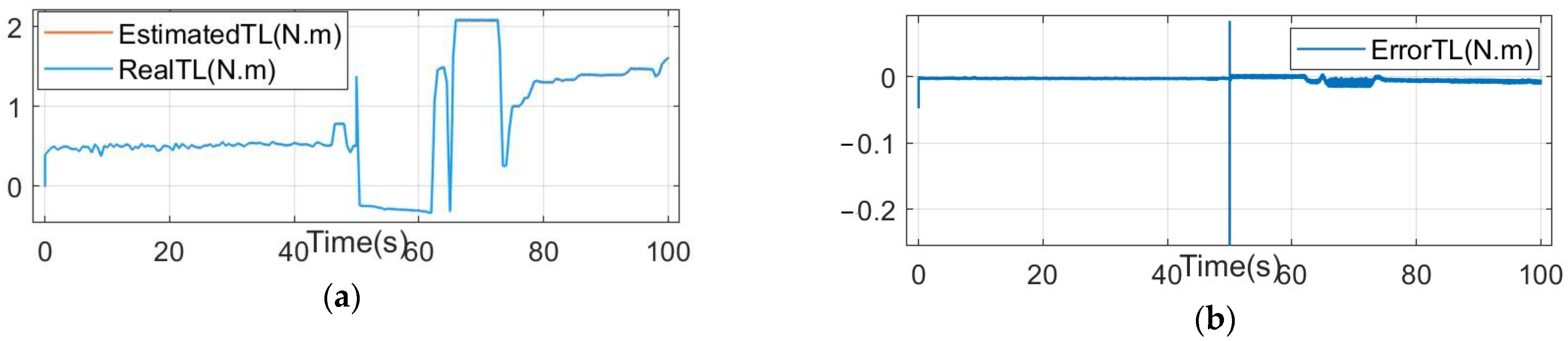
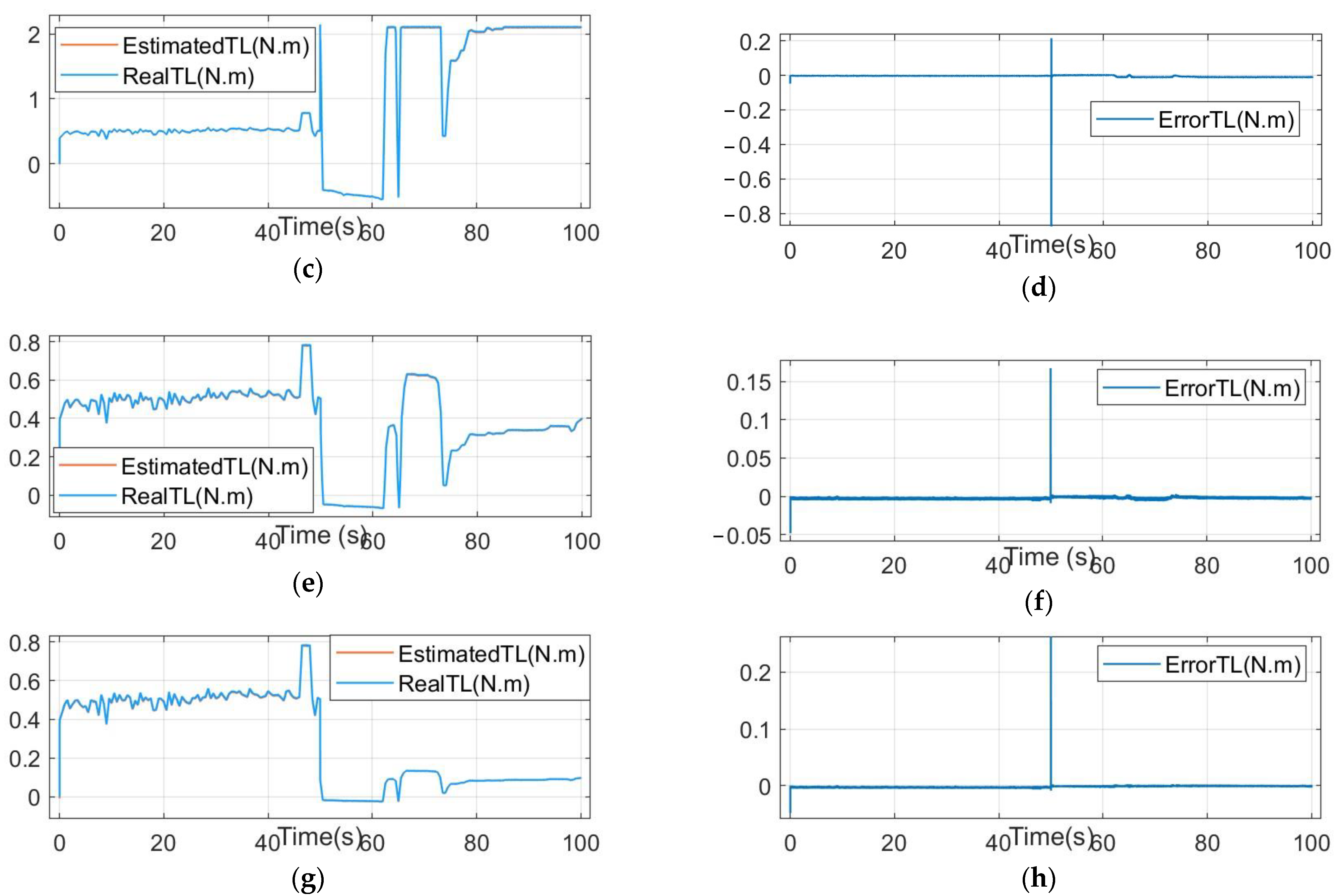
According to the above analysis, the problems of thruster fault diagnosis are mainly divided into three stages: first, the thruster load TL is estimated, according to the thruster mathematical model. Second, the thruster fault characteristic parameters, k and B, are identified according to the estimated thruster load. Third, we define the value range of the characteristic parameters corresponding to the different faults of the thruster, and classify the identified characteristic parameters, k and B, into the corresponding fault types according to this range.

3. Thruster Fault Diagnosis

The thruster fault diagnosis process proposed in this paper is shown in 
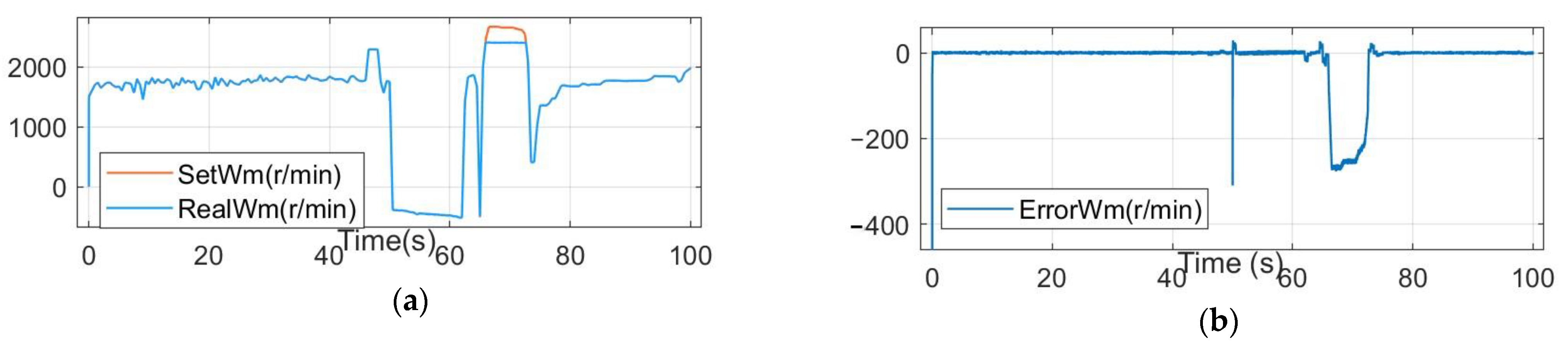
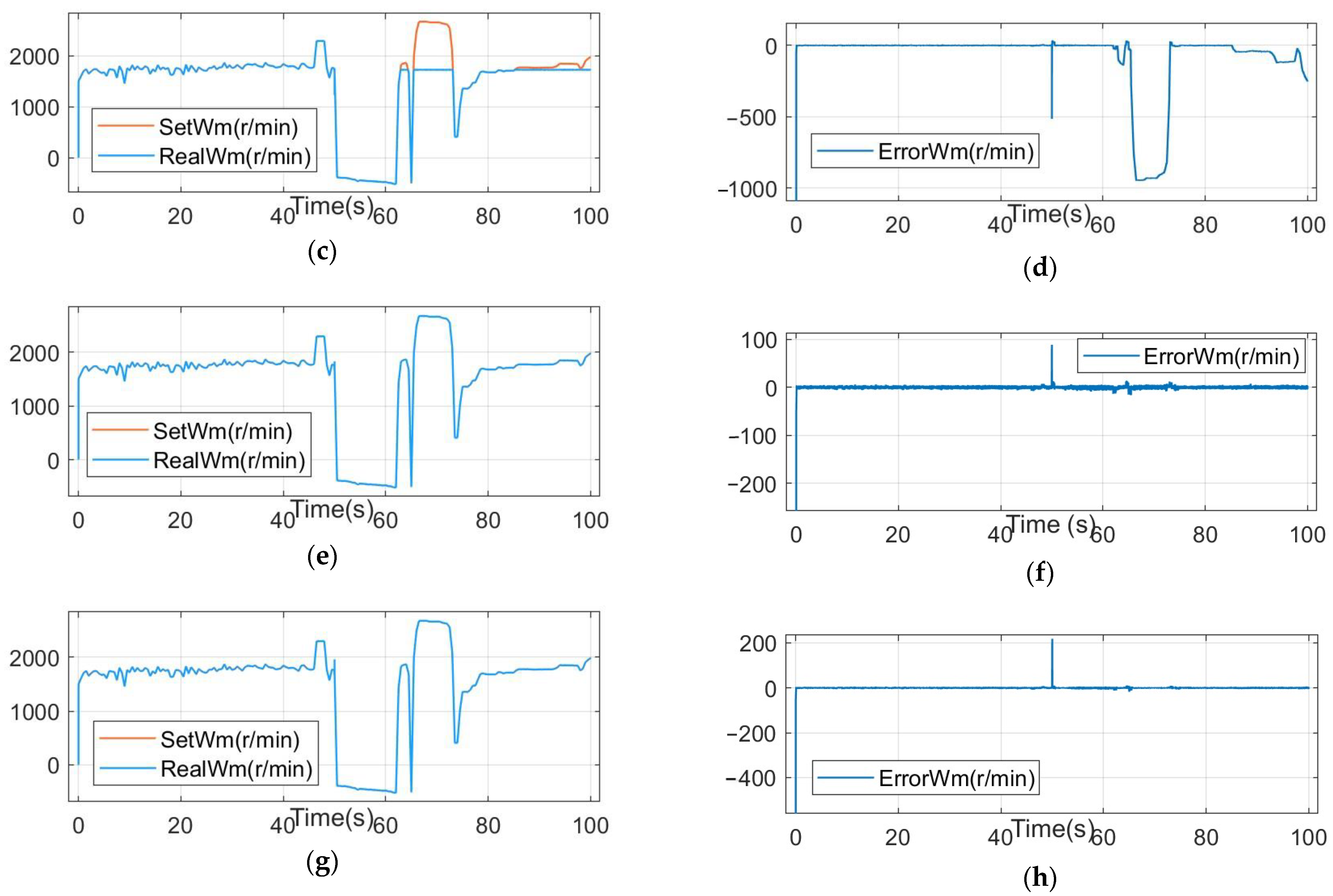
Figure 2. The double closed-loop vector control and fault simulation are necessary components for the operation of the thruster. The sliding mode observer (SMO), the least square method (LSM), and the support vector machine (SVM) are the parts of the thruster fault diagnosis. The double closed-loop vector control includes the speed loop and current loop control. The input is the target speed of the thruster, and the output is the actual speed of the thruster, ωm, and the q-axis current, iq. In the fault simulation part, according to the characteristic parameters k and B, the load torque, TL, is applied to the thruster to simulate the different fault types of the thruster. The SMO estimates the thruster load torque, T L ^ , based on the inputs ωm and iq. The LSM identifies the fault characteristic parameters k ^ and B ^ , based on the inputs ωm and T L ^ . The support vector machine realizes the classification of the thruster fault pattern, according to the trained classification model and the fault characteristic parameters, k ^ and B ^ .

3.1. Load Torque Estimation

The SMO can reduce the estimation error of all states to zero in a limited time, which can be used to solve the problem of sensor fault diagnosis and reconstruction [29]. SMO is widely used in the field of motor control. Compared with the Lomborg observer, extended Kalman filter observer, and other observers, it has the advantages of a simple structure, a small code amount, and few debugging parameters. In this paper, the SMO is used to reduce the propeller speed error to zero, according to the input and output of the propeller system, and then the load torque TL of the propeller is estimated.
According to (4) and (5),the deformation of the mechanical motion equation of the propeller is:
d ω m d t = F J ω m + 1.5 p n ψ f J i q T f J 1 J T L
where Ld = Lq for a surface-mounted rotor PMSM.
According to (10), the SMO is designed as:
d ω ^ m d t = F J ω ^ m + 1.5 p n ψ f J i q T f J 1 J T ^ L
T ^ L = h sign ( ω ^ m ω m )
where ω ^ m and T ^ L are the estimation of the mechanical angular velocity and load torque of the propeller, respectively. h is the sliding mode gain, and sign() is the sign function.
According to (10) and (11), it gives
d ω ˜ m d t = F J ω ˜ m 1 J T ˜ L T ˜ L = T ^ L T L = h · sign ( ω ^ m ω m ) T L ω ˜ m = ω ^ m ω m
where T ˜ L is the torque error and ω ˜ m is the mechanical angular velocity error of the thruster.
According to Equation (13), if ω ^ m converges to ω m , T ^ L converges to T L , and then T L = h sign ( ω ^ m ω m ) . The sliding mode gain, h, determines whether the system converges and also the rate of convergence. If the sliding mode gain is set to be too small, the system diverges. If the sliding mode gain is set to be too large, the system will converge but will produce large error fluctuations. Therefore, the selection of the sliding mode gain should be appropriate.
To calculate the value range of sliding mode gain h, let s = ω ˜ m , and we introduce the Lyapunov function:
U ( s ) = 1 2 s 2 .
To satisfy the global asymptotic stability of the system at the equilibrium point, s = 0, then:
U ( s ) 0 ( take   =   only   when   s = 0 ) U ( s ) < 0 ( s 0 )
U ( s ) 0 is obviously true. If U ( s ) < 0 is true, according to Equation (13), h should meet:
ω ˜ m ( F J ω ˜ m 1 J ( h sign ( ω ˜ m ) T L ) ) < 0 h > T L F | ω ˜ m |
To reduce the error fluctuation under the condition that the sliding mode observer converges, the load torque T ^ L of the sliding mode observer is expressed as:
T ^ L = { h sign ( ω ^ m ω m ) H , ω ^ m ω m > H h ( ω ^ m ω m ) , ω ^ m ω m H
At this point, when the error ω ˜ m between the estimated speed ω ^ m and the actual speed ω m of the propeller is greater than the threshold H (H ≥ 1), the absolute value of the sliding mode gain is h∙H, and the observer converges quickly. When the error ω ˜ m is less than or equal to the threshold, H, the absolute value of the sliding mode gain is less than h∙H. With the decrease in the error, ω ˜ m , the fluctuation of the estimated load torque, T ^ L , is smaller.

3.2. Parameter Identification

There are many methods for parameter identification. The LSM is the most widely used classical algorithm for parameter identification problems. It has the characteristics of a simple objective function, zero minimum objective function value, and moderate computation [30]. This method is applied to the identification of the thruster fault characteristic parameters, k and B.
Theoretically, k and B can be solved according to the two groups of information in TL and ωm. However, using the estimated values of the torque and speed of the thruster to solve the equations may lead to contradictions and cannot obtain the solutions in the usual sense. At this point, we find k ^ and B ^ , and make T ^ L = k ^ ω m | ω m | + B ^ ω m and TL the closest to represent the solution of the problem, which is usually represented by a 2-norm:
A x b 2 = min A y b 2 ; y C n A = [ ω m 1 | ω m 1 | ω m 1 ω m 2 | ω m 2 | ω m 2 ω m n | ω m n | ω m n ] , b = [ T ^ L 1 T ^ L 2 T ^ L n ] , x = [ k ^ B ^ ]
where x is the least-square solution of the thruster fault characteristic parameters, n is the number of rows of the least squares matrix, A, and the size of n will affect the accuracy and speed of parameter identification. C n is the set of n-dimensional complex vectors, and y is an element in the C n set.
n groups of data are intercepted through the time window, and the identification of fault characteristic parameters is realized, according to Equation (9). The identification result is:
x = pinv ( A ) · B
where pinv(A) is the pseudo-inverse of matrix A.

3.3. Fault Pattern Classification

SVM and random forest methods, as used in ensemble learning, are common pattern classification methods. With a simple structure, global optimality, and good generalization ability, the SVM is a common and effective algorithm for solving problems such as pattern classification and function estimation [31], but it performs poorly on large data sets. The accuracy of the random forest method is very high, and it can effectively run using large data sets, but the space and time required for training are large, and the real-time performance is poor. The data samples in this paper are small, and algorithms with high real-time performance are needed to achieve the real-time fault diagnosis of thrusters. Therefore, this paper selects the SVM method to train the fault characteristic parameters k and B, identified in Section 3.2 and realizes the fault mode classification.
The application of an SVM in thruster fault diagnosis can be divided into two steps: the establishment of the thruster fault classification model, and thruster fault pattern classification. The basic idea of the fault classification model is to find an optimal decision boundary. The decision boundary separates the positive and negative classes of the training set data samples, which maximizes the distance from any sample to the decision boundary. Thruster fault pattern classification is used to classify the data samples of a test set into the different fault types, according to the established classification model.
The input data X and learning objective Y of the training set samples are:
X = { X 1 , , X N } , Y = { y 1 , y N }
where the input data include N samples, and each sample X i = [ k ^ i , B ^ i ] ( i = 1 , , N ) contains a set of thruster fault characteristic parameters. The learning target sample y i { 1 , 1 } ( i = 1 , , N ) of the binary variable corresponds to the input data samples one by one, indicating thruster failure (negative class) and normal activity (positive class).
Let the normal vector of the decision boundary be w = [ w 1 , w 2 ] T and the decision boundary be expressed as:
w T X i + b = 0
where b is the intercept of the decision boundary.
In order to make classification accurate and establish a classification interval, then:
y i ( w T X i + b ) 1 ( i = 1 , , N ) .
At this time, the distance ds from the vector xs on the classification interval to the decision boundary is:
d s = | w T x s + b | w = 1 w .
Therefore, the problem of thruster fault classification is transformed into the problem of the conditional maximum:
{   max w 1 w   s . t .   y i ( w T X i + b ) 1 ( i = 1 , , N ) .
In the process of thruster fault diagnosis, the fault characteristic parameters k and B, when estimated individually, will deviate from their classification. If the classification is strictly via Equation (24), some data will be too close to the decision boundary, or even cannot be divided. To solve the above problems, the above formula is adjusted as:
{   max w { 1 w C i = 1 N ξ i }   s . t .   y i ( w T X i + b ) 1 ξ i ( ξ i 0 ; i = 1 , , N )
where ξi is the relaxation variable, and its value determines the classification basis of the i-th vector. C is the penalty coefficient, which indicates the tolerance of classification according to the relaxation variables. The larger the value, the more intolerable the classification.
The data of offline modeling come from the characteristic parameter signals of various fault patterns, as obtained from simulation tests. Equation (25) is a binary classification model of the thruster state. For the four types of thruster failure patterns discussed in this paper, SVM is used to establish several pairwise binary classification models for thruster failure pattern classification.

4. Simulation

In this paper, the feasibility of the thruster fault diagnosis method is verified in a Simulink environment. The parameters used to build the simulation environment mainly include permanent magnet synchronous motor (PMSM) parameters (Table 2), fault diagnosis parameters (Table 3), and fault characteristic parameters in the training phase of the thruster fault classification model (Table 4). This section includes the thruster control simulation, SMO load estimation simulation, LSM fault characteristic parameter identification simulation, and SVM fault pattern classification simulation.

4.1. Simulation of Thruster Control

A thruster with good control performance is the foundation of underwater vehicle motion and is also the key to thruster fault diagnosis in this paper. To verify the control performance of the thruster, this paper assigns speed control signals to the thruster at the fault classification model training stage and the fault pattern classification stage, respectively.
To simulate the real working conditions of the underwater thrusters, two groups of rotational speed signals are selected as the target speed control signals in the training phase of the thruster fault classification model. These two groups of control signals are the offset sine control signal and the thruster voltage control signal (reference signal) of the Jiaolong manned submersible, respectively, during a voyage of 0~100 s. The Jiaolong thruster voltage control signal range is −5~5 V, and the sampling time is 0.5 s. The actual simulation process maps the Jiaolong voltage signal to the rotational speed of −3750~3750 r/min, after linear interpolation. The offset sinusoidal control signal is a speed signal with a frequency of 1 rad/s, an amplitude of 20 r/min, and an offset of 2000 r/min. We apply load torque to the thruster, according to the fault characteristic parameters k and B in Table 4, to simulate the five states of the thruster. Each group of speed signals operates for 100 s, and five thruster states need to operate 10 times. A total of 4000 sets of identified fault characteristic parameters, k ^ and B ^ , are collected as the training set of the fault classification model. Figure 3 shows the simulation results of the thruster in a normal state, under two groups of control signals.
The results show that under the control of the above two groups of signals, the actual speed of the thruster can track the target speed in real time, and the thruster has a good control effect. The average error of the thruster speed under the control of the sinusoidal signal is about 5 r/min, with a small error fluctuation. Compared with the thruster controlled by the sinusoidal signal, the average error of the thruster speed controlled by the reference signal is larger, about 7 r/min. The large speed change rate of the reference signal is the reason for the larger thruster speed error. Especially at 64 s, the thruster speed changes to 4900 r/min within 0.5 s, and the thruster speed error is 31 r/min.
In the phase of thruster fault pattern classification, a 100 s voltage control signal between 1000 s and 1100 s of the Jiaolong manned submersible thruster is used as the target speed control signal. The thruster simulation runs for 100 s. The thrusters in the first 50 s are in the normal state, and the thrusters in the last 50 s are in a fault state. The fault characteristic parameter values of the thrusters in fault states are shown in Table 5.
The thruster speed simulation results are shown in Figure 4. The average error of speed in the first 50 s is 5 r/min, and the thruster control effect is good. The thruster switches to the fault state at 50 s, and the thruster speed will show a sudden change of about 0.03 s, due to the change in load torque, then it can reach the set speed immediately. In addition, the entanglement fault and the jamming fault will impose a large load on the thruster and may cause the thruster to slow down. At this point, the speed error is large.

4.2. Simulation of Torque Estimation

The load torque estimation results in the thruster fault pattern classification stage are shown in Figure 5. The load torque of the thruster can be estimated under normal and fault conditions, and the average torque error is small. When the thruster enters the fault state from the normal state, the load torque estimation error has a transient mutation. The maximum output torque of the thruster is about 2.1 N.m. The torque estimation error of the thruster is slightly larger when it operates at the maximum torque state.

4.3. Simulation of Parameter Identification

The size of the least-squares matrix A is n × 2, and the data is updated in the form of a rolling window. At the sampling time, the updated values of ωm and TL are filled into matrix A, and the old values are removed from the matrix. The n will affect the accuracy and real-time performance of parameter identification. In the simulation, the n value is 45. The identification results of the two characteristic parameters, k and B, in the online fault pattern classification stage are shown in Figure 6 and Figure 7. On the whole, the error between the identified parameters and the actual parameters is small. The error fluctuation mainly occurs at a fault occurrence time of 50 s and at the time points of 12 s and 62 s, when the data just fill matrix A. In addition, the thruster will also show large error fluctuations when the 73 s speed fluctuation is large. At this time, the difference between the identified value of the fault characteristics and the true value is large, which will reduce the accuracy of fault pattern classification.

4.4. Simulation of Fault Pattern Classification

In the fault pattern classification stage, the fault states of thrusters are divided into five types according to Table 5, and each type is represented by a label. The simulation time is 100 s. The first 50 s is the normal state, and the last 50 s are four fault states. The simulation results are shown in Figure 8. The data shows that the SVM can correctly classify the state of the thruster after it is started for 0.25 s under the normal state of the thruster. After the thruster fault, the SVM needs 1~5 s to correctly classify the thruster fault. The accuracy of propeller entanglement fault diagnosis is 98% (392/400). The accuracy of propeller jamming fault diagnosis is 99% (396/400). The accuracy of propeller breaking fault diagnosis is 95% (380/400). The accuracy of the fault diagnosis for the propeller falling off is 97% (388/400).
To verify the advantages of the thruster fault diagnosis method used in this paper, three groups of comparative experiments were designed. The first group of experiments used the traditional SVM method to classify thruster faults, according to the raw data of current iq and speed ωm of the thruster, which is represented by SVM(raw). The second group of experiments adopted the Tsfresh-SVM method mentioned by the authors of [12]. The third group of experiments uses the fault diagnosis method of load feature extraction mentioned in this paper, which is represented by SVM(k, B). Different from the first group of experiments, the second group and the third group of experiments need to process the raw current iq and speed ωm data before using the SVM to classify faults.
The training set and test set data of the three groups of comparative experiments are consistent with the above. The simulation runs for 100 s under five states of the thruster, respectively. The best results of the fault diagnosis of the three groups of experiments are shown in Figure 9. The results showed that in the first group of experiments, the SVM(raw) method had a high accuracy rate of 95.75% and 99.50% in diagnosing the jamming fault and falling off fault, respectively, but the accuracy rate of the normal state, entanglement fault, and breaking fault was low, at 83.00%, 86.75%, and 85.5%, respectively. The average fault diagnosis accuracy of the five states is 90.10%. The accuracy rate of the second group of experiments, using the Tsfresh-SVM method to diagnose the jamming fault, was 89.75%, while the accuracy rates of the other states were 94.00%, 93.50%, 97.00%, and 93.50%, respectively. The average diagnostic accuracy of the five states is 93.50%. The third group of experiments using the SVM(k, B) method had the highest diagnostic accuracy for the five thruster states, which were 99.25%, 96.75%, 99.50%, 98.25%, and 99.50%, respectively. The average fault diagnosis accuracy of the five states is 98.65%. The above experiments show that the fault diagnosis method based on load feature extraction, as proposed in this paper, has good stability and accuracy.

5. Conclusions

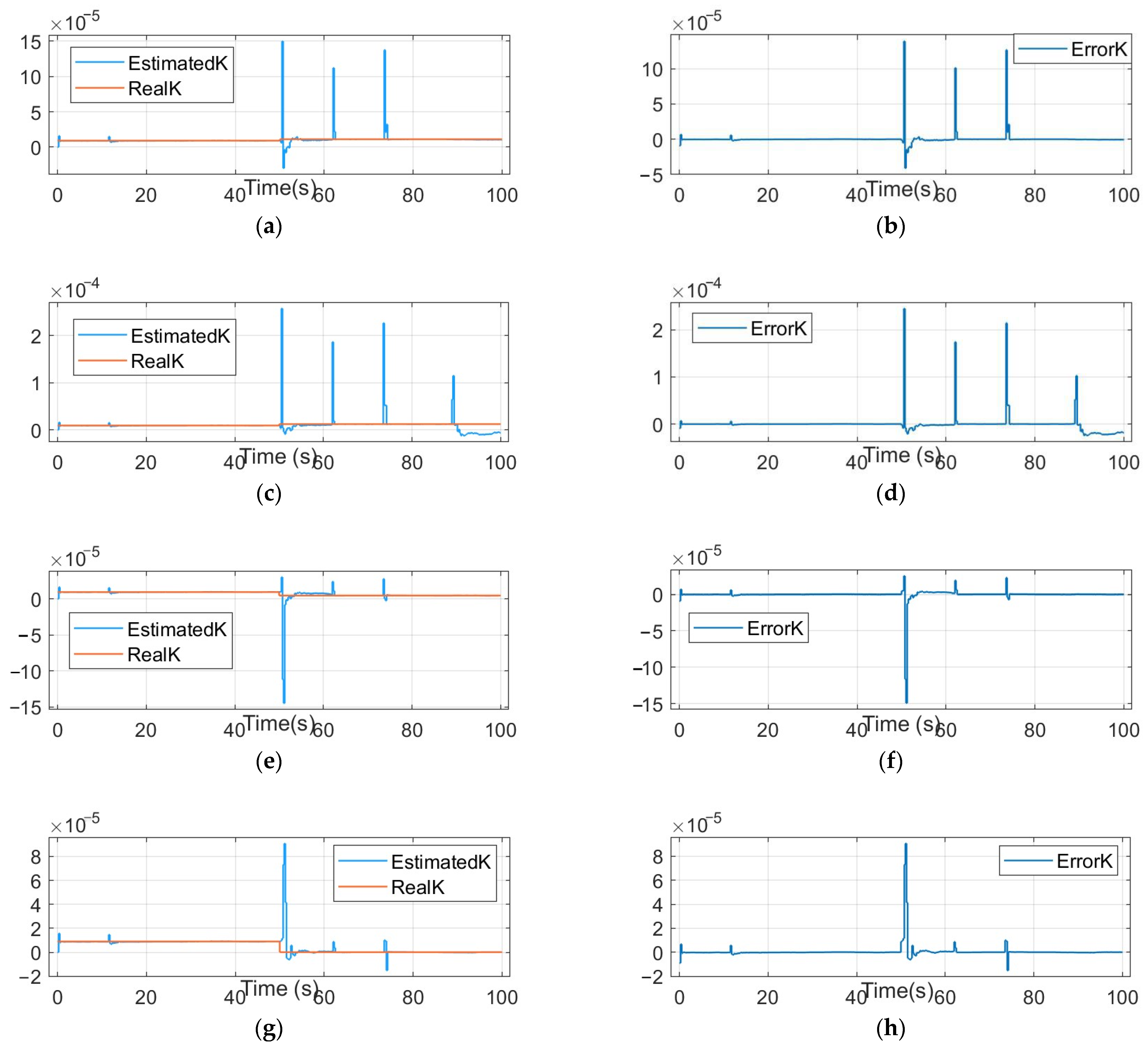
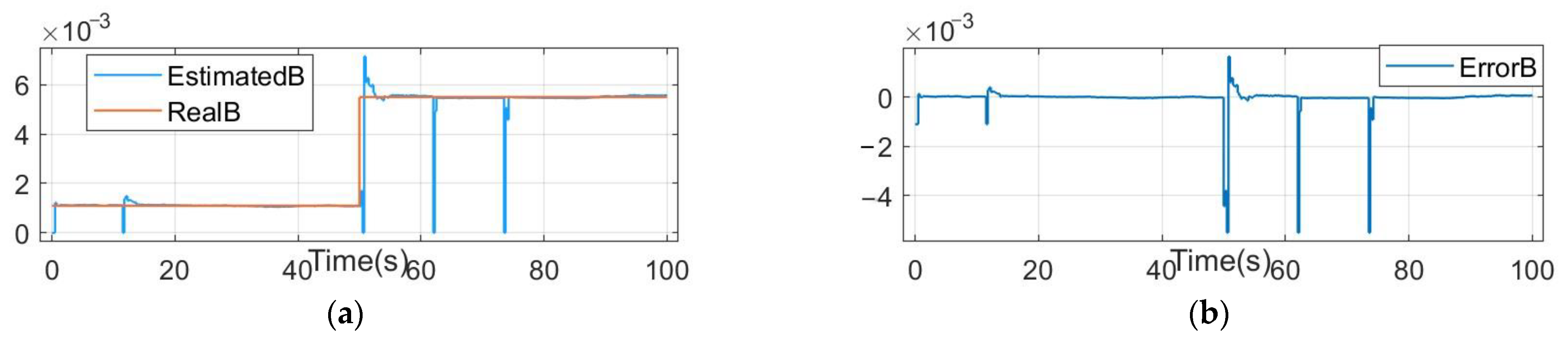
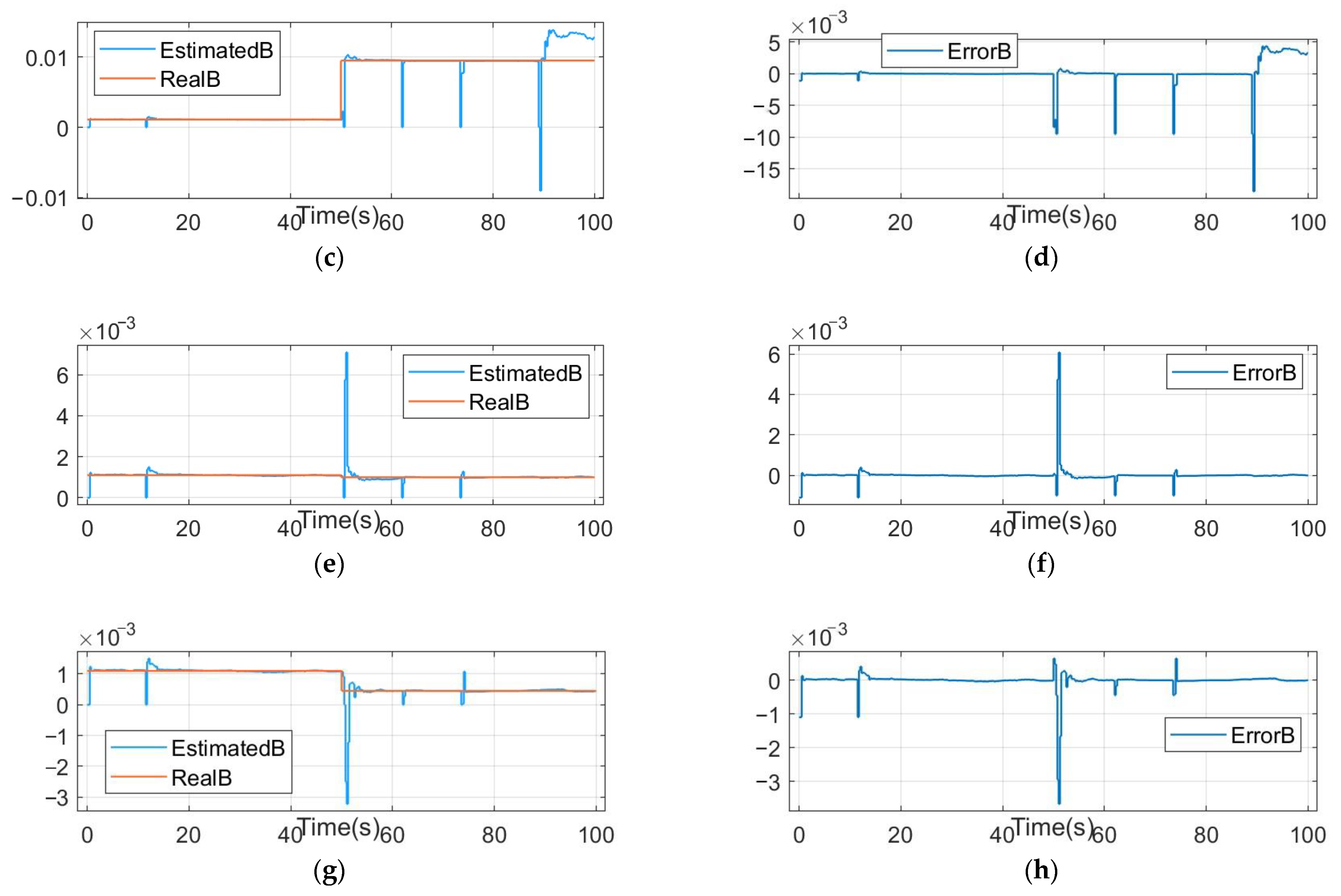
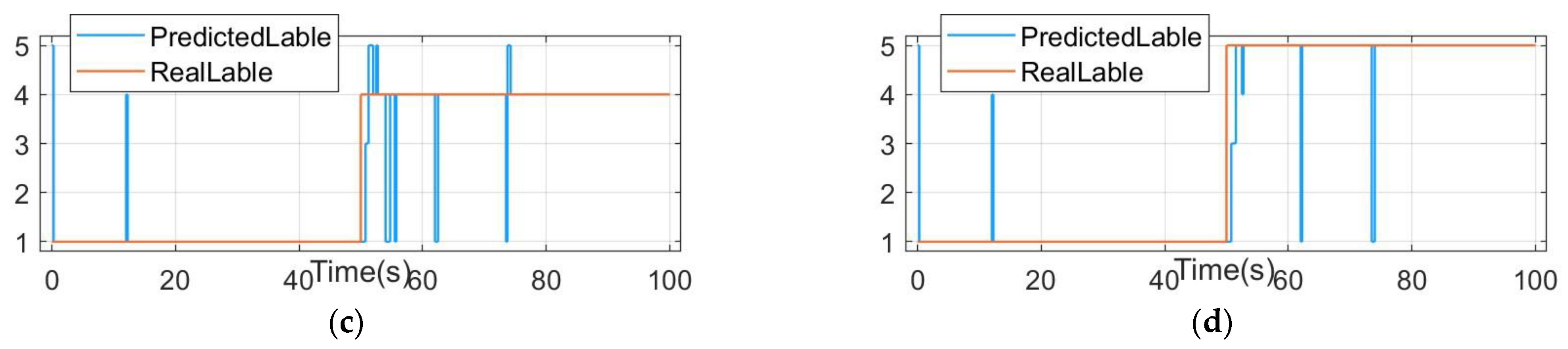
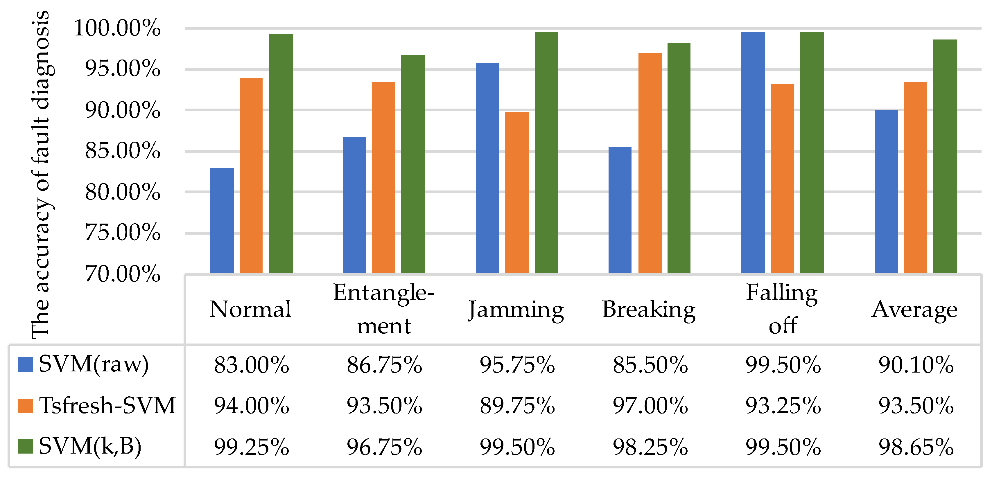
Aiming at identifying the typical faults of thrusters, this paper presents a fault diagnosis method based on thruster load feature extraction. By analyzing the load torque characteristics of propeller entanglement, jamming, breaking, falling off, and other faults, a thruster fault load torque model is established. SMO, LSM, and SVM are used to estimate the thruster load, identify the fault characteristic parameters and classify the fault patterns. The simulation results show that the proposed method is feasible in the fault pattern classification of underwater thrusters, and the accuracy of correctly identifying the fault type of thrusters within 5 s after the thruster fault occurs reaches more than 95%. In addition, three groups of contrast experiments are designed to compare the accuracy of fault diagnosis of thrusters in a single state. The results show that the fault diagnosis method based on thruster load feature extraction has the highest minimum accuracy and average accuracy for thruster fault diagnosis, which are 96.75% and 98.65% respectively.
The fault diagnosis method in this paper offers great advantages in terms of accuracy and stability, but the effectiveness of this method needs to be further verified in the real-world environment. Therefore, in future works, we plan to embed the fault diagnosis method into the underwater thruster drive system, verify the effectiveness of the fault diagnosis method on the real thruster, and realize the real-time online fault diagnosis of the thruster, taking advantage of the rapidity and accuracy of the fault diagnosis method to find faults in the propeller in good time and take measures to reduce its loss.

Author Contributions

Conceptualization, W.G. and Z.C.; data curation, Q.D.; formal analysis, W.G.; funding acquisition, Z.C.; methodology, W.G. and Z.C.; software, Q.D.; validation, Q.D.; writing—original draft, Q.D.; writing—review and editing, W.G. and Z.C. All authors have read and agreed to the published version of the manuscript.

Funding

This research was funded by the National Natural Science Foundation of China under Grant 52171313, U2006228, 51839004, 52101362, and in part by the Key Laboratory Foundation for Underwater Robot Technology under Grant 6142215200305.

Conflicts of Interest

The authors declare no conflict of interest.

Abbreviations

The following abbreviations are used in this manuscript:
SMOSliding mode observer
LSMLeast square method
SVMSupport vector machine
RFRRandom forest regression
BPNNBack propagation neural network
PMSMpermanent magnet synchronous motor

Nomenclatures

The following nomenclatures are used in this manuscript:
udStator voltage of thruster d-axis
uqStator voltage of thruster q-axis
idStator current of thruster d-axis
iqStator current of thruster q-axis
ψdStator flux linkage of thruster d-axis
ψqStator flux linkage of thruster q-axis
ωeElectrical angular velocity of thruster
RStator resistance of thruster
LdInductance of thruster d-axis
LqInductance of thruster q-axis
ψfPermanent magnet rotor flux linkage of thruster
TeElectromagnetic torque of thruster
pnNumber of magnetic pole pairs of thruster
JMoment of inertia of thruster
ωmMechanical angular velocity of thruster
TLLoad torque of thruster
TfStatic torque of thruster
FDamping coefficient of PMSM
MkPropeller torque
kmDimensionless coefficient of propeller torque
ρDensity of the water body
NnRotational speed of propeller
DpDiameter of propeller
kPropeller coefficient (fault characteristic parameter k)
MBDamping torque
BDamping coefficient of propeller (fault characteristic parameter B)
ω ^ m Estimation of mechanical angular velocity of thrusters
T ^ L Estimation of load torque of thrusters
k ^ Estimation of fault characteristic parameter k
B ^ Estimation of fault characteristic parameter B
hSliding mode gain
sign()Sign function
T ˜ L Error of load torque of thrusters
ω ˜ m Error of mechanical angular velocity of thrusters
U ( s ) Lyapunov function
HThreshold of the sliding mode gain
ALeast squares matrix
xLeast square solution of thruster fault characteristic parameters
nNumber of rows of the least squares matrix
C n Set of n-dimensional complex vectors
yAn element of C n set
pinv()pseudo inverse function
XInput data of SVM
YLearning objective of SVM
NNumber of samples of SVM input data
X i Samples of SVM input data
y i Samples of SVM learning target
w Normal vector of the decision boundary
bIntercept of decision boundary
xsVector on classification interval
dsDistance from xs to decision boundary
ξiRelaxation variable
CPenalty coefficient

References

  1. Chu, Z.Z.; Wang, F.L.; Lei, T.J.; Luo, C.M. Path planning based on deep reinforcement learning for autonomous underwater vehicles under ocean current disturbance. IEEE Trans. Intell. Veh. 2022, 1, 1. [Google Scholar] [CrossRef]
  2. Karimi, R.H.; Lu, Y.Y. Guidance and control methodologies for marine vehicles: A survey. Control Eng. Pract. 2021, 111, 104785. [Google Scholar] [CrossRef]
  3. Chen, X.; Bose, N.; Brito, M.; Khan, F.; Thanyamanta, B.; Zou, T. A review of risk analysis research for the operations of autonomous underwater vehicles. Reliab. Eng. Syst. Saf. 2021, 216, 108011. [Google Scholar] [CrossRef]
  4. Chen, Y.S.; Chu, Z.Z.; Liu, K.; Zhu, D.Q. Research progress on thruster fault diagnosis technology for deep-sea underwater vehicle. J. Propuls. Technol. 2020, 41, 2465–2474. [Google Scholar]
  5. Yao, C.Y.; Rao, L.Q.; Chen, D.N.; Hou, X.; Lv, S.J.; Yu, C.Y. T-S dynamic fault tree analysis method. J. Mech. Eng. 2019, 55, 17–32. [Google Scholar]
  6. Wang, Z.; Sun, J.C.; Wang, Y.C.; Jiang, Y.; Jia, X.P.; Wang, F. Research on chemical process signed directed graph (SDG) fault diagnosis based on complex network. Chem. Ind. Eng. Prog. 2016, 35, 1344–1352. [Google Scholar]
  7. Li, J.; Zhang, K.Y.; Li, H.B.; Yang, L.J.; Wang, M.D. Analysis on the mission reliability for AUV based on Monte Carlo method. J. Syst. Simul. 2019, 31, 2131–2137. [Google Scholar]
  8. Zhang, M.J.; Wang, Y.J.; Xu, J.A.; Liu, Z.C. Thruster fault diagnosis in autonomous underwater vehicle based on grey qualitative simulation. Ocean Eng. 2015, 105, 247–255. [Google Scholar] [CrossRef]
  9. Xiang, X.B.; Yu, C.Y.; Zhang, Q. On intelligent risk analysis and critical decision of underwater robotic vehicle. Ocean Eng. 2017, 140, 453–465. [Google Scholar] [CrossRef]
  10. Esmaeili, H.; Hakami, V.; Bidgoli, M.B.; Shokouhifar, M. Application-specific clustering in wireless sensor networks using combined fuzzy firefly algorithm and random forest. Expert Syst. Appl. 2022, 210, 118365. [Google Scholar] [CrossRef]
  11. Darehnaei, Z.G.; Shokouhifar, M.; Yazdanjouei, H.; Fatemi, S.M.J.R. SI-EDTL: Swarm intelligence ensemble deep transfer learning for multiple vehicle detection in UAV images. Concurr. Comput. Pract. Exp. 2021, 34, e6726. [Google Scholar]
  12. Chu, Z.Z.; Li, Z.Q.; Gu, Z.H.; Chen, Y.S.; Zhang, M.J. A fault diagnosis method for underwater thruster based on RFR-SVM. Proc. Inst. Mech. Eng. Part M J. Eng. Marit. Environ. 2022. [Google Scholar] [CrossRef]
  13. Cheng, X.L.; Zhu, D.Q.; Sun, B.; Chen, Y.S. Principal component analysis algorithm for fault diagnosis of thruster system in deep-sea human occupied vehicle. Control Theory Appl. 2018, 35, 1796–1804. [Google Scholar]
  14. Costa, F. Fault-induced transient detection based on real-time analysis of the wavelet coefficient energy. In Proceedings of the 2014 IEEE PES T&D Conference and Exposition, Chicago, IL, USA, 14–17 April 2014. [Google Scholar]
  15. Zhang, M.J.; Yin, B.J.; Liu, W.X. Feature extraction and fusion for thruster faults of AUV with random disturbance. J. Huazhong Univ. Sci. Technol. (Nat. Sci. Ed.) 2015, 6, 22–26. [Google Scholar]
  16. Ning, J.P. Research on Fault Tolerant Control Methods for Dynamic Positioning of Ships. Ph.D. Thesis, Harbin Engineering University, Harbin, China, 2013. [Google Scholar]
  17. Xu, G.P.; Li, S.; Zeng, J.B.; Li, Y.P. Thruster fault signal diagnosis of underwater vehicle. Comput. Simul. 2019, 36, 296–301, 327. [Google Scholar]
  18. Gu, L.Z.; Xie, Z.X. A Review of the research on the fault diagnosis of underwater vehicle propeller. Sci. Technol. Inf. 2016, 14, 110290. [Google Scholar]
  19. Chu, Z.Z.; Meng, F.; Zhu, D.Q.; Luo, C.M. Fault reconstruction using a terminal sliding mode observer for a class of second-order MIMO uncertain nonlinear systems. ISA Trans. 2020, 97, 67–75. [Google Scholar] [CrossRef]
  20. Zhao, B.; Skjetne, R.; Blanke, M.; Dukanet, F. Particle filter for fault diagnosis and robust navigation of underwater robot. IEEE Trans. Control Syst. Technol. 2014, 22, 2399–2407. [Google Scholar] [CrossRef] [Green Version]
  21. Liu, F.Q.; Xu, D.M.; Gao, J.; Zhang, L.C. Fault diagnosis and fault tolerant control for actuators of underwater vehicles. Control Theory Appl. 2014, 31, 1143–1150. [Google Scholar]
  22. Liu, W.; Ren, S.Z.; Zhang, Z.Q. A Magnetic Coupling Underwater Propeller. CN207496908U, 15 June 2018. [Google Scholar]
  23. Yuan, L.; Hu, B.X.; Wei, K.Y.; Chen, S. Modern Permanent Magnet Synchronous Motor Control Principle and Matlab Simulation; Beihang University Press: Beijing, China, 2016. [Google Scholar]
  24. Ruan, Y.; Yang, Y. Control Systems of Electric Drives; China Machine Press: Beijing, China, 2016. [Google Scholar]
  25. Li, Z.; Hu, G.D.; Cui, J.R.; Liu, G.Y. Sliding-mode variable structure control with integral action for permanent magnet synchronous motor. Proc. CSEE 2014, 34, 431–437. [Google Scholar]
  26. Luo, Y.; Li, Z.D.; Tao, J.G.; Deng, L.P.; Deng, Z.Q. Thrust prediction of underwater blade-propeller-type thrusters under quasi-cavitation. J. Mech. Eng. 2020, 56, 1–11. [Google Scholar]
  27. Ren, J.J.; Liu, Y.C.; Zhao, Y.T.; Guo, H.H. Research on the direct torque control system of PMSM with propeller load. Electr. Mach. Control 2012, 16, 45–51. [Google Scholar]
  28. Yan, Q.Q.; Yang, J.Z. The damping mechanism of a kind of micro-isolator. Spacecr. Environ. Eng. 2013, 30, 392–396. [Google Scholar]
  29. Chu, Z.Z.; Zhang, M.J. Fault reconstruction of thruster for autonomous underwater vehicle based on terminal sliding mode observer. Ocean Eng. 2014, 88, 426–434. [Google Scholar] [CrossRef]
  30. Li, H.M.; Chen, T. Review of research on parameter identification of PMSM. J. Electron. Meas. Instrum. 2015, 29, 638–647. [Google Scholar]
  31. Wang, H.Y.; Li, J.H.; Yang, F.L. Overview of support vector machine analysis and algorithm. Appl. Res. Comput. 2014, 3, 1281–1286. [Google Scholar]
Figure 1. Magnetically coupled underwater thruster.
Electronics 11 03714 g001
Figure 2. Thruster fault diagnosis block diagram.
Electronics 11 03714 g002
Figure 3. Speed control of the thruster in a normal state: (a) thruster speed control, with the reference signal; (b) control error of the thruster, using the reference signal; (c) thruster speed control, with the sinusoidal signal; (d) control error of the thruster, using a sinusoidal signal.
Electronics 11 03714 g003aElectronics 11 03714 g003b
Figure 4. Speed control of the thruster in the fault states: (a) thruster speed control with an entanglement fault; (b) control error of a thruster with an entanglement fault; (c) thruster speed control with a jamming fault; (d) control error of a thruster with a jamming fault; (e) thruster speed control with a breaking fault; (f) control error of a thruster with a breaking fault; (g) thruster speed control with a falling-off fault; (h) control error of a thruster with a falling-off fault.
Electronics 11 03714 g004aElectronics 11 03714 g004b
Figure 5. Load torque estimation of the thruster in the fault states: (a) torque estimation of a thruster with an entanglement fault; (b) torque estimation error of a thruster with an entanglement fault; (c) torque estimation of a thruster with a jamming fault; (d) torque estimation error of a thruster with a jamming fault; (e) torque estimation of a thruster with a breaking fault; (f) torque estimation error of a thruster with a breaking fault; (g) torque estimation of a thruster with a falling-off fault; (h) torque estimation error of a thruster with a falling-off fault.
Electronics 11 03714 g005aElectronics 11 03714 g005b
Figure 6. Parameter k identification of the thruster in the fault states: (a) parameter k identification of a thruster with an entanglement fault; (b) parameter k error of a thruster with an entanglement fault; (c) parameter k identification of a thruster with a jamming fault; (d) parameter k error of a thruster with a jamming fault; (e) parameter k identification of a thruster with a breaking fault; (f) parameter k error of a thruster with a breaking fault; (g) parameter k identification of a thruster with a falling off fault; (h) parameter k error of a thruster with a falling-off fault.
Electronics 11 03714 g006
Figure 7. Parameter B identification of the thruster in fault states: (a) parameter B identification of a thruster with an entanglement fault; (b) parameter B error of a thruster with an entanglement fault; (c) parameter B identification of a thruster with a jamming fault; (d) parameter B error of thruster with jamming fault; (e) parameter B identification of a thruster with a breaking fault; (f) Parameter B error of thruster with breaking fault; (g) Parameter B identification of thruster with falling off fault; (h) Parameter B error of thruster with falling off fault.
Electronics 11 03714 g007aElectronics 11 03714 g007b
Figure 8. Fault mode classification of thruster in fault states: (a) fault mode classification of a thruster with an entanglement fault; (b) fault mode classification of a thruster with a jamming fault; (c) the fault mode classification of a thruster with a breaking fault; (d) fault mode classification of a thruster with a falling-off fault.
Electronics 11 03714 g008aElectronics 11 03714 g008b
Figure 9. Comparative experiments of the thruster fault diagnosis methods.
Electronics 11 03714 g009
Table 1. Relationship between the fault characteristic parameters and the faults of thrusters.
Fault TypeTLkB
Entanglementincreaseunchangedincrease
Jammingsharp increaseunchangedsharp increase
Breakingdecreasedecreaseunchanged
Falling offsharp decreasesharp decreasedecrease
Table 2. Parameters of the thruster permanent magnet synchronous motor (PMSM).
ParameterValue
Rated voltage (V)150
Phase resistance (Ohm)1.6
Armature inductance (H)2 × 10⁻³
Torque constant (N.m/A)0.2
Moment of inertia (kg.m2)2.3 × 10⁻⁵
Viscous damping (N.m.s)3.3 × 10⁻⁵
Pole pairs10
Static friction (N.m)6 × 10⁻⁴
Table 3. The parameters for fault diagnosis.
ParameterValue
Sampling time of speed PI controller (s)1 × 10⁻³
Sampling time of current PI controller (s)1 × 10⁻⁵
Sampling time of SMO (s)1 × 10⁻⁵
H (Threshold of sliding mode gain)1
h (Sliding mode gain)4
n (Size of the least squares matrix)45
Sampling time of LSM (s)0.25
Sampling time of SVM (s)0.25
Sampling time of simulation system (s)5 × 10⁻⁶
Table 4. Fault characteristics parameters of the thrusters (training set).
Fault typekBLabel
Normal1 × 10−51 × 10−31
Entanglement1 × 10−55 × 10−32
Jamming1 × 10−51 × 10−23
Breaking5 × 10−61 × 10−34
Falling off05 × 10−45
Table 5. Fault characteristics parameters of the thrusters (test set).
Fault TypekBLabel
Normal9 × 10−61.1 × 10⁻³¹
Entanglement1.1 × 10−55.5 × 10⁻³²
Jamming1.2 × 10−59.5 × 10⁻³³
Breaking4.5 × 10−61 × 10−34
Falling off1 × 10−74.5 × 10−45
Publisher’s Note: MDPI stays neutral with regard to jurisdictional claims in published maps and institutional affiliations.

