
Intelligent Fault Detection in Hall-Effect Rotary Encoders for Industry 4.0 Applications
 ,
,  , ,
, ,  , and
, and 
Abstract
:1. Introduction
2. Mathematical Modeling
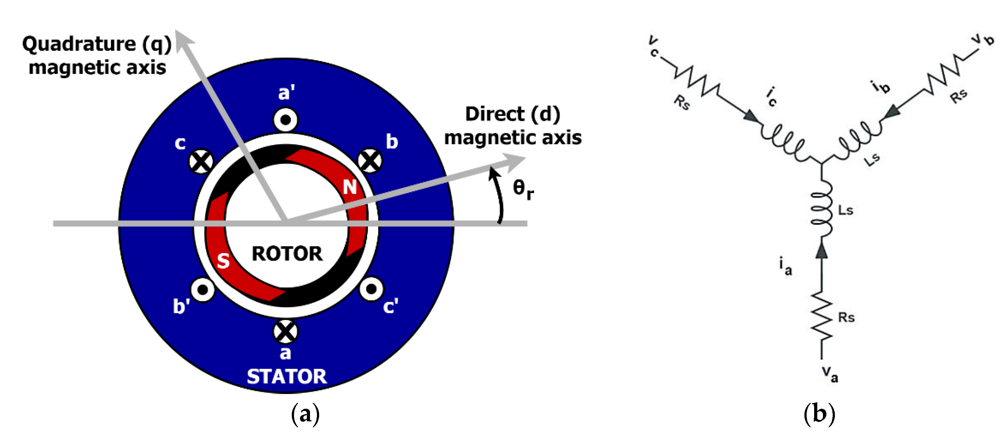
2.1. PMSM Modeling
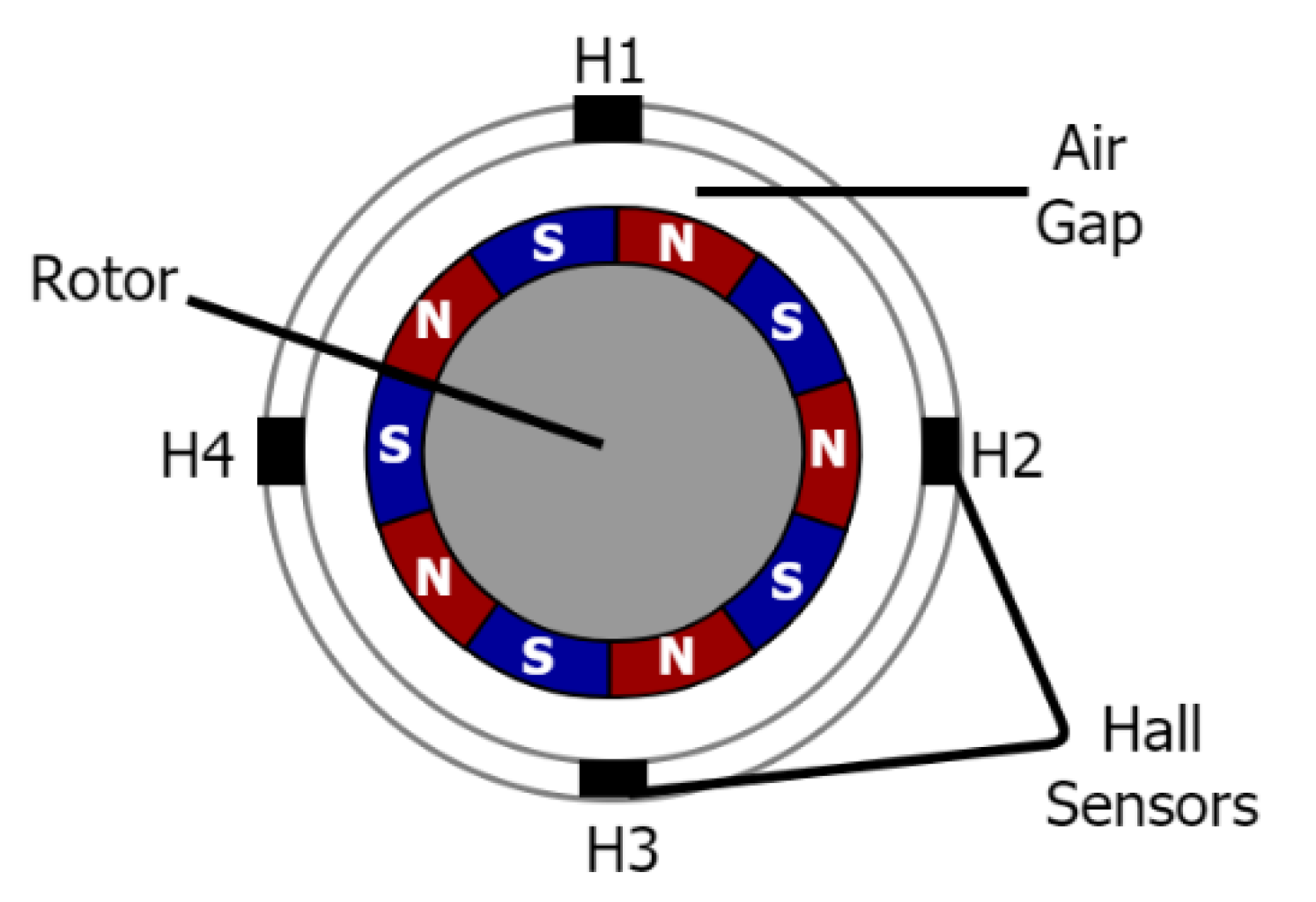
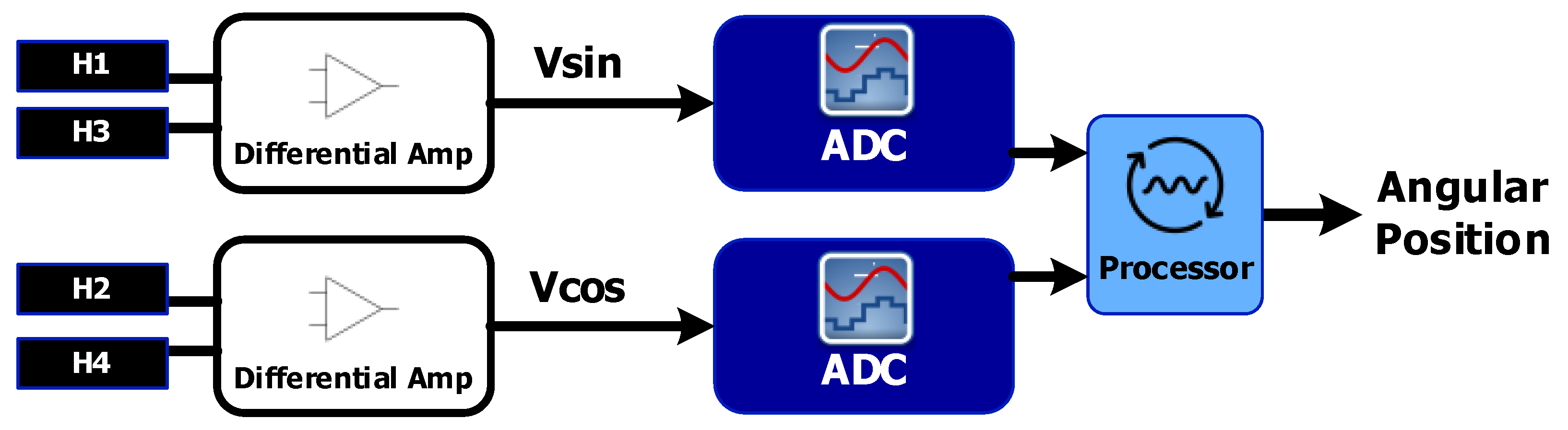
2.2. Four-Element Hall-Effect Rotary Encoder
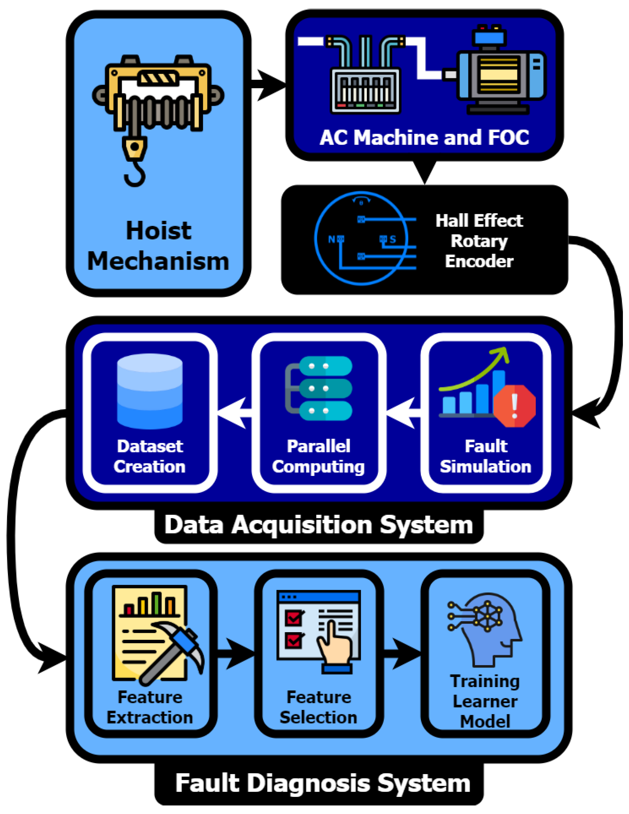
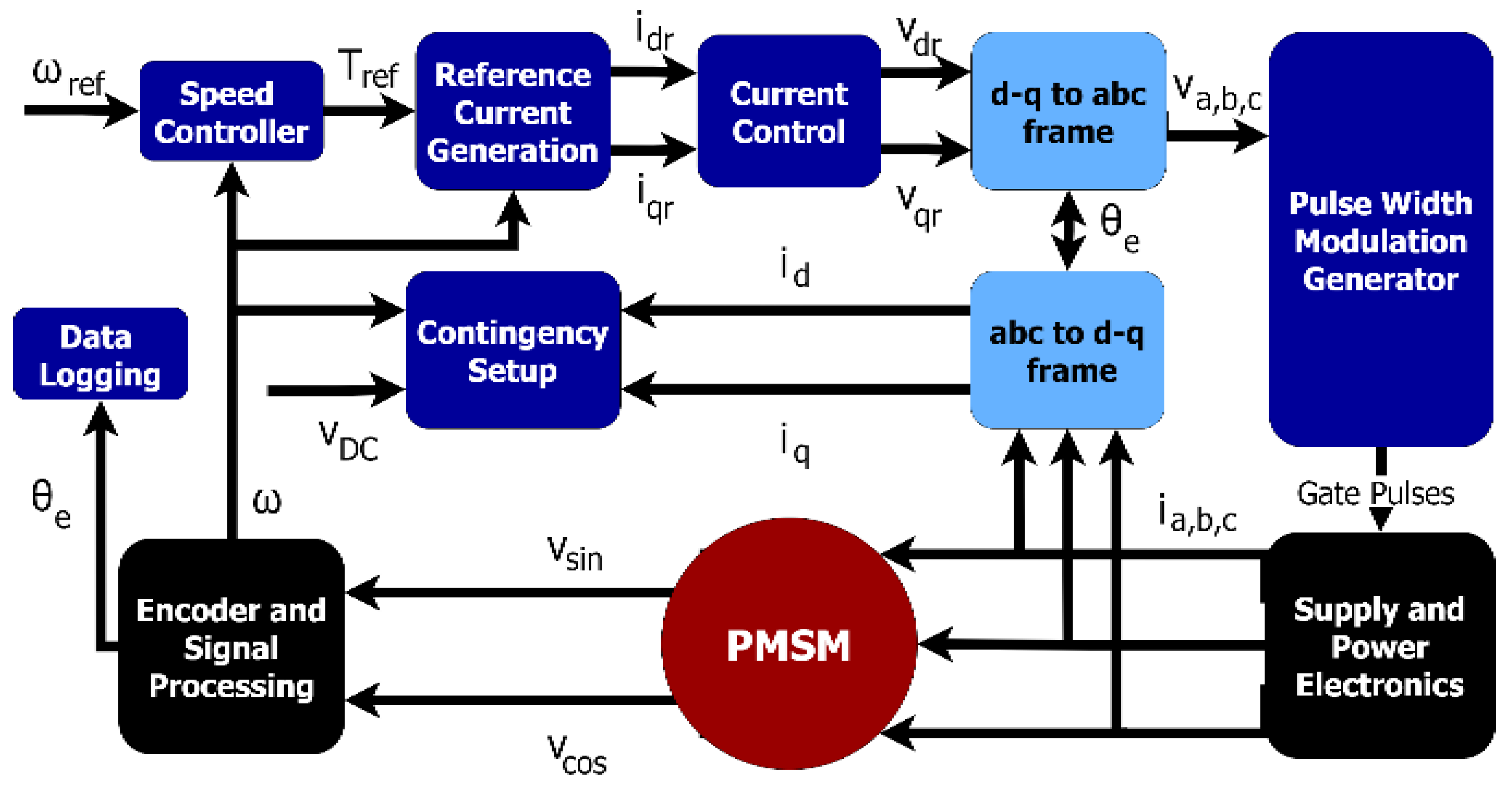
3. Design of FOC-Based PMSM Drive with Fault Creation and Data Extraction
3.1. Motor and FOC Architecture
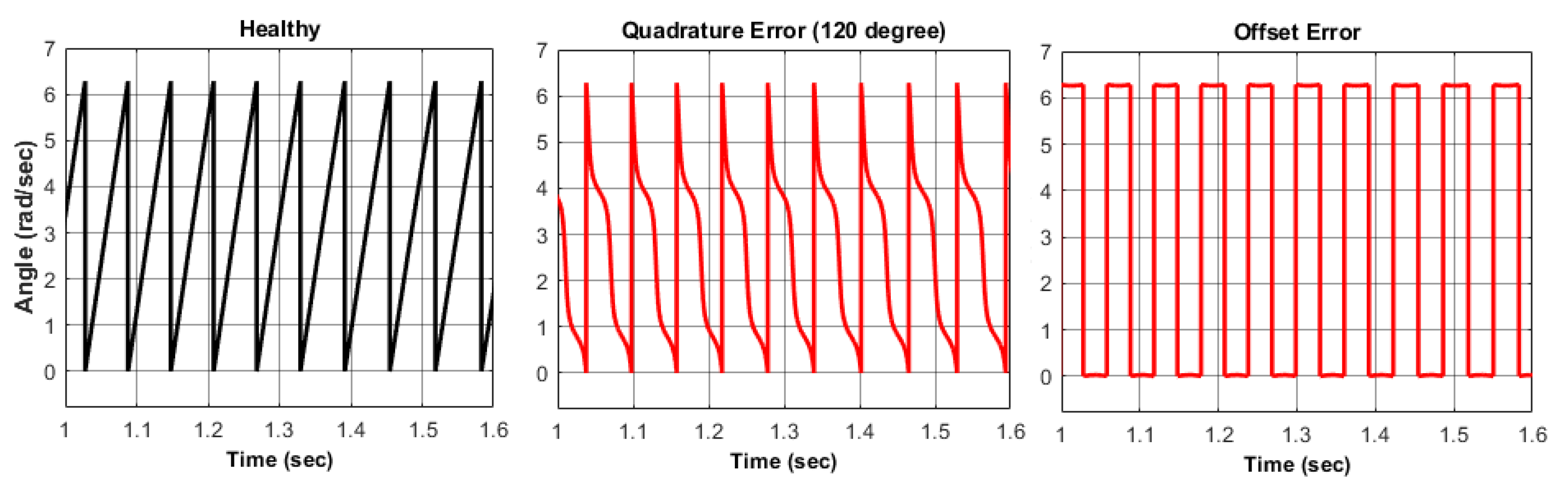
3.2. Hall-Effect Rotary Encoder Operation and Faults
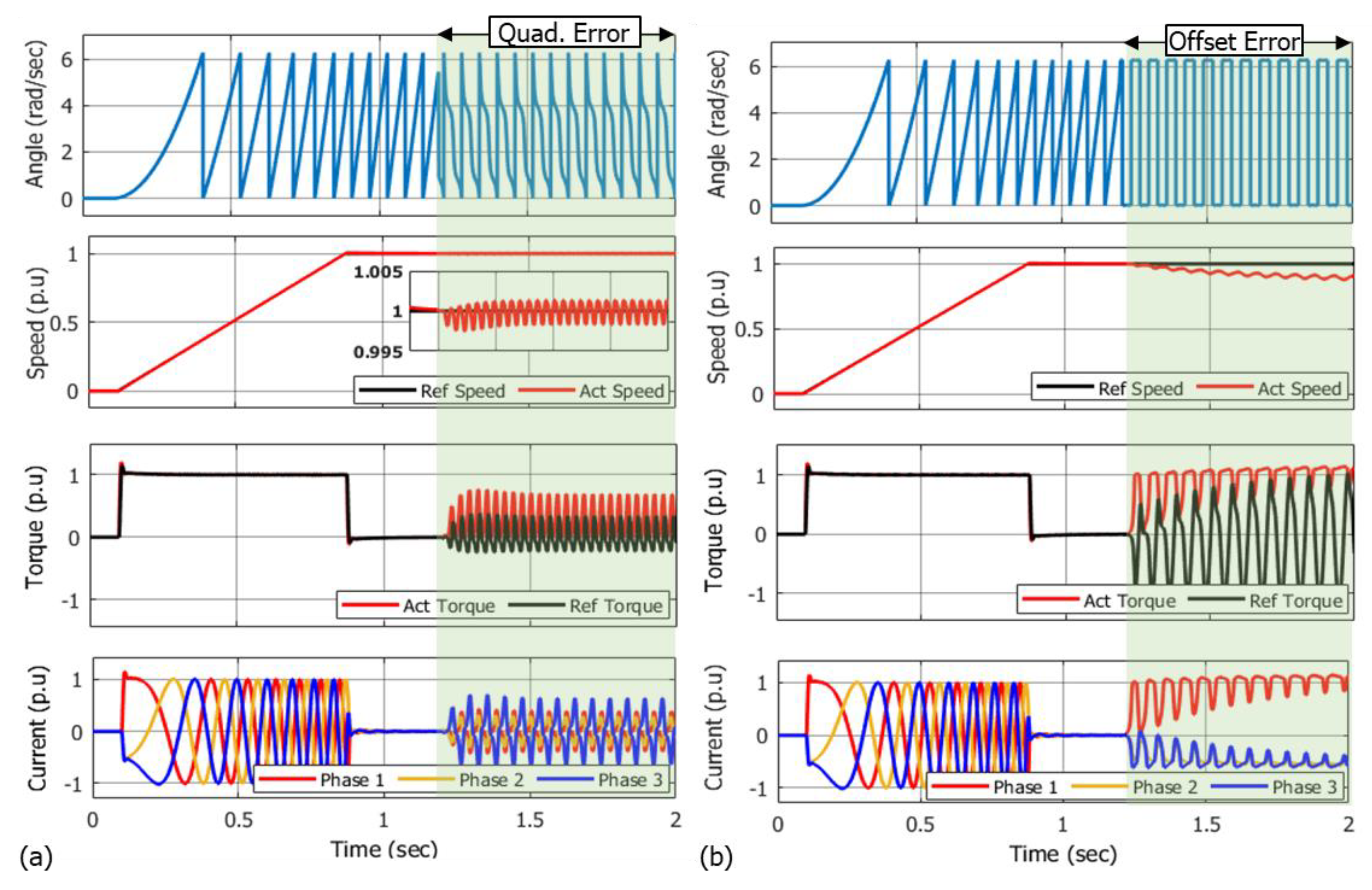
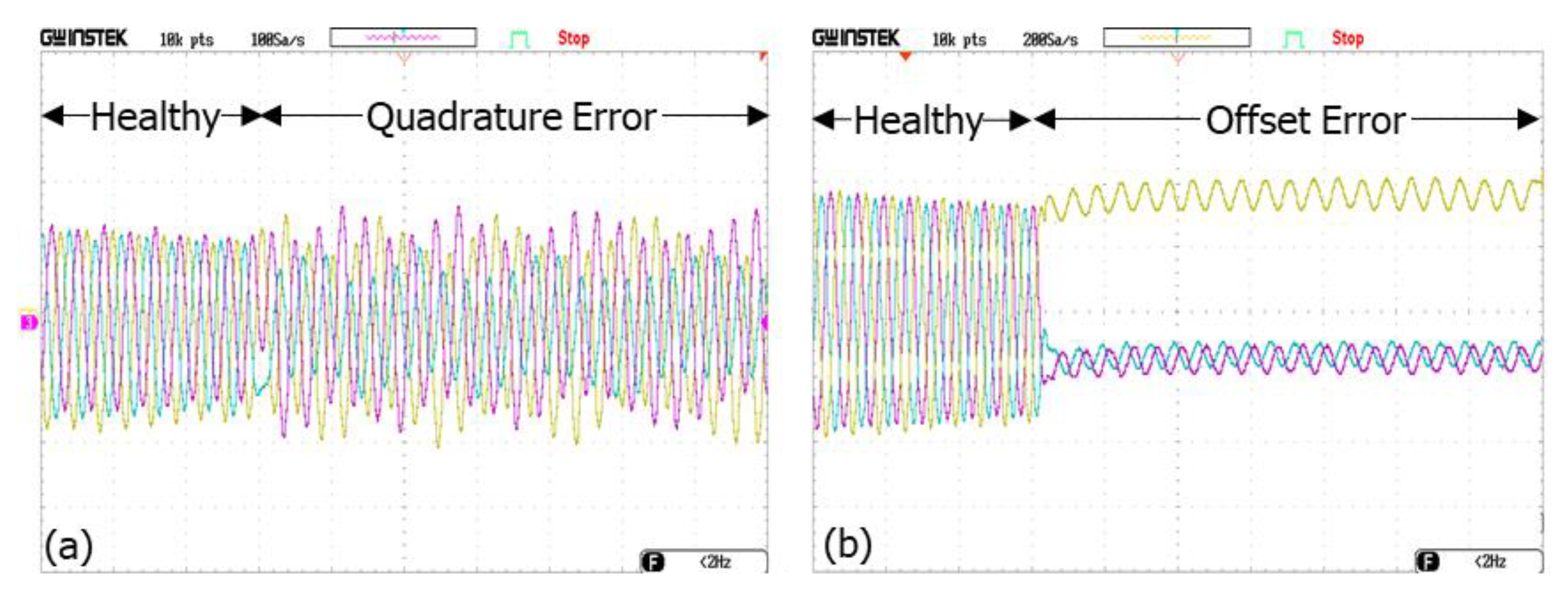
- Quadrature error (QE): Quadrature detection in rotary encoders allows the user to monitor the speed and direction of rotation, and incremental changes in angle [28]. Placement and alignment errors, magnet tilt, and off-axis magnet rotation may all contribute to a total measurement error known as quadrature error. Additionally, variations in device sensitivity will impact overall quadrature accuracy. During continuous rotation, small quadrature errors for speed calculations may average out over time, but detecting distinct pole transitions for the absolute position requires finer precision.
- Offset error (OE): Offset errors occur primarily in the Hall element and are due to poor transistor matching of the components in the analogue signal path [26]. An offset voltage may also develop due to non-ideal temperature conditions [29]. In well-designed sensor elements, these errors are small and existing OEs can be tackled with offset compensation and front-end calibration.
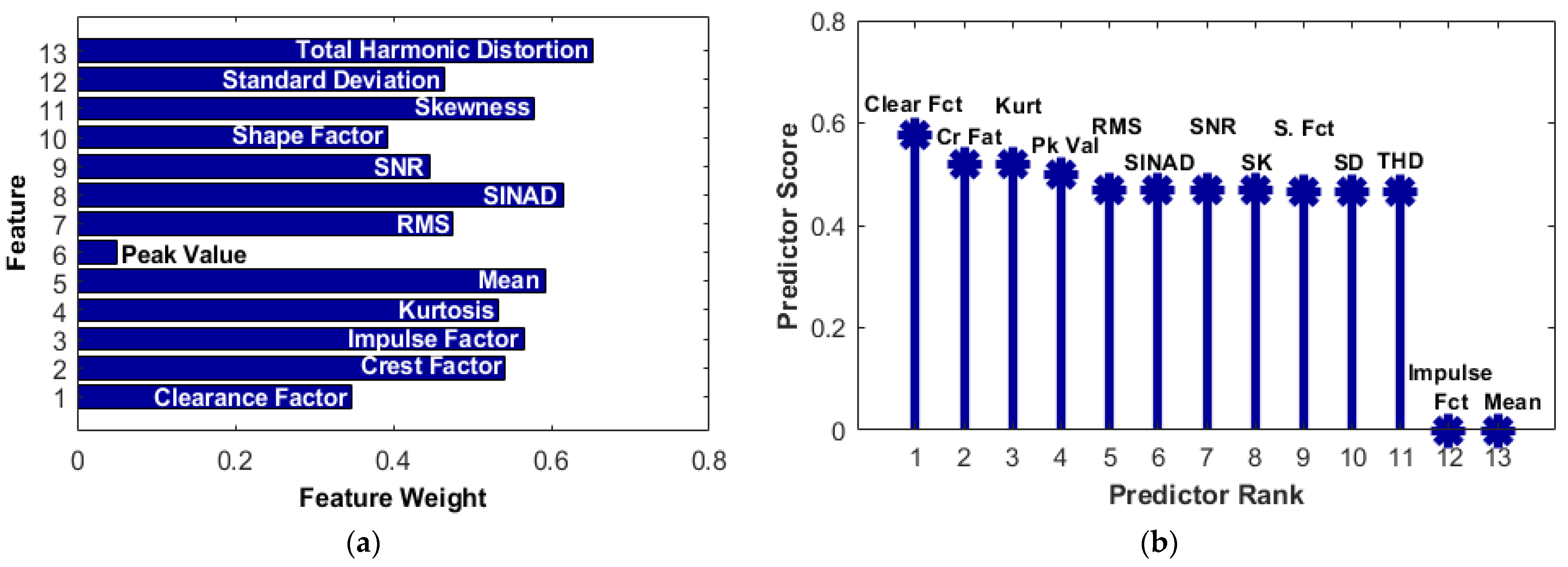
3.3. Data Extraction and Classification
4. Realization of FOC for PMSM Drive System for Sensor Fault Detection
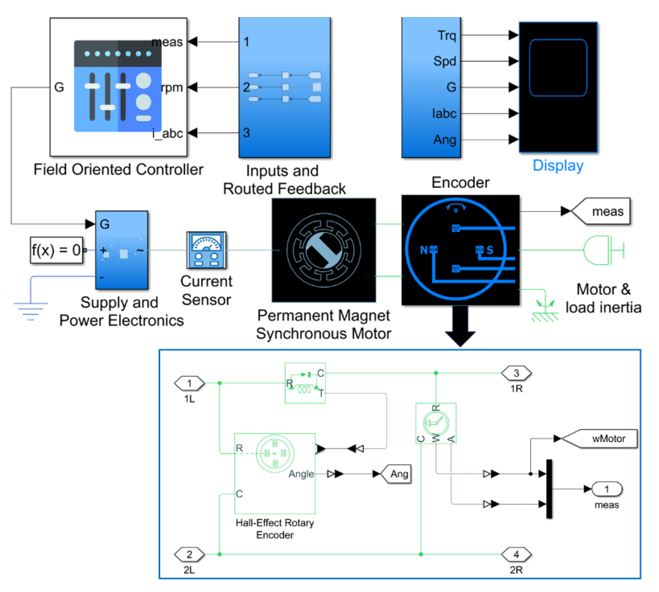
4.1. Simscape Model of PMSM Drive System
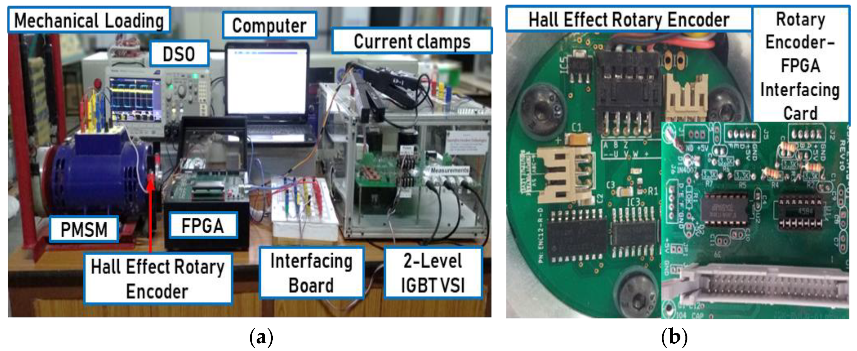
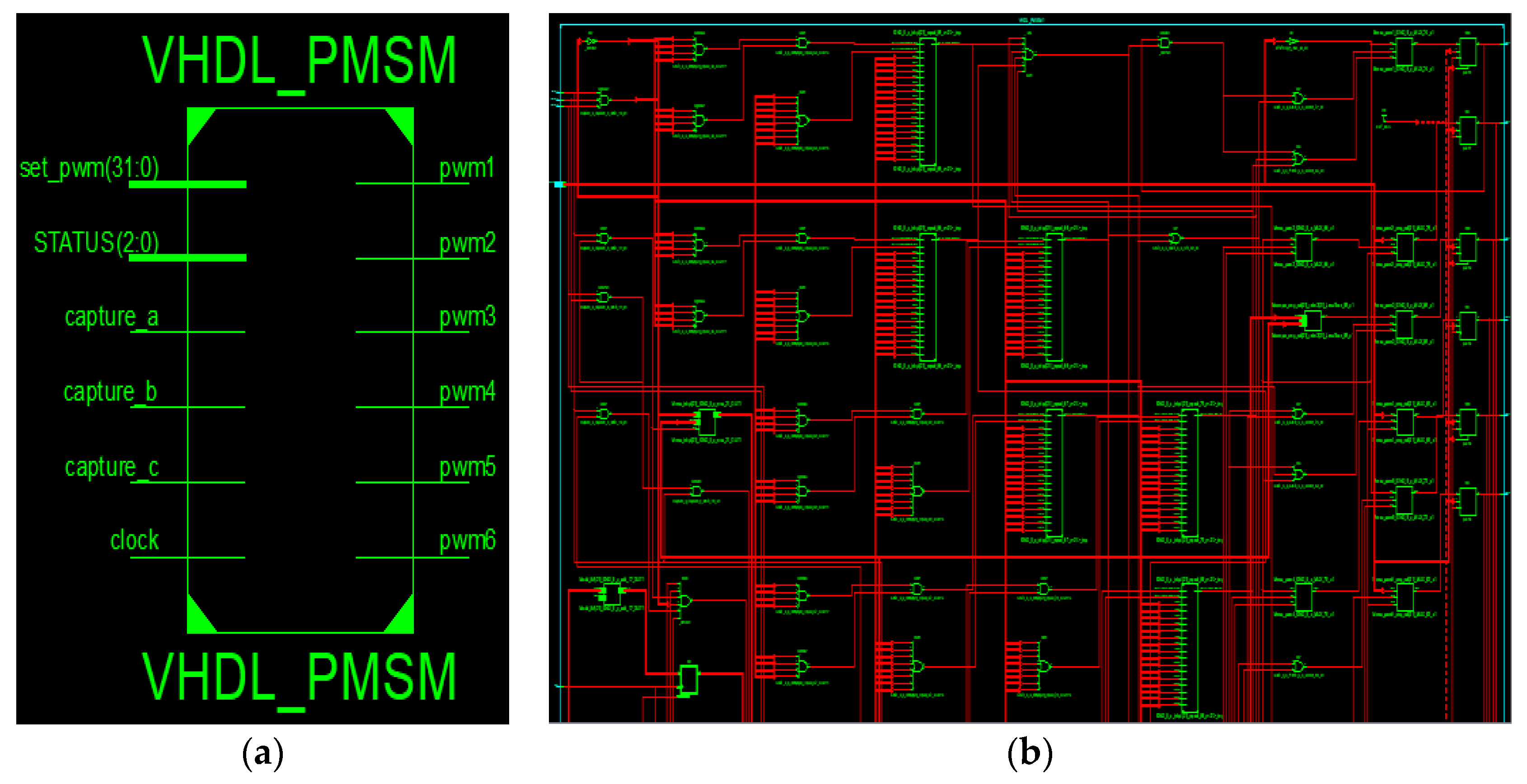
4.2. Prototype Hardware of PMSM Drive System
5. Results and Discussion
6. Conclusions
Author Contributions
Funding
Data Availability Statement
Conflicts of Interest
References
- Tao, F.; Anwer, N.; Liu, A.; Wang, L.; Nee, A.Y.C.; Li, L.; Zhang, M. Digital Twin towards Smart Manufacturing and Industry 4.0. J. Manuf. Syst. 2021, 58, 1–2. [Google Scholar] [CrossRef]
- Morgan, J.; Halton, M.; Qiao, Y.; Breslin, J.G. Industry 4.0 Smart Reconfigurable Manufacturing Machines. J. Manuf. Syst. 2021, 59, 481–506. [Google Scholar] [CrossRef]
- Machine Design. Basics of Rotary Encoders: Overview and New Technologies. Available online: https://www.machinedesign.com/automation-iiot/sensors/article/21831757/basics-of-rotary-encoders-overview-and-new-technologies (accessed on 2 November 2022).
- Ebbesson, C. Magnetic Rotary Position Sensors. Sens. Rev. 2011, 31, 1–16. [Google Scholar] [CrossRef]
- Bharathidasan, M.; Indragandhi, V.; Suresh, V.; Jasiński, M.; Leonowicz, Z. A Review on Electric Vehicle: Technologies, Energy Trading, and Cyber Security. Energy Rep. 2022, 8, 9662–9685. [Google Scholar] [CrossRef]
- Mathis, H.A. Technical Article. Shock Vib. Dig. 1993, 25, 10–14. [Google Scholar] [CrossRef]
- Mohankumar, P.; Ajayan, J.; Yasodharan, R.; Devendran, P.; Sambasivam, R. A Review of Micromachined Sensors for Automotive Applications. Measurement 2019, 140, 305–322. [Google Scholar] [CrossRef]
- Pu, H.; Wang, H.; Liu, X.; Yu, Z.; Peng, K. A High-Precision Absolute Angular Position Sensor with Vernier Capacitive Arrays Based on Time Grating. IEEE Sens. J. 2019, 19, 8626–8634. [Google Scholar] [CrossRef]
- Bienczyk, K. Angle Measurement Using a Miniature Hall Effect Position Sensor. In Proceedings of the 2009 2nd International Students Conference on Electrodynamic and Mechatronics, Opole, Poland, 19–21 May 2009; pp. 21–22. [Google Scholar]
- Beigel, J. Using Hall Effect Sensors for Rotary Encoding Applications Hall Effect Sensors, Texas Instruments, Technical White Paper. 2022. Available online: https://www.ti.com/lit/pdf/slya063 (accessed on 2 November 2022).
- Hu, J.; Zou, J.; Xu, F.; Li, Y.; Fu, Y. An Improved PMSM Rotor Position Sensor Based on Linear Hall Sensors. IEEE Trans. Magn. 2012, 48, 3591–3594. [Google Scholar] [CrossRef]
- Song, X.; Jiancheng, F.; Bangcheng, H. High-Precise Rotor Position Detection for High-Speed Surface PMSM Drive Based on Linear Hall-Effect Sensors. IEEE Trans. Power Electron. 2015, 31, 4720–4731. [Google Scholar] [CrossRef]
- Honeywell Hall Effect Sensing and Application, Application Note. 1998. Available online: http://www.rsp-italy.it/Electronics/Databooks/Honeywell/_contents/Honeywell%20-%20Hall%20Effect%20Sensing%20and%20Application%201998.pdf (accessed on 2 November 2022).
- Arafa, O.M.; Mansour, A.A. Comparative Study of Observer-Based and Hall-Effect Sensor-Based Speed Control of PMSM for Elevator Applications Comparative Study of Observer-Based and Hall-Effect Sensor-Based Speed Control of PMSM for Elevator Applications. J. Next Gener. Inf. Technol. 2019, 7, 96. [Google Scholar]
- Argawal, R.; Kalel, D.; Harshit, M.; Domnic, A.D.; Singh, R.R. Sensor Fault Detection using Machine Learning Technique for Automobile Drive Applications. In Proceedings of the 2021 National Power Electronics Conference (NPEC), Bhubaneswar, India, 15–17 December 2021; pp. 1–6. [Google Scholar] [CrossRef]
- Homaee, O.; Mirzaei, M.J.; Najafi, A.; Leonowicz, Z.; Jasinski, M. A Practical Probabilistic Approach for Load Balancing in Data-Scarce LV Distribution Systems Using Discrete PSO and 2 m + 1 PEM. Int. J. Electr. Power Energy Syst. 2022, 135, 107530. [Google Scholar] [CrossRef]
- Tashakori, A.; Ektesabi, M. A Simple Fault Tolerant Control System for Hall Effect Sensors Failure of BLDC Motor. In Proceedings of the 2013 IEEE 8th Conference on Industrial Electronics and Applications (ICIEA), Melbourne, Australia, 19–21 June 2013; pp. 1011–1016. [Google Scholar] [CrossRef]
- Mousmi, A.; Abbou, A.; El Houm, Y. Binary Diagnosis of Hall Effect Sensors in Brushless DC Motor Drives. IEEE Trans. Power Electron. 2020, 35, 3859–3868. [Google Scholar] [CrossRef]
- Zhao, Y.; Huang, W.; Yang, J. Fault Diagnosis of Low-Cost Hall-Effect Sensors Used in Controlling Permanent Magnet Synchronous Motor. In Proceedings of the 2016 19th International Conference on Electrical Machines and Systems (ICEMS), Chiba, Japan, 13–16 November 2017; pp. 2–6. [Google Scholar]
- Mellor, P.H.; Wrobel, R.; Holliday, D. A computationally efficient iron loss model for brushless AC machines that caters for rated flux and field weakened operation. In Proceedings of the 2009 IEEE International Electric Machines and Drives Conference, Miami, FL, USA, 3–6 May 2009. [Google Scholar] [CrossRef]
- Bakhtiarzadeh, H.; Polat, A.; Ergene, L.T. Design and Analysis of a Permanent Magnet Synchronous Motor for Elevator Applications. In Proceedings of the 2017 International Conference on Optimization of Electrical and Electronic Equipment (OPTIM) & 2017 Intl Aegean Conference on Electrical Machines and Power Electronics (ACEMP), Brasov, Romania, 25–27 May 2017; pp. 293–298. [Google Scholar]
- Chen, J.-W.; Tran, T.-N.-T.; Tsai, M.-F. Design of Phase Angle Control Strategy for Three-Phase-Current PMSM Elevator. In Proceedings of the IECON 2020 The 46th Annual Conference of the IEEE Industrial Electronics Society, Singapore, 18–21 October 2020; pp. 926–930. [Google Scholar]
- Yao, X.; Huang, S.; Wang, J.; Zhang, F.; Wang, Y.; Ma, H. Pseudo Sensorless Deadbeat Predictive Current Control for PMSM Drives With Hall-Effect Sensors. In Proceedings of the 2021 IEEE International Electric Machines & Drives Conference (IEMDC), Hartford, CT, USA, 17–20 May 2021; pp. 1–6. [Google Scholar]
- Zhang, X.; Cheng, Y.; Zhao, Z.; Yan, K. Optimized Model Predictive Control With Dead-Time Voltage Vector for PMSM Drives. IEEE Trans. Power Electron. 2021, 36, 3149–3158. [Google Scholar] [CrossRef]
- Eldigair, Y.; Beig, A.R.; Alsawalhi, J. Sensorless DTSMC of a three-level VSI fed PMSM drive. IET Power Electron. 2020, 13, 788–797. [Google Scholar] [CrossRef]
- Meghana, R.; Singh, R.R. Sensorless Start-Up Control for BLDC Motor using Initial Position Detection Technique. In Proceedings of the 2020 IEEE International Conference on Power Electronics, Smart Grid and Renewable Energy (PESGRE2020), Cochin, India, 2–4 January 2020; pp. 1–6. [Google Scholar] [CrossRef]
- Goel, N.; Babuta, A.; Kumar, A.; Ganguli, S. Hall Effect Instruments, Evolution, Implications, and Future Prospects. Rev. Sci. Instrum. 2020, 91, 071502. [Google Scholar] [CrossRef]
- Bryson, S. Reducing Quadrature Error for Incremental Rotary Encoding Using Two-Dimensional Dual Hall-Effect Sensors, Texas Instruments, Application Note. Available online: https://www.ti.com/lit/pdf/sbaa449 (accessed on 2 November 2022).
- Meng, B.; Wang, Y.; Sun, W.; Yuan, X. A Novel Diagnosis Method for a Hall Plates-Based Rotary Encoder with a Magnetic Concentrator. Sensors 2014, 14, 13980–13998. [Google Scholar] [CrossRef] [Green Version]
- Jiao, L.; Shang, R.; Liu, F.; Zhang, W. Graph-Regularized Feature Selection Based on Spectral Learning and Subspace Learning. In Brain and Nature-Inspired Learning Computation and Recognition; Elsevier: Amsterdam, The Netherlands, 2020; pp. 351–385. [Google Scholar]
- Guyon, I.; Elisseeff, A. An introduction to variable and feature selection. J. Mach. Learn. Res. 2003, 3, 1157–1182. [Google Scholar]
- Mallick, A.; Dwivedi, C.; Kailkhura, B.; Joshi, G.; Han, T. Probabilistic Neighbourhood Component Analysis: Sample Efficient Uncertainty Estimation in Deep Learning. arXiv 2007, arXiv:2007.10800. [Google Scholar]
- Yang, W.; Wang, K.; Zuo, W. Neighborhood Component Feature Selection for High-Dimensional Data. J. Comput. 2012, 7, 161–168. [Google Scholar] [CrossRef]


| Parameter | Simulation Model | Hardware Prototype |
|---|---|---|
| PMSM Specifications | ||
| Winding Type | Wye-Wound | Wye-Wound |
| Rated Voltage | 48 V | 48 V |
| Permanent Magnet Flux Linkage (ψ) | 0.03 Wb | 0.16 Wb |
| Stator d-axis Inductance (Ld) | 0.0002 H | 0.005 H |
| Stator q-axis Inductance (Lq) | 0.0002 H | 0.005 H |
| Stator Resistance (Rs) | 0.13 Ohms | 1.36 Ohms |
| Rated Frequency | 100 Hz | 100 Hz |
| Pole Pairs | 6 | 3 |
| Rated Speed | 1000 rpm | 2000 rpm |
| Output Power | 2.87 kW | 1 kW |
| Hall-Effect Sensors-rotary encoder Specifications | ||
| Sensing elements | 4 elements | 3 elements |
| Output angle | 360° | 0 to 360° |
| Model | ||
| Power Converter and Controller Specifications | ||
| Voltage Source Inverter | IGBT based 2 Level | IGBT based 2 Level |
| Switching Frequency | 2 kHz | 10 kHz |
| FoC PI Controller Outer Loop Gains | Kp = 60; Ki = 600 | Kp = 12.8; Ki = 38 |
| FoC PI Inner Loop d-axis Gains | Kp = 0.1; Ki = 10 | Kp = 0.32; Ki = 0.02 |
| FoC PI Inner Loop q-axis Gains | Kp = 0.1; Ki = 10 | Kp = 0.32; Ki = 0.02 |
| Controller (FoC Implementation) | MATLAB Simulink | Artix-7 FPGA |
| Ensemble Name | Melded Classifiers | Accuracy |
|---|---|---|
| Boosted Trees | AdaBoost with Decision Tree | 41.7% |
| RUS Boosted Trees | RUS Boost with Decision Tree | 41.7% |
| Bagged Trees | Random Forest Bag with Decision Tree | 94.5% |
| Subspace Discriminant | Subspace with Discriminant Learners | 94.5% |
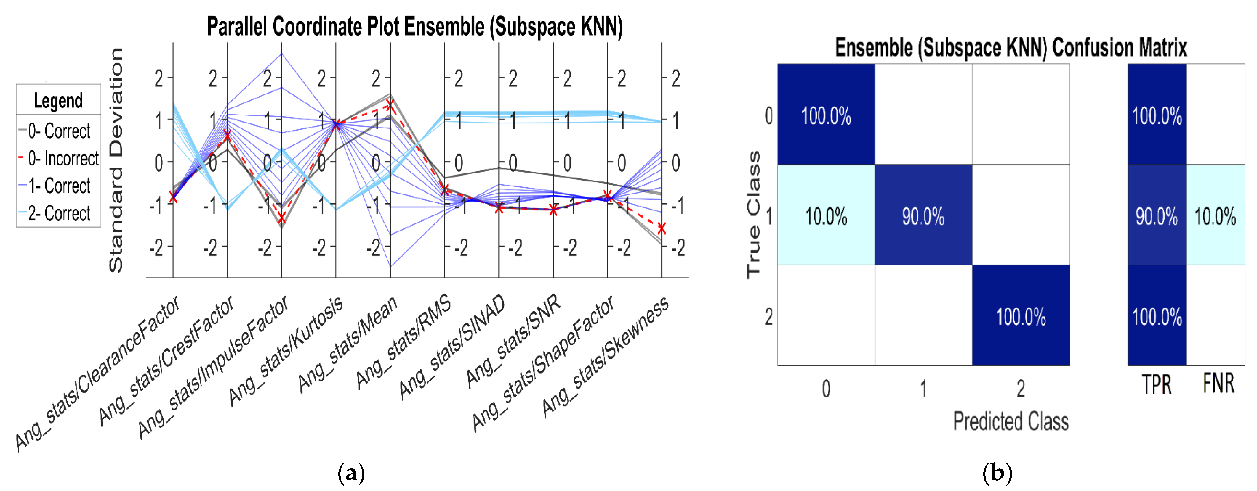
| Subspace KNN | Subspace with Nearest Neighbor | 95.8% |
Publisher’s Note: MDPI stays neutral with regard to jurisdictional claims in published maps and institutional affiliations. |
© 2022 by the authors. Licensee MDPI, Basel, Switzerland. This article is an open access article distributed under the terms and conditions of the Creative Commons Attribution (CC BY) license (https://creativecommons.org/licenses/by/4.0/).
Share and Cite
Agarwal, R.; Bhatti, G.; Singh, R.R.; Indragandhi, V.; Suresh, V.; Jasinska, L.; Leonowicz, Z. Intelligent Fault Detection in Hall-Effect Rotary Encoders for Industry 4.0 Applications. Electronics 2022, 11, 3633. https://doi.org/10.3390/electronics11213633
Agarwal R, Bhatti G, Singh RR, Indragandhi V, Suresh V, Jasinska L, Leonowicz Z. Intelligent Fault Detection in Hall-Effect Rotary Encoders for Industry 4.0 Applications. Electronics. 2022; 11(21):3633. https://doi.org/10.3390/electronics11213633
Chicago/Turabian StyleAgarwal, Ritik, Ghanishtha Bhatti, R. Raja Singh, V. Indragandhi, Vishnu Suresh, Laura Jasinska, and Zbigniew Leonowicz. 2022. "Intelligent Fault Detection in Hall-Effect Rotary Encoders for Industry 4.0 Applications" Electronics 11, no. 21: 3633. https://doi.org/10.3390/electronics11213633