Article

Improving FMCW GPR Precision through the CZT Algorithm for Pavement Thickness Measurements

1
Terahertz Science and Technology Key Laboratory of Sichuan Province, School of Electronic Science and Engineering, University of Electronic Science and Technology of China, Chengdu 610054, China
2
Department of Electronic Science and Engineering, Xinjiang University, Urumqi 830017, China
*
Author to whom correspondence should be addressed.
Electronics 2022, 11(21), 3524; https://doi.org/10.3390/electronics11213524
Submission received: 22 September 2022 / Revised: 26 October 2022 / Accepted: 27 October 2022 / Published: 29 October 2022

Abstract

:
Ground Penetrating Radar (GPR) application in road surface detection has been greatly developed in the past few decades, which enables rapid and economical estimation of pavement thickness and other physical properties in non-destructive testing (NDT) and non-contact testing (NCT). In recent years, with the rapid development of microwave and millimeter-wave solid-state devices and digital signal processors, the cost of Frequency-Modulated Continuous-Wave (FMCW) radar has dropped significantly, with smaller size and lighter weight. Thereafter, FMCW GPR is considered to be applied during pavement inspection. To improve the precision of FMCW GPR for NDT and NCT of pavement thickness, a Chirp Z-transform (CZT) algorithm is introduced to FMCW GPR and investigated in this paper. A FMCW + CZT GPR at 2.5 GHz with a bandwidth of 1 GHz was built, and laboratory and field experiments were carried out. The experimental results demonstrate that the FMCW + CZT GPR radar can obtain the sample thickness with low error and recognize subtle thickness variations. This method realizes the high precision thickness measurement of shallow asphalt pavement by FMCW radar with a narrow bandwidth pulse signal and would provide a promising low-cost measurement solution for GPR.

1. Introduction

Modern roads require pavement in good surface conditions to ensure safe and uninterrupted public transport. Effective maintenance planning during the life of the road is essential, and this includes asphalt and concrete pavement thickness measurements. Traditionally, detection of these thicknesses has been determined by coring or digging experimental pits. However, these methods suffer from many limitations, including destructiveness and traffic disruption. Engineers have begun to focus on the application of non-destructive testing (NDT) systems, which can determine the cross-section data of a measured object non-invasively [1,2]. NDT techniques can penetrate a single layer from outside the sample.
Ground Penetrating Radar (GPR) application in road surface detection has been greatly developed in the past few decades, which enables rapid and economical estimation of pavement thickness and other physical properties in NDT and non-contact testing (NCT) [3,4]. GPR has the advantage of being rapid compared to conducting test pits or borings to evaluate existing pavement conditions, and it provides continuous measurements along a pavement alignment. The traditional GPR system is an impulse radar, which works by sending electromagnetic (EM) pulses through an antenna to the road surface and then recording the reflected pulses from the internal interface. The authors of [5,6,7,8,9,10,11,12,13,14,15,16] conducted in-depth research on pavement thickness using GPR, and the thickness information of the road surface is determined by the pulse time. Since the pavement thickness is mostly less than 10 cm, the pulse peak difference is often only a few nanoseconds. Identifying such short time differences requires a high-accuracy oscilloscope, which increases measurement difficulty and cost.
Different from traditional impulse radar, Frequency Modulated Continuous Wave (FMCW) Radar is a radar system that obtains target information according to the frequency difference and phase difference between the transmitted signal and the echo signal, which have been studied in the last century [17,18]. By measurement of the frequency or phase shift of the produced beat signal, the distance difference between the transmit and receive signals can be determined [19]. Optical FMCW has been demonstrated to have several attractive features, such as high resolution, a large measurement range, and the capability of absolute measurement. In recent years, with the rapid development of microwave and millimeter-wave solid-state devices and digital signal processors, the cost of FMCW radar has dropped significantly, with smaller size and lighter weight. It has a wide range of applications in civil fields, such as collision radar, traffic flow detection, and automated driving.
Furthermore, FMCW has been demonstrated to apply to thickness measurements, such as industrial films and coatings [20,21], and ice and snow thickness measurements [22,23]. Since the frequency bandwidth directly affects the measurement accuracy, in order to obtain higher measurement accuracy, ultra-wideband millimeter-wave and terahertz radars have been studied. For example, the measurement accuracy of the FMCW GPR system in [24,25,26] can reach the micron level. But asphalt pavement information research based on FMCW GPR is still limited. Simulations of asphalt pavement thickness measurements were studied in [27] and the dielectric properties of asphalt pavements were studied in [28] using FMCW GPR. However, pavement thickness is not systematically measured.
Previous studies show that the measurement accuracy of FMCW GPR is positively correlated with the operating frequency and bandwidth. However, the EM wave with a high frequency and wide bandwidth would get high transmission loss during EM wave propagation in the ground. The signal-to-noise ratio would be low, and the effective detection distance would be shallow. On the other hand, for EM waves with low frequency and narrow bandwidth, although the detection distance could be prolonged, the resolution and accuracy would be low. Therefore, an important topic of FMCW GPR research is obtaining deep detection and high resolution. In this paper, a Chirp Z-transform (CZT) algorithm is introduced to replace the Fast Fourier Transform (FFT) used in traditional FMCW GPR. CZT is a spectrum calculation method based on spiral sampling, which can obtain high-precision spectra with low sampling points in the frequency band of interest [29,30]. In this investigation, a compact low-frequency narrow-band FMCW GPR for asphalt pavement thickness measurement is being built. The experiment results show the CZT algorithm could sufficiently improve measurement accuracy under the limited sampling rate compared to conventional FFT. This method can be used to measure asphalt pavement thickness in applications. The low frequency and narrow band signals would also reduce the hardware requirements and cost.

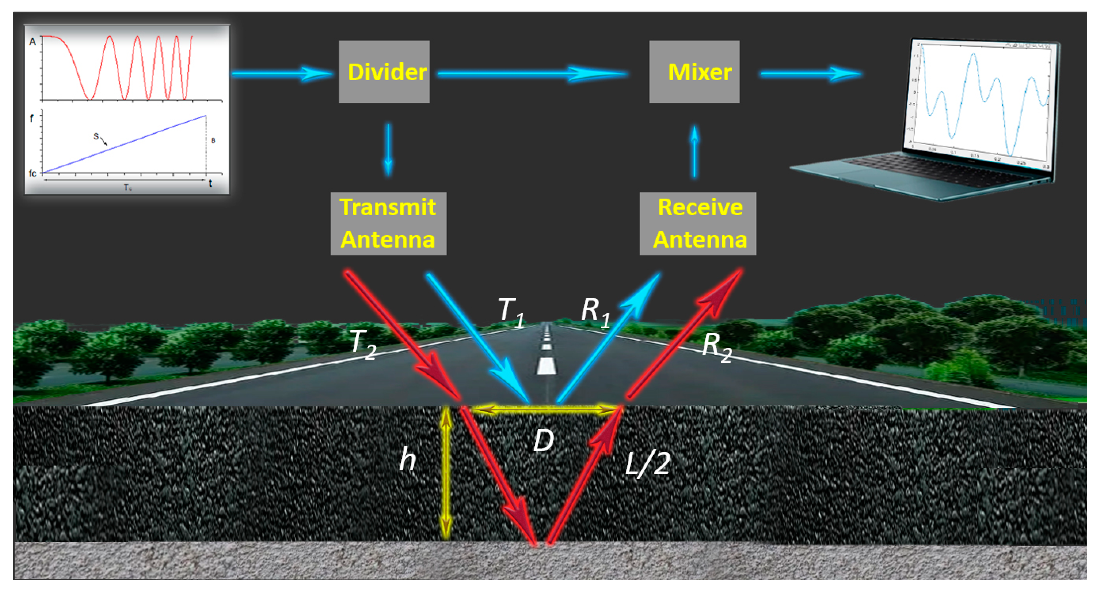
2. Principle and System Scheme

2.1. FMCW GRP Measurement System

The principle of the investigated FMCW GRP measurement system is shown in Figure 1. A chirp signal with a period, slope, and bandwidth of TC, S, and B, respectively, is connected to the mixer and the transmit antenna through the power divider. The emission signal is divided into two parts, T1 and T2, in which T1 reaches the upper surface of the tested sample, and the reflected signal is R1. After T2 passes through the sample to be tested, it is reflected on the lower surface, and the reflected signal is R2. R1 and R2 are two sinusoidal signals of different frequencies, which are superimposed and mixed with the transmitted signal, and theoretically generate down-converted signals of two frequencies. After spectrum analysis, the lower frequency is f1, the higher frequency is f2, and the frequency difference is Δf = f2 − f1.
When the transmitted signal is vertically incident, the thickness h formula can be expressed as:
h = L 2 = T c Δ f c 2 ε B
where L is the distance the microwave travels in the object, TC is the period of the chirp pulse, Δf is the difference between two frequency peaks, c is the speed of light in free space, ε is the sample relative permittivity, and B is the bandwidth of the chirp. If the thickness is known, the dielectric constant of the sample can also be obtained by conversion.
When the transmitting antenna is relatively far from the receiving antenna, Formula (1) needs to be corrected as:
h = ( L 2 ) 2 ( D 2 ) 2
where D is approximately the distance between the two antennas. The distance the signal travels in the air can be expressed as:
S = T c f 1 c 2 ε 0 B
where ε0 is the relative permittivity of air. Formula (3) can calculate the distribution of the surface layer of the measured object.

2.2. Chirp-z Transformation

It can be seen from Formula (1) that after the radar system is determined, B and Tc are both constants. Therefore, the accuracy of the measurement is related to the frequency difference Δf, and the two down-conversion frequencies of the Intermediate Frequency (IF) signal are the key parameters of the measurement. FFT is a commonly used algorithm for calculating frequency, which can quickly calculate all N-point discrete Fourier transform (DFT) values, that is, all equally spaced sample values of the Z transform on the unit circle of the Z plane. It is well known that the DFT of the sequence is the Z transform of X(n) sampling at N points on the unit circle at equal intervals, and the sampling interval is e j 2 π N . Additionally, DFT is the spectrum uniformly distributed over N points on the unit circle of the Z plane. When X(n) is a short-time sequence, the frequency resolution 2 π N obtained by DFT will be extremely low. Nevertheless, high sampling points will lead to an increase in the amount of computation and cost. However, FMCW radars often only require a part of the spectrum rather than calculating Z-transformed samples for the entire unit circle. The CZT transform is a spiral sampling calculation method that does not sample on the unit circle. The frequency resolution will be greatly improved by calculating the part of the spectrum of interest. The CZT transform of the sequence formula can be expressed as:
C Z T [ X ( n ) ] = A 0 W 0 k e j ( θ + k φ )      k [ 0 , N 1 ]
where A0, W0, θ, and ϕ are all constants defined by computational requirements. When
A 0 = W 0 = 1 ,   θ = 0 ,   φ = e j 2 π N
then the CZT transform is the same as the DFT result.

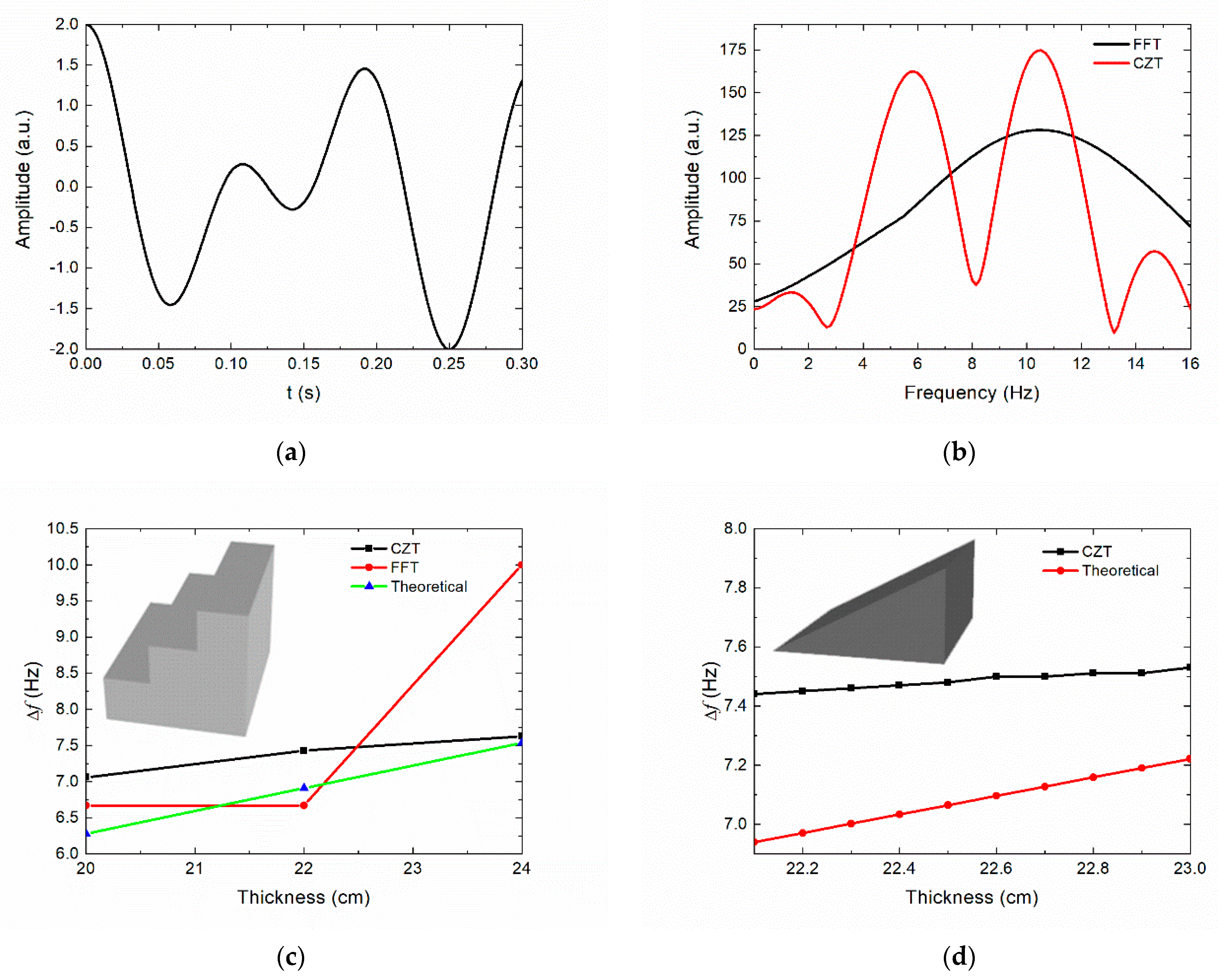
2.3. Numerical Simulation
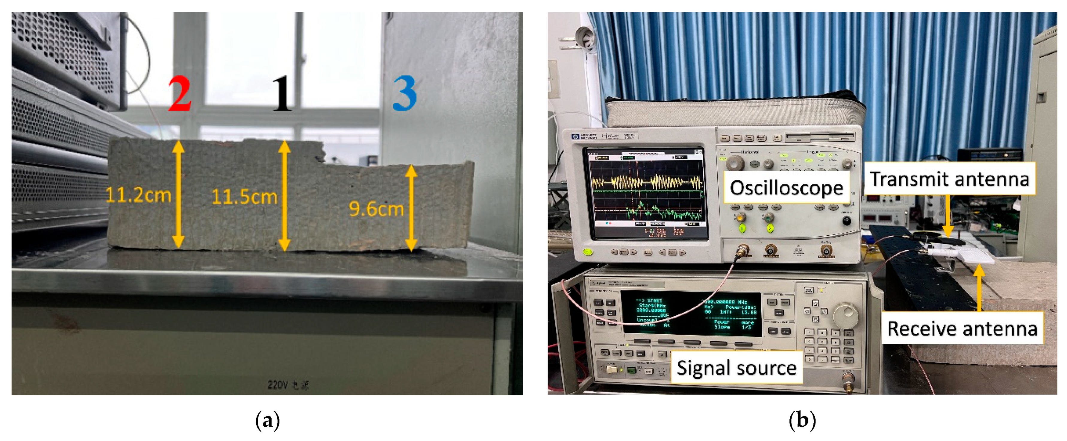
As mentioned in the introduction, the accuracy of the two algorithms, FFT and CZT, was compared and analyzed in this section, and the performance of the chirp signal in thickness measurement using a low number of sampling points was simulated by a MATLAB code. An IF signal with a period of 0.3 s and two frequencies was created, whose frequencies are 6 Hz and 10 Hz, respectively, as shown in Figure 2a. Figure 2b shows the spectrum analysis of the IF signal by the two algorithms. It can be seen that the spectrum analysis obtained using the FFT algorithm can only identify one frequency, which is 10 Hz. In contrast, the spectral peaks calculated with CZT are 5.7 Hz and 10.4 Hz, respectively. The computational accuracy of FFT was limited by the number of sampling points, while CZT significantly improved the frequency resolution. The thicknesses of the two sample models were simulated and obtained, and their thicknesses increased gradiently and linearly, which can be observed in Figure 2c,d. The period of the simulated emission chirp signal was 0.3 s, the bandwidth was 1 GHz from a range of 2–3 GHz, the relative permittivity of the sample was 2, and the signal was assumed to be normal incidence. Figure 2c shows the results of the first sample calculated using FFT and CZT simulations with thicknesses of 20 cm, 22 cm, and 24 cm and compared with the theoretical calculations. It turns out that the results obtained by FFT may deviate far from the true value, while the calculated results of CZT are closer. Figure 2d presents the numerical simulation of a sample with a linear increase in thickness from 22 cm to 23 cm. The simulation results show that the error is less than 0.5 Hz and the frequency resolution is 0.2 Hz. A thickness difference of 6.4 mm can be identified by substituting 0.2 Hz into Formula (1) and the frequency resolution increases linearly with the relative permittivity of the sample.

3. Experiments

A concrete model with an uneven thickness was fabricated to verify the measurement accuracy of the proposed FMCW radar. The model was divided into three layers, the measured thicknesses were 11.5, 11.2, and 9.6 cm, and the relative permittivity was 12, as shown in Figure 3a. It is worth noting that the model with non-uniform thickness facilitates the study of the measurement sensitivity of the proposed FMCW radar. Figure 3b shows the completed FMCW radar. The signal source is an Agilent-83624B, the output chirp signal bandwidth is 1 GHz from a range of 2–3 GHz, and the period is 0.3 s, which is consistent with the simulation signal. The signal source connects half of the chirped signal to the transmit antenna through a frequency divider and the other half to the mixer. The transmitted signal irradiated the upper and lower surfaces of the model, and the two echo signals were received by the receiving antenna through the amplifier and then transmitted to the other end of the mixer. Then, the mixer outputs the IF signal mixed by the original chirp signal and the reflected signal. Finally, the IF signal is stored by the oscilloscope and exported into a computer for CZT calculation.
The antennas were mounted on a special metal platform. Therefore, the three IF signals of the concrete model could be acquired by translating the platform or the antennas, and the antennas were kept at the same level to facilitate the analysis of the thickness variation of the sample. In order to verify the performance of the built FMCW GPR for thickness measurement in construction projects, the thickness of the laboratory wall was evaluated using the same method by aligning the antennas to the wall. In the field experiment, an uneven pavement outside the School of Electronic Science and Engineering at the University of Electronic Science and Technology of China was selected for the thickness evaluation of the asphalt pavement. All the results will be presented in the next section.

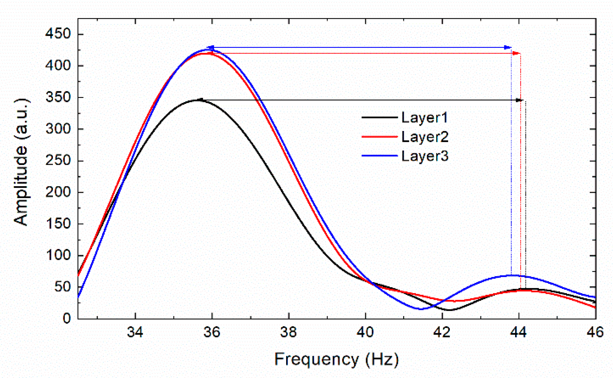
4. Results and Discussion

In the concrete model experiment, the spectrum of the three IF signals obtained by measuring concrete through CZT calculations is shown in Figure 4. Two spectral peaks of the three IF signals can be clearly seen, and the Δf between the two frequency peaks decreases significantly with the decrease of the thickness. The three Δf are 8.70, 8.58, and 7.86 Hz, respectively. Approximate treatment is vertical incidence and reflection, and the concrete thicknesses calculated by Formula (1) were 11.00, 10.85, and 9.93 cm, respectively, with a maximum error of 0.5 cm. The experimental results show that the proposed FMCW radar has less error in thickness measurement and has high sensitivity to identify slight thickness variations of the sample. The reason for the higher frequency of the spectrogram is that the transmission line extends the transmission distance of the signal, which does not affect the measurement of the sample thickness. If the distance from the antenna to the sample needs to be measured, the entire spectrum needs to be shifted to the left by 34.51 to correct the error caused by the transmission line.
In the laboratory experiment, the proposed FMCW radar measured the thickness of the laboratory wall, which has a thickness of 25 cm and a relative permittivity of 5.06. A wooden board was placed behind the wall to obtain the reflected signal, and the time domain diagram of the measured IF signal is shown in Figure 5a. Although the noise signal and antenna side sidelobes caused some distortion, the time domain plot shows a relatively clear dual-frequency sinusoidal signal, which has minimal impact on the spectrum analysis. The spectrum obtained by the CZT algorithm is shown in Figure 5b. The first and second spectrum peaks are intensely clear, and the Δf is 12.348 Hz. Assuming that the signal is vertically incident and received, the wall thickness calculated by Formula (1) was 24.62 cm with an error of 3.8 mm. Therefore, the constructed FMCW radar was competent for thickness measurement of construction projects.
In a field experiment, an uneven ground was measured with a measurement length of 3 m, and a total of 50 sets of data were recorded every 6 cm. A total of 3 of 50 experimental spectrogram data and measurement locations are shown in Figure 6a. It is clear from the experimental data that the two spectral peaks and f vary with thickness. Since the road surface is uneven, the transceiver antennas were placed on the same horizontal plane, in order to facilitate the analysis of the thickness variation of the asphalt pavement and the distance variation between the antennas and the road surface. The distance between the antenna and the ground was calculated using Formula (3), and the thickness of the asphalt pavement was calculated using Formula (2). The 2D imaging is shown in Figure 6b, where asphalt pavement thickness varies linearly between 6 and 7 cm. It can be seen that the road has undergone great deformation after many years of construction, and FMCW + CZT GPR has accurately measured the thickness and distribution of the asphalt pavement. Although the results of some points were less than perfect, NDT and NCT pavement thickness had been achieved.

5. Conclusions

To improve the precision of FMCW GPR for NDT and NCT of asphalt pavement thickness, a CZT algorithm is introduced to FMCW GPR and investigated in this paper. To demonstrate the proposal, a FMCW + CZT GPR at 2.5 GHz with a bandwidth of 1 GHz was built, and laboratory and field experiments were carried out. In laboratory experiments, the built FMCW GPR was able to evaluate the thickness of the fabricated concrete blocks with an error of 0.5 cm and to identify small thickness variations. In addition, the error in measuring wall thickness was only 3.8 mm. The thickness of uneven asphalt pavement is also clearly demonstrated in the field experiment of pavement thickness. Experimental results show that, at the above EM wave parameters, the measurement accuracy by the CZT algorithm can reach 5 mm, while due to the limitation of sampling rate and bandwidth, the measurement error of FFT is 20 mm or even impossible to measure. The experimental results also show good agreement with the theoretical analysis. This investigation demonstrates that, through an appropriate algorithm, the detection depth and precision can be obtained simultaneously. The presented compact FMCW + CZT GPR would be used not only for asphalt pavement thickness measurement but also for walls and other building material thickness measurement. Furthermore, this investigation would provide an approach to improve the precision of FMCW radar for other thickness measurement applications and reduce the cost of the measurement system.

Author Contributions

Conceptualization, T.H. and W.F.; methodology, W.F.; software, T.H. and Q.Z.; formal analysis, T.H. and C.Z.; data curation, T.H. and D.L.; writing—original draft preparation, T.H.; writing—review and editing, W.F.; project administration, Y.Y.; funding acquisition, W.F. and Y.Y. All authors have read and agreed to the published version of the manuscript.

Funding

This work was supported by the National Key Research and Development Program of China under 2019YFA0210202 and the National Natural Science Foundation of China under Grants 61971097 and 62111530054.

Data Availability Statement

The data presented in this study are available on request from the corresponding author.

Conflicts of Interest

The authors declare no conflict of interest.

References

  1. Plati, C.; Loizos, A.; Gkyrtis, K. Assessment of Modern Roadways Using Non-destructive Geophysical Surveying Techniques. Surv. Geophys. 2020, 41, 395–430. [Google Scholar] [CrossRef]
  2. Elseicy, A.; Alonso-Díaz, A.; Solla, M.; Rasol, M.; Santos-Assunçao, S. Combined Use of GPR and Other NDTs for Road Pavement Assessment: An Overview. Remote Sens. 2022, 14, 4336. [Google Scholar] [CrossRef]
  3. AL-Qadi, I.L.; Lahouar, S. Measuring layer thicknesses with GPR—Theory to practice. Constr. Build. Mater. 2005, 19, 763–772. [Google Scholar] [CrossRef]
  4. Al-Qadi, I.L.; Leng, Z.; Lahouar, S.; Baek, J. In-Place Hot-Mix Asphalt Density Estimation Using Ground-Penetrating Radar. Transp. Res. Rec. 2010, 2152, 19–27. [Google Scholar] [CrossRef] [Green Version]
  5. Hu, J.; Vennapusa, P.K.R.; White, D.J.; Beresnev, I. Pavement thickness and stabilised foundation layer assessment using ground-coupled GPR. Nondestruct. Test. Eval. 2016, 31, 267–287. [Google Scholar] [CrossRef]
  6. Guo, C. Extraction of the Pavement Permittivity and Thickness From Measured Ground-Coupled GPR Data Using a Ground-Wave Technique. IEEE Geosci. Remote Sens. Lett. 2017, 14, 399–403. [Google Scholar] [CrossRef]
  7. Cui, L. FDTD Simulation for Moisture Asphalt Pavement Thickness and Density Estimation Utilizing Ground Penetrating Radar. KSCE J. Civ. Eng. 2021, 25, 3336–3345. [Google Scholar] [CrossRef]
  8. Ožbolt, M.; Rukavina, T.; Domitrović, J. Comparison of the Pavement Layers Thickness Measured by Georadar and Conventional Methods—Examples From Croatia. Balt. J. Road Bridge Eng. 2012, 7, 30–35. [Google Scholar] [CrossRef]
  9. De Coster, A. Evaluation of pavement layer thicknesses using GPR: A comparison between full-wave inversion and the straight-ray method. Construction and Building Materials 2018, 168, 91–104. [Google Scholar] [CrossRef]
  10. Bezina, Š. Spatial Representation of GPR Data—Accuracy of Asphalt Layers Thickness Mapping. Remote Sens. 2021, 13, 864. [Google Scholar] [CrossRef]
  11. Wang, S.; Zhao, S.; Al-Qadi, I.L. Real-Time Density and Thickness Estimation of Thin Asphalt Pavement Over-lay During Compaction Using Ground Penetrating Radar Data. Surv. Geophys. 2020, 41, 431–445. [Google Scholar] [CrossRef]
  12. Puente, I. Validation of mobile LiDAR surveying for measuring pavement layer thicknesses and volumes. NDT E Int. 2013, 60, 70–76. [Google Scholar] [CrossRef]
  13. Qiu, Z.; Zhao, Z.; Chen, S.; Zeng, J.; Huang, Y.; Xiang, B. Application of an Improved YOLOv5 Algorithm in Real-Time Detection of Foreign Objects by Ground Penetrating Radar. Remote Sens. 2022, 14, 1895. [Google Scholar] [CrossRef]
  14. Hamdan, H.; Economou, N.; Vafidis, A.; Bano, M.; Ortega-Ramirez, J. A New Approach for Adaptive GPR Diffraction Focusing. Remote Sens. 2022, 14, 2547. [Google Scholar] [CrossRef]
  15. Qi, S.; Li, G.; Chen, D.; Chai, M.; Zhou, Y.; Du, Q.; Cao, Y.; Tang, L.; Jia, H. Damage Properties of the Block-Stone Embankment in the Qinghai–Tibet Highway Using Ground-Penetrating Radar Imagery. Remote Sens. 2022, 14, 2950. [Google Scholar] [CrossRef]
  16. Oliveira, R.J.; Caldeira, B.; Teixidó, T.; Borges, J.F.; Carneiro, A. Increasing the Lateral Resolution of 3D-GPR Datasets through 2D-FFT Interpolation with Application to a Case Study of the Roman Villa of Horta da Torre (Fronteira, Portugal). Remote Sens. 2022, 14, 4069. [Google Scholar] [CrossRef]
  17. Skolnik, M.I. Introduction to Radar Systems, 3rd ed.; McGraw-Hill: New York, NY, USA, 2001. [Google Scholar]
  18. Culshaw, B.; Giles, I. Frequency modulated heterodyne optical fiber Sagnac interferometer. IEEE J. Quantum Electron. 1982, 18, 690–693. [Google Scholar] [CrossRef]
  19. Surendra, P. FMCW—Radar Design. IETE J. Res. 2019, 65, 576–577. [Google Scholar] [CrossRef]
  20. Schreiner, N.S.; Baccouche, B.; Sauer-Greff, W.; Urbansky, R.; Friederich, F. In Proceedings of the High-Resolution FMCW Millimeter-Wave and Terahertz Thickness Measurements 2017 European Radar Conference (EURAD), Nuremberg, Germany, 10–12 October 2017. [CrossRef]
  21. Chopard, A. Terahertz waves for contactless control and imaging in aeronautics industry. NDT E Int. 2021, 122, 102473. [Google Scholar] [CrossRef]
  22. Ayhan, S. Millimeter-Wave Radar Sensor for Snow Height Measurements. IEEE Trans. Geosci. Remote Sens. 2017, 55, 854–861. [Google Scholar] [CrossRef]
  23. Pomerleau, P. Low Cost and Compact FMCW 24 GHz Radar Applications for Snowpack and Ice Thickness Measurements. Sensors 2020, 20, 3909. [Google Scholar] [CrossRef] [PubMed]
  24. Bhutani, A. The Role of Millimeter-Waves in the Distance Measurement Accuracy of an FMCW Radar Sensor. Sensors 2019, 19, 3938. [Google Scholar] [CrossRef] [PubMed] [Green Version]
  25. Bhutani, A.; Marahrens, S.; Kretschmann, M.; Ayhan, S.; Scherr, S.; Göttel, B.; Pauli, M.; Zwick, T. Applications of radar measurement technology using 24 GHz, 61 GHz, 80 GHz and 122 GHz FMCW radar sensors. Tm—Tech. Mess. 2022, 89, 107–121. [Google Scholar] [CrossRef]
  26. Thomas, S.; Bredendiek, C.; Pohl, N. A SiGe-Based 240-GHz FMCW Radar System for High-Resolution Measurements. IEEE Trans. Microw. Theory Tech. 2019, 67, 4599–4609. [Google Scholar] [CrossRef]
  27. Huaqing, L.; He, Z. Study on Signal Processing of FMCW Ground Penetrating Radar. In Proceedings of the 2009 International Conference on Measuring Technology and Mechatronics Automation, Zhangjiajie, China, 11–12 April 2009. [Google Scholar] [CrossRef]
  28. Liu, C.R.; Li, J.; Gan, X.; Xing, H.; Chen, X. Pavement thickness measurement using FM-CW radar. Subsurface and Surface Sensing Technologies and Applications III 2001. Proc. SPIE 2001, 4491, 159–166. [Google Scholar] [CrossRef]
  29. Rabiner, L.; Schafer, R.; Rader, C. The chirp z-transform algorithm. IEEE Trans. Audio Electroacoust. 1969, 17, 86–92. [Google Scholar] [CrossRef]
  30. Qin, M.; Li, D.; Tang, X.; Zeng, C.; Li, W.; Xu, L. A Fast High-Resolution Imaging Algorithm for Helicopter-Borne Rotating Array SAR Based on 2-D Chirp-Z Transform. Remote Sens. 2019, 11, 1669. [Google Scholar] [CrossRef]
Figure 1. FMCW radar measurement principle.
Electronics 11 03524 g001
Figure 2. FFT and CZT algorithm simulation: (a) An IF signal with frequencies of 6 and 10 Hz. (b) Spectral analysis of IF signals by FFT and CZT algorithms. (c) FFT and CZT calculations for samples with thicknesses of 20, 22, and 24 cm. (d) CZT calculates samples with a linear thickness growth from 22 to 23 cm.
Electronics 11 03524 g002
Figure 3. (a) Concrete model with three layers of thickness. (b) The proposed FMCW radar is used for model thickness measurement.
Electronics 11 03524 g003
Figure 4. The spectrum diagram obtained by the CZT algorithm in evaluating concrete thickness.
Electronics 11 03524 g004
Figure 5. (a) The IF signal diagram after detecting a wall. (b) The spectrum diagram of the IF signal obtained by the CZT algorithm.
Electronics 11 03524 g005
Figure 6. (a) Three spectrogram datasets calculated by CZT (b) Two-dimensional imaging of asphalt pavement.
Electronics 11 03524 g006
Publisher’s Note: MDPI stays neutral with regard to jurisdictional claims in published maps and institutional affiliations.

