Article

Performance of Cooperative Relay NOMA with Large Antenna Transmitters

by
Samuel Tweneboah-Koduah
1,*,
Emmanuel Ampoma Affum
2,
Kwame Agyemang-Prempeh Agyekum
2,
Sunday Adeola Ajagbe
3,4 and
Matthew O. Adigun
4
1
Department of Computer and Electrical Engineering, University of Energy and Natural Resources, Sunyani P. O. Box 214, Ghana
2
Department of Telecommunication Engineering, Kwame Nkrumah University of Science and Technology, Kumasi P. O. Box 1279, Ghana
3
Department of Computer Engineering, Ladoke Akintola University of Technology, Ogbomoso 210214, Nigeria
4
Department of Computer Science, University of Zululand, Kwadlangezwa 3886, South Africa
*
Author to whom correspondence should be addressed.
Electronics 2022, 11(21), 3482; https://doi.org/10.3390/electronics11213482
Submission received: 28 September 2022 / Revised: 17 October 2022 / Accepted: 20 October 2022 / Published: 26 October 2022
(This article belongs to the Special Issue Massive MIMO Technology for 5G and Beyond)

Abstract

:
The potential of the Non-Orthogonal Multiple Access (NOMA) approach for wireless communications in the fifth generation (5G) and beyond can not be underestimated. This is because users with favorable channel conditions can serve as relays to improve system performance by employing Successive Interference Cancellation (SIC). Lately, the combination of NOMA and the cooperative relay has attracted the interest of researchers. The analysis of cooperative relay NOMA (CR-NOMA) with a massive multiple-input multiple-output (mMIMO) system is mainly based on theoretical channel models such as the correlated-based stochastic channel model (CBSM) even though the geometric-based stochastic channel model (GBSM) has been found to provide better, practical and realistic channel properties. This, in our view, is due to computational challenges. Again, the performance of CR-NOMA systems using the GBSM channel model with large antenna transmitters and network coding schemes has attracted little attention in academia. Therefore, the need to study mMIMO CR-NOMA that considers channel properties such as path-loss, delay profile and tilt angle has become vital. Furthermore, the co-existing of large antenna transmitters with coding schemes needs further investigation. In this paper, we study the performance of a two-stage mMIMO CR-NOMA network where the transmitter is represented as a uniform rectangular array (URA) or cylindrical array (CA). The communication channel from the transmitter (TX) to the user equipment (UE) through a relay station (RS) is modeled with a 3GPP’s three-dimensional (3D) GBSM mMIMO channel model. To improve the analytical tractability of 3D GBSM, we defined the antenna element location vectors using the physical dimension of the antenna array and incorporated them into the 3D channel model. Bit-error rates, achievable rates and outage probabilities (OP) are examined using amplify-and-forward (AF) and decode-and-forward (DF) coding schemes. Results obtained show with fixed power allocation and SNR of 20 dB, far or weak users can attain a high achievable rate using DF and URA. Again, from the results, the combination of AF and CA presents better outage probabilities. Finally, the results indicate that the performance difference between CBSM and GBSM is marginal, even though the proposed 3D GBSM channel model has a higher degree of random parameters and computational complexities.

1. Introduction

The design of 5G is to fundamentally fulfil the emerging requirements of wireless communication, such as high spectral and energy efficiency, low latency, massive device connectivity, high data rate and ultrahigh reliability [1,2,3]. Therefore, this requires a multiple access technology that meets the network capacity within the limited radio spectrum [4,5,6]. NOMA technique is considered for 5G networks to improve system performance, high reliability, increased system capacity and coverage area [7,8,9]. NOMA, unlike orthogonal multiple access (OMA), uses the same time, code and or radio frequency resources to provide services to multiple users. This is done by introducing controlled interference through non-orthogonal resource allocation [10]. Most importantly, it supports large numbers of connections and high-congestion transmission [11]. The basic operation of NOMA is to superimpose multiple signals at the transmitter in the power domain. As shown in Figure 1, at the Base Station (BS), data from various users are superimposed on top of one another over the same time/frequency/code resource block. The BS uses a power allocation generator to assign different power levels to each user within resource block. The superimposed signal, s ( t ) , is transmitted through a fading channel with additive white Gaussian noise (AGWN) to the receiving user equipment (UE). The Gaussian channel’s output is the sum of the input signal and an independent identically distributed noise signal from a Gaussian distribution of variance N, that may be produced by the receiver electronics [12]. In addition, at the UE, NOMA employs interference cancellation (SIC) method to improve network performance, to minimize interference and separate multiplexed users [13]. In NOMA, the weak user treats a strong user’s signals as noise and directly decodes its signal [14]. The strong user on the other hand uses SIC to detect and decode their signals [7]. Additionally, weak users receive more power than strong users due to interference and poorer channel gains [15]. This is intended to maximize weak user transmission rate, experience and fairness [14].
The concept of CR-NOMA was established in [16] to increase the performance of cell edge users. In CR-NOMA several network coding schemes are introduced to secure the quality of service to weak users in the communication network [15]. This is to minimize interference and enhance performance. These schemes are decode-and-forward, compress-and-forward, amplify-and-forward, and compute-and-forward.

1.1. Review of Existing Works and Motivation

1.1.1. 5G Massive MIMO Channel Models

To assess the performance of 5G wireless communication systems, two types of channel models are commonly used; correlation-based stochastic models (CBSMs) and geometry-based stochastic models (GBSMs) [17,18]. The former has a lesser level of complexity and is mostly used to analyze the theoretical performance of MIMO systems [17,19].
However, the accuracy of a realistic MIMO system is restricted, and modeling wireless channels with nonstationary phenomena and spherical wave effects is challenging [17,19,20]. In contrast, GBSM has increased processing complexity, however, it can correctly represent true channel parameters and is better appropriate for mMIMO channel models [17]. GBSM incorporates channel properties such as path-loss, delay profile, tilt angle, angle of arrivals, etc into the channel modeling for better performance evaluation [20,21,22].

1.1.2. Performance of CR-NOMA with CBSM Channel Model

The review of performance of CR-NOMA using AF/DF coding schemes is presented in this section. As previously stated, the performance of CR-NOMA has been extensively studied utilizing various network coding schemes and channel characteristics [23,24,25,26,27]. The use of a relay in NOMA system is to improve system performance and extend the network coverage [28]. The effect of various network coding schemes on the performance of CR-NOMA has been studied in [21,29]. In order to improve reliability, enhance the spectrum, power effectiveness and network connectivity, certain network terminals interact and aid one another by using the broadcast aspect of the wireless connections [30]. In CR-NOMA, users or devices with poor channel conditions, who often suffer from power losses at the cell edge, can be assisted by other users or devices with strong channel conditions by serving as transmission relays. This can greatly improve the reliability of the weak user’s reception. There are two well-known network coding schemes: amplify-and-forward (AF) and decode-and-forward (DF) coding schemes [31,32]. The AF coding scheme relay simply amplifies and forwards a scaled version of its observation to the destination [23,33,34,35,36]. A CSI-assisted AF relay exploits instantaneous CSI of source-to-relay link to adjust its gain which has superior performance over the fixed gain AF relay has been studied in [37,38,39,40,41,42]. DF coding scheme relay, on the other hand, decodes the received signal first before re-transmitting the decoded signal to the destination [23]. Others such as compress-and-forward (CF) and computer-and-forward(CpF) have been studied in [15,40,43,44,45,46,47,48,49] respectively. With the CF approach, the signal is compressed and sent to the target location(s), whereas with the CpF however does not requires CSI and exploits signal couplings produced by the channel to remove noise noise and mitigate interference at the relays thereby reducing the number of relays required. Resource allocation optimization has been analyzed using the above coding schemes in [45,50,51,52,53,54,55,56,57,58,59,60] in order to improve CR-NOMA performance. Majority of the CR-NOMA performance evaluations (OP, achievable rate, BER, etc.) stated above have been limited to CBSM channel models. Table 1, presents a summary of CR-NOMA performance using CBSMs with AF/DF coding schemes. Figure 2 presents the CR-NOMA model that used and studied in the above studies, where the channel between the transmitter, relay and the users is modeled as CBSM. To improve system spectral efficiency and reduce challenges in channel state information (CSI) acquisition, CR-NOMA with MIMO and mMIMO have been studied in [47,61]. In [47], the authors considered the Saleh-Valenzuela millimeter-wave channel model for beamforming analysis, and no network coding schemes were considered. Again the analysis focused on user relay and not dedicated relay. The authors in [61], studied the application of relay to mMIMO NOMA. However, the analysis was based on CBSM. They proposed a general framework for a multiple-relay aided massive NOMA system. At the TX, the authors considered circular array for the analysis which is not a typical antenna array typologies for massive MIMO systems according to [17].

1.2. Motivation

From the above literature, the techniques and analysis that have been used to improve system performance of CR-NOMA have predominantly been restricted to only CBSM [62,63,64,65,66,67,68,69,70,71,72,73,74,75,76].
CBSM is basically used for theoretical analysis and has less accuracy for real-world mMIMO systems due to the nonstationary phenomenon and spherical effects [17,89]. The best we can tell is that authors in [47] have analyzed CR-NOMA performance using GBSM based on Saleh-Valenzuela channel model. For mMIMO systems, there are several typical antenna array configurations. These include linear antenna array, rectangular antenna array, spherical antenna array, distributed antenna array and cylindrical antenna array [17]. With CR-NOMA, only linear antenna array has been examined so far in [61].
Based on the above, the motivation of this work is to address the missing gap in the literature on CR-NOMA concerning the adoption of 3GPP 3D GBSM channel model with large antenna transmitters such as URA and CA. Our research aims to provide solutions to the following research challenges to fulfill future demands of wireless communication systems: (1) What effect will the large antenna transmitters (CA or URA) modeling have on CR-NOMA system’s performance? (2) How will mMIMO CR-NOMA work when the user, the dedicated relay, and transmitter all use the 3D GBSM channel model? (3) How will the coexistence of large antenna transmitters, 3D GBSM channel models, and coding schemes affect performance of CR-NOMA? (4) what coding scheme and large antenna combination will provide the superior performance when using the GBSM channel model for mMIMO CR-NOMA regarding outage probability, achievable rate, and bit-error-rate (BER)?

1.3. Contribution of the Work

We consider a two-stage downlink network system model with a dedicated relay. We use the 3GPP and WINNER+ models that follow the GBSM approach in [90,91,92] and provide a 3D GBSM channel model [93,94] when the transmitter is either URA or CA. We use the channel model in a CR-NOMA system where the transmitter’s antenna is a massive antenna array system. We analyse the performance of the proposed system when the RS uses either AF or DF network coding scheme. The reason is that research in [21,95] shows that a significant component of energy is emitted in the elevation of the WINNER+ and 3GPP models. As a result, specifying propagation pathways in azimuth alone does not improve performance [95]. Furthermore, the WINNER+ and 3GPP models include the antenna boresight’s elevation angle in the channel equation. We use URA and CA because their radiated MIMO signals can be adjusted in 3D space to boost system capacity [21]. Again, a massive antenna array can reduce clutter by using scanning acceleration and a space-time signal. Furthermore, it permits the creation of concentrated beams in any horizontal direction [21]. To reduce the computational complexity of the 3D GBSM channel model, we define the antenna element location vector using the physical dimension of the antenna array and incorporate it into the 3D channel model [21,96,97]. To enhance the performance of the proposed mMIMO CR-NOMA system, two coding schemes, AF and DF, are used with the channel model. The results present the performances of the combination of coding schemes and large antenna transmitters regarding achievable rate, outage probability and Bit-error rate (BER).
Again, to fill the gap in the above literature on the CR-NOMA system concerning the adoption of 3GPP’s 3D GBSM channel model with large antenna transmitters, this paper aims to assess the system usage performances using the proposed channel model. For clarity, the major contributions and objectives of the paper are:
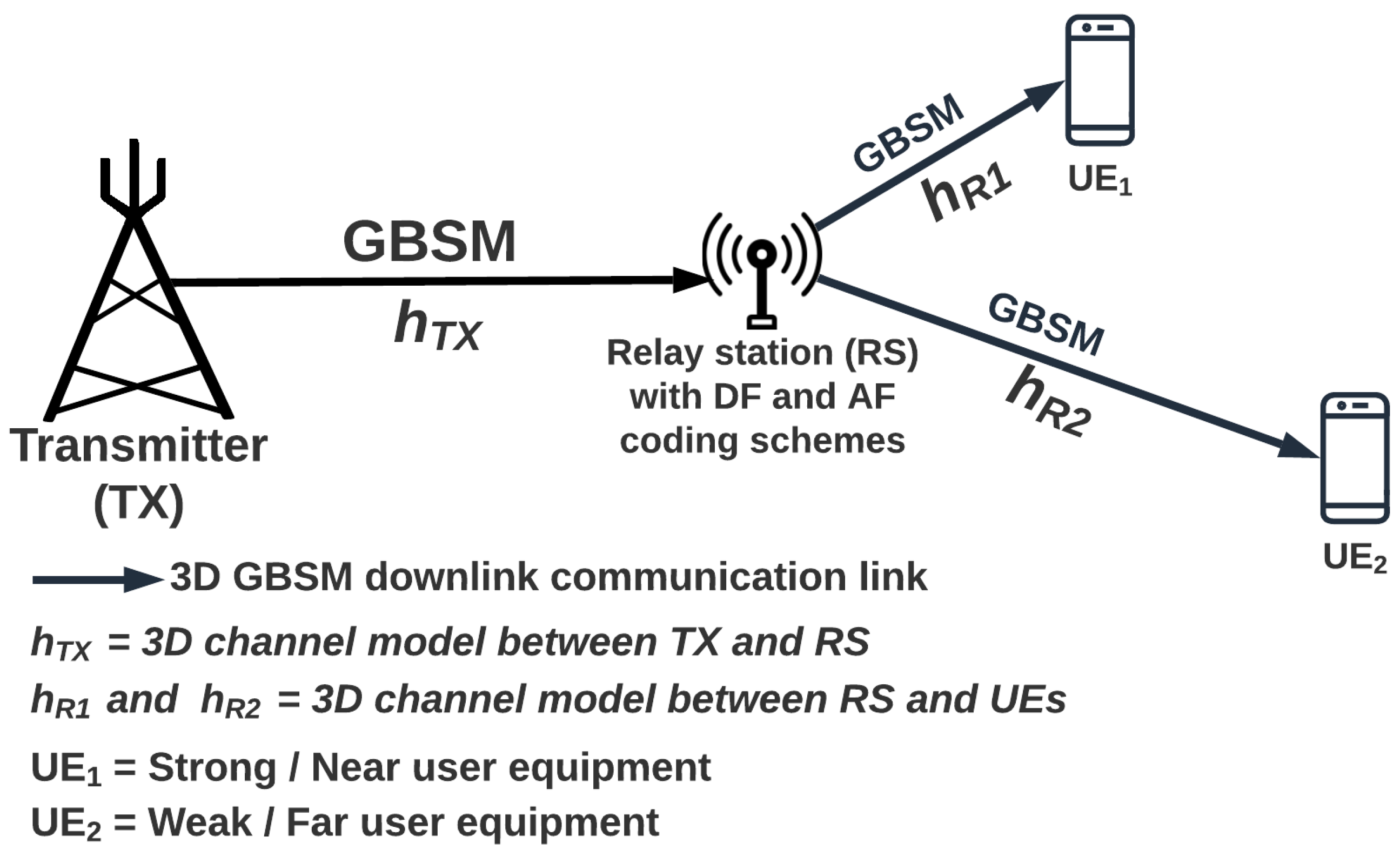
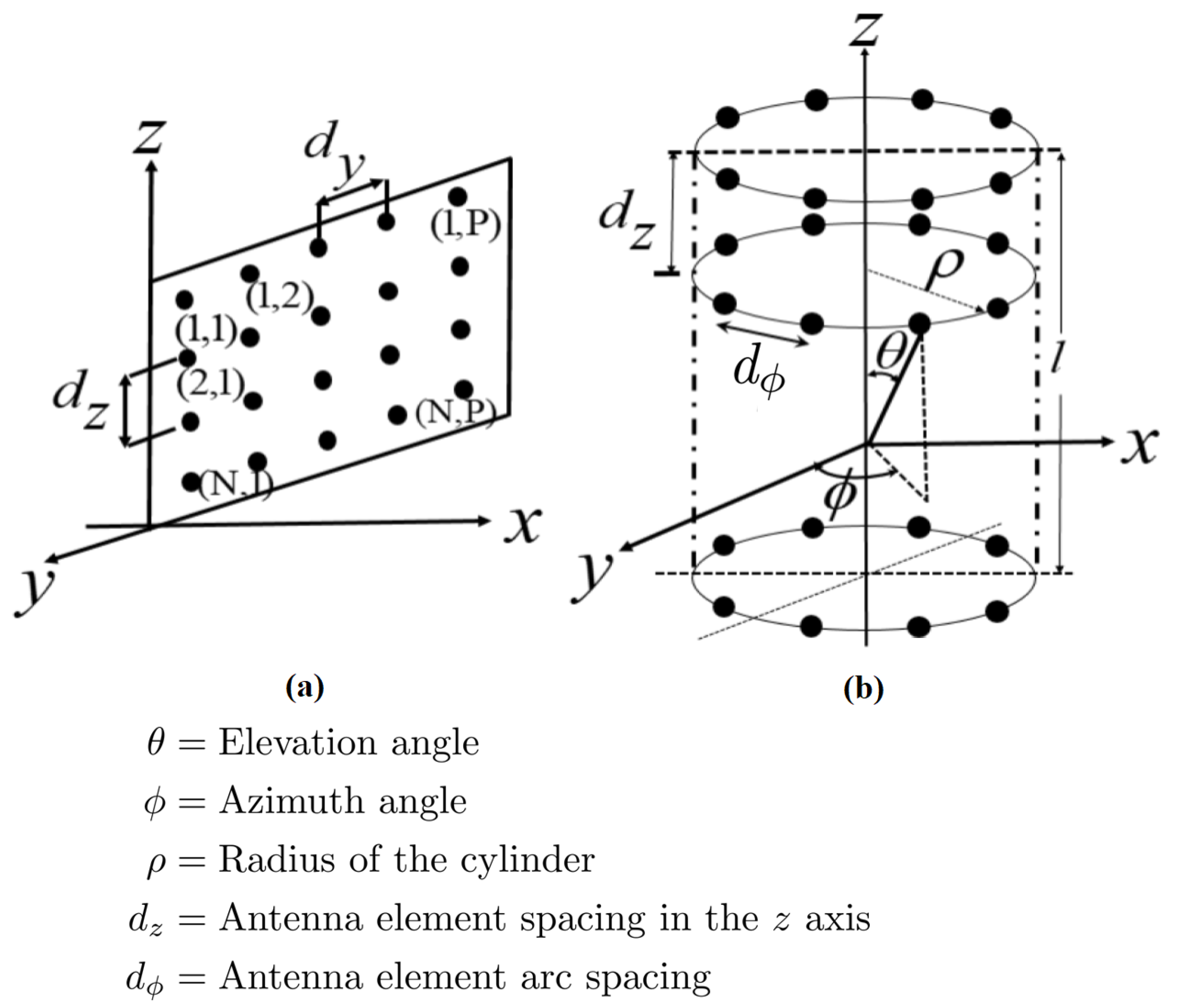
  • We examine a two-stage downlink mMIMO CR-NOMA GBSM system and introduce a new channel model when the transmitter is URA or CA. To reduce the computational complexity of the 3D GBSM channel, we define the antenna elements’ location vector based on the physical dimension of the antenna array. We illustrate the transmitter with a massive antenna system following the models discussed in [17]. Here, the relay and user equipment only has a single antenna.
  • Two coding schemes, AF and DF, are incorporated into the channel model to improve the channel performance.
  • For performance analysis, evaluation and comparison, we present outage probability and achievable rate for the two-stage mMIMO CR-NOMA system.
  • Final findings show that the joint contribution between large antenna transmitters and coding schemes with 3D GBSM CR-NOMA presents possible advantages for future communications systems concerning achievable rate, outage probability and Bit-error rate (BER).
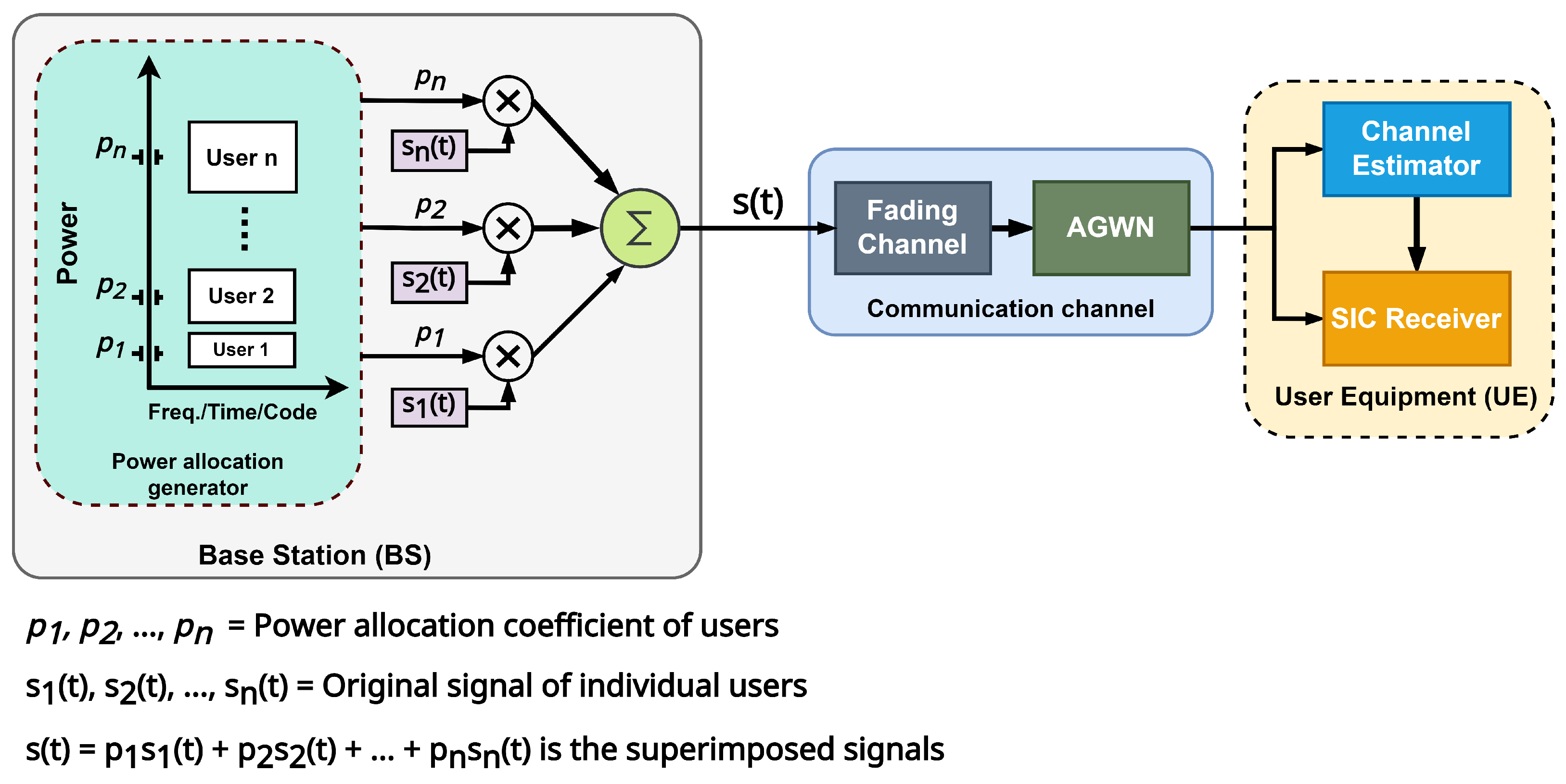
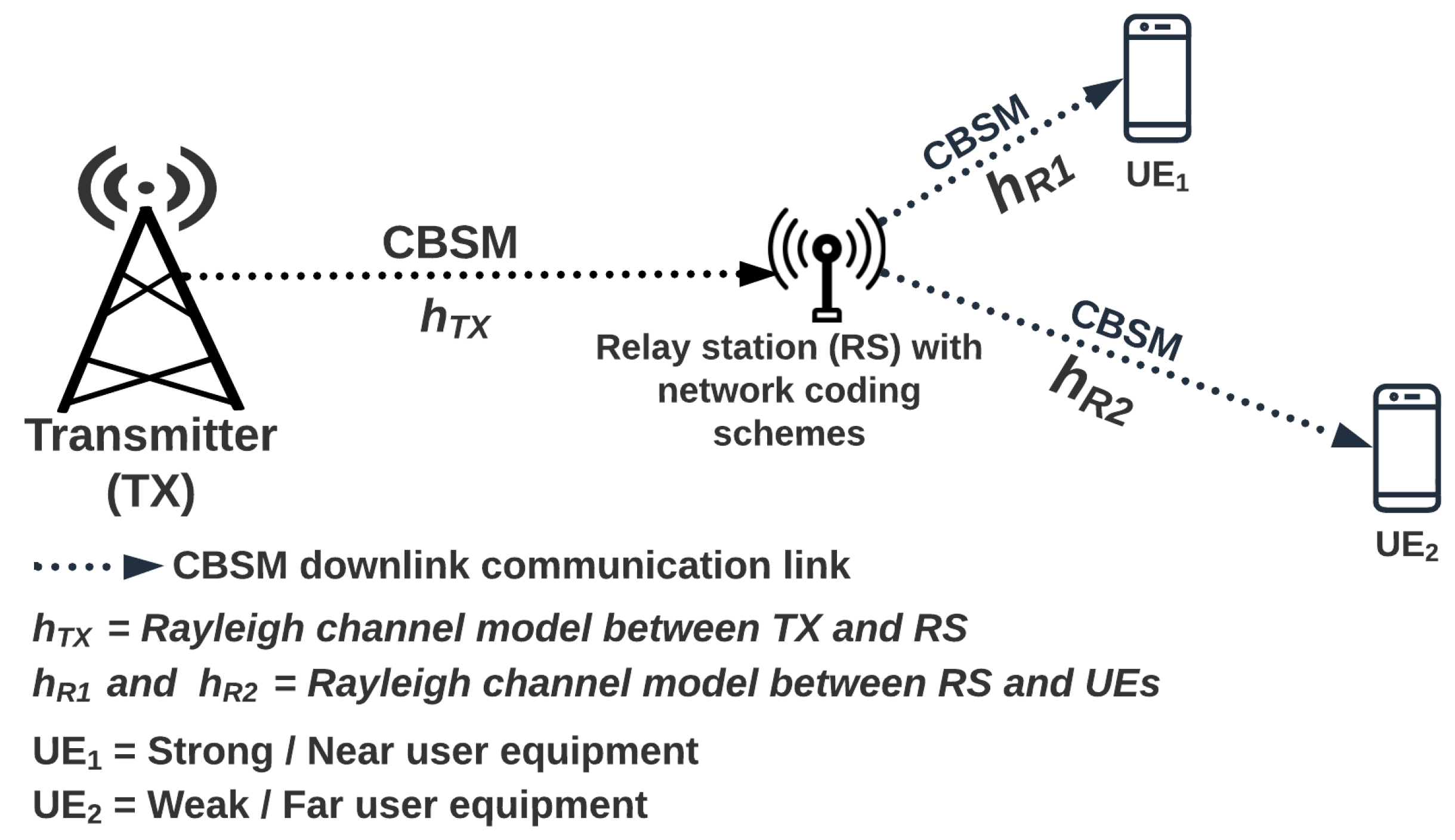
The paper is organized as follows. Section 2 presents the proposed system model for the 3D GBSM URA/CA channels for mMIMO CR-NOMA network. In Section 3 and Section 4 respectively, we present the performance analysis, and simulation and numerical results of the system. We conclude the paper and provide future scope in Section 5.

2. System Model

This section describe a two-stage downlink (DL) communication system, where the transmitter (TX) sends messages to user equipment (UE) through a dedicated relay, as indicated in Figure 3. The TX has a large-scale antenna array (URA or CA) for high spectral-efficient massive access, whereas the UEs and relay station (RS) each have a single antenna. Unlike the CR-NOMA model in Figure 2, where the channel from TX to UEs through RS are theoretical channel models (CBSM), the proposed model replaces the CBSM channel in Figure 2 with GBSM channel model, as shown Figure 3. The strong user equipment (UE1) in the proposed system of Figure 3 is near the RS, whereas the weak user equipment (UE2) is farther away from the RS.
The communication link from TX to UEs through RS is modeled using a 3D GBSM channel model with a single bounce and single cluster. In this context, URA and CA is considered as the transmitters. The proposed system uses two-time slots to achieve a seamless transmission from the TX to UEs through the RS. During the initial time slot, the TX sends signals to the relays using superposition coding. The combined signal ( x ) of the two UEs with superposition coding is given by
x = i = 1 2 α i P s s i
where the ith user transmits power allocation factor, and the source signal is α i and s i , respectively. Noticeably, i = 1 K α i = 1 P s and E x i P s , where K = 2 user equipment and total transmit power is given as P s .
Using NOMA concepts implies that power allocation factors are arranged according to users’ proximity to the RS, that is α 1 < α 2 where α 1 and α 2 are the power allotment coefficient of the strong or near user equipment (UE1) and the weak or far user equipment (UE2) respectively. Hence, without loss of generality, the channel gains of the two UEs are arranged as h R , 1 2 h R , 2 2 . We exploit channel reciprocity through a conventional time division duplex mode [98]. We presume that MIMO downlink (DL) pilots with an N t transmitting antenna allow the TX to estimate the DL channel. Generally, for a single-hop communication involving a transmitter and two users, the received signal (y) by the ith user at the destination with DL data transmission can be expressed as,
y i = H x + n i
where x is an N t × 1 data signal, i = 1 , 2 , H is the communication channel matrix such as the 3D channel realization matrix presented in (12) and (15), n i is the additive Gaussian noise with zero mean and variance, σ 2 .
The following subsection present the 3D GBSM channel models for CA and URA transmitters.

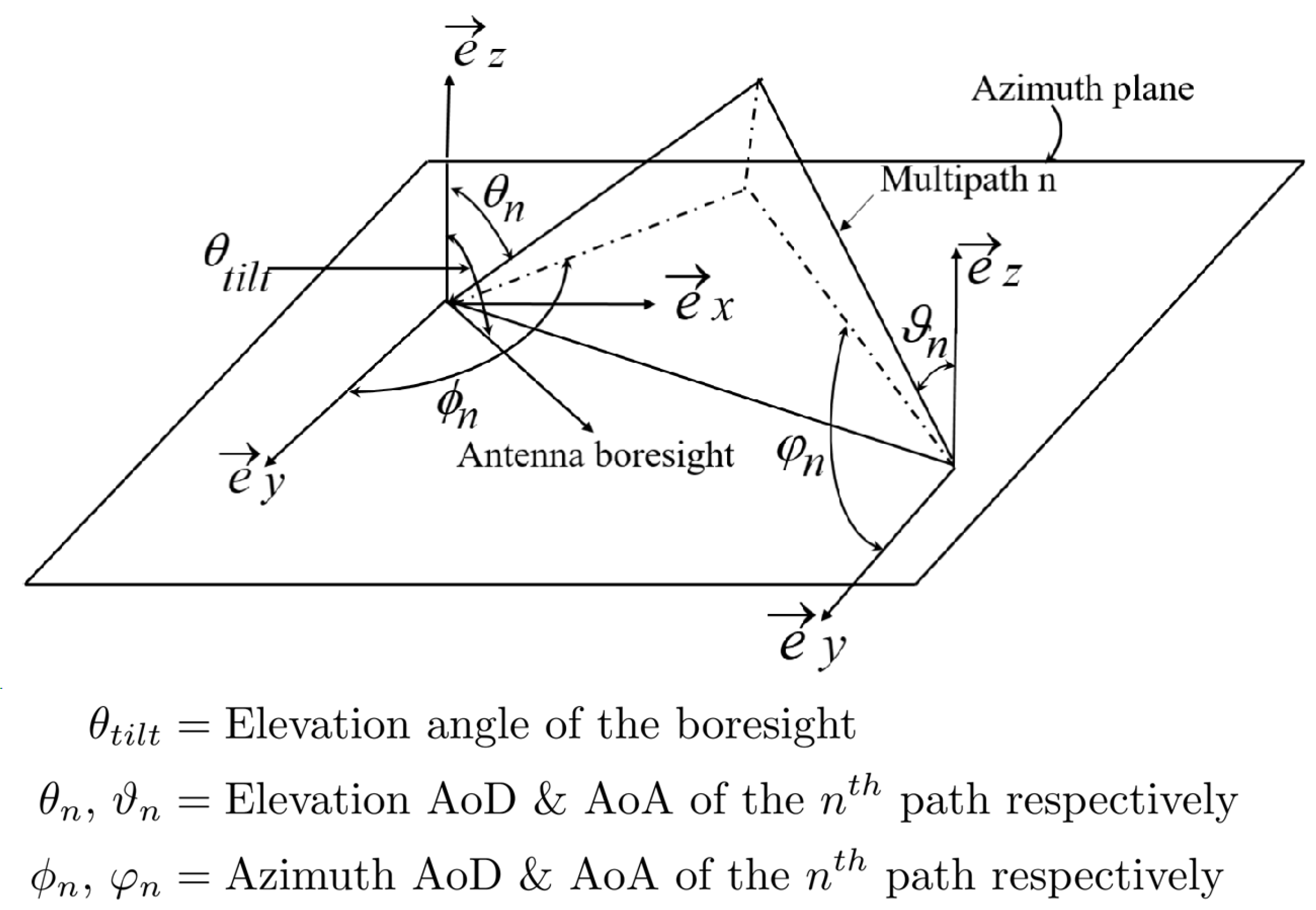
Proposed 3D GBSM Models

We consider the 3GPP’s standard, based on the GBSM method [90,93,99], to provide a new 3D channel model in which the TX antenna is modeled as URA or CA. The main parameters of importance in the 3D channel model are; delay spread (DS), angle of arrival (AoA), azimuth of departure (AoD), elevation angle of arrival (EoA) and departure (EoD) [17,100,101]. In addition, the 3GPP standard under consideration presents the elevation angle of the antenna boresight into the channel and allows for dynamic adaption of the antenna’s downtilt angles θ t i l t . This provides various advantages for 3D beamforming leading to significant improvement in system performance [95]. The 3D channel model is illustrated in Figure 4.
From Figure 4 and the 3GPP’s model, the effective channel between the sth TX antenna port with M subpath and the uth receiver antenna port, as stated in [21,92], is
H s , u 3 D = P n σ S F M n = 1 N κ n G T X 3 D ϕ n A o D , θ n A o D , θ t i l t G R S 3 D φ n A o A , ϑ n A o A × a R X φ n A o A , ϑ n A o A u a T X ϕ n A o D , θ n A o D s
where κ n is the complex random amplitude of the nth path and s = 1 , . . . , N T X , u = 1 , . . . , N R S , ( ϕ n A o D , θ n A o D ) are the azimuth and elevation angles-of-departure (AoD), respectively.
( φ n A o A , ϑ n A o A ) are the azimuth and elevation angles-of-arrival (AoA) of the nth path, respectively. The gain of antenna array at the TX is
G T X 3 D ϕ n A o D , θ n A o D , θ t i l t G T X , H ϕ n A o D G T X , V ( θ n A o D , θ t i l t )
The responses of the antenna array are; ( a R X φ n A o A , ϑ n A o D ) and ( a T X ϕ n A o D , θ n A o D ) .
Following the approach in [90], the precise 3D antenna radiation pattern in both the horizontal ( G T X , H ) and vertical ( G T X , V ) planes is provided by [21],
G T X , H ( ϕ A o D ) = 12 ϕ A o D ϕ 3 d B 2
and
G T X , V ( θ A o D , θ t i l t ) = 12 θ A o D θ t i l t θ 3 d B 2
where ϕ A o D is the horizontal azimuth angle between the user and the array’s boresight, θ A o D is the vertical elevation angle between the user and the array’s boresight, and ϕ 3 d B and θ 3 d B are the horizontal and vertical half-power beamwidths, respectively.
In this study, we consider URA or CA at the TX serving a single antenna RS with half-duplex connection in the model. The path between TX and RS has a single bounce cluster giving us N paths.
For the URA configuration indicated in Figure 5a, the location vector of the antenna element is as follows. As given in [102], the steering vector of the nth propagation path using the URA antenna topology shown in Figure 5a is
a n ( θ n A o D , ϕ n A o D ) = Z sin θ n A o D sin ( β ¯ + ϕ n A o D )
where β ¯ = tan 1 Z z Z z Z y Z y , Z, Z z and Z y can be determined from Figure 5a. The figure shows the scalar z and y axes, where Z is defined [21] as,
Z = Z z 2 + Z y 2
where,
Z z = 2 π d z ( n m ) / λ , Z y = 2 π d y ( p q ) / λ and φ s = c o s 1 ( Z z / Z y )
are obtained. ( m , p ) and ( n , q ) are the coordinates of the elements shown in Figure 5a. The position of the URA antenna element at the TX can be determined by Z β ¯ . d r is the distance between the receiving ports of the RX antennas. The location vector of sth transmit element of the URA is expressed as v t · x s = cos ( ϕ φ s ) sin θ where φ s = 2 π ( n 1 ) / N . The array response of the sth of TX antenna port of URA considering (3) is given by
[ a T X ( ϕ n A o D , θ n A o D ) ] s = exp i k Z cos ( ϕ n A o D φ s ) sin θ n A o D
Similarly, the response of uth UE antenna port with regard to the 3D channel model is
[ a R X ( φ n A o A , ϑ n A o A ) ] u = exp i k ( u 1 ) d r sin φ n A o A sin ϑ n A o A
Thus, the 3D GBSM channel model of the URA transmitter configuration of the proposed mMIMO CR-NOMA model in Figure 3 is
H s , u URA = P n σ S F M n = 1 N κ n G T X 3 D ϕ n A o D , θ n A o D , θ t i l t exp i k Z cos ( ϕ n A o D φ s ) sin θ n A o D × G R S 3 D φ n A o A , ϑ n A o A exp i k ( u 1 ) d r sin φ n A o A sin ϑ n A o A
where P n denotes power of the nth path, σ S F is lognormal shadow fading of the nth path. N is the number of propagation path, M is the number of subpath per path, d r is the separation between the receiving antenna ports, k is the wave number and G R S 3 D is the gain of the RS antenna.
In the case of CA, Figure 5b, considering the array dimension of CA as l = 4 λ with radius given by ρ = 4 λ / l , if d z = 4 λ / M is the wavelength distance in meters between antenna elements on the first and second position in the z direction. Then 4 λ ( m 1 ) / M wavelengths may be used to estimate the placement of the third and following antenna components, where m = 1 , . . . , M is the number of antenna elements on a ring in the z-axis, and λ is the wavelength in meters. The angular position of the nth element of the mth of CA on the x-y plane is expressed as φ s = 2 π ( n 1 ) / N . Consequently, the location vector of the elements is v t · x s = cos ( ϕ φ s ) sin θ . Furthermore, the array response of sth transmit antenna port of the CA is given by
a T X ( ϕ n A o D , θ n A o D ) s = exp i k ρ 4 λ ( m 1 ) M cos ( ϕ n A o D φ s ) sin θ n A o D
Similarly, the response of the uth UE antenna port using the 3D channel model is
a R X ( φ n A o A , ϑ n A o A u = exp i k ( u 1 ) d r sin φ n A o A sin ϑ n A o A
The final 3D GBSM channel model of the proposed model in Figure 3 between a single antenna receiving port uth and a CA transmitter’s transmit antenna port sth is given by [21]
H s , u CA = P n σ S F M n = 1 N κ n G T X 3 D ϕ n A o D , θ n A o D , θ t i l t × exp i k ρ ( 4 λ ( m 1 ) 4 λ ( m 1 ) M M ) cos ( ϕ n A o D φ s ) sin θ n A o D × G R S 3 D φ n A o A , ϑ n A o A exp i k ( u 1 ) d r sin φ n A o A sin ϑ n A o A

3. Achievable Rates, Outage Probabilities and Bit-Error-Rates Analysis

3.1. Transmission between TX and RS

Here, we consider a two-hop downlink communication between a TX and two UEs through a dedicated RS and apply the 3D GBSM channel to the TX−RS and RS−UEs communication links.
We analyze the transmission between TX and RS in the proposed 3D GBSM mMIMO CR-NOMA system model [103,104,105] with large antenna transmitters such as URA or CA in Figure 5, and as illustrated in Figure 3. Two key assumptions are taken into account in the system model. Firstly, there is no direct communication link between TX and UEs. Secondly, users are close to each other in a half-duplex communication mode and have a single antenna each for reception. The communication between TX and UEs takes two stages. During the first stage, the TX transmit a superposition of two distinct signals ( x ) to the relay, from which the relay re-transmits to all UEs. The received signal ( y R S ) at the relay can be expressed as
y R S = α R h T X x + η R
where h T X is the proposed 3D GBSM [103,104,105,106] channel coefficient between the TX and RS, η R is the additive white Gaussian noise (AWGN) with unit variance. α R = d S R δ is the distance-dependent path loss, where d S R is the distance between TX and RS, and δ is the path loss exponent. Again, using the concept of NOMA, users are arranged in ascending order according to the power allocation factors such that α 1 < α 2 , where the superimposed signal ( x ) is given in (1).

3.2. Transmission between RS and UE

3.2.1. Application of AF Coding Scheme

The relay amplifies the incoming signal in the second stage using an AF coding scheme and an amplification factor of (18). Thus, the received signal ( y k AF ) at the k th user (UEk) is
y k AF = y R S h R , k β k G + n k = h R , k β k G α R h T X x + h R , k G β i η R + η k
where n k is the complex additive Gaussian noise at k th user with CN ( 0 , σ 2 ) , h R , k is a 3D channel model following (3) and the β k is path loss between the RS and kth UE. G is the amplifying factor [107] given by
G = α g 2 P s h T X 2 + σ R 2
where α g 2 = ϱ ( 1 d ) k is a non-fading variable path gain, ϱ = 1 is the reference distance’s path-loss exponent, d 0 is the reference distance, d = d e / d 0 is the normalized relay distance from the source, and k is the path-loss exponent of the TX−RS channel. The effective distance d e is the actual distance of TX−RS in meters, where the cell radius is d 0 . To reduce the impact of inter-user interference on each user, SIC at the destination’s receiver [108]. The effective users’ channel gains determine SIC decoding order in ascending order, that is h R , 1 2 h R , 2 2 . The signal-to-interference noise ratio ( γ 1 , 2 AF ) for the strong user (UE1) to decode x 2 by applying SIC processing is given in [109] as
γ 1 , 2 AF = α 2 γ 2 h T X 2 h R , 2 2 γ 2 h T X 2 h R , 1 2 α 1 + γ h T X 2 + h R , 1 2 + 1
After decoding the message of UE2 and subtracting it, UE1 decodes its signal with the following SINR ( γ R , 1 AF ) between the RS and UE1 [109].
γ R , 1 AF = α 1 γ 2 h T X 2 h R , 1 2 γ h T X 2 + h R , 1 2 + 1
The SINR ( γ R , 2 AF ) between the RS and the UE2 to detect its own message is expressed in [109] as
γ R , 2 AF = α 2 γ 2 h T X 2 h R , 2 2 γ 2 h T X 2 h R , 2 2 α 1 + γ h T X 2 + h R , 2 2 + 1
where γ gives the average signal-to-noise ratio (SNR).

3.2.2. Application of DF Coding Scheme

During the first time slot, the TX transmits a superimposed signal according to NOMA principles to the relay. The achievable rates ( R x 1 RS and R x 2 RS ) for the relay to decode x 1 and x 2 are given [109] by
R x 1 RS = B log 2 1 + α 1 γ h T X 2 α 2 γ h T X 2 + 1
and
R x 2 RS = B log 2 1 + α 2 γ h T X 2
where α 1 and α 2 are power allocation factors associated with x 1 and x 2 , respectively. UE1’s signal x 1 and UE2’s signal x 2 are the vector elements of x .
Given that the relay can decode the signal from TX of the two NOMA users, the observable signal ( y k DF ) at UE1 and UE2 in the second slot may be stated as
y k DF = h R , k β k x + η k
where k = UE , β k > 0 denotes the power allocation factor of the kth UE. Here, β 1 + β 2 = 1 . Following the principle of NOMA scheme, the decoding order at the relay is x 1 x 2 . The relay first detects x 1 by treating x 2 as noise. It then subtracts x 1 from the y R S in (16) to identify x 2 . By employing SIC, the SINR ( γ 1 , 2 DF ) at UE1 to detect x 2 is given [109] by
γ 1 , 2 DF = β 2 γ h R , 1 2 β 1 γ h R , 1 2 + 1
The SINR ( γ R , 1 DF ) for UE1 to detect its own signal is
γ R , 1 DF = β 1 γ h R , 1 2
Similarly, the SINR ( γ R , 2 DF ) at UE2 is given [109] by
γ R , 2 DF = β 2 γ h R , 2 2 β 1 γ h R , 2 2 + 1

3.3. Achievable Rates Analysis

The maximum rate in the channel where the BER tends to zero [110] describes the achievable rate of the system. When the CSI is unknown at the transmitter, if separate equi-powered transmissions are assumed, the achievable rates of the UEs can be determined using SINR values. From (19)–(21), the achievable rates of the UEs using AF coding scheme are respectively given by
R UE 1 AF = B l o g 2 ( 1 + γ R , 1 AF ) and R UE 2 AF = B l o g 2 ( 1 + γ R , 2 AF )
For DF coding scheme, the achievable rates at the destination nodes from (25)–(27) are
R UE 1 DF = min [ R x 1 RS , B l o g 2 ( 1 + γ R , 1 DF ) ] and R UE 2 DF = min [ R x 2 RS , B l o g 2 ( 1 + γ R , 2 DF ) ]
The relay transmits the decoded signals to all UES in the second time slot.

3.4. Outage Probabilities Analysis

To determine the likelihood that a data stream may have an outage event where the achievable rate is lower than the encoded data rate [15], we examine the outage probability where the UE1 can detect x 2 and x 1 . Given the previous definition, the outage probability ( P 1 ) of UE1 with the threshold SNRs of CR-NOMA users UE1 and UE2 (denoting Ω 1 , Ω 2 , respectively) may be described in [109] as
P 1 = 1 P r ( ξ RS ξ Ω 2 , ξ RS ξ Ω 1 ) × 1 P r ( ξ l , 2 X ξ Ω 2 , ξ 1 X ξ Ω 1 )
where ξ Ω 1 = 2 2 R 1 ˜ 1 and ξ Ω 2 = 2 2 R 2 ˜ 1 are the decoding threshold with R 1 ˜ and R 2 ˜ being the target rate of UE1 and UE2, respectively. ξ RS is the SINR between TX and RS, ξ RS is the decoding threshold of the direct transmission to the RS. ξ 1 X and ξ 2 X are the SINR defined at (20), (21), (26) and (27), where X in the equation denotes AF or DF coding scheme. Similarly, the outage probability ( P 2 ) of UE2 is
P 2 = P r ( ξ RS < ξ Ω 2 , ξ 2 X < ξ Ω 2 )

3.5. Bit-Error-Rates (BER) Analysis

We give the Bit-error analysis for the proposed CR-NOMA system in accordance with the guidelines in [111,112]. The average error probability ( P e UE 1 ) of the UE1 when its symbols are identified properly and erroneously via SIC processing is shown in [111] as
P e UE 1 = 1 2 1 γ B 1 2 + γ B 1 + 1 8 γ B 2 2 + γ B 2 γ B 3 2 + γ B 3 + γ B 4 2 + γ B 4 γ B 5 2 + γ B 5
where ε 1 and ε 2 are the UE1 and UE2 signal energies, respectively. The SNRs of different constellation points of x 1 and x 2 are given by
γ B 1 = ε 1 N 0 E h R , 1 2 γ B 2 = 2 ε 2 + ε 1 2 N 0 E h R , 1 2 γ B 3 = 2 ε 2 ε 1 2 N 0 E h R , 1 2
and
γ B 4 = 2 2 ε 2 + ε 1 2 N 0 E h R , 1 2 γ B 5 = 2 2 ε 2 ε 1 2 N 0 E h R , 1 2
Equation (33) represents the condition that UE1 is able to detect its signals correctly, whereas (34) represents the condition that the signals are incorrectly detected.
Similarly, the total average BER ( P e UE 2 ) performance of UE2 from [111] is
P e UE 2 = 1 4 1 γ A 1 2 + γ A 1 + 1 γ A 2 2 + γ A 2
where γ A 1 and γ A 2 are the SNRs of different signal constellation points expressed as
γ A 1 = 2 ε 2 + ε 1 2 N 0 E h R , 2 2 γ A 2 = 2 ε 2 ε 1 2 N 0 E h R , 2 2

4. Numerical Results and Analyses

In this section, we validate the proposed 3D channel model for an mMIMO CR-NOMA system through simulation using the MatLab numeric computing platform for evaluation purposes. We compared the results to a system using CBSM channel model such as Rayleigh fading channel [17,19]. The major application of CBSM is for assessing theoretical performance because it is imprecise at simulating channel characteristics for real large MIMO systems.
We evaluate the proposed 3D GBSM models by setting the AoA cluster ( ϕ , θ ) to 0.7, and AoA offset standard deviations, ( σ Δ ϕ , σ Δ θ ) to 0.3 at 2.6 GHz carrier frequency [113]. The proposed system model uses 5G network operating bandwidth of 200 MHz [114]. We consider the entire physical space of URA antenna components at the TX as l = 4 λ on both the y and z axes.
Similarly, for the CA, adjacent antenna element are spaced by l = 4 λ on the z axis and are located at a maximum radius of ρ = 2 π / l from the cylinder center to x , y plane. The CA has a 2 × N t number of components, and in the azimuth domain, there are two circular arrays with N t = 4 elements each. We studied a N t × N t array element in the case of the URA, where N t is the number of antenna elements in a row or column.
For each TX antenna topology, we calculated the channel coefficient as the distance between the sth transmit antenna port and the uth receive antenna port. In order to validate the proposed model, we considered θ t i l t = 95 ° , θ 3 d B = 15 ° and ϕ 3 d B = 70 ° at the TX for the 3D channel modeling between the TX, RS and UEs in Figure 3. Table 2 gives the summary of simulation parameters.
Additionally, the power of azimuth spectrum (PAS) arriving at the RS, multipath components for each AoA, and the multipath delay associated with AoD are all represented as Laplacian distributions with specified 3GPP specifications. For the cooperative communication at the relay, we considered DF and AF with the proposed 3D GBSM between the TX, RS and UEs. The OP, achievable rate and BER are determined for each relaying scheme and compared with the results of a system using CBSM, as illustrated in Figure 2.

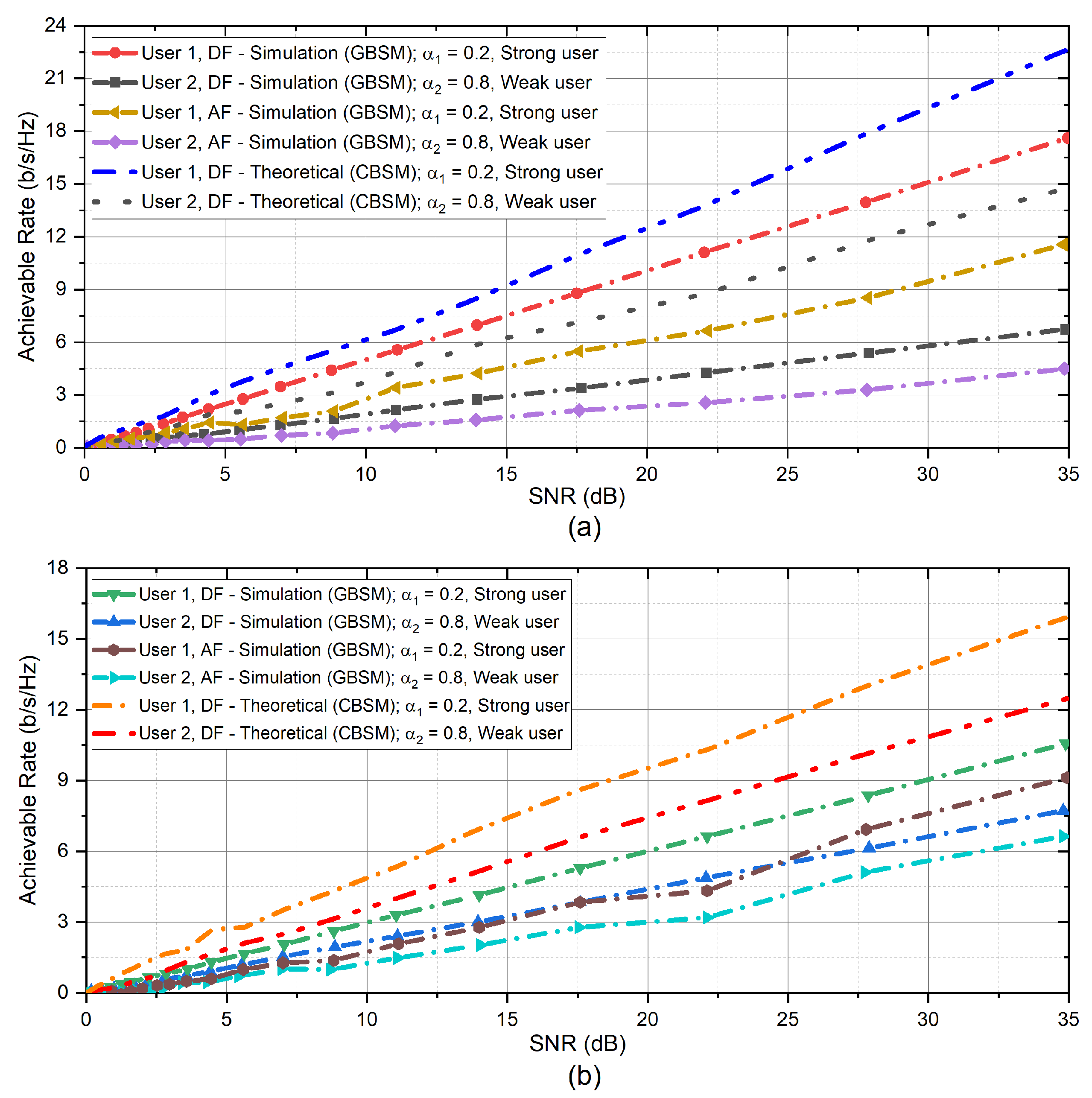
4.1. Achievable Rate Performance

For achievable rate analysis, (28) and (29) were used to determine the achievable rates of AF and DF. In Figure 6, the UE1 achievable rate obtained using DF coding scheme is higher than that of the AF coding scheme across the entire SNR, irrespective of the TX type used in the proposed 3D GBSM channel model. It can also be seen from the comparison of the results of DF and AF for CA channel model that the capacities of UE1 and UE2 have similarities with higher capacity values of AF coding scheme at higher SNR values.

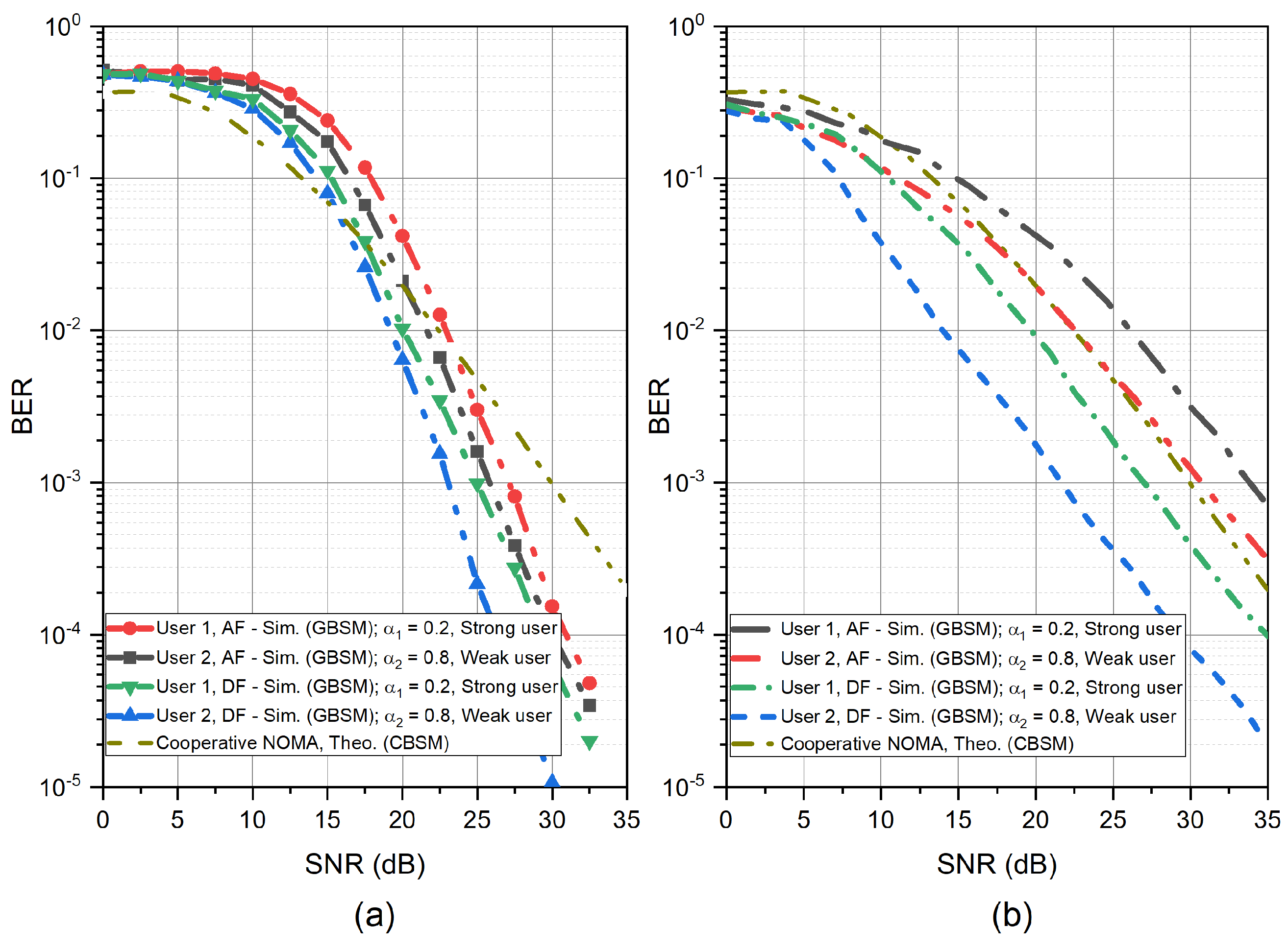
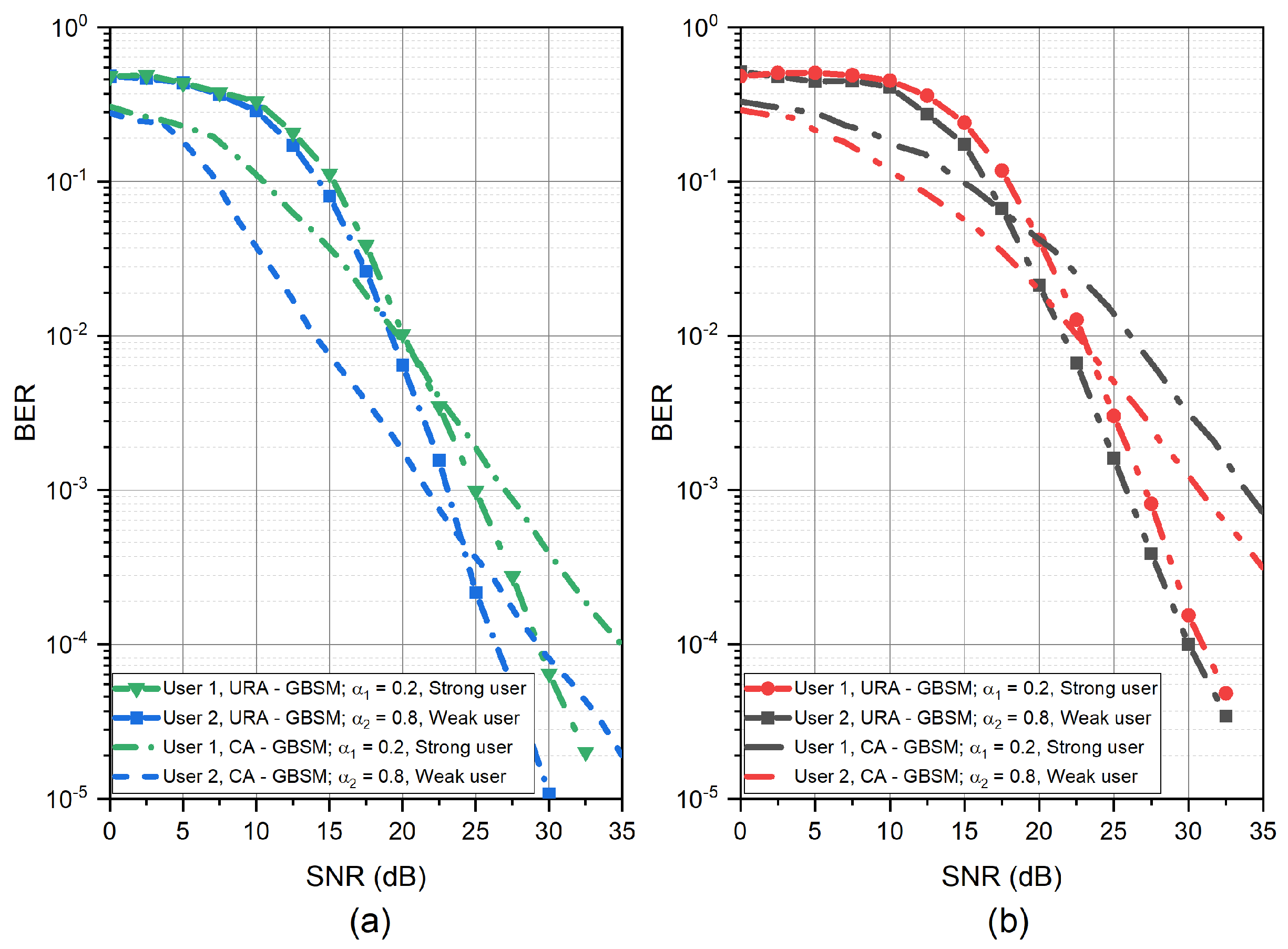
4.2. BER Performance

For BER performance evaluation, we use (12) and (15) that are based on the channel coefficients between the TX, RS and UEs. The transmissions between TX and UEs through were further examined using (20) and (21). The BER of UE1 and UE2 was estimated using (32) and (35), respectively. Figure 7 and Figure 8 show the BER for various SNR values in dB for AF and DF coding schemes. The number of TX antenna elements in the proposed 3D GBSM channel model is sixty-eight (68) for both URA and CA. The performance of the 3D model using CA at the transmitter achieves better at low SNR values as compared with the URA in Figure 7 and Figure 8. In both cases of Figure 7 and Figure 8, the performance of UE1 is better than UE2. This is because the received power at UE1 is higher than that of UE2 since it is closer to the RS.
The Table 3 lists the BER performance of the CR-NOMA system with the proposed GBSM channel with URA antenna array configuration at the TX using AF or DF coding schemes at the RS. The BER of the DF coding scheme at 20 dB shows performance similar to prior work that uses the theoretical channel model (CBSM channel model). On the other hand, the AF coding scheme’s BER performance of the proposed model performed worse than CBSM with AF coding scheme.
The reason is due to the high unpredictability of the GBSM parameters and high computational complexity, which causes a significant amount of noise signal in the channel and at the RS.

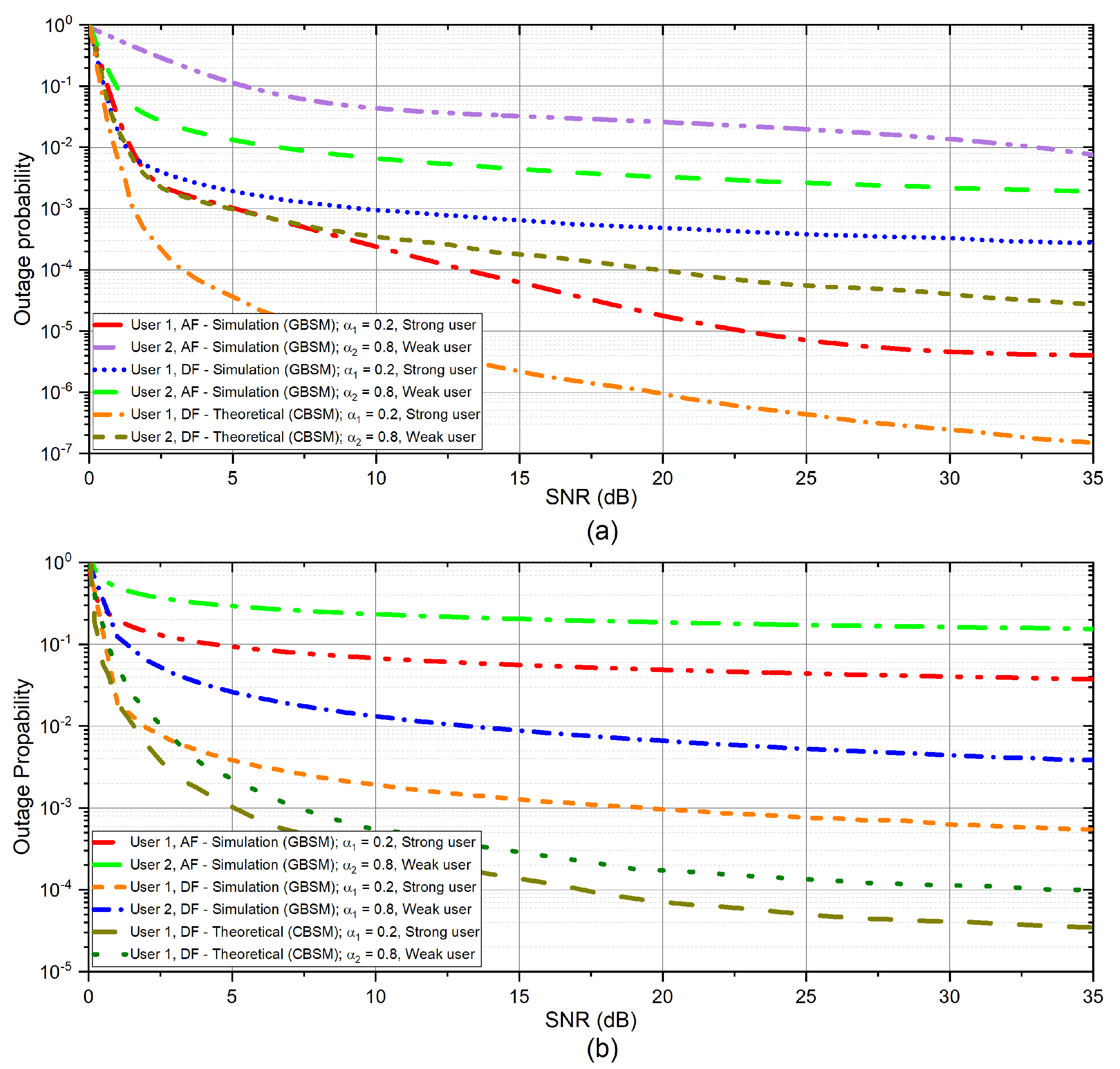
4.3. Outage Probability (OP) Performance

The analysis cannot be complete without examining the outage probability. Employing 3D GBSM URA and CA channel models in (12) and (15), we demonstrate the outage probability of mMIMO CR-NOMA as a function of transmitting SNR in Figure 9. The performance disparity between the two users, UE1 and UE2, spreads across the whole range of SNR. This is demonstrated in the OP outcome of the 3D URA system. It is important to note that modifying the transmitter array arrangement and expanding the TX’s antenna elements while keeping a single antenna at the relay node can dramatically increase system outage performance.
Furthermore, it demonstrates that UE2’s outage performance is poorer than UE1. This means that using less transmit power at the relays lowers the hop’s outage performance, which in turn affects the total outage performance. This is because signal x 1 , which is regarded as noise, causes interference in the communication link between the RS and UE2. UE1 signal x 1 is amplified when the UE2’s signal ( x 2 ) is amplified by RS with AF coding scheme. The interference impacts the decoding performance of the RS when using the AF coding scheme for the connection between RS−UE2. Again, Figure 9 shows outage probabilities of two users with AF and DF relay coding schemes. It can be seen that under the 3D URA channel model, the OP of the DF coding scheme achieves higher performances than the AF coding scheme.
We further perform analysis using the CA channel model. Here, the OP of UE1 using AF coding scheme performs better than that of the DF coding scheme, unlike that of the OP of the URA channel model. Generally, the performance of the system using the CA is better than URA for both AF and DF coding schemes. In Table 4, we compare OP performance at SNR of 15 dB of the proposed 3D GBSM channel models with prior works that use CBSM models.

5. Conclusions and Future Scope

In this paper, different from previous works on mMIMO CR-NOMA system, we have presented a 3D GBSM channel model between TX−RS and RS−UEs communication links. We examined a two-stage downlink mMIMO CR-NOMA system with the 3D GBSM channel model where the transmitter is represented by CA or URA. We have undertaken performance analyses of the proposed system model with simulations and compared it with the theoretical results of systems using CBSM. Generation of 3D GBSM channel model is complex, therefore, to minimize the computational complexity of the channel, we defined the antenna location vector based on the physical dimension of the antenna configuration. The proposed 3D GBSM channel model incorporates various network coding schemes such as DF and AF for better channel and system performance. For performance analysis, we derived the probability of an outage, the achievable rate and the bit-error rate for the two-stage system. According to the results, the combination of CA and AF gives a better outage probability. Finally, even though the proposed 3D GBSM channel model has a higher computational cost in terms of complexity, the results reveal that the performance difference between the theoretical channel model (CBSM) and GBSM is minimal. The work can further be extended to cover millimeter-wave CR-NOMA with multiple antenna at the TX, RS and UEs. Again, the effect of spatial correlation of antenna array configuration on the performance of 3D GBSM in CR-NOMA systems presents good future research opportunities.

Author Contributions

Conceptualization, S.T.-K. and E.A.A.; methodology, S.T.-K.; software, S.T.-K. and E.A.A.; validation, S.T.-K., E.A.A., K.A.-P.A. and S.A.A.; formal analysis, S.T.-K.; resources, E.A.A., S.A.A. and M.O.A.; writing—original draft preparation, S.T.-K., E.A.A. and K.A.-P.A.; writing—review and editing, S.T.-K., E.A.A., K.A.-P.A., S.A.A. and M.O.A.; supervision, E.A.A., S.A.A. and M.O.A. All authors have read and agreed to the published version of the manuscript.

Funding

This research was supported by the University of Zululand and Telkom SA LTD.

Data Availability Statement

Not applicable.

Acknowledgments

The authors are grateful to the University of Zululand and Telkom SA LTD, South Africa, and the Center for RFIC and System Technology, School of Communication and Information Engineering, University of Electronic Science and Technology of China for their contribution.

Conflicts of Interest

The authors declare no conflict of interest.

Abbreviations

The following abbreviations are used in this manuscript:
NOMANon-Orthogonal Multiple Access
5GFifth Generation
SICSuccessive Interference Cancellation
CR-NOMA        Cooperative Relay Non-Orthogonal Multiple Access
mMIMOMassive Multiple-Input Multiple-Output
CBSMCorrelated-Based Stochastic Channel Model
GBSMGeometric-Based Stochastic Channel Model
3GPPThird Generation Partnership Project
3DThree Dimension
URAUniform Rectangular Array
CACylindrical
Array
OPOutage Probability
AFAmplify-and-Forward
DFDecode-and-Forward
OMAOrthogonal
Multiple Access
MIMOMultiple-Input Multiple-Output
CSIChannel State Information
CFCompress-and-Forward
CpFCompute-and-Forward
BERBit-Error-Rate
EHEnergy Harvesting
BSBase
Station
SNRSignal-to-Noise Ratio
TXTransmitter
UEUser Equipment
RSRelay Station
P s Total Transmit Power
DLDownlink
DSDelay Spread
AoAAngle of Arrival
AoDAzimuth of Departure
EoDElevation Angle of Departure
EoAElevation Angle of Arrival
AWGNAdditive White Gaussian Noise
d S R Distance between TX and Rs
SINRSignal-to-Interference Noise Ratio
PASPower of Azimuth Spectrum

References

  1. Penttinen, J.T. 5G Explained: Security and Deployment of Advanced Mobile Communications; John Wiley & Sons: Hoboken, NJ, USA, 2019. [Google Scholar]
  2. Shahraki, A.; Abbasi, M.; Piran, M.; Chen, M.; Cui, S. A comprehensive survey on 6g networks: Applications, core services, enabling technologies, and future challenges. arXiv 2021, arXiv:2101.12475. [Google Scholar]
  3. Osseiran, A.; Parkvall, S.; Persson, P.; Zaido, A.; Magnusson, S.; Balachandran, K. 5G Wireless Access Network; Whitepaper; Ericsson: Stockholm, Sweden, 2020. [Google Scholar]
  4. Carugi, M. Key features and requirements of 5G/IMT-2020 networks. In Proceedings of the ITU Arab Forum on Emerging Technologies, Algiers, Algeria, 14–15 February 2018. [Google Scholar]
  5. Yuan, M.; Song, D.; Li, B. A Comparative Study on Key Technologies of Ultra-Reliable Low Latency Communication. In Proceedings of the International Conference on Machine Learning for Cyber Security, Guangzhou, China, 8–10 October 2020; Springer: Berlin/Heidelberg, Germany, 2020; pp. 112–124. [Google Scholar]
  6. Carcel, J.L.; Mouhouche, B.; Fuentes, M.; Garro, E.; Gomez-Barquero, D. IMT-2020 key performance indicators: Evaluation and extension towards 5G new radio point-to-multipoint. In Proceedings of the 2019 IEEE International Symposium on Broadband Multimedia Systems and Broadcasting (BMSB), Jeju, Korea, 5–7 June 2019; pp. 1–5. [Google Scholar]
  7. Akbar, A.; Jangsher, S.; Bhatti, F.A. NOMA and 5G emerging technologies: A survey on issues and solution techniques. Comput. Netw. 2021, 190, 107950. [Google Scholar] [CrossRef]
  8. Basnayake, V.; Jayakody, D.N.K.; Sharma, V.; Sharma, N.; Muthuchidambaranathan, P.; Mabed, H. A New Green Prospective of Non-orthogonal Multiple Access (NOMA) for 5G. Information 2020, 11, 89. [Google Scholar] [CrossRef] [Green Version]
  9. Ghanami, F.; Hodtani, G.A.; Vucetic, B.; Shirvanimoghaddam, M. Performance analysis and optimization of NOMA with HARQ for short packet communications in massive IoT. IEEE Internet Things J. 2020, 8, 4736–4748. [Google Scholar] [CrossRef]
  10. Budhiraja, I.; Kumar, N.; Tyagi, S.; Tanwar, S.; Han, Z.; Suh, D.Y.; Piran, M.J. A Systematic Review on NOMA Variants for 5G and Beyond. IEEE Access 2021, 9, 85573–85644. [Google Scholar] [CrossRef]
  11. Islam, S.R.; Zeng, M.; Dobre, O.A.; Kwak, K.S. Nonorthogonal multiple access (NOMA): How it meets 5G and beyond. arXiv 2019, arXiv:1907.10001. [Google Scholar]
  12. Proakis, J.G.; Salehi, M.; Zhou, N.; Li, X. Communication Systems Engineering; Prentice Hall New Jersey: Upper Saddle River, NJ, USA, 1994; Volume 2, Chapter 1; pp. 20–21. [Google Scholar]
  13. Reddy, B.S.K.; Mannem, K.; Jamal, K. Software Defined Radio Based Non-orthogonal Multiple Access (NOMA) Systems. Wirel. Pers. Commun. 2021, 119, 1251–1273. [Google Scholar] [CrossRef]
  14. Islam, S.; Zeng, M.; Dobre, O.A. NOMA in 5G systems: Exciting possibilities for enhancing spectral efficiency. arXiv 2017, arXiv:1706.08215. [Google Scholar]
  15. Ntiamoah-Sarpong, K.; Huang, Z.; Wen, G.; Ampoma, A.E. Performance of non-orthogonal multiple access: Analysis using compute-and-forward cooperative relaying in 5G networks. IET Commun. 2020, 14, 3058–3064. [Google Scholar] [CrossRef]
  16. Laneman, J.N.; Tse, D.N.; Wornell, G.W. Cooperative diversity in wireless networks: Efficient protocols and outage behavior. IEEE Trans. Inf. Theory 2004, 50, 3062–3080. [Google Scholar] [CrossRef]
  17. Zheng, K.; Ou, S.; Yin, X. Massive MIMO channel models: A survey. Int. J. Antennas Propag. 2014, 2014, 848071. [Google Scholar] [CrossRef] [Green Version]
  18. Liu, Y.; Wang, C.X.; Lopez, C.F.; Goussetis, G.; Yang, Y.; Karagiannidis, G.K. 3D non-stationary wideband tunnel channel models for 5G high-speed train wireless communications. IEEE Trans. Intell. Transp. Syst. 2019, 21, 259–272. [Google Scholar] [CrossRef]
  19. Zhang, P.; Chen, J.; Yang, X.; Ma, N.; Zhang, Z. Recent research on massive MIMO propagation channels: A survey. IEEE Commun. Mag. 2018, 56, 22–29. [Google Scholar] [CrossRef]
  20. Zheng, K.; Zhao, L.; Mei, J.; Shao, B.; Xiang, W.; Hanzo, L. Survey of large-scale MIMO systems. IEEE Commun. Surv. Tutor. 2015, 17, 1738–1760. [Google Scholar] [CrossRef] [Green Version]
  21. Ampoma, A.E.; Wen, G.; Huang, Y.; Gyasi, K.O.; Tebe, P.I.; Ntiamoah-Sarpong, K. Spatial correlation models of large-scale antenna topologies using maximum power of offset distribution and its application. IEEE Access 2018, 6, 36295–36304. [Google Scholar] [CrossRef]
  22. He, D.; Ai, B.; Guan, K.; Wang, L.; Zhong, Z.; Kürner, T. The design and applications of high-performance ray-tracing simulation platform for 5G and beyond wireless communications: A tutorial. IEEE Commun. Surv. Tutor. 2018, 21, 10–27. [Google Scholar] [CrossRef]
  23. Zaghdoud, N.; Alouane, W.H.; Boujemaa, H.; Touati, F. Secure performance of AF and DF relaying in cooperative NOMA systems. In Proceedings of the 2019 19th International Conference on Sciences and Techniques of Automatic Control and Computer Engineering (STA), Sousse, Tunisia, 24–26 March 2019; pp. 614–619. [Google Scholar]
  24. Gong, X.; Yue, X.; Liu, F. Performance analysis of cooperative NOMA networks with imperfect CSI over Nakagami-m fading channels. Sensors 2020, 20, 424. [Google Scholar] [CrossRef] [Green Version]
  25. Tran, D.D.; Ha, D.B.; So-In, C.; Tran, H.; Nguyen, T.G.; Baig, Z.A.; Sanguanpong, S. Performance Analysis of DF/AF Cooperative MISO Wireless Sensor Networks With NOMA and SWIPT Over Nakagami-m Fading. IEEE Access 2018, 6, 56142–56161. [Google Scholar] [CrossRef]
  26. Aldababsa, M.; Kucur, O. Performance of cooperative multiple-input multiple-output NOMA in Nakagami-m fading channels with channel estimation errors. IET Commun. 2020, 14, 274–281. [Google Scholar] [CrossRef]
  27. Nguyen, X.X.; Do, D.T. System performance of cooperative NOMA with full-duplex relay over Nakagami-m fading channels. Mob. Inf. Syst. 2019, 2019, 7547431. [Google Scholar]
  28. Li, G.; Mishra, D. Cooperative NOMA networks: User cooperation or relay cooperation? In Proceedings of the ICC 2020—2020 IEEE International Conference on Communications (ICC), Dublin, Ireland, 7–11 June 2020; pp. 1–6. [Google Scholar]
  29. Goutham, V.; Harigovindan, V. Full-duplex cooperative relaying with NOMA for the performance enhancement of underwater acoustic sensor networks. Eng. Sci. Technol. Int. J. 2021, 24, 1396–1407. [Google Scholar] [CrossRef]
  30. Kramer, G.; Maric, I.; Yates, R.D. Cooperative Communications; Now Publishers Inc.: Hanover, MA, USA, 2007. [Google Scholar]
  31. Zhou, Y.; Wong, V.W.; Schober, R. Performance analysis of cooperative NOMA with dynamic decode-and-forward relaying. In Proceedings of the GLOBECOM 2017—2017 IEEE Global Communications Conference, Singapore, 4–8 December 2017; pp. 1–6. [Google Scholar]
  32. Umakoglu, I.; Namdar, M.; Basgumus, A.; Kara, F.; Kaya, H.; Yanikomeroglu, H. BER Performance Comparison of AF and DF Assisted Relay Selection Schemes in Cooperative NOMA Systems. In Proceedings of the 2021 IEEE International Black Sea Conference on Communications and Networking (BlackSeaCom), Bucharest, Romania, 24–28 May 2021; pp. 1–6. [Google Scholar]
  33. Zheng, B.; Wen, M.; Wang, C.X.; Wang, X.; Chen, F.; Tang, J.; Ji, F. Secure NOMA based two-way relay networks using artificial noise and full duplex. IEEE J. Sel. Areas Commun. 2018, 36, 1426–1440. [Google Scholar] [CrossRef]
  34. Men, J.; Ge, J. Performance analysis of non-orthogonal multiple access in downlink cooperative network. IET Commun. 2015, 9, 2267–2273. [Google Scholar] [CrossRef]
  35. Abbasi, O.; Ebrahimi, A. Cooperative NOMA with full-duplex amplify-and-forward relaying. Trans. Emerg. Telecommun. Technol. 2018, 29, e3421. [Google Scholar] [CrossRef]
  36. Liang, X.; Wu, Y.; Ng, D.W.K.; Zuo, Y.; Jin, S.; Zhu, H. Outage performance for cooperative NOMA transmission with an AF relay. IEEE Commun. Lett. 2017, 21, 2428–2431. [Google Scholar] [CrossRef] [Green Version]
  37. Li, Y.; Kishore, S. Asymptotic analysis of amplify-and-forward relaying in Nakagami-fading environments. IEEE Trans. Wirel. Commun. 2007, 6, 4256–4262. [Google Scholar] [CrossRef]
  38. Peppas, K.P.; Alexandropoulos, G.C.; Mathiopoulos, P.T. Performance Analysis of Dual-Hop AF Relaying Systems over Mixed ημ and κμ Fading Channels. IEEE Trans. Veh. Technol. 2013, 62, 3149–3163. [Google Scholar] [CrossRef]
  39. Kim, J.B.; Lee, I.H. Capacity analysis of cooperative relaying systems using non-orthogonal multiple access. IEEE Commun. Lett. 2015, 19, 1949–1952. [Google Scholar] [CrossRef]
  40. So, J.; Sung, Y. Improving non-orthogonal multiple access by forming relaying broadcast channels. IEEE Commun. Lett. 2016, 20, 1816–1819. [Google Scholar] [CrossRef]
  41. Liu, H.; Ding, Z.; Kim, K.J.; Kwak, K.S.; Poor, H.V. Decode-and-forward relaying for cooperative NOMA systems with direct links. IEEE Trans. Wirel. Commun. 2018, 17, 8077–8093. [Google Scholar] [CrossRef] [Green Version]
  42. Li, G.; Mishra, D.; Hu, Y.; Huang, Y.; Jiang, H. Adaptive Relay Selection Strategies for Cooperative NOMA Networks With User and Relay Cooperation. IEEE Trans. Veh. Technol. 2020, 69, 11728–11742. [Google Scholar] [CrossRef]
  43. Wu, X.; Xie, L.L. On the optimal compressions in the compress-and-forward relay schemes. IEEE Trans. Inf. Theory 2013, 59, 2613–2628. [Google Scholar] [CrossRef] [Green Version]
  44. Liaqat, M.; Noordin, K.A.; Latef, T.A.; Dimyati, K. Power-domain non orthogonal multiple access (PD-NOMA) in cooperative networks: An overview. Wirel. Netw. 2020, 26, 181–203. [Google Scholar] [CrossRef]
  45. Zeng, M.; Hao, W.; Dobre, O.A.; Ding, Z. Cooperative NOMA: State of the Art, Key Techniques, and Open Challenges. IEEE Netw. 2020, 34, 205–211. [Google Scholar] [CrossRef]
  46. Li, Y.; Li, Y.; Chu, X.; Ye, Y.; Zhang, H. Performance analysis of relay selection in cooperative NOMA networks. IEEE Commun. Lett. 2019, 23, 760–763. [Google Scholar] [CrossRef]
  47. Kaur, J.; Singh, M.L. User assisted cooperative relaying in beamspace massive MIMO NOMA based systems for millimeter wave communications. China Commun. 2019, 16, 103–113. [Google Scholar] [CrossRef]
  48. Sushma, J.; Gayathri, M.N.; Srivani, S.; Nayak, V.N.; Gurrala, K.K. Performance Analysis and Power allocation for Multi Relay Wireless Cooperative NOMA Networks with Diversity Combining strategies. In Proceedings of the 2020 IEEE International Students’ Conference on Electrical, Electronics and Computer Science (SCEECS), Bhopal, India, 22–23 February 2020; pp. 1–6. [Google Scholar]
  49. Mohammadi, M.; Shi, X.; Chalise, B.K.; Ding, Z.; Suraweera, H.A.; Zhong, C.; Thompson, J.S. Full-duplex non-orthogonal multiple access for next generation wireless systems. IEEE Commun. Mag. 2019, 57, 110–116. [Google Scholar] [CrossRef] [Green Version]
  50. Zhang, Z.; Si, Z. Performance Evaluation and Optimization of Cooperative NOMA over Rayleigh Fading Channels. In Proceedings of the 2020 IEEE International Conference on Communications Workshops (ICC Workshops), Dublin, Ireland, 7–11 June 2020; pp. 1–6. [Google Scholar]
  51. Wang, H.; Shi, R.; Tang, K.; Dong, J.; Liao, S. Performance Analysis and Optimization of a Cooperative Transmission Protocol in NOMA-Assisted Cognitive Radio Networks with Discrete Energy Harvesting. Entropy 2021, 23, 785. [Google Scholar] [CrossRef]
  52. Alnwaimi, G.; Boujemaa, H.; Arshad, K. Throughput optimization of cooperative non orthogonal multiple access. Telecommun. Syst. 2021, 76, 359–370. [Google Scholar] [CrossRef]
  53. Ali, Z.; Khan, W.U.; Ihsan, A.; Waqar, O.; Sidhu, G.A.S.; Kumar, N. Optimizing Resource Allocation for 6G NOMA-enabled Cooperative Vehicular Networks. IEEE Open J. Intell. Transp. Syst. 2021, 2, 269–281. [Google Scholar] [CrossRef]
  54. Reshma, K.; Babu, A. Cooperative NOMA system with incremental relaying and energy harvesting: Performance analysis and optimization. Trans. Emerg. Telecommun. Technol. 2020, 31, e4075. [Google Scholar] [CrossRef]
  55. Nazari, A.; Javan, M.R.; Hosseini, S.S. Resource allocation in power domain NOMA-based cooperative multicell networks. IET Commun. 2020, 14, 1162–1168. [Google Scholar] [CrossRef]
  56. Li, J.; Lei, X.; Diamantoulakis, P.D.; Zhou, F.; Sarigiannidis, P.; Karagiannidis, G.K. Resource allocation in buffer-aided cooperative non-orthogonal multiple access systems. IEEE Trans. Commun. 2020, 68, 7429–7445. [Google Scholar] [CrossRef]
  57. Wang, L.; Xu, D. Resource allocation in downlink SWIPT-based cooperative NOMA systems. KSII Trans. Internet Inf. Syst. (TIIS) 2020, 14, 20–39. [Google Scholar]
  58. Chen, X.; Wen, M.; Mao, T.; Dang, S. Spectrum resource allocation based on cooperative NOMA with index modulation. IEEE Trans. Cogn. Commun. Netw. 2020, 6, 946–958. [Google Scholar] [CrossRef]
  59. Rezaei, A.; Azmi, P.; Yamchi, N.M.; Javan, M.R.; Yanikomeroglu, H. Robust Resource Allocation for Cooperative MISO-NOMA-Based Heterogeneous Networks. IEEE Trans. Commun. 2021, 69, 3864–3878. [Google Scholar] [CrossRef]
  60. Amer, A.; Ahmad, A.M.; Hoteit, S. Resource allocation for downlink full-duplex cooperative NOMA-based cellular system with imperfect SI cancellation and underlaying D2D communications. Sensors 2021, 21, 2768. [Google Scholar] [CrossRef]
  61. Chen, X.; Jia, R.; Ng, D.W.K. The application of relay to massive non-orthogonal multiple access. IEEE Trans. Commun. 2018, 66, 5168–5180. [Google Scholar] [CrossRef]
  62. Abolpour, M.; Mirmohseni, M.; Aref, M.R. Outage performance in secure cooperative NOMA. In Proceedings of the 2019 Iran Workshop on Communication and Information Theory (IWCIT), Tehran, Iran, 24–25 April 2019; pp. 1–6. [Google Scholar]
  63. Zhang, J.; Tao, X.; Wu, H.; Zhang, X. Performance analysis of user pairing in cooperative NOMA networks. IEEE Access 2018, 6, 74288–74302. [Google Scholar] [CrossRef]
  64. Zhou, Y.; Wong, V.W.; Schober, R. Dynamic decode-and-forward based cooperative NOMA with spatially random users. IEEE Trans. Wirel. Commun. 2018, 17, 3340–3356. [Google Scholar] [CrossRef]
  65. Zhou, T.; Yang, Y.; Liu, L.; Tao, C.; Liang, Y. A Dynamic 3-D Wideband GBSM for Cooperative Massive MIMO Channels in Intelligent High-Speed Railway Communication Systems. IEEE Trans. Wirel. Commun. 2020, 20, 2237–2250. [Google Scholar] [CrossRef]
  66. Hong, Y.W.P.; Huang, W.J.; Kuo, C.C.J. Cooperative Communications and Networking: Technologies and System Design; Springer Science & Business Media: New York, NY, USA, 2010; Chapter 1; pp. 1–10. [Google Scholar]
  67. Huang, H.; Zhu, M. Energy efficiency maximization design for full-duplex cooperative NOMA systems with SWIPT. IEEE Access 2019, 7, 20442–20451. [Google Scholar] [CrossRef]
  68. Liu, K.R.; Sadek, A.K.; Su, W.; Kwasinski, A. Cooperative Communications and Networking; Cambridge University Press: Cambridge, UK, 2009. [Google Scholar]
  69. Elouafadi, R.; Benjillali, M. Cooperative NOMA-based D2D communications: A survey in the 5G/IoT context. In Proceedings of the 2018 19th IEEE Mediterranean Electrotechnical Conference (MELECON), Marrakech, Morocco, 2–7 May 2018; pp. 132–137. [Google Scholar]
  70. Abbasi, O.; Ebrahimi, A.; Mokari, N. NOMA inspired cooperative relaying system using an AF relay. IEEE Wirel. Commun. Lett. 2018, 8, 261–264. [Google Scholar] [CrossRef]
  71. Abdel-Razeq, S.; Zhou, S.; Bansal, R.; Zhao, M. Uplink NOMA transmissions in a cooperative relay network based on statistical channel state information. IET Commun. 2019, 13, 371–378. [Google Scholar] [CrossRef]
  72. Huang, Y.; Zhang, C.; Wang, J.; Jing, Y.; Yang, L.; You, X. Signal processing for MIMO-NOMA: Present and future challenges. IEEE Wirel. Commun. 2018, 25, 32–38. [Google Scholar] [CrossRef]
  73. Aldababsa, M.; Kucur, O. Outage and ergodic sum-rate performance of cooperative MIMO-NOMA with imperfect CSI and SIC. Int. J. Commun. Syst. 2020, 33, e4405. [Google Scholar] [CrossRef]
  74. Singh, S.; Bansal, M. Outage analysis of NOMA-based cooperative relay systems with imperfect SIC. Phys. Commun. 2020, 43, 101219. [Google Scholar] [CrossRef]
  75. Belmekki, B.E.Y.; Hamza, A.; Escrig, B. On the performance of cooperative NOMA Using MRC at road intersections in the presence of interference. Phys. Commun. 2021, 46, 101321. [Google Scholar] [CrossRef]
  76. Chen, X.; Gong, F.K.; Li, G.; Zhang, H.; Song, P. User pairing and pair scheduling in massive MIMO-NOMA systems. IEEE Commun. Lett. 2017, 22, 788–791. [Google Scholar] [CrossRef]
  77. Ding, Z.; Dai, H.; Poor, H.V. Relay selection for cooperative NOMA. IEEE Wirel. Commun. Lett. 2016, 5, 416–419. [Google Scholar] [CrossRef] [Green Version]
  78. Men, J.; Ge, J. Non-orthogonal multiple access for multiple-antenna relaying networks. IEEE Commun. Lett. 2015, 19, 1686–1689. [Google Scholar] [CrossRef]
  79. Nasir, H.; Javaid, N.; Raza, W. Study of buffer-aided cooperative NOMA using incremental relaying in wireless networks. Phys. Commun. 2020, 39, 101011. [Google Scholar] [CrossRef]
  80. Jiao, R.; Dai, L.; Zhang, J.; MacKenzie, R.; Hao, M. On the performance of NOMA-based cooperative relaying systems over Rician fading channels. IEEE Trans. Veh. Technol. 2017, 66, 11409–11413. [Google Scholar] [CrossRef] [Green Version]
  81. Fang, Z.; Hu, J.; Lu, Y.; Ni, W. Three-User Cooperative NOMA Transmission. IEEE Wirel. Commun. Lett. 2019, 9, 465–469. [Google Scholar] [CrossRef]
  82. Ju, J.; Duan, W.; Sun, Q.; Gao, S.; Zhang, G. Performance analysis for cooperative NOMA with opportunistic relay selection. IEEE Access 2019, 7, 131488–131500. [Google Scholar] [CrossRef]
  83. Lv, L.; Ye, Q.; Ding, Z.; Li, Z.; Al-Dhahir, N.; Chen, J. Multi-antenna two-way relay based cooperative NOMA. IEEE Trans. Wirel. Commun. 2020, 19, 6486–6503. [Google Scholar] [CrossRef]
  84. Cao, Y.; Zhao, N.; Pan, G.; Chen, Y.; Fan, L.; Jin, M.; Alouini, M.S. Secrecy analysis for cooperative NOMA networks with multi-antenna full-duplex relay. IEEE Trans. Commun. 2019, 67, 5574–5587. [Google Scholar] [CrossRef] [Green Version]
  85. Salem, A.; Musavian, L. NOMA in cooperative communication systems with energy-harvesting nodes and wireless secure transmission. IEEE Trans. Wirel. Commun. 2020, 20, 1023–1037. [Google Scholar] [CrossRef]
  86. Alkhawatrah, M.; Gong, Y.; Chen, G.; Lambotharan, S.; Chambers, J.A. Buffer-aided relay selection for cooperative NOMA in the Internet of Things. IEEE Internet Things J. 2019, 6, 5722–5731. [Google Scholar] [CrossRef] [Green Version]
  87. Mei, W.; Zhang, R. Uplink cooperative NOMA for cellular-connected UAV. IEEE J. Sel. Top. Signal Process. 2019, 13, 644–656. [Google Scholar] [CrossRef] [Green Version]
  88. Liau, Q.Y.; Leow, C.Y. Successive user relaying in cooperative NOMA system. IEEE Wirel. Commun. Lett. 2019, 8, 921–924. [Google Scholar] [CrossRef]
  89. Imoize, A.L.; Ibhaze, A.E.; Atayero, A.A.; Kavitha, K. Standard Propagation Channel Models for MIMO Communication Systems. Wirel. Commun. Mob. Comput. 2021, 2021, 8838792. [Google Scholar] [CrossRef]
  90. Meredith, J. Study on Channel Model for Frequency Spectrum above 6 GHZ. 3GPP TR 38.900 Jun Technical Report. 2016. Available online: https://portal.3gpp.org/desktopmodules/Specifications/SpecificationDetails.aspx?specificationId=2991 (accessed on 20 February 2021).
  91. Mondal, B.; Thomas, T.A.; Visotsky, E.; Vook, F.W.; Ghosh, A.; Nam, Y.H.; Li, Y.; Zhang, J.; Zhang, M.; Luo, Q.; et al. 3D channel model in 3GPP. IEEE Commun. Mag. 2015, 53, 16–23. [Google Scholar] [CrossRef] [Green Version]
  92. Nadeem, Q.U.A.; Kammoun, A.; Debbah, M.; Alouini, M.S. Spatial correlation characterization of a uniform circular array in 3D MIMO systems. In Proceedings of the 2016 IEEE 17th International Workshop on Signal Processing Advances in Wireless Communications (SPAWC), Edinburgh, UK, 3–6 July 2016; pp. 1–6. [Google Scholar] [CrossRef] [Green Version]
  93. Assiimwe, E.; Marye, Y.W. A Stochastic Confocal Elliptic-Cylinder Channel Model for 3D MIMO in Millimeter-Wave High-Speed Train Communication System. Electronics 2022, 11, 1948. [Google Scholar] [CrossRef]
  94. Ahmed, N.; Hua, B.; Zhu, Q.; Mao, K.; Bao, J. A Novel GBSM for Non-Stationary V2V Channels Allowing 3D Velocity Variations. Sensors 2021, 21, 3271. [Google Scholar] [CrossRef] [PubMed]
  95. Kammoun, A.; Debbah, M.; Alouini, M.S. 3D massive MIMO systems: Modeling and performance analysis. IEEE Trans. Wirel. Commun. 2015, 14, 6926–6939. [Google Scholar]
  96. May Taniguchi, L.; Abrao, T. Stochastic channel models for massive and extreme large multiple-input multiple-output systems. Trans. Emerg. Telecommun. Technol. 2020, 31, e4099. [Google Scholar] [CrossRef]
  97. Yuan, Y.; He, R.; Ai, B.; Ma, Z.; Miao, Y.; Niu, Y.; Zhang, J.; Chen, R.; Zhong, Z. A 3D Geometry-Based THz Channel Model for 6G Ultra Massive MIMO Systems. IEEE Trans. Veh. Technol. 2022, 71, 2251–2266. [Google Scholar] [CrossRef]
  98. Björnson, E.; Hoydis, J.; Kountouris, M.; Debbah, M. Massive MIMO systems with non-ideal hardware: Energy efficiency, estimation, and capacity limits. IEEE Trans. Inf. Theory 2014, 60, 7112–7139. [Google Scholar] [CrossRef] [Green Version]
  99. Salo, J. Universal mobile telecommunications system (UMTS); Spatial channel model for multiple input multiple output (MIMO) simulations. Eur. Telecommun. Standards Inst., Nice, French, Technical Report GT. 2020; Volume 25. Available online: https://portal.3gpp.org/desktopmodules/Specifications/SpecificationDetails.aspx?specificationId=1382 (accessed on 10 February 2021).
  100. Guan, K.; He, D.; Ai, B.; Chen, Y.; Han, C.; Peng, B.; Zhong, Z.; Kuerner, T. Channel characterization and capacity analysis for THz communication enabled smart rail mobility. IEEE Trans. Veh. Technol. 2021, 70, 4065–4080. [Google Scholar] [CrossRef]
  101. Guan, K.; Ai, B.; He, D.; Zhu, F.; Yi, H.; Dou, J.; Zhong, Z. Channel sounding and ray tracing for thz channel characterization. In Proceedings of the 2020 13th UK-Europe-China Workshop on Millimetre-Waves and Terahertz Technologies (UCMMT), Tianjin, China, 29 August–1 September 2020; pp. 1–3. [Google Scholar]
  102. Yong, S.K.; Thompson, J.S. Three-dimensional spatial fading correlation models for compact MIMO receivers. IEEE Trans. Wirel. Commun. 2005, 4, 2856–2869. [Google Scholar] [CrossRef]
  103. Ademaj, F.; Taranetz, M.; Rupp, M. 3GPP 3D MIMO channel model: A holistic implementation guideline for open source simulation tools. EURASIP J. Wirel. Commun. Netw. 2016, 2016, 55. [Google Scholar] [CrossRef] [Green Version]
  104. Zeng, L.; Cheng, X.; Wang, C.X.; Yin, X. A 3D geometry-based stochastic channel model for UAV-MIMO channels. In Proceedings of the 2017 IEEE Wireless Communications and Networking Conference (WCNC), San Francisco, CA, USA, 19–22 March 2017; pp. 1–5. [Google Scholar]
  105. Zheng, Y.; Yu, L.; Yang, R.; Wang, C.X. A General 3D Non-Stationary Massive MIMO GBSM for 6G Communication Systems. In Proceedings of the 2021 IEEE Wireless Communications and Networking Conference (WCNC), Nanjing, China, 29 March–1 April 2021; pp. 1–6. [Google Scholar]
  106. Zeng, W.; He, Y.; Li, B.; Wang, S. 3D Multiple-Antenna Channel Modeling and Propagation Characteristics Analysis for Mobile Internet of Things. Sensors 2021, 21, 989. [Google Scholar] [CrossRef]
  107. Bello, O.; Zen, H.; Othman, A.K.; Hamid, K.A. Computing amplify-and-forward relay amplification factor to improve total capacity at destination. Am. J. Appl. Sci. 2015, 12, 572. [Google Scholar] [CrossRef] [Green Version]
  108. Dai, L.; Wang, B.; Yuan, Y.; Han, S.; Chih-Lin, I.; Wang, Z. Non-orthogonal multiple access for 5G: Solutions, challenges, opportunities, and future research trends. IEEE Commun. Mag. 2015, 53, 74–81. [Google Scholar] [CrossRef]
  109. Wang, Z.; Peng, Z.; Pei, Y.; Wang, H. Performance Analysis of Cooperative NOMA Systems with Incremental Relaying. Wirel. Commun. Mob. Comput. 2020, 2020, 4915638. [Google Scholar] [CrossRef] [Green Version]
  110. Blahut, R.E. 25—Information Theory and Coding. In Reference Data for Engineers, 9th ed.; Middleton, W.M., Van Valkenburg, M.E., Eds.; Newnes: Woburn, MA, USA, 2002; pp. 25-1–25-31. [Google Scholar] [CrossRef]
  111. Kara, F.; Kaya, H. BER performances of downlink and uplink NOMA in the presence of SIC errors over fading channels. IET Commun. 2018, 12, 1834–1844. [Google Scholar] [CrossRef]
  112. Shen, M.; Huang, Z.; Lei, X.; Fan, L. BER analysis of NOMA with max-min relay selection. China Commun. 2021, 18, 172–182. [Google Scholar] [CrossRef]
  113. Ampoma, A.E.; Zhang, H.; Huang, Y.; Wen, G.; Kwame, O.G. On massive MIMO antenna topologies using total power in the azimuth and zenith domains. In Proceedings of the 2017 IEEE International Symposium on Antennas and Propagation & USNC/URSI National Radio Science Meeting, San Diego, CA, USA, 9–14 July 2017; pp. 369–370. [Google Scholar]
  114. Su, J.; Shen, J.; Liu, W.; Guo, L. Chapter 1 - Overview. In 5G NR and Enhancements; Shen, J., Du, Z., Zhang, Z., Yang, N., Tang, H., Eds.; Elsevier: Amsterdam, The Netherlands, 2022; pp. 1–39. [Google Scholar] [CrossRef]
  115. Ropokis, G.A.; Rontogiannis, A.A.; Berberidis, K. BER performance analysis of cooperative DaF relay networks and a new optimal DaF strategy. IEEE Trans. Wirel. Commun. 2011, 10, 1044–1049. [Google Scholar] [CrossRef]
  116. Li, Q.; Wen, M.; Basar, E.; Poor, H.V.; Chen, F. Spatial modulation-aided cooperative NOMA: Performance analysis and comparative study. IEEE J. Sel. Top. Signal Process. 2019, 13, 715–728. [Google Scholar] [CrossRef]
  117. Yang, Z.; Ding, Z.; Wu, Y.; Fan, P. Novel relay selection strategies for cooperative NOMA. IEEE Trans. Veh. Technol. 2017, 66, 10114–10123. [Google Scholar] [CrossRef] [Green Version]
  118. Hoang, T.M.; Nguyen, B.C.; Tran, X.N.; Dung, L.T. Outage Probability and Ergodic Capacity of User Clustering and Beamforming MIMO-NOMA Relay System With Imperfect CSI Over Nakagami-m Fading Channels. IEEE Syst. J. 2020, 15, 2398–2409. [Google Scholar] [CrossRef]
  119. Le, C.B.; Do, D.T.; Voznak, M. Wireless-powered cooperative MIMO NOMA networks: Design and performance improvement for cell-edge users. Electronics 2019, 8, 328. [Google Scholar] [CrossRef]
Figure 1. NOMA system architecture for downlink communication.
Electronics 11 03482 g001
Figure 2. Downlink cooperative relay aided NOMA network with CBSM channel.
Electronics 11 03482 g002
Figure 3. Proposed model of the downlink cooperative relay NOMA network with mMIMO.
Electronics 11 03482 g003
Figure 4. 3D channel model.
Electronics 11 03482 g004
Figure 5. Geometric structure of (a) rectangular array (URA) and (b) cylindrical array (CA).
Electronics 11 03482 g005
Figure 6. Achievable rates of DF and AF schemes of the proposed 3D channel model with (a) URA and (b) CA.
Electronics 11 03482 g006
Figure 7. BER of AF and DF schemes of the proposed 3D channel model with (a) 3D URA and (b) 3D CA.
Electronics 11 03482 g007
Figure 8. BER comparison of AF and DF schemes with (a) DF and (b) AF coding schemes.
Electronics 11 03482 g008
Figure 9. Outage probability comparison of two users using AF and DF schemes of the proposed channel models with (a) CA and (b) URA.
Electronics 11 03482 g009
Table 1. Performance of AF/DF based CR-NOMA with CBSM channel model.
RefCoding SchemeChannel Model & Antenna TypeTransmission ModePerformance MetricsOutcome
[47]DF relayCBSM (Saleh-Valenzuela), multiple antennaDownlinkAchievable sum rateThe spectrum and energy efficiency of beamspace MIMO are higher than those of conventional beamspace systems.
[61]AF relayCBSM (Rayleigh), multiple antennaDownlinkSpectral efficiencyThe number of BS antennas enhances system spectral efficiency.
[77]DF relayCBSM (Rayleigh), single antennaDownlinkDiversity gain, outage probabilityA two-stage relay with DF achieves maximum diversity gain while reducing outage probability.
[78]AF relayCBSM (Rayleigh), multiple antennaDownlinkOutage probabilityMIMO improves outage probabilities, but that depends on the relay location.
[79]AF buffer-aided relayCBSM (Rayleigh), single antennaDownlinkOutage probability, throughput and diversity gainImprove outage probability with increase buffer size. Incorporating channel-to-packet matching enhances system performance. Optimal selection of buffer size provides a significant delay.
[80]DF relayCBSM (Rician), single antennaDownlinkAchievable rateGauss-Chebyshev interpolation is efficient to approximate achievable rate.
[81]DF relayCBSM (Rayleigh), single antennaDownlinkAchievable sum rateConfigurable decoding achieves high sum rate even under strong inter-user interference and SNR.
[82]DF relayCBSM (Rayleigh), single antennaMulti-relay DownlinkOutage probability and ergodic sum-rateIn comparison to typical NOMA and OMA systems, the ergodic sum rate and outage probability are enhanced.
[83]DF relayCBSM (Rayleigh), multiple antennaDownlinkOutage probability and diversity orderA combination of antenna-and-relay selection strategies can provide optimal outage performance and diversity order that outperforms conventional systems.
[84]DF relayCBSM (Rayleigh), multiple antennaDownlinkSecrecy outage probabilityThere is better outage performance of the system even in the presence of a jamming signal.
[85]AF and DF relayCBSM (Rayleigh), multiple antenna with energy harvesting (EH) capabilitiesDownlinkAverage sum-rate and secrecy rateThe position of the relay is crucial for maximum performance. To maximize the secrecy rate, the EH time duration must be carefully considered.
[86]DF relayCBSM (Rayleigh), single antenna with buffer capabilitiesDownlinkAverage throughput and outage probabilityThere is a significant improvement in system throughput at both low and high SNR bands, as well as diversity order with an increased number of relays.
[87]DF relayCBSM (Rayleigh), single antennaUplinkWeighted sum-rate maximizationThe proposed cooperative NOMA approach outperforms both the non-cooperative NOMA benchmark and the traditional OMA in terms of attainable rate and throughput.
[88]DF relayCBSM (Rayleigh), single antennadownlinkErgodic sum-rate and outage probabilityThe proposed system provides better outage probability and superior ergodic sum rate over equivalent conventional systems.
Table 2. Simulation Parameters.
ParameterValue
Frequency2.6 GHz
Operating bandwidth200 MHz
θ t i l t 95
θ 3 dB 15
ϕ 3 dB 70
Antenna configurationURA, CA
Number of clusters1
Number of users2
Channel model3D GBSM
Path-loss exponent4
EnvironmentUrban Macrocell
UE power allocations α 1 = 0.2 , α 2 = 0.8
Table 3. Comparison of average BER with prior works.
Ref.Relay SchemesChannel Model & Antenna TypeNo. of UsersSNR (dB)BER
Proposed modelAFGBSM, multiple antenna TX, single antenna RS and UE25 10 2.50
20 10 2.85
DF5 10 2.05
20 10 2.40
[15]CpFCBSM, single antenna TX, RS and UE25 10 3.80
20 10 5.00
AF5 10 2.80
20 10 3.00
DF5 10 1.80
20 10 2.10
[43]AFCBSM, single antenna TX, RS and UE15 10 1.50
20 10 2.70
DF5 10 1.00
20 10 2.70
[115]AFCBSM, single antenna TX, RS and UE25 10 2.00
20 10 2.70
[116]DFCBSM, multiple antenna TX, RS and UE25 10 1.95
20 10 4.96
Table 4. Comparison of Outage Probability with prior works at SNR of 15 dB.
Ref.Relay SchemesChannel Model & Antenna TypeNo. of UsersNo. of RelaysOP
Proposed modelAFGBSM, multiple antenna TX, single RS and UE21 10 1.25
DF 10 2.50
[15]CpFCBSM, single antenna TX, RS and UE21 10 3.40
AF 10 2.00
DF 10 1.50
[78]AFCBSM, multiple antenna TX and RS, single antenna UEM1 10 5.38
[117]AFCBSM, single antenna TX, RS and UE2M 10 1.00
DF 10 0.80
[118]DFCBSM, multiple antenna TX, single antenna RS and UE31 10 2.45
[119]DFCBSM, multiple antenna TX and UE, single antenna RS21 10 0.28
Publisher’s Note: MDPI stays neutral with regard to jurisdictional claims in published maps and institutional affiliations.

