Article

Control and Stability Analysis of the LCL-Type Grid-Connected Converter without Phase-Locked Loop under Weak Grid Conditions

School of Electrical Engineering, Guangxi University, Nanning 530004, China
*
Author to whom correspondence should be addressed.
Electronics 2022, 11(20), 3322; https://doi.org/10.3390/electronics11203322
Submission received: 21 September 2022 / Revised: 8 October 2022 / Accepted: 11 October 2022 / Published: 14 October 2022

Abstract

:
The stability and dynamic performance of the grid-connected converter is greatly affected by the coupling between the phase-locked loop (PLL) and the current loop control under weak grid conditions. The traditional control strategies use PLL to obtain the frequency and phase of the grid, which ignore the influence of the PLL and cannot adapt to weak grid conditions. To address this problem, the control and stability of the LCL-Type grid connected converter without PLL under weak grid conditions are studied in-depth in this paper. Firstly, the digital controlled model of the LCL-Type grid-connected converter with capacitor-current feedback active damping is established, and the stability of the system is analyzed. Then, a control strategy without PLL is proposed. The proposed strategy decomposes the grid voltage signal into instantaneous active and instantaneous reactive components through the αβ frame, which can realize the independent control of active and reactive current by simple calculation. The obtained results show that the strategy avoids the influence of the PLL on the inner loop current, and has the advantages of strong stability and anti-interference ability under weak grid conditions. Finally, simulation and experiment results are provided to verify the validity of theoretical analysis.

1. Introduction

Renewable energy has gradually become a global deployment direction in energy strategy because of its clean and renewable characteristics [1]. Due to the influences of resource distribution and climatic environment, renewable energy generation systems are often located in areas with weak grid structure, which can easily form a weak grid at the end of the connection [2]. When the conventional grid is integrated with a large number of renewable energy devices, the impedance of the grid will rise and the voltage at the point of common coupling (PCC) will be disturbed [3]. The control strategy under ideal grid conditions may cause a reduction in system stability and even trigger system oscillations when applied directly under weak grid conditions.
Real-time synchronization of the grid phase is required to ensure the power quality of grid-connected power generation systems. The phase-locked loop (PLL) is commonly used to implement phase-locked function to obtain frequency and phase information about the grid [4]. The influence of the PLL on the stability of the grid-connected converter can be ignored when the grid impedance is negligible in strong grid conditions. However, the grid impedance can greatly affect the voltage at the coupling point under weak grid conditions. In weak grid conditions, PLL will produce a perturbed output signal due to its own nonlinear impedance [5]. The PLL not only affects the voltage at PCC, but also couples with the current control loop. Therefore, it significantly decreases the power quality of grid-connected converters. In order to solve the instability problems caused by PLL, control methods involving adding feedforward or feedback terms at the current control loop have been proposed, such as output impedance reshaping methods [6] and small signal disturbance compensation control [7]. Based on these strategies, the current harmonics are reduced, but the complexity of the control system is still increased, and the accuracy depends on the operating point of the system. In [8], the PLL is modified by introducing a complex phase angle vector, which eliminates the frequency coupling term caused by the PLL. An improved parameter tuning method was proposed in [9] to mitigate the negative effects of PLL in weak grids. Although these strategies improved the power quality, it is still difficult to guarantee the inverter stability under weak grid conditions [10]. Furthermore, the complex trigonometric operation and coordinate transformation in the PLL increase the computational burden and reduce transient response time [11].
In recent years, some control strategies without PLL have been proposed to solve the instability problem caused by PLL [12,13,14,15]. In [12], a model predictive direct power control strategy was proposed to optimize the switching frequency of the grid-connected inverter. Nevertheless, the switching frequency in this strategy varies with the power output of the grid-connected converter and injects broadband harmonics into the grid. Thus, a new filter design is required to eliminate these harmonics. The power-synchronization control method proposed in [13] greatly improves the system control performance. However, its control structure does not match the industry standard vector control strategy, i.e., the over-current protection inherent in the standard vector control scheme is lost. A direct power control method is proposed in [14], but its calculation of the command current requires an additional set of coordinate transformations. In [15], a current compensation control strategy without PLL is proposed. The control strategies mentioned above are all applied under strong power grid conditions, ignoring the effect of grid impedance.
The objective of this paper is to analyze the control and stability of the LCL-Type grid-connected converter without PLL under weak grid conditions. The strategy without PLL decomposes the voltage signal into instantaneous active and instantaneous reactive components through the αβ frame, which can realize the independent control of active and reactive current. This paper is organized as follows. The development of the model of a single-phase LCL-Type grid-connected converter is established in Section 2. In Section 3, a control strategy without PLL is proposed based on αβ frames. Then, the stability criterion of the system under weak grid conditions is derived in Section 4. In Section 5, the simulations in Matlab are conducted, an experimental platform is established, and the results obtained from simulation and experiment are given. Finally, conclusions are drawn in Section 6.

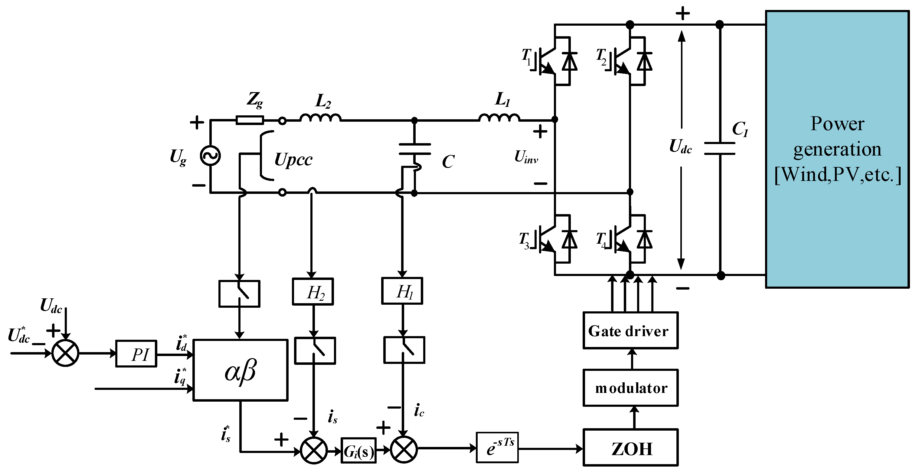
2. Model of a Single-Phase LCL-Type Grid-Connected Converter

Figure 1 shows a block diagram of a single-phase LCL-type grid-connected converter without PLL in weak grid conditions. The LCL filter consists of a converter-side inductor L1, a filter capacitor C, and a grid side inductor L2. C1 is the capacitor and load resistance of the DC-side. Power switches T1~T4 and their antiparallel diodes form the converter bridge. Zg is the grid impedance at the point of common coupling (PCC). Ug and Uinv represent the grid voltage and input of the converter bridge. H1 and H2 are the feedback coefficients of the capacitor and grid currents, respectively. Gi(s) is the grid current regulator transfer function.
The digital control methods have a one-beat hysteresis delay. A zero-order holder (ZOH) and a one-beat hysteresis link are added to the grid-connected converter model.
The transfer function of the ZOH is:
G h ( s ) = 1 e s T s / s T s e 0.5 s T s
The double closed-loop control structure on the voltage and current is used. The external DC voltage loop uses a PI controller to regulate the DC side voltage, which provides stable output for the d-axis reference current amplitude i d * , and the q-axis reference current i q * is given directly. The given reference current i s * is obtained by i d * and i q * . According to the requirements of the electrical energy conversion, the inner loop current S-domain model of the grid-connected current is established as shown in Figure 2.
In Figure 2, 1/Ts is the transfer function of the sampling switch [16], and K P W M = U d c * / U t r i , Utri represents the amplitude of the triangular carrier wave. The Simplified S-domain model is shown in Figure 3 [17].
In Figure 3,
G x 1 = G i Z C G Z K P W M Z L 1 + H 1 K P W M G Z + Z C
G x 2 = Z L 1 + H 1 K P W M G Z + Z C Z L 2 ( Z L 1 + H 1 K P W M G Z + Z C ) + Z L 1 Z C
G Z = 1 T s e s T s G h e 1.5 s T s
where Z L 1 = s L 1 ; Z L 2 = s L 2 ; Z C = 1 / s C .
The loop gain of the grid-connected current can be obtained as the following:
T i g = G x 1 G x 2 H 2
Thus, the grid connection current can be deduced as:
i s = G x 2 1 + T i g U P C C 1 H 2 T i g 1 + T i g i s *

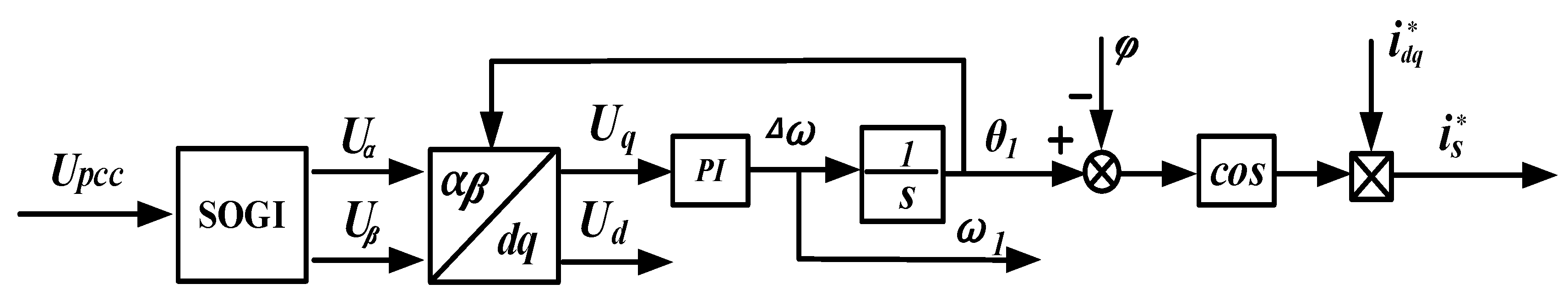
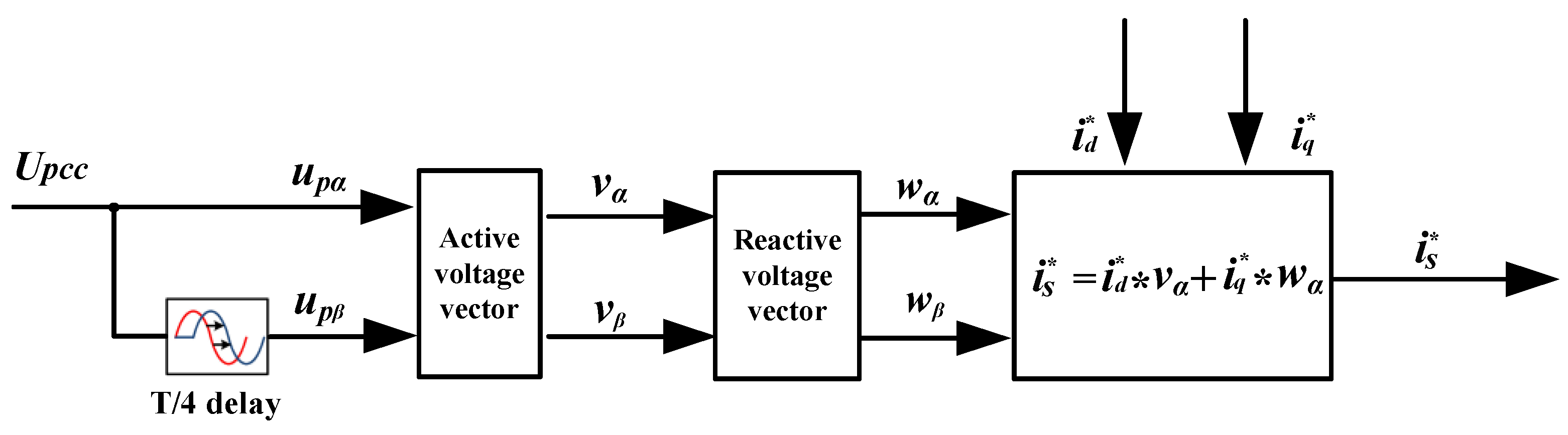
3. Control Strategies for Grid Currents

One of the most popular phase-locked methods is synchronous reference frame PLL (SRF-PLL) [18,19]. The control block diagram of the SRF-PLL is shown in Figure 4. In Figure 4, the AC voltage component with phase lag of 90° at the UPCC is generated by the OSG (Orthogonal Signal Generators) module. The orthogonal signals Uα and Uβ are transformed into the voltages Ud and Uq in the rotating frame system [20].
The characteristic transfer functions of SOGI are given by:
{ D ( s ) = U α U P C C = k ω 0 s s 2 + k ω 0 s + ω 0 2 Q ( s ) = U β U P C C = k ω 0 2 s 2 + k ω 0 s + ω 0 2
where ω0 and k are set as the resonance frequency and damping factor of the SOGI. It can be seen from Figure 4 that the reference current i s * is not an independent variable, and its expression is:
i s * = i d q * T PLL D ( s ) U P C C
where TPLL is the transfer function of the PLL, i d q * is the active and reactive reference current.
From the above discussion, one conclusion that can be drawn is that the stability of the current loop is affected by the PLL. This means that the traditional control strategy will become more complicated. Thus, it is difficult to guarantee its stability.
To address this problem, a control strategy without PLL is proposed. Considering that single-phase systems lack a degree of freedom, the control strategy based on the αβ frame is more compact than the method based on the dq frame. The αβ frame control strategy with voltage sampling signals can achieve independent control of active and reactive current by decomposing the voltage signal into instantaneous active and instantaneous reactive components. The orthogonal signal is generated by delaying the original single-phase signal by T/4, where T is the grid fundamental period [21]. The control model is shown in Figure 5.
Assuming that the grid voltage is clean and undistorted, the command current in αβ frames based on the grid voltage without PLL is calculated as:
[ i s α * i s β * ] = [ v α w α v β w β ] [ i d * i q * ]
where v = (vα,vβ)T is the active voltage unit vector in αβ frames, w = (wα,wβ)T is the reactive voltage unit vector in αβ frames. According to instantaneous power theory, the mathematical relationship between v and w is:
[ v α v β ] = 1 | u p | [ u p α u p β ]
[ w α w β ] = [ 0 1 1 0 ] [ v α v β ]
Define up = (u,u)T as the voltage vector in the αβ frame system, in which u is the same as UPCC. |up| represents its amplitude, which can be calculated from the amplitudes of uα and uβ:
| u p | = u p α 2 + u p β 2
Thus, the grid reference current can be quickly obtained from (9)~(12) as follows:
i s * = i s α * = i d * v α + i q * w α
As seen in Equation (13), the reference current i s * can be controlled independently by changing the active currents reference i d * and reactive currents reference i q * . When i q * = 0, the reference current i s * and the voltage UPCC are in the same frequency and phase, the phase lock can be realized without PLL. When i * d = 0, the phase difference between reference current and the voltage UPCC is 90°.

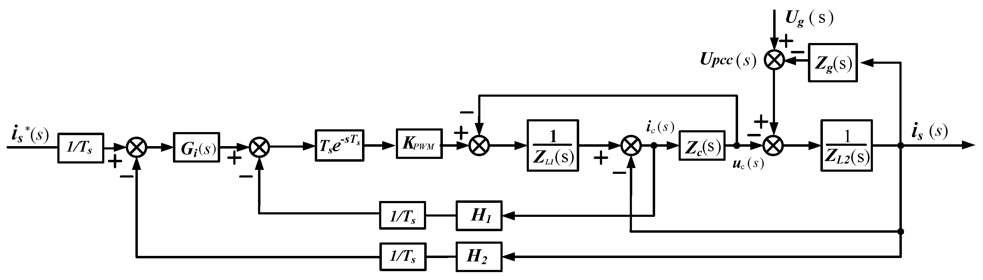
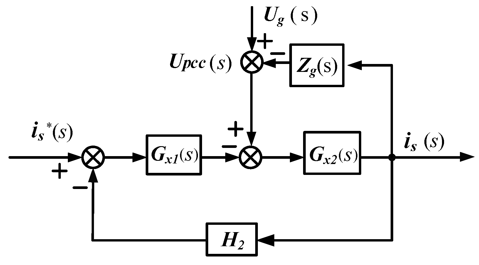
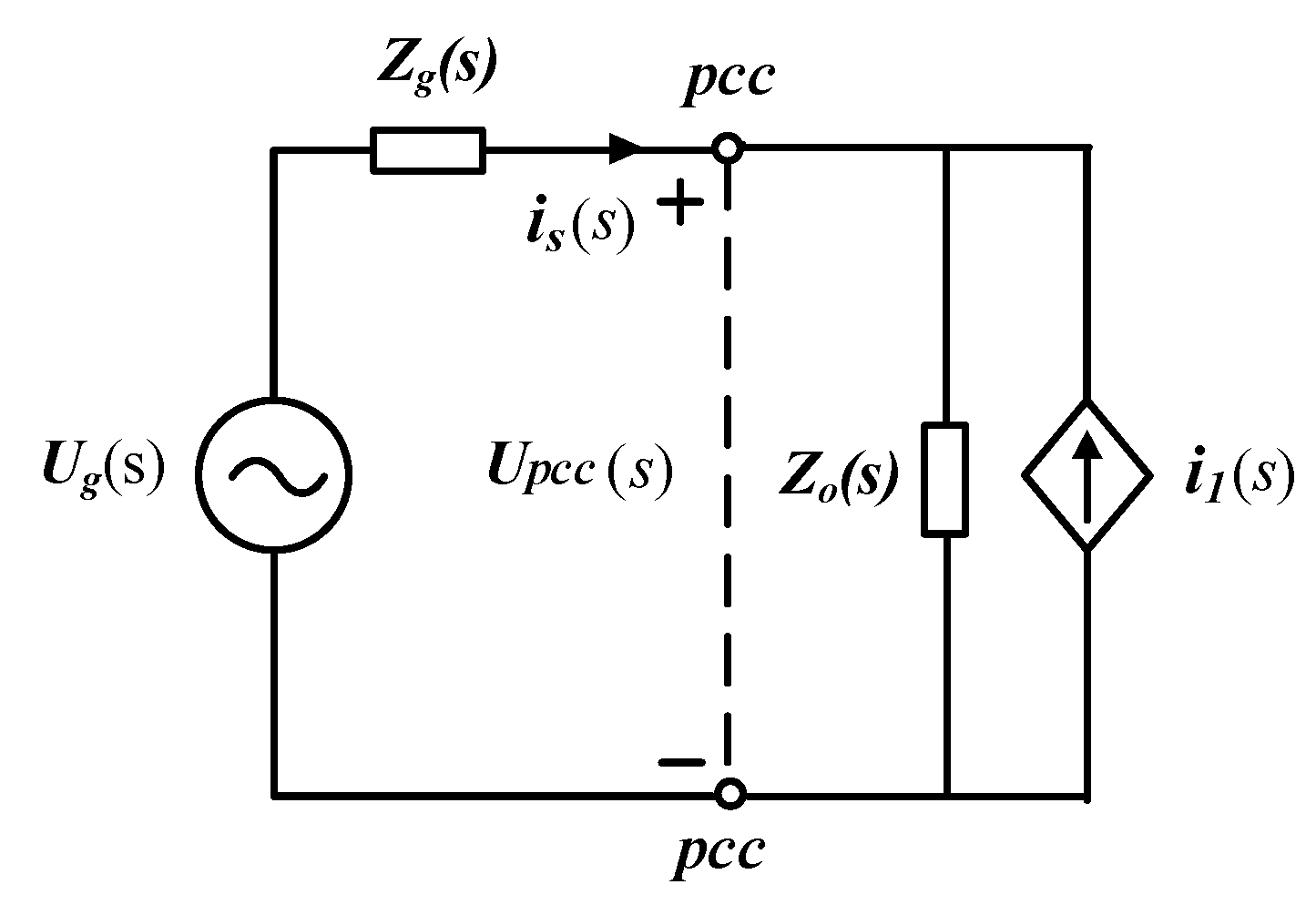
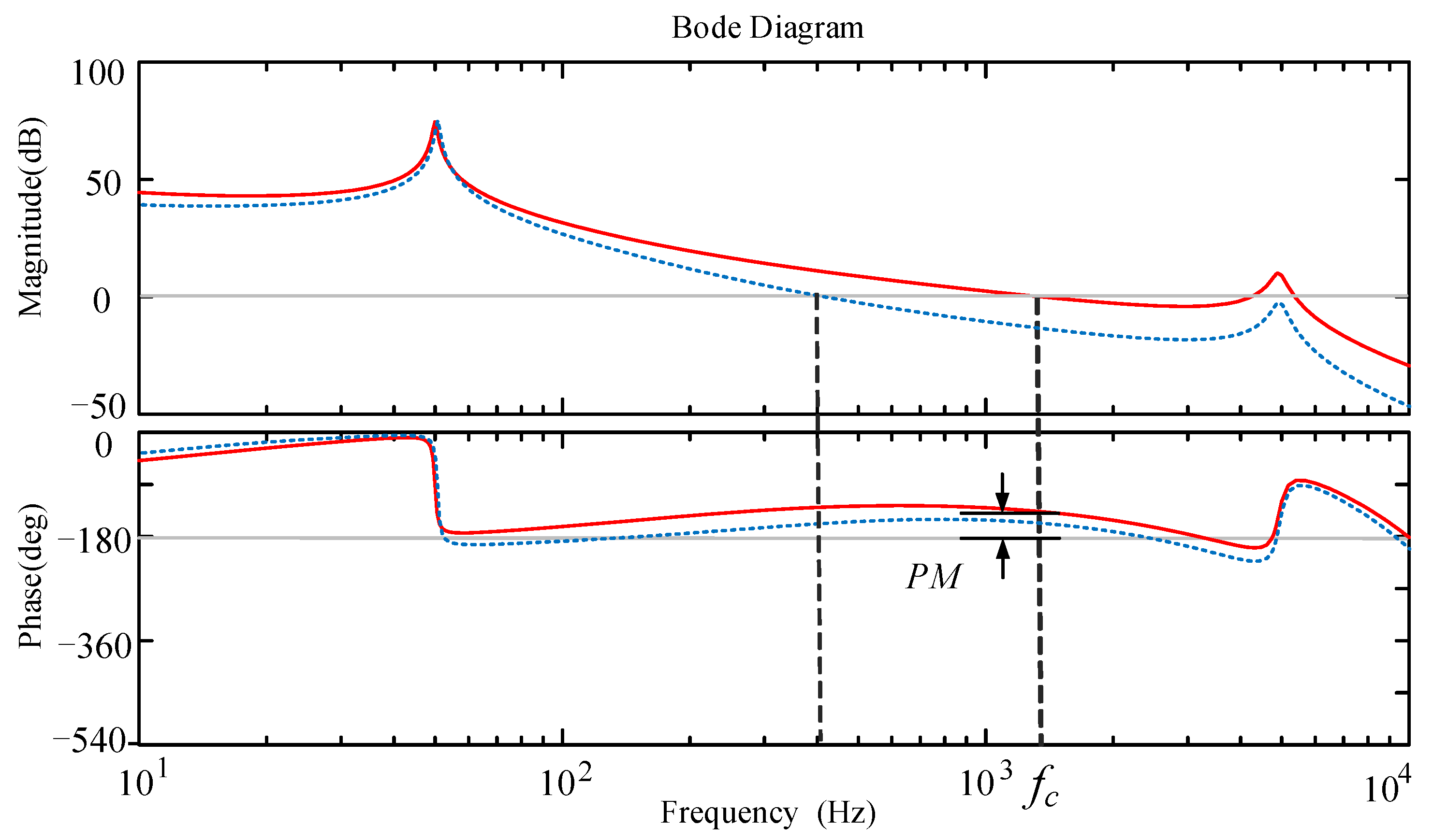
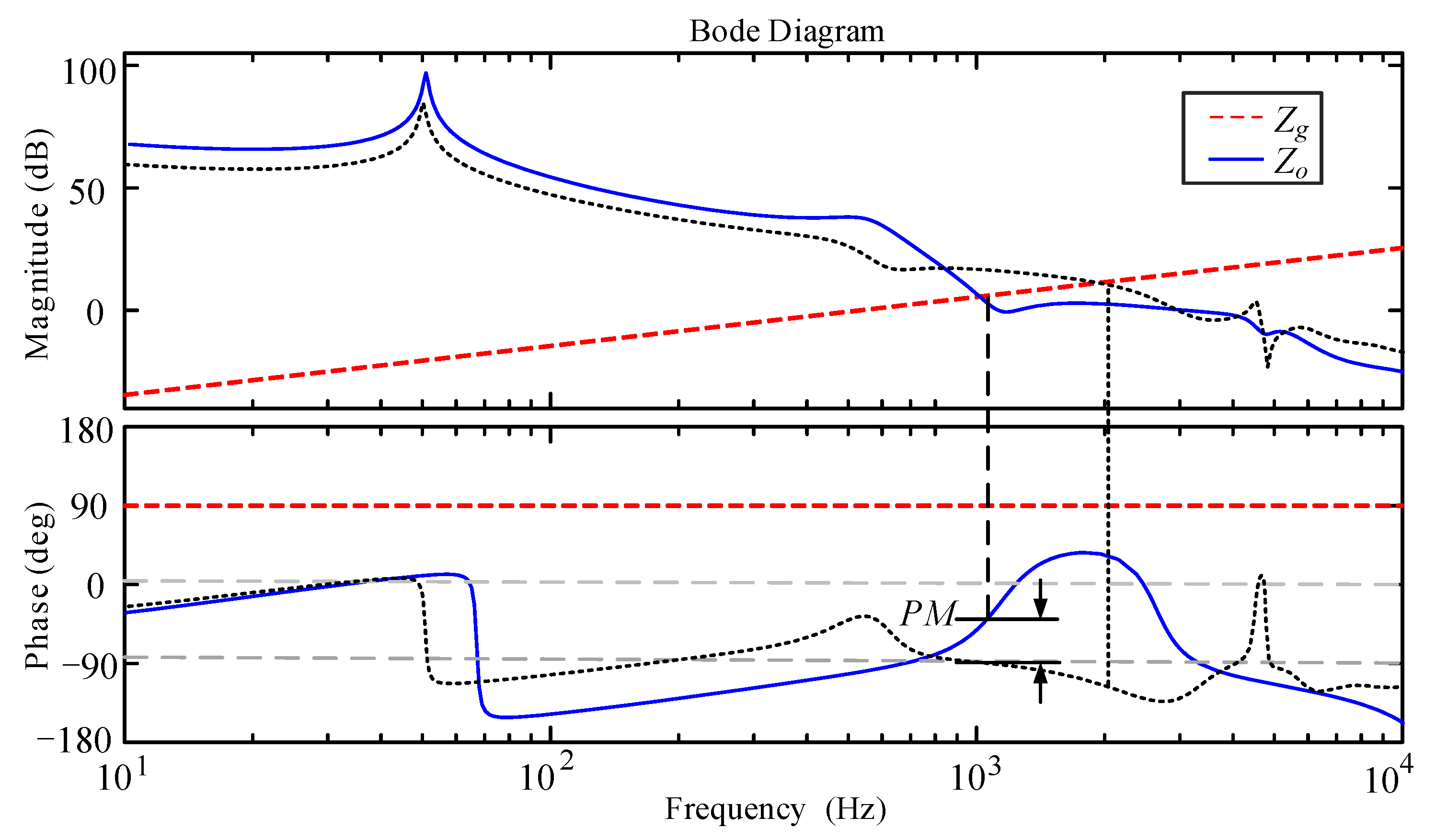
4. Stability Analysis

The grid-connected converter and the grid can be seen as a cascaded system with the grid existing impedance. Thus, Equation (6) can be rewritten as follows:
i s = U P C C Z o i 1
where i1 and Zo are the equivalent ideal current source and output impedance of the grid-connected converter, respectively:
Z o = 1 + T i g G x 2
i 1 = 1 H 2 T i g 1 + T i g i s *
The equivalent circuit of a single-phase LCL-type grid-connected converter connected to a weak grid can be obtained according to Equation (14), as shown in Figure 6. is(s) represents the grid connection current and Zg(s) is the grid impedance.
The expression for the grid connection current can be obtained as:
i s ( s ) = 1 Z o ( s ) + Z g ( s ) U g ( s ) Z o ( s ) Z o ( s ) + Z g ( s ) i 1 ( s ) = N ( s ) ( U g ( s ) Z o ( s ) i 1 ( s ) )
where:
N ( s ) = 1 1 + Z g ( s ) / Z o ( s )
It can be seen that the stability of the system depends on [Ug(s)/Zo(s) − i1(s)] and N(s). When Zg = 0, the grid-connected converter is a stable system, [Ug(s)/Zo(s) − i1(s)] does not contain a right-plane pole. For N(s), it is required that [Zg(s)/Zo(s)] satisfies the Nyquist stability criterion. Based on the above derivation, the stability of the grid-connected converter under weak grid conditions needs to satisfy the following two conditions:
(1)
The grid-connected converter is stable when Zg = 0;
(2)
The impedance ratio Zg(s)/Zo(s) satisfies the Nyquist stability criterion.
Condition (1) can be satisfied only by correcting the loop gain Tig. Condition (2) requires Zg(s)/Zo(s) to have a certain phase margin (PM) at 0 dB, which can be calculated as:
P M = | 180 ° + arg [ Z g ( j 2 π f i ) ] arg [ Z o ( j 2 π f i ) ] |
where fi is the crossover frequency, and the grid impedance Zg is generally resistive inductive [22]. Considering the worst case, the grid impedance is set as pure inductance. Thus, Equation (19) can be simplified to:
P M = 90 ° + arg [ Z o ( j 2 π f i ) ]
It must be ensured that PM is greater than 0°, so that the system is stable. It is necessary to make sure that the corresponding phase of Zo at each intercept frequency is greater than −90° when the amplitudes of Zg and Zo intersect multiple times. When the grid impedance changes, using this criterion to analyze the stability of the grid-connected converter, there is no need to re-model the grid-connected converter.

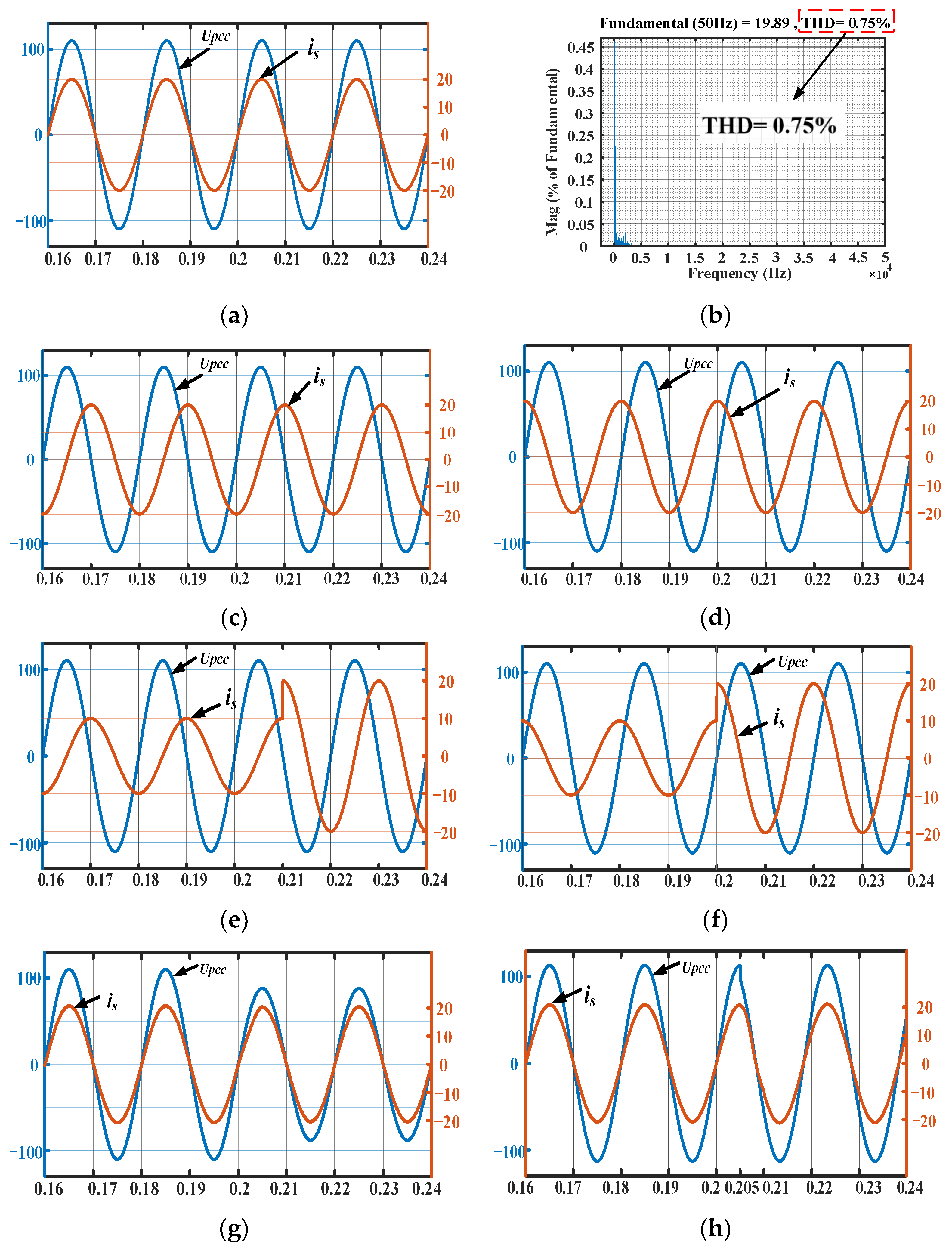
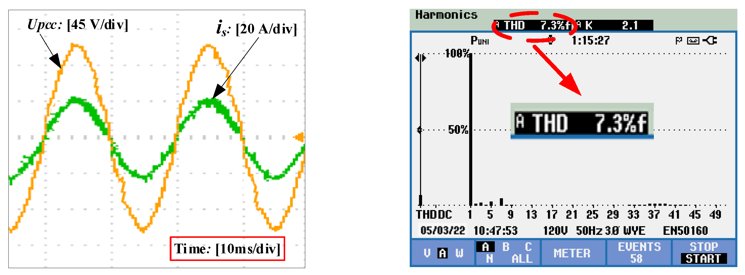
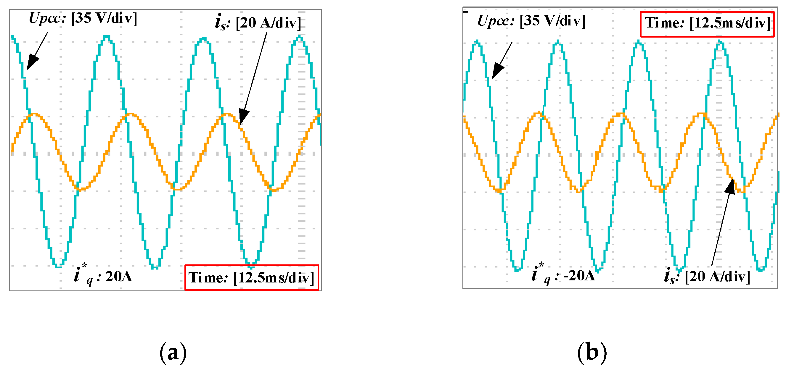
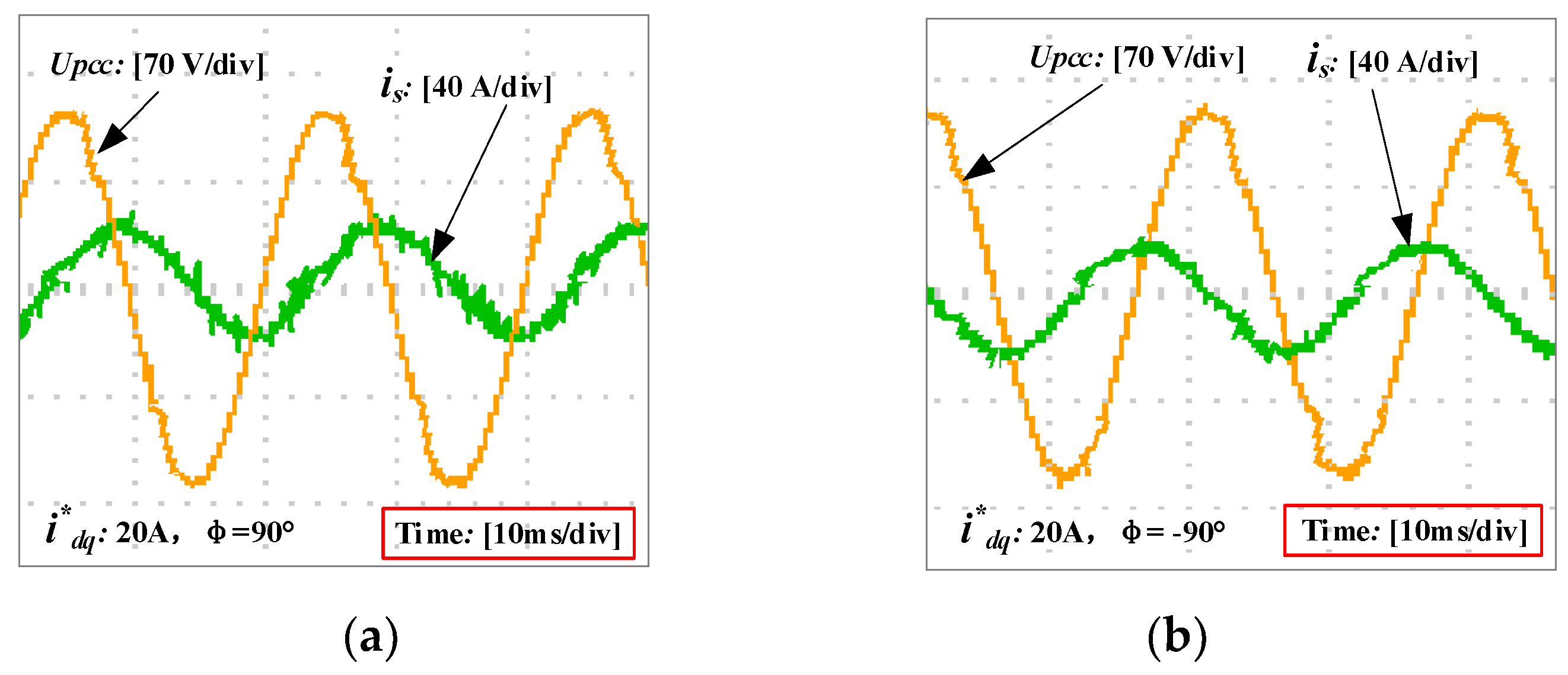
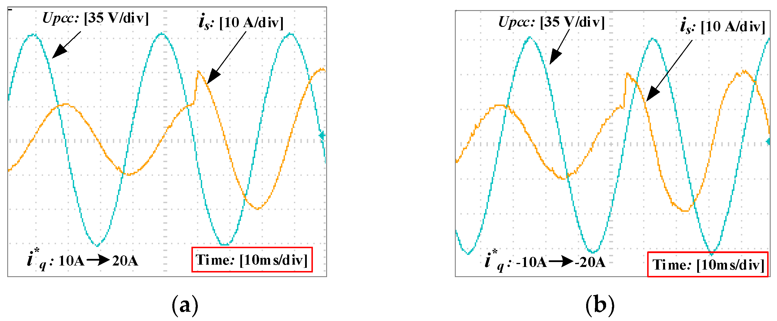
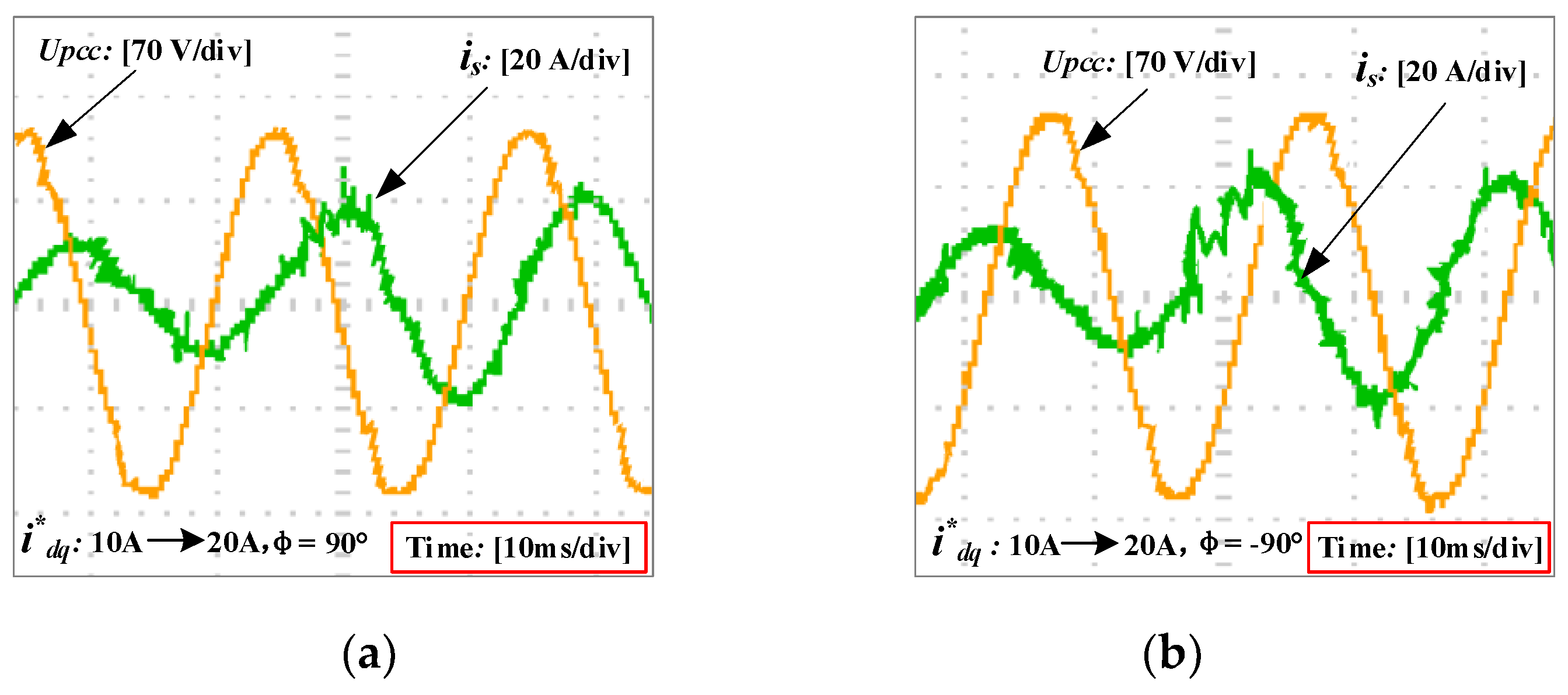
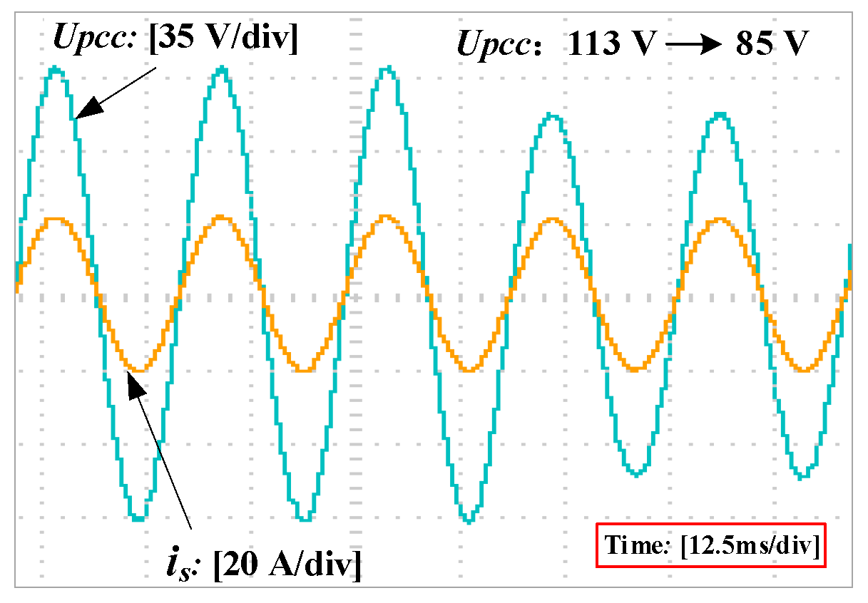
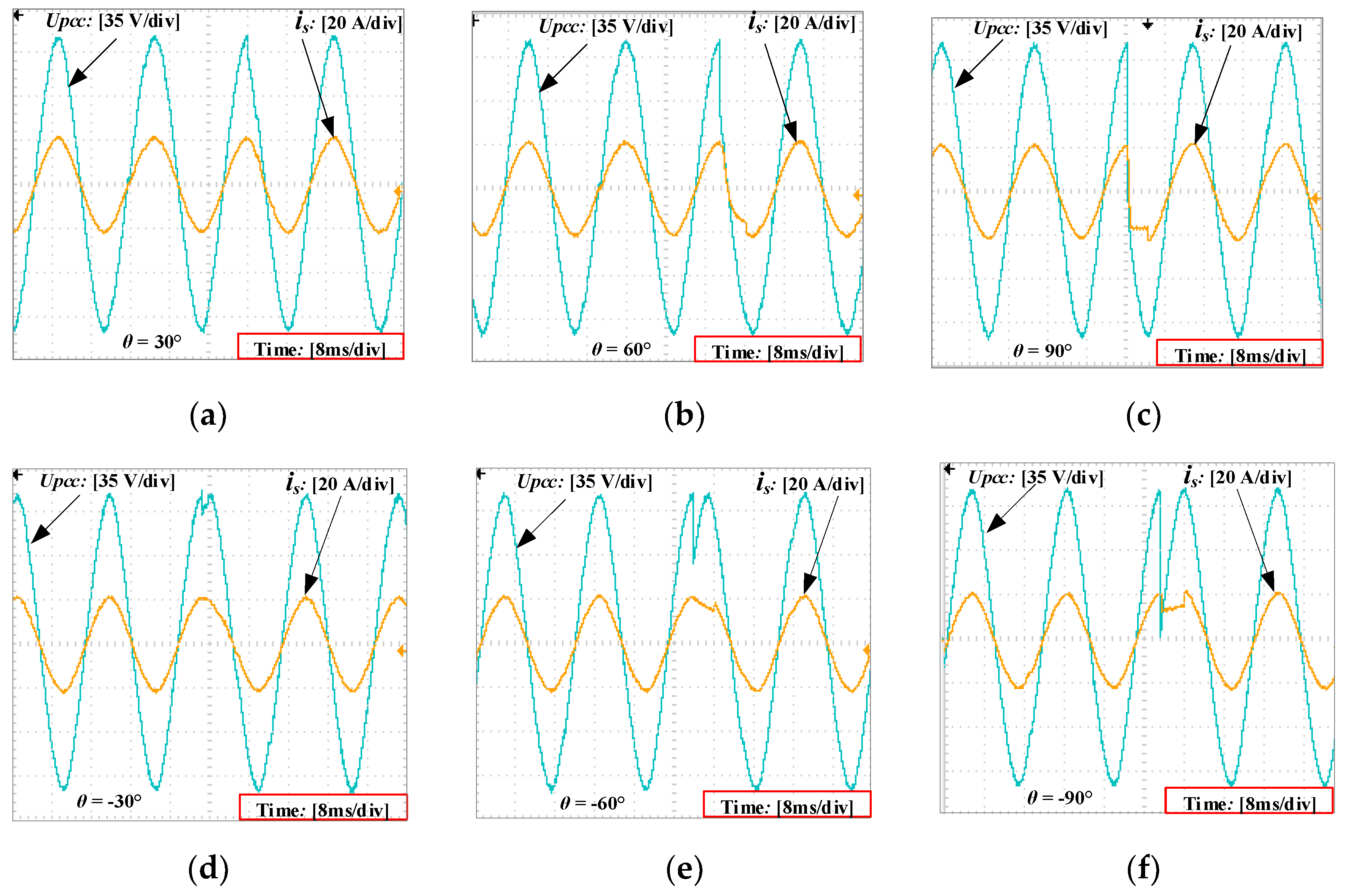
5. Simulation and Experimental Verification

5.1. Simulation

Simulation was carried out in the MATLAB/Simulink software. The parameters are shown in Table 1. The variation range of the grid impedance can be calculated from the short circuit ratio (SCR) at the PCC [23]. According to the definition of SCR, the maximal grid impedance is 1.8 mH.
A PR regulator with the following transfer function is used for the current regulator:
G i ( s ) = K p + 2 K r ω i s s + 2 ω i s + ω 0 2
The system current loop gain Tig can be rewritten as:
T i g ( s ) = G x 1 ( s ) G x 2 ( s ) H 2 = H 2 K P W M G i ( s ) G Z ( s ) s 3 L 1 L 2 C + s 2 L 2 C H 1 K P W M G Z ( s ) + s ( L 1 + L 1 )
The amplitude margins GM1 and GM2 of the system at fr and fs/6 are:
G M 1 = 20 lg | T i g ( j 2 π f r ) |
G M 2 = 20 lg | T i g ( j 2 π f s / 6 ) |
According to the method proposed in [24], Kp = 0.54, Kr = 115 and the capacitor current feedback coefficient H1 = 0.02.
The Bode diagram of the corrected grid-connected current loop gain is shown as the red solid line in Figure 7. It can be seen from Figure 7 that the phase margin PM = 51.5°, and the magnitude margins at fr and fs/6 are GM1 = −8.21 dB and GM2 = 3.46 dB, respectively. Therefore, the system is stable.
The Bode diagrams of Zg and Zo are shown in Figure 8, where the blue solid line represents Zo and the red dotted line represents Zg. From the Figure 8, it can be seen that the impedance crossover frequency is fi = 1030 Hz, the phase margin of the system is PM = 55.3°. Thus, the grid-connected converter system is still stable and has good robustness. Assuming that the system parameters are Kp = 0.14, Kr = 50, H1 = 0.01. The current loop gain is shown as the blue dotted line in Figure 7. We can see that the resonant peak is less than 0 dB, and GM1 = 0.16 dB and GM2 = −1.35 dB. The results violate Condition (1) in Section 4; thus, the current loop is unstable. The black dotted line in Figure 8 indicates that the PM of Zg and Zo at the intersection frequency is less than 0, which violates Condition (2) in Section 4, so the system will experience instability.
The waveforms of UPCC and is in different conditions with Zg =1.8 mH (corresponding to the short-circuit ratio SCR = 10) are shown in Figure 9. Figure 9a,b shows that the grid current and voltage are in the same frequency and phase without using the PLL control strategy. The grid current can track the active current reference rapidly and accurately. In addition, THD is only 0.75%. The system is stable and the power quality is good. Figure 9c, d illustrates that the grid current is able to track the inductive reactive current reference ( i q * = 20 A) and capacitive reactive current reference ( i q * = −20 A) in steady state. The phase difference between grid current and the voltage UPCC is 90°. Therefore, the proposed strategy satisfies steady-state performance. Figure 9e,f shows that when the reactive current reference i q * suddenly changes from 10 A to 20 A and −10 A to −20 A, the system responds quickly, and the tracking is rapid and smooth. Figure 9g,h show that when the amplitude and phase of the voltage are suddenly changed, the tracking is rapid too. It can be seen that the system has good dynamic performance.

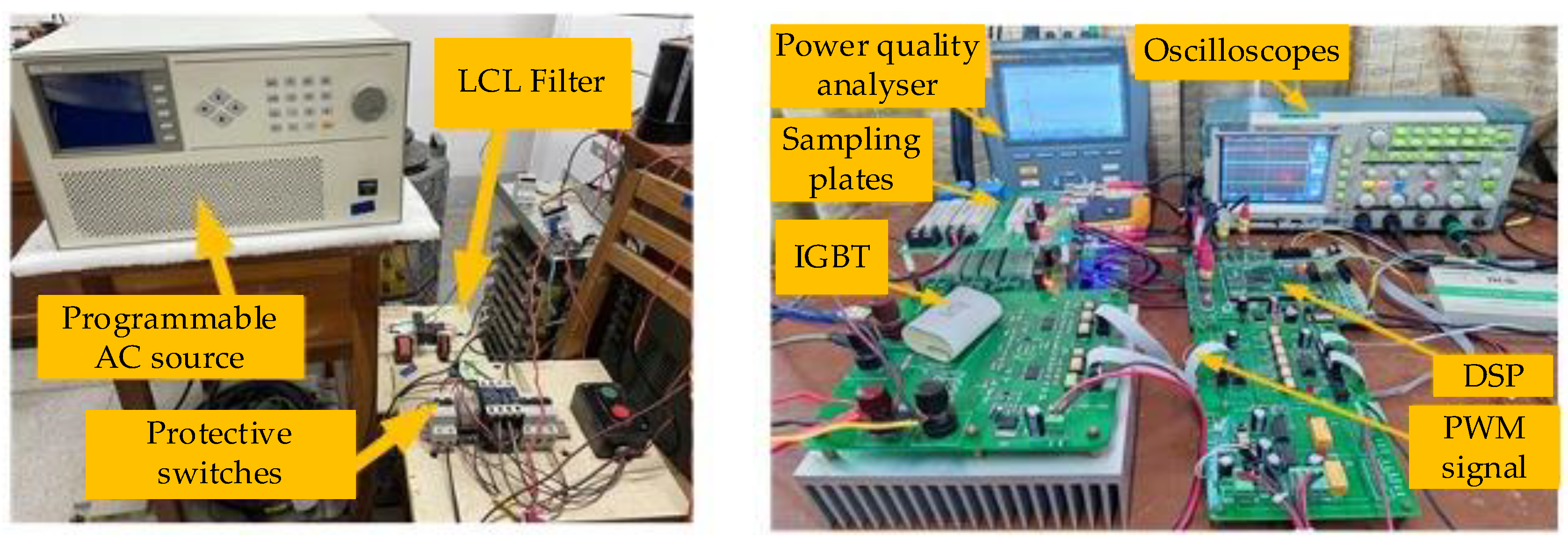
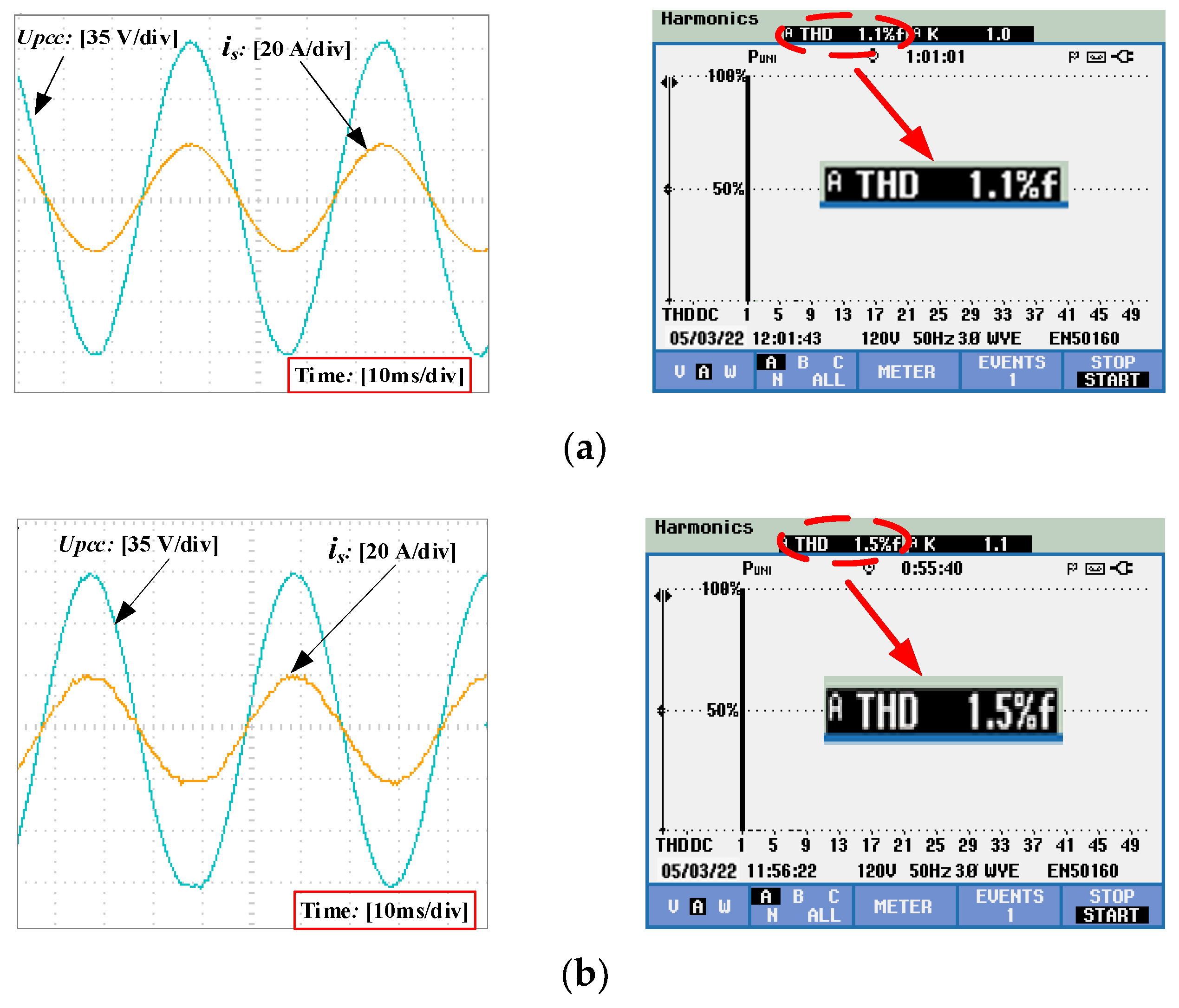
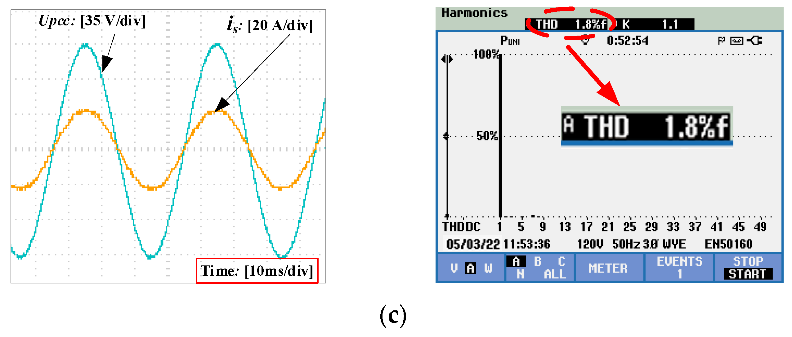
5.2. Experimental Verification

To further verify the effectiveness of the methods, a 1.1 kW LCL-type single-phase grid-connected converter was built, as shown in Figure 10. The parameters were the same as those in Table 1.
The electronic switches were Infineon IGBT module F4100R12KS4, and the DSP model was a 32-bit floating point digital signal processor TMS320F28377D. A programmable AC power supply (Chroma 6530) was used to generate sinusoidal grid voltage, and the impedance of the power grid was simulated by connecting inductor. There were four DSP built-in 16-bit ADC sampling modules, and Hall sensors were used to detect the grid voltage, grid current, and DC-side voltage signals.
Figure 11 shows the waveform of UPCC, is and the THD of the grid current with different grid impedances Zg.
From Figure 11a–c, we can see that the system worked stably when the grid impedance varied in the full range from 0 to 1.8 mH, and the THDs of the grid current were less than 1.8%. Table 2 shows that the third and fifth harmonic contents of the grid current were less than 1.1%. The proposed strategy was very stable under weak grid conditions.
Figure 12 shows the waveform of UPCC, is and the THD of the grid current under PLL control with Zg = 1.8 mH. It can be seen that the waveforms of the voltage and current are distorted, which indicate a poor harmonic suppression capability in the system, resulting in a large harmonic content of the grid current. The THD of the grid current is 7.3%, which is higher than the 5% defined by the electrical energy quality standard.
Comparing Figure 11c with Figure 12, it is obvious that the proposed method could effectively adapt to weak grid conditions, and the current is and voltage UPCC remained in the same frequency and phase. Furthermore, the proposed control method reduced the THD of the output current, increased the stability as well as the robustness of the system, and improves the power quality.
The waveforms of UPCC, is under different control methods with Zg = 1.8 mH are shown in Figure 13 and Figure 14. Figure 13a,b shows that the grid current tracked the reactive current reference with smooth waveform and lower harmonic content at steady state. In Figure 14a,b, the grid current has a certain degree of distortion and poor steady-state performance. A number of burrs in the waveforms suggest that PLL affected the output impedance of the system, which had a serious impact on the stability of the inner loop current. The comparison verified that the proposed method had stronger harmonic suppression ability, so as to better realize the function of reactive power compensation.
Figure 15 and Figure 16 show the waveforms of UPCC and is under different controls, with the reactive current reference i q * changing suddenly.
Figure 15 shows that the actual current rose rapidly without any time delay or overshoot during the dynamic process under weak grid conditions. The steady-state current before and after the transient state was stable in amplitude and 90° ahead or behind the voltage in phase. Thus, the proposed control method without PLL had good steady-state and dynamic performance. In contrast, Figure 16 shows a slow transient response of the system. When the reactive current i q * changed suddenly, the grid current needed a delay of at least 5 ms before it was completely tracked. Obviously, the control strategy without PLL was more suitable than the PLL control strategy in weak grid conditions.
The waveforms of UPCC and is with UPCC suddenly dropping from 113 V to 85 V are shown in Figure 17. It can be seen that when the grid voltage changed suddenly, the amplitude and phase of the grid current did not change. The grid current remained stable.
Figure 18 shows that when the phase of the voltage was suddenly changed at a certain moment, the tracking was rapid. The current and voltage was able to maintain the same frequency and phase after the change of phase. When θ = ±30°, the current could track the phase in a very short time, and when a = ±60° or ±90°, the tracking process would not exceed T/4 (5 ms). It is shown that the proposed method is feasible under weak grid conditions.

6. Conclusions

The stability of a single-phase LCL-Type grid-connected converter under weak grid conditions was analyzed. Two conditions for the stability of the grid-connected converter under weak grid needs to satisfy were derived. A control strategy without PLL was proposed. The strategy decomposed the voltage signal into instantaneous active and instantaneous reactive components through the αβ frame, which realized the independent control of active and reactive current. Simulations and experiments were carried out. Based on the obtained results, the following conclusions can be drawn:
(1)
The proposed control strategy can effectively avoid the harmonic and instability problems caused by PLL under weak grid conditions. The THD of the grid current is less than 1.8% and the third and fifth harmonic contents are less than 1.1%. Compared with the traditional control strategy, it has better steady-state performance and stronger robustness.
(2)
This method does not need Park transforms and PLL, which reduces the computation and complexity and is beneficial to digital realization.
(3)
When the reactive current or the grid voltage changes suddenly, the system can respond quickly, and the tracking is fast. The system has better dynamic performance.

Author Contributions

Project administration, L.X.; writing—original draft preparation, S.Z.; investigation, Z.Z. and J.L.; validation, J.Y. All authors have read and agreed to the published version of the manuscript.

Funding

This research was funded by National Natural Science Foundation of China, grant number 61861003.

Data Availability Statement

The data presented in this study are available on request from the corresponding author.

Acknowledgments

This study was supported by National Natural Science Foundation of China, grant number 61861003.

Conflicts of Interest

The authors declare no conflict of interest.

References

  1. Priyadarshi, N.; Bhaskar, M.S.; Azam, F.; Singh, M.; Dhaked, D.K.; Taha, I.B.M.; Hussien, M.G. Performance Evaluation of Solar-PV-Based Non-Isolated Switched-Inductor and Switched-Capacitor High-Step-Up Cuk Converter. Electronics 2022, 11, 1381. [Google Scholar] [CrossRef]
  2. Maganti, S.; Padhy, N.P. A Flexible Compensation Strategy for Weak Grid-Tied Current Controlled Converters under Unbalanced and Harmonic Conditions. In Proceedings of the 2020 IEEE International Conference on Power Electronics, Drives and Energy Systems (PEDES), Jaipur, India, 16–19 December 2020; pp. 1–5. [Google Scholar] [CrossRef]
  3. Lin, P.; Zhang, C.; Wang, P.; Li, X.; Xiao, J.; Tu, P.; Hoong, C.F. A global robust output regulation method for grid-connected inverter with LCL filter in weak grid condition. In Proceedings of the 2017 12th IEEE Conference on Industrial Electronics and Applications (ICIEA), Siem Reap, Cambodia, 18–20 June 2017; pp. 1646–1651. [Google Scholar] [CrossRef]
  4. Sedo, J.; Kascak, S. Control of single-phase grid connected inverter system. In Proceedings of the 2016 ELEKTRO, Strbske Pleso, Slovakia, 16–18 May 2016; pp. 207–212. [Google Scholar] [CrossRef]
  5. Wu, H.; Wang, X. Design-Oriented Transient Stability Analysis of PLL-Synchronized Voltage-Source Converters. IEEE Trans. Power Electron. 2019, 35, 3573–3589. [Google Scholar] [CrossRef] [Green Version]
  6. Fang, J.; Li, X.; Li, H.; Tang, Y. Stability Improvement for Three-Phase Grid-Connected Converters through Impedance Reshaping in Quadrature-Axis. IEEE Trans. Power Electron. 2017, 33, 8365–8375. [Google Scholar] [CrossRef]
  7. Zhu, D.; Zhou, S.; Zou, X.; Kang, Y.; Zou, K. Small-Signal Disturbance Compensation Control for LCL-Type Grid-Connected Converter in Weak Grid. IEEE Trans. Ind. Appl. 2020, 56, 2852–2861. [Google Scholar] [CrossRef]
  8. Yang, D.; Wang, X.; Liu, F.; Xin, K.; Liu, Y.; Blaabjerg, F. Symmetrical PLL for SISO Impedance Modeling and Enhanced Stability in Weak Grids. IEEE Trans. Power Electron. 2019, 35, 1473–1483. [Google Scholar] [CrossRef]
  9. Zhu, D.; Zhou, S.; Zou, X.; Kang, Y. Improved Design of PLL Controller for LCL-Type Grid-Connected Converter in Weak Grid. IEEE Trans. Power Electron. 2019, 35, 4715–4727. [Google Scholar] [CrossRef]
  10. Zhou, J.Z. Impact of short circuit ratio and phase locked loop parameters on the small-signal behaviour of a VSC-HVdc converter. In Proceedings of the 2016 IEEE Power and Energy Society General Meeting (PESGM), Boston, MA, USA, 17–21 July 2016; p. 1. [Google Scholar] [CrossRef]
  11. Wu, X.; Huang, T.; Chen, X.; Hu, H.; He, G. Frequency Characteristic and Impedance Analysis on Three-Phase Grid-Connected Inverters Based on DDSRF-PLL. In Proceedings of the 2019 10th International Conference on Power Electronics and ECCE Asia (ICPE 2019—ECCE Asia), Busan, Korea, 27–31 May 2019. [Google Scholar] [CrossRef]
  12. Scoltock, J.; Geyer, T.; Madawala, U.K. Model Predictive Direct Power Control for Grid-Connected NPC Converters. IEEE Trans. Ind. Electron. 2015, 62, 5319–5328. [Google Scholar] [CrossRef]
  13. Zhang, L.; Harnefors, L.; Nee, H.-P. Power-Synchronization Control of Grid-Connected Voltage-Source Converters. IEEE Trans. Power Syst. 2009, 25, 809–820. [Google Scholar] [CrossRef]
  14. Sun, Y.; Li, S. Comparison of conventional and a novel direct-current vector control for a LCL-filter based VSC-converter connected to weak grid. In Proceedings of the 2016 IEEE Power and Energy Society General Meeting (PESGM), Boston, MA, USA, 17–21 July 2016; pp. 1–5. [Google Scholar] [CrossRef]
  15. Li, Z.; Yang, L.; Yang, D.; Peng, Z.; Shao, D.; Liu, J. Indirect Current Control Method Based on Reference Current Compensation of an LCL-Type Grid-Connected Inverter. Energies 2022, 15, 965. [Google Scholar] [CrossRef]
  16. Agorreta, J.L.; Borrega, M.; López, J.; Marroyo, L. Modeling and Control of $N$ -Paralleled Grid-Connected Inverters with LCL Filter Coupled Due to Grid Impedance in PV Plants. IEEE Trans. Power Electron. 2010, 26, 770–785. [Google Scholar] [CrossRef]
  17. Wang, X.; Ruan, X.; Liu, S.; Tse, C.K. Full Feedforward of Grid Voltage for Grid-Connected Inverter with LCL Filter to Suppress Current Distortion Due to Grid Voltage Harmonics. IEEE Trans. Power Electron. 2010, 25, 3119–3127. [Google Scholar] [CrossRef]
  18. Rodriguez, P.; Pou, J.; Bergas, J.; Candela, J.I.; Burgos, R.P.; Boroyevich, D. Decoupled Double Synchronous Reference Frame PLL for Power Converters Control. IEEE Trans. Power Electron. 2007, 22, 584–592. [Google Scholar] [CrossRef]
  19. Rodríguez, P.; Luna, A.; Candela, I.; Mujal, R.; Teodorescu, R.; Blaabjerg, F. Multiresonant Frequency-Locked Loop for Grid Synchronization of Power Converters under Distorted Grid Conditions. IEEE Trans. Ind. Electron. 2010, 58, 127–138. [Google Scholar] [CrossRef] [Green Version]
  20. Zhang, Z.; Gercek, C.; Renner, H.; Reinders, A.; Fickert, L. Resonance Instability of Photovoltaic E-Bike Charging Stations: Control Parameters Analysis, Modeling and Experiment. Appl. Sci. 2019, 9, 252. [Google Scholar] [CrossRef]
  21. Golestan, S.; Guerrero, J.M.; Vidal, A.; Yepes, A.G.; Doval-Gandoy, J.; Freijedo, F.D. Small-Signal Modeling, Stability Analysis and Design Optimization of Single-Phase Delay-Based PLLs. IEEE Trans. Power Electron. 2015, 31, 3517–3527. [Google Scholar] [CrossRef] [Green Version]
  22. Liserre, M.; Teodorescu, R.; Blaabjerg, F. Stability of photovoltaic and wind turbine grid-connected inverters for a large set of grid impedance values. IEEE Trans. Power Electron. 2006, 21, 263–272. [Google Scholar] [CrossRef]
  23. Strachan, N.P.W.; Jovcic, D. Stability of a Variable-Speed Permanent Magnet Wind Generator with Weak AC Grids. IEEE Trans. Power Deliv. 2010, 25, 2779–2788. [Google Scholar] [CrossRef]
  24. Wang, X.; Ruan, X.; Bao, C.; Pan, D.; Xu, L. Design of the PI regulator and feedback coefficient of capacitor current for grid-connected inverter with an LCL filter in discrete-time domain. In Proceedings of the 2012 IEEE Energy Conversion Congress and Exposition (ECCE), Raleigh, NC, USA, 15–20 September 2012; pp. 1657–1662. [Google Scholar] [CrossRef]
Figure 1. Structure diagram of LCL-Type grid-connected converter without PLL in weak gird conditions.
Electronics 11 03322 g001
Figure 2. S-domain model of grid-connected current.
Electronics 11 03322 g002
Figure 3. Simplified S-domain model of grid-connected current.
Electronics 11 03322 g003
Figure 4. Phase locked loop control model.
Electronics 11 03322 g004
Figure 5. Control model in αβ frames.
Electronics 11 03322 g005
Figure 6. Equivalent circuit of grid-connected system.
Electronics 11 03322 g006
Figure 7. Bode diagram of the loop gain.
Electronics 11 03322 g007
Figure 8. Bode diagram of Zg and Zo.
Electronics 11 03322 g008
Figure 9. Waveforms of UPCC and is. (a) Steady-state; (b) THD of grid current; (c) Inductive reactive current; (d) Capacitive reactive current; (e) Reactive current changes from 10 A to 20 A; (f) Reactive current changes from −10 A to −20 A; (g) UPCC suddenly dropping; (h) The phase of UPCC suddenly jumping (30°).
Electronics 11 03322 g009
Figure 10. Experimental setup of the grid-connected converter.
Electronics 11 03322 g010
Figure 11. Waveform of UPCC, is and the THD of the grid current with different Zg. (a) Zg = 0 mH; (b) Zg = 0.9 mH; (c) Zg = 1.8 mH.
Electronics 11 03322 g011aElectronics 11 03322 g011b
Figure 12. Waveform of UPCC, is and the THD of the grid current under PLL control with Zg = 1.8 mH.
Electronics 11 03322 g012
Figure 13. Waveforms of UPCC and is without PLL. (a) Inductive reactive current; (b) capacitive reactive current.
Electronics 11 03322 g013
Figure 14. Waveforms of UPCC and is with PLL. (a) Inductive reactive current; (b) capacitive reactive current.
Electronics 11 03322 g014
Figure 15. Waveforms of UPCC and is without PLL when Zg = 1.8 mH. (a) i q * changes from 10 A to 20 A; (b) i q * changes from −10 A to −20 A.
Electronics 11 03322 g015
Figure 16. Waveforms of UPCC and is with PLL when Zg = 1.8 mH. (a) i d q * changes from 10 A to 20 A, φ = 90°; (b) i d q * changes from 10 A to 20 A, φ = −90°.
Electronics 11 03322 g016
Figure 17. Waveforms of UPCC and is with UPCC suddenly dropping from 113 V to 85 V when Zg = 1.8 mH.
Electronics 11 03322 g017
Figure 18. Waveforms of UPCC and is with the phase of UPCC suddenly jumping. (a) θ = 30°; (b) θ = 60°; (c) θ = 90°; (d) θ = −30°; (e) θ = −60°; (f) θ = −90°.
Electronics 11 03322 g018
Table 1. Parameters of system.
ParametersValues
Ug80 V
U d c * 150 V
fo50 Hz
fs20 kHz
fsw10 kHz
L1300 μH
C10 μF
L2180 μH
Utri3 V
H20.14
C110,000 μF
RL40 Ω
Table 2. 3rd and 5th harmonics in all cases.
3rd5th
Zg = 0 mH0.78%0.49%
Zg = 0.9 mH0.95%0.58%
Zg = 1.8 mH1.06%0.69%
Publisher’s Note: MDPI stays neutral with regard to jurisdictional claims in published maps and institutional affiliations.

