Article

Conception and Experimental Validation of a Standalone Photovoltaic System Using the SUPC5 Multilevel Inverter

1
Electrical Engineering Department, L’école Supérieure de Technologie (EST), University Moulay Ismail, Meknes 50000, Morocco
2
Ecole de Technologie Superieure (ETS), Montreal, QC 11290, Canada
*
Authors to whom correspondence should be addressed.
Electronics 2022, 11(17), 2779; https://doi.org/10.3390/electronics11172779
Submission received: 26 July 2022 / Revised: 30 August 2022 / Accepted: 30 August 2022 / Published: 3 September 2022

Abstract

:
In this work, an advanced pulse width modulation (PWM) technique was developed to provide the auto-balancing of the capacitors voltages of the five-level split-packed U-Cells (SPUC5) single-phase inverter, and then, the latter was applied to a photovoltaic (PV) system in standalone mode to evaluate its performance in this kind of application. The SPUC5 inverter makes use of only five switches (four active bidirectional switches and one four quadrant switch), one DC source and two capacitors to generate five levels of output voltage and a current with a quasi-sinusoidal waveform which reduces the total harmonic distortion (THD) without the need to add filters or sensors, and also reduces its cost compared to the other multilevel inverters. In the proposed system; the incremental conductance (INC) algorithm is combined with a DC/DC boost converter to reach the maximum power (MP) of the PV array by tracking the MP point (MPP). The offered concept has been constructed and then simulated in the MATLAB/Simulink environment to evaluate its efficiency. According to the results, the self-balancing of the capacitors voltages has been achieved. A comparative study was performed with the traditional PWM technique. The proposed PV system has been validated by experimental results.

1. Introduction

Renewable energies are characterized by the fact that they are collected from cleaner sources. Moreover, they are inexhaustible and noiseless, unlike fossil energies that pollute the atmosphere and whose quantity on earth is limited. All these reasons give rise to several renewable energy projects in general and to photovoltaic solar energy in particular.
The solar energy field is the most targeted by researchers in alternative energy. There is about 1.2 × 10⁵ TW of solar irradiance that covers the global surface of the planet [1]. Photovoltaic cells make use of the photo-electric effect to deliver a direct current by collecting solar radiation. This effect enables the cells to directly convert the light energy of photons into electrical energy thanks to a semiconductor material that carries electrical charges. Therefore, irradiation and temperature are two factors that influence the produced power, which requires the use of the MPP tracking (MPPT) controller to extract the maximum power even under changing input conditions [2]. Various algorithms and methods have been developed to reach the MPP of the PV panels.
In [3,4], the perturb and observe (P and O) method is used to reach the MPP, it involves comparing the actual value of the PV array output power with the previous value while perturbing the PV array voltage. While the incremental conductance (INC) is utilized in [5,6], which uses the incremental and the instantaneous conductance of the PV array, the MPP is then reached when the slope of the PV array is null. The hill climbing (HC) technique consists of imposing a perturbation in the cyclic ratio of the boost converter to find the MPP [7]. In this study, the INC algorithm is employed to optimize the power of the PV array.
The inverter is also one of the important elements in a PV system; it transforms DC voltage into AC voltage to supply the load. There are two types of inverters: two-level inverters [8] and multilevel inverters [9,10]. The latter type produces low harmonic values and achieves high performance compared to the first type. For these reasons, various multilevel inverter topologies have been developed by researchers, such as cascaded H-bridge (CHB) [11], neutral point clamped (NPC) [12,13] and flying capacitor (FC) [14,15]. However, these traditional topologies have many drawbacks. For example, the NPC inverter needs a diversity of diodes. Hence, in these past years, new topologies have been implemented such as packed U-Cells (PUC) [16,17] and SPUC [18] which comes as a modification of the PUC inverter, which needs a limited count of switches and guarantees high performance in both PV systems [19,20].
Several techniques have been developed to control the DC/AC converters. In [21] a control based on the proportional-integral passivity-based controller (PI-PBC) is used to control the inverter. In [22], a technique has been developed to be used with all electrical devices that use the traditional PWM controllers to increase the efficiency and accuracy of the latter.
In [18], the SPUC9 inverter was controlled by the traditional PWM, it uses more redundant states and reduces the number of levels to achieve the self-balancing of capacitors voltages. It allows, in this case, nine levels of operation with three redundant states. However, this method allows THD rite to be more than 4%. In this paper, an advanced PWM control technique has been proposed and applied to the SPUC5 inverter to properly regulate and attain the self-balancing of the capacitors’ voltages and an output current with a quasi-sinusoidal waveform, which reduces the THD in comparison with the previous PWM technique.
This article proceeds in the following sections. First, the SPUC5 inverter associated with the proposed control technique is presented in Section 2. Afterward, the proposed PV system is described in Section 3. Subsequently, the results of the simulation are analyzed in Section 4. Finally, the experimental validation is carried out in Section 5.

2. The Proposed Control Technique of the SPUC5 Inverter

Among the newest developed multilevel inverters, we find the SPUC inverter. It is highly efficient and very competitive. Indeed, it outputs five voltage levels with only a single DC supply and two capacitors, as illustrated in Figure 1. The self-balancing of the capacitors’ voltages is ensured by the proposed control technique.
Table 1 shows the switching states of the SPUC5 inverter, where VC1 = VC2 = E/2 (VC1 and VC2 are the voltage of capacitor 1 and capacitor 2, respectively). In order to generate gate pulses, one has to design a specific modulation technique. Consequently, in this paper, the authors propose the following procedure in which a sign function of the reference voltage is used to determine S1.
Sign   ( v r ) = { 1 , v r 0 0 , v r < 0
S 1 = Sign   ( v r )
Four triangular carriers were designed to provide the remaining gate pulses. Their comparison to the reference voltage gives four signals as follow:
Z 1 = { 1 , C r 1 v r 0 , C r 1 < v r
Z 2 = { 1 , C r 2 v r 0 , C r 2 < v r
Z 3 = { 1 , C r 3 v r 0 , C r 3 < v r
Z 4 = { 1 , C r 4 v r 0 , C r 4 < v r
where vr presents the reference volage, Z1, Z2, Z3 and Z4 are the comparison results between the reference and carried triangular 1, 2, 3 and 4, respectively; Cr1, Cr2, Cr3 and Cr4 present the carried triangular 1, 2, 3 and 4, respectively.
A staircase signal which the image of the voltage load can then be generated by summing these equations as follows:
SS = Z 1 + Z 2 + Z 3 + Z 4
Figure 2 illustrates these signals. The remaining gate pulses can then be expressed as follows.
S 2 = Z 4 ¯
S 3 = 1 Sign   ( v r )
S 4 = Z 1 + ( Z 2 Z 3 )
S 5 = ( Z 1 Z 2 ) + ( Z 3 Z 4 )
Finally, Figure 2 describes the proposed control technique. It permits the self-balancing of the capacitors’ voltages in open loop operation with no need for a sensor.

3. The Suggested Photovoltaic System

The proposed PV system is composed of the PV panels, the DC/DC boost converter with the MPPT controller, and the SPUC5 inverter, which provides an RL load. The resistance and the inductance present the eventual active and passive power consumed by the load, respectively.

3.1. The PV Array under Consideration

The PV module is constructed of multiple interconnected cells. The latter is formed by interconnected photodiodes that are capable of converting solar irradiation into a DC current flow, which is called the photovoltaic effect.
A standard PV cell is schematically represented by a source of current linked in parallel with an ideal diode, and two resistors in serial connection, as shown in Figure 3.
Its mathematical model is written in the following equation:
I = I ph I 0 [ exp ( V + IR S nV T ) 1 ] V + IR S R Sh
where I [A] presents the output cell current, Iph [A] is the photocurrent produced by the photons, I0 [A] is the saturation current of the cell during the dark moments, V [V] presents the output voltage of cell, VT = kTc/q [V] is the thermal voltage of cell, n is the ideality factor of the diode, Rs [Ω] is the sum of the series resistors, and Rsh [Ω] represents the shunt resistance.
Table 2 shows the SunPower SPR-305-WHT panel characteristics. SunPower technology has been preferred because, over its outstanding 35 years of solar expertise, it has been awarded more than 900 patents. Figure 4 shows the P-V and I-V characteristics of the considered PV array and the corresponding MPP values for four various irradiances.

3.2. The Utilized MPPT Controller

The DC/DC boost converter offers multiple benefits to PV systems [23]: it regulates the electrical power in the DC chain and magnifies the PV voltage. Duo to varying weather conditions (in terms of irradiation and temperature), P-V and I-V characteristics have unique MP points. The latter should be found and tracked by the designed MPPT technique. The INC technique has been preferred because of its simplicity and accuracy. It is a question of finding the point at which the derivative of power toward voltage is null. Thus, when the MPP is reached, the following condition is verified:
dP dV = 0
To the right of the MPP, the derivative (Equation (13)) is negative, whereas it is positive at the left. This may be written as follows:
{ dI dV < I V               at   right   of   MPP dI dV > I V                   at   left   of   MPP dI dV = I V                                             at   MPP
where I V represents the instantaneous conductance, and dI dV is the incremental conduction.
The voltage is adapted according to whether the derivative is positive or negative until being null. Therefore, the MPP is achieved and no voltage adjustment is required.

4. Simulation Results

The suggested off-grid PV system is verified through the MATLAB/Simulink environment. The PV array is linked to the load through the boost converter and the SPUC5 inverter. The simulation parameters are given in Table 3.
The proposed system has been verified under an irradiation of 500 W/m2 and a 25 °C of temperature.
Figure 5 shows the progress of the output power of the PV array during the simulation. One can observe that within a short time (less than 0.5 s), the MPP has been attained (around 145 W). The output voltage of the PV array is maintained around the maximum value of 53 V, which coincides with the characteristics of the PV array shown in Figure 4. The evolution of the output voltage of the PV array is shown in Figure 6. It has then been boosted, which produces the DC-link voltage. The evolution of the latter is presented in Figure 7. The DC link voltage is actually the reference for the voltages of the two capacitors, which are properly adjusted and continued around half of the DC-link voltage (75 V).
The load voltage is constituted of five levels as follows: +Vdc, +Vdc/2, 0, −Vdc/2 and −Vdc as depicted in Figure 8. Hence, the waveform of the load current is approximately sinusoidal as presented in Figure 9.
These results have been obtained without using any filters or feedback. Moreover, with such waveforms, there is no need for any filters, which reduces the product cost.
The proposed system is simulated under a constant temperature value of 25 °C and different levels of irradiation, as shown in Figure 10, to insure the efficiency and accuracy of the used INC technique. The simulation began with 750 W/m2 until t = 4 s, then continued with 1000 W/m2 of irradiation.
Figure 11 shows the evolution of the PV panel power. It is at the maximum values for both levels of irradiation (around 225 W for 750 W/m2 and 305 W for 1000 W/m2). This is consistent with the characteristics curves of the PV module presented in Figure 4, which shows the accuracy and efficiency of the used INC algorithm.
The same PV system is constructed and simulated using the PWM method used in [18] to control the SPUC5 inverter, in order to compare the efficiency of the proposed control method with this one by comparing the current THD generated by each PV system. Figure 12 presents the THD of the output current using the proposed control technique and it is around 1.96%, while Figure 13 shows the THD of the output current using the method presented in [18] and it is about 4.03%, which ensures the performance of the proposed control technique on the SPUC5 inverter.

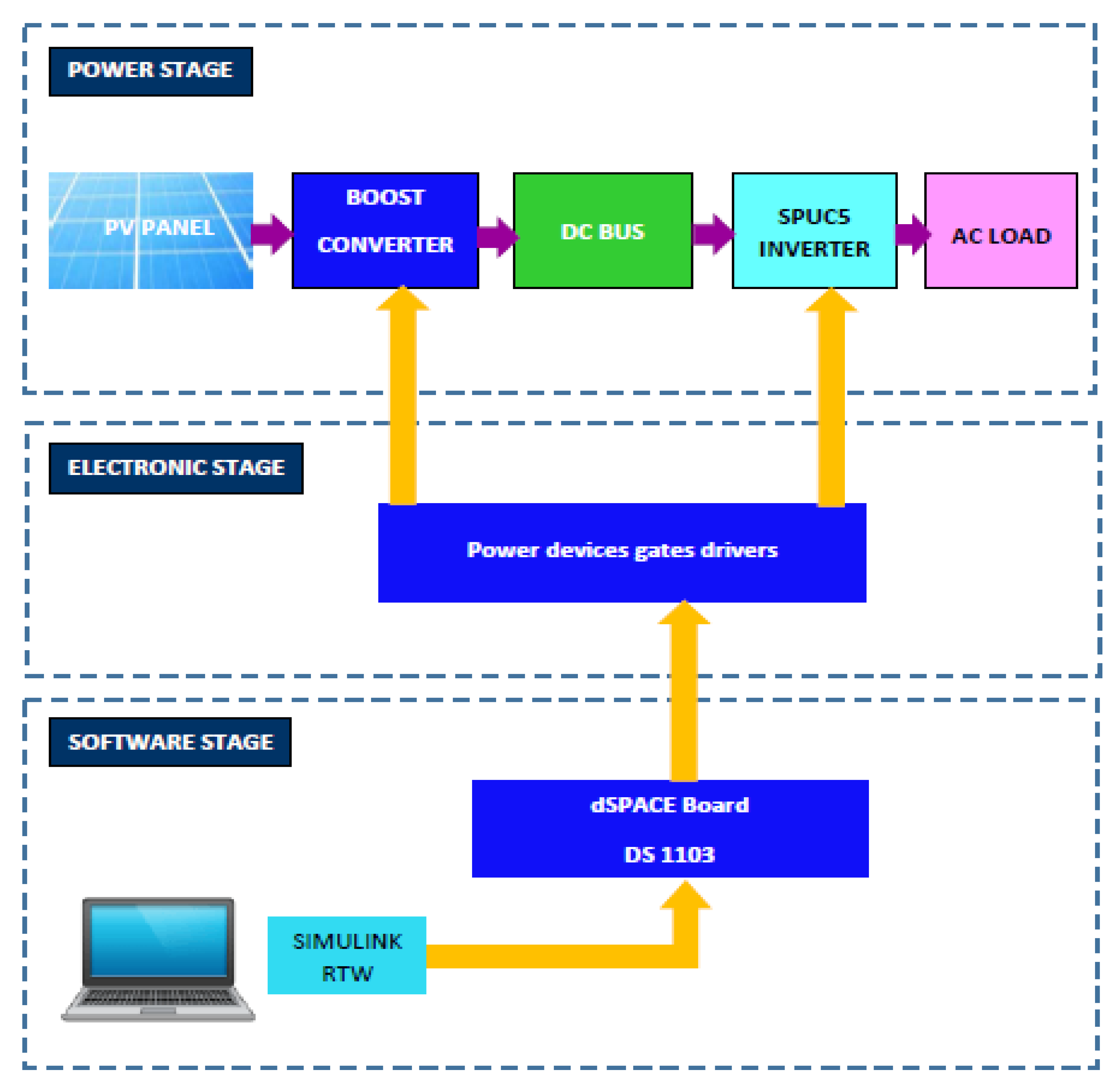
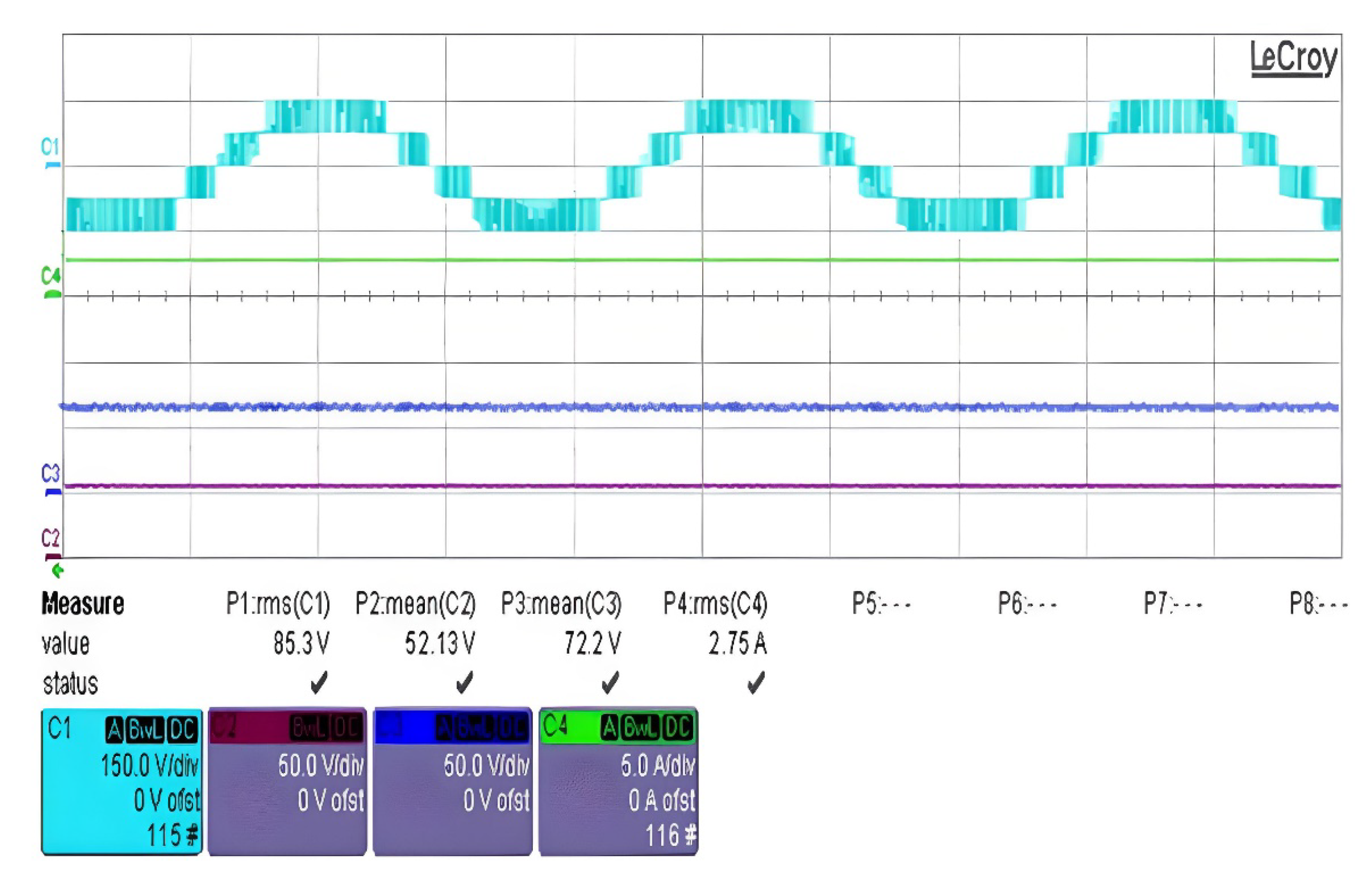
5. Experimental Validation

Experimental validation had been performed using the Dspace DS1103. Since no sensor or feedback is required for the SPUC5 inverter, hence, only five digital inputs/outputs are used to move the pulses out of the MOSFET gate. The MPPT technique, however, required an additional MOSFET and two sensors to acquire the PV array current and voltage. The experimental setup is depicted in Figure 14.
Figure 15 shows capacitances voltages which are well equilibrated about their reference, which is the half of the DC link voltage. These values are nearly the same as in Figure 7. The load current is nearly sinusoidal, whereas its values coincide with those in Figure 9. This offers the possibility to avoid using harmonics filters, which reduces the product cost. The output voltage of the inverter is also depicted in the same figure. The PV current and voltage evolution is shown in Figure 16. These values are in concordance with those of simulation, which validates the proposed concept experimentally.

6. Conclusions

A novel standalone PV system is presented in this paper. The incremental conductance has been preferred as the MPPT technique due to its high dynamics and rapidity in achieving the MPP, whereas, the SPUC5 has been proposed because it offers a high energetic efficiency conversion and it is well optimized in terms of component count. Moreover, the proposed PWM control technique allows for capacitor voltage balancing, without using any sensor or feedback, and ensures less THD rite compared to the traditional PWM method.
Simulation results have proven the high performance and the accuracy of the proposed system. Indeed, the tracking of the MPP was fast and very precise. Similarly, on the load side, the current waveform was almost sinusoidal due to the proposed PWM technique and the SPUC5 inverter. Therefore, there is no need to add filters, which reduces the product cost.
The experimental results ensure and validate the effectiveness of the advanced PWM used to control the SPUC5 inverter and all components and controls of the proposed PV system.

Author Contributions

Data curation, H.E.O.; Methodology, H.E.O.; Resources, H.E.O. and Y.O.; Software, H.E.O., A.E.G., Y.O. and K.A.-H.; Writing—original draft, H.E.O.; Writing—review and editing, Y.O. All authors have read and agreed to the published version of the manuscript.

Funding

This research was funded by l’école de technology supérieure, Montréal, Quebec, Canada.

Conflicts of Interest

The authors declare no conflict of interest.

References

  1. Awasthi, A.; Shukla, A.K.; Murali Manohar, S.R.; Dondariya, C.; Shukla, K.N.; Porwal, D.; Richhariya, G. Review on sun tracking technology in solar PV system. Energy Rep. 2020, 6, 392–405. [Google Scholar] [CrossRef]
  2. Jalil, M.F.; Khatoon, S.; Nasiruddin, I.; Bansal, R.C. Review of PV array modelling, configuration and MPPT techniques. Int. J. Model. Simul. 2022, 42, 533–550. [Google Scholar] [CrossRef]
  3. Ghamrawi, A.; Gaubert, J.P.; Mehdi, D. A new dual-mode maximum power point tracking algorithm based on the Perturb and Observe algorithm used on solar energy system. Sol. Energy 2018, 174, 508–514. [Google Scholar] [CrossRef]
  4. Kumar, V.; Singh, M. Derated mode of power generation in PV system using modified perturb and observe MPPT algorithm. J. Mod. Power Syst. Clean Energy 2020, 9, 1183–1192. [Google Scholar] [CrossRef]
  5. Pathak, P.K.; Padmanaban, S.; Yadav, A.K.; Alvi, P.A.; Khan, B. Modified incremental conductance MPPT algorithm for SPV-based grid-tied and stand-alone systems. IET Gener. Transm. Distrib. 2022, 16, 776–791. [Google Scholar] [CrossRef]
  6. Singh, P.; Shukla, N.; Gaur, P. Modified variable step incremental-conductance MPPT technique for photovoltaic system. Int. J. Inf. Technol. 2021, 13, 2483–2490. [Google Scholar] [CrossRef]
  7. Jately, V.; Azzopardi, B.; Joshi, J.; Venkateswaran V, B.; Sharma, A.; Arora, S. Experimental Analysis of hill-climbing MPPT algorithms under low irradiance levels. Renew. Sustain. Energy Rev. 2021, 150, 111467. [Google Scholar] [CrossRef]
  8. Baek, S.; Cho, Y.; Cho, B.G.; Hong, C. Performance comparison between two-level and three-level SiC-based VFD applications with output filters. IEEE Trans. Ind. Appl. 2019, 55, 4770–4779. [Google Scholar] [CrossRef]
  9. Vemuganti, H.P.; Sreenivasarao, D.; Ganjikunta, S.K.; Suryawanshi, H.M.; Abu-Rub, H. A survey on reduced switch count multilevel inverters. IEEE Open J. Ind. Electron. Soc. 2021, 2, 80–111. [Google Scholar] [CrossRef]
  10. Mondol, M.H.; Tür, M.R.; Biswas, S.P.; Hosain, M.K.; Shuvo, S.; Hossain, E. Compact three phase multilevel inverter for low and medium power photovoltaic systems. IEEE Access 2020, 8, 60824–60837. [Google Scholar] [CrossRef]
  11. Sridhar, V.; Umashankar, S.; Sanjeevikumar, P.; Ramachandaramurthy, V.K.; Mihet-Popa, L.; Fedák, V. Control architecture for cascaded H-bridge inverters in large-scale PV systems. Energy Procedia 2018, 145, 549–557. [Google Scholar] [CrossRef]
  12. Alepuz, S.; Busquets-Monge, S.; Nicolás-Apruzzese, J.; Filbà-Martínez, À.; Bordonau, J.; Yuan, X.; Kouro, S. A Survey on Capacitor Voltage Control in Neutral-Point-Clamped Multilevel Converters. Electronics 2022, 11, 527. [Google Scholar] [CrossRef]
  13. Ye, Y.; Hua, T.; Chen, S.; Wang, X. Neutral-Point-Clamped Five-Level Inverter with Self-Balanced Switched-Capacitor. IEEE Trans. Ind. Electron. 2021, 69, 2202–2215. [Google Scholar] [CrossRef]
  14. Zhao, X.; Jiang, D.; Chen, J.; Shen, Z.; Li, Q. Leakage current suppression with capacitor voltage control of three-level flying capacitor grid-connected inverters. IEEE Trans. Ind. Electron. 2021, 69, 2191–2201. [Google Scholar] [CrossRef]
  15. Humayun, M.; Khan, M.M.; Muhammad, A.; Xu, J.; Zhang, W. Evaluation of symmetric flying capacitor multilevel inverter for grid-connected application. Int. J. Electr. Power Energy Syst. 2020, 115, 105430. [Google Scholar] [CrossRef]
  16. Ounejjar, Y.; Al-Haddad, K.; Gregoire, L.A. Packed U cells multilevel converter topology: Theoretical study and experimental validation. IEEE Trans. Ind. Electron. 2010, 58, 1294–1306. [Google Scholar] [CrossRef]
  17. Al-Haddad, K.; Ounejjar, Y.; Gregoire, L.A. Multilevel Electric Power Converter. U.S. Patent No. 9,331,599, 3 May 2016. [Google Scholar]
  18. El Gadari, A.; El Ouardi, H.; Alibou, S.; Ounejjar, Y.; Bejjit, L.; Sharifzadeh, M.; Al-Haddad, K. New nine-level SPUC inverter using single DC source. In Proceedings of the 45th Annual Conference of the IEEE Industrial Electronics Society, Lisbon, Portugal, 14–17 October 2019; Volume 1, pp. 1892–1897. [Google Scholar]
  19. El Ouardi, H.; El Gadari, A.; Ounejjar, Y.; Kamal, A.H.; Alibou, S. A standalone photovoltaic system based on the SPUC5 inverter. In Proceedings of the IEEE 29th International Symposium on Industrial Electronics (ISIE), Delft, The Netherlands, 17–19 June 2020; pp. 1484–1489. [Google Scholar]
  20. El Ouardi, H.; El Kasmi Alaoui, M.; Nabaoui, M.; Habib, M.; El Gadari, A.; Ounejjar, Y.; Al-Haddad, K. Grid connected photovoltaic system based on SPUC5 inverter. In Proceedings of the 22nd IEEE International Conference on Industrial Technology (ICIT), Valencia, Spain, 10–12 March 2021; pp. 371–376. [Google Scholar]
  21. Serra, F.M.; Fernández, L.M.; Montoya, O.D.; Gil-González, W.; Hernández, J.C. Nonlinear voltage control for three-phase dc-ac converters in hybrid systems: An application of the pi-pbc method. Electronics 2020, 9, 847. [Google Scholar] [CrossRef]
  22. Jiménez-Castillo, G.; Muñoz-Rodríiguez, F.J.; Rus-Casas, C.; Hernández, J.C.; Tina, G.M. Monitoring PWM signals in stand-alone photovoltaic systems. Measurement 2019, 134, 412–425. [Google Scholar] [CrossRef]
  23. Rehman, H.U.; Yan, X.; Abdelbaky, M.A.; Jan, M.U.; Iqbal, S. An advanced virtual synchronous generator control technique for frequency regulation of grid-connected PV system. Int. J. Electr. Power Energy Syst. 2021, 125, 106440. [Google Scholar] [CrossRef]
Figure 1. The proposed SPUC5 inverter.
Electronics 11 02779 g001
Figure 2. The proposed control technique.
Electronics 11 02779 g002
Figure 3. A standard PV cell scheme.
Electronics 11 02779 g003
Figure 4. I-V and P-V characteristics of one SunPower SPR-305-WHT PV module.
Electronics 11 02779 g004
Figure 5. PV modules output power at constant irradiation.
Electronics 11 02779 g005
Figure 6. PV array output voltage at constant irradiation.
Electronics 11 02779 g006
Figure 7. DC-link voltage evolution (the green curve) and capacitors voltages evolution (the red and blue curves).
Electronics 11 02779 g007
Figure 8. Waveform of the load voltage.
Electronics 11 02779 g008
Figure 9. Waveform of the load current.
Electronics 11 02779 g009
Figure 10. The variation of irradiance.
Electronics 11 02779 g010
Figure 11. Waveform of the PV panel power under different levels of irradiation.
Electronics 11 02779 g011
Figure 12. Load current THD spectrum using the proposed method.
Electronics 11 02779 g012
Figure 13. Load current THD spectrum using the traditional PWM method.
Electronics 11 02779 g013
Figure 14. Experimental setup.
Electronics 11 02779 g014
Figure 15. Experimental waveforms showing: output voltage of the inverter (C1), load current (C4) and capacitors voltages (C2 and C3).
Electronics 11 02779 g015
Figure 16. Experimental waveforms showing: inverter output voltage (C1), PV array voltage (C2), capacitor voltage (C3) and PV array current (C4).
Electronics 11 02779 g016
Table 1. The switching states of the SPUC5 inverter.
DC Voltage CombinationSwitches Pulses
S1S2S3S4S5
E = VC1 + VC210010
VC110001
000110
−VC200101
−E = −VC1−VC201100
Table 2. The PV panel parameters.
ParametersValues
Maximum current Imax at Pmax (A)5.58
Maximum voltage Vmax at Pmax (V)54.7
Short circuit current Isc (A)5.96
Open circuit voltage Voc (V)64.2
Series resistance Rs (Ω)0.037998
Parallel resistance Rp (Ω)993.51
Number of cells96
Table 3. Simulation parameters.
ParametersValues
Fundamental frequency60 Hz
Switching frequency2000 Hz
SPUC5 capacitors4000 μF
Load resistor80 Ω
Load inductor15 mH
Publisher’s Note: MDPI stays neutral with regard to jurisdictional claims in published maps and institutional affiliations.

