Article

Broadband Ultra-Thin High-Efficiency Linear Polarizer Based on Metasurfaces

1
College of Safety Science and Engineering, Xi’an University of Science and Technology, Xi’an 710054, China
2
College of Communication and Information Engineering, Xi’an University of Science and Technology, Xi’an 710054, China
*
Author to whom correspondence should be addressed.
Electronics 2022, 11(16), 2599; https://doi.org/10.3390/electronics11162599
Submission received: 20 June 2022 / Revised: 17 July 2022 / Accepted: 18 July 2022 / Published: 19 August 2022
(This article belongs to the Section Electronic Materials)

Abstract

:
In this paper, an ultra-wideband (UWB) polarizer with high performance based on the metasurface is designed and demonstrated, which is composed of a dielectric substrate with a double-gap circular pattern and metal film. Multiple strong resonance points enable the design to achieve the conversion from incident linearly polarized waves to cross-polarized waves at 6.49–11.64 GHz, with a fractional bandwidth of 56.8% and a corresponding polarization conversion rate (PCR) of 90%. The PCR remains above 90% at 6.49–11.52 GHz when the electromagnetic wave is obliquely incident between 0° and 30°. Furthermore, the surface current distribution of the polarizer is discussed to explain the physical mechanism. The sample is fabricated for microwave validation. Compared with previous reports, the proposed polarizer has a larger bandwidth and higher efficiency and is expected to be used in microwave communications, antennas, radar cross section reduction, and other fields.

1. Introduction

Metamaterials (MMs), as artificially designed sub-wavelength materials, exhibit exotic characteristics compared with natural materials [1]. Over the past few decades, MMs have rapidly gained the attention of researchers owing to their unusual response to electromagnetic (EM) waves. The permittivity and permeability can be designed arbitrarily, which provides the possibility of using peculiar functional devices such as negative refraction [2], cloaks [3,4], holograms [5], images [6], perfect lenses [7], perfect absorption [8], sensors [9], and antennas [10]. The metasurface (MS) is a two-dimensional structure of the MMs. By designing the microstructure, the EM wave can be manipulated artificially. Among them, the control of EM wave polarization has aroused increasing interest [11,12,13,14,15,16,17,18]. However, the previously proposed MS devices suffer from narrow bandwidth and low efficiency, which limits their practical applications. To solve this problem, researchers have successively proposed a series of wideband high-efficiency polarization conversion devices [19,20,21]. For example, a transmissive-type anisotropic metadevice, consisting of stacks of bilayer gear-like metallic patterns, is proposed to manipulate the polarization state of electromagnetic waves. It can simultaneously achieve nondispersive cross-polarization conversion for both linearly and circularly polarized incident waves in a broadband frequency region. However, they are still generally limited due to the large device thickness. In recent years, researchers have proposed many ultrathin polarizers operating in the microwave band [22,23]. For example, an ultrathin linear-to-cross-polarization transmission MS converter [24] with a thickness of 0.8 mm (0.0235λ) was proposed that gives near-unity PCR at 8.8 GHz. Moreover, a tunable wideband reflective cross-polarization converter [25] with a T-shaped carved-hollow array based on the metasurface was designed, with a PCR greater than 80% and a fractional bandwidth of 40%. Similarly, a reflective broadband linear polarizer [26] composed of metallic disks and asymmetric arc metallic wires was presented, and its PCR value can be maintained over 90% in the range of 11.2–20.3 GHz when the incident angle varied from 0° to 40°. However, the operating bandwidth and efficiency need to be further improved. In addition, ultra-thin and wide-angle manipulated EM waves have also been extended to terahertz and near-infrared applications [27,28]. Therefore, the design of ultra-thin, UWB, and high-performance polarization devices still faces a series of challenges.
In this work, we propose an ultra-thin, UWB, and high-performance linear polarizer based on the MS. The thickness of the polarizer is only 3 mm (0.09λ). The device converts linearly polarized (LP) waves to orthogonally polarized waves. By decomposing the electric field, the working principle is explained. The surface current distribution at three response points is also detected to analyze the physical mechanism. The experimental results show that the PCR is higher than 90% within 6.49–11.64 GHz under the normal incidence of EM waves. When the oblique incidence angle is between 0° and 30°, the PCR can still reach 90% at 6.49–11.52 GHz. Since the proposed polarization device is ultra-thin and efficient, it is easier to integrate into other systems.

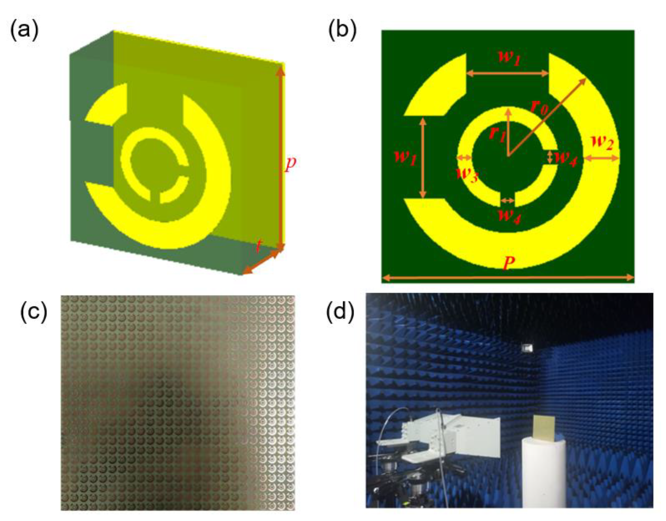
2. Design, Simulation, and Experiment

In general, the reflective polarizer has a multi-layer structure, including the top layer of MS, the intermediate layer, and the bottom metal film. The interference of the transmitted wave between the dielectric and metal layers forms the final reflected waves. Therefore, we can adjust the phase and amplitude of the reflected waves by adjusting the structure of the metal layer and the thickness of the dielectric layer.
We propose an ultra-broadband linear polarizer with high efficiency based on the design concept proposed above. The designed polarizer comprises three layers, as depicted in Figure 1a. A deformed double-gap circular metal pattern makes up the top layer of this structure. The intermediate substrate layer is FR-4 with a relative permittivity of 4.3 and a loss tangent of 0.025. A metal film forms the bottom layer to block EM waves. The metal layers are copper with a conductivity of 5.8 × 10⁷ S/m and a thickness of 0.035 mm. The front view of the polarizer is depicted in Figure 1b. The optimized geometries of the polarizer displayed in Figure 1a are: r0 = 3.1 mm, r1 = 1.4 mm, t = 3 mm, p = 7 mm, w1 = 2.3 mm, w2 = 1.0 mm, w3 = 0.4 mm, and w4 = 0.1 mm. Figure 1c shows a photograph of the partially fabricated sample, and Figure 1d presents the experimental environment and setup.
To study the EM response of this polarizer, we simulate the designed MS using CST 2019. The infinite model structure is numerically analyzed by setting the Floquet boundary on the x and y axes. In order to better understand the UWB polarizer, for x-polarized incident waves, we define r x x = | E x r / E x i | and r y x = | E y r / E x i | as the reflectance of the co-polarization and cross-polarization, respectively. The corresponding subscripts i and r indicate the incident and reflected EM waves, respectively. Here, the PCR and polarization extinction ratio (PER) are utilized to describe the polarization conversion performance and the polarization stability of the polarizer, respectively. The PCR and PER are defined as [29]:
P C R x = | r y x | 2 / ( | r y x | 2 + | r x x | 2 ) ,
P E R = 10 lg ( | r y x | 2 / | r x x | 2 ) ,

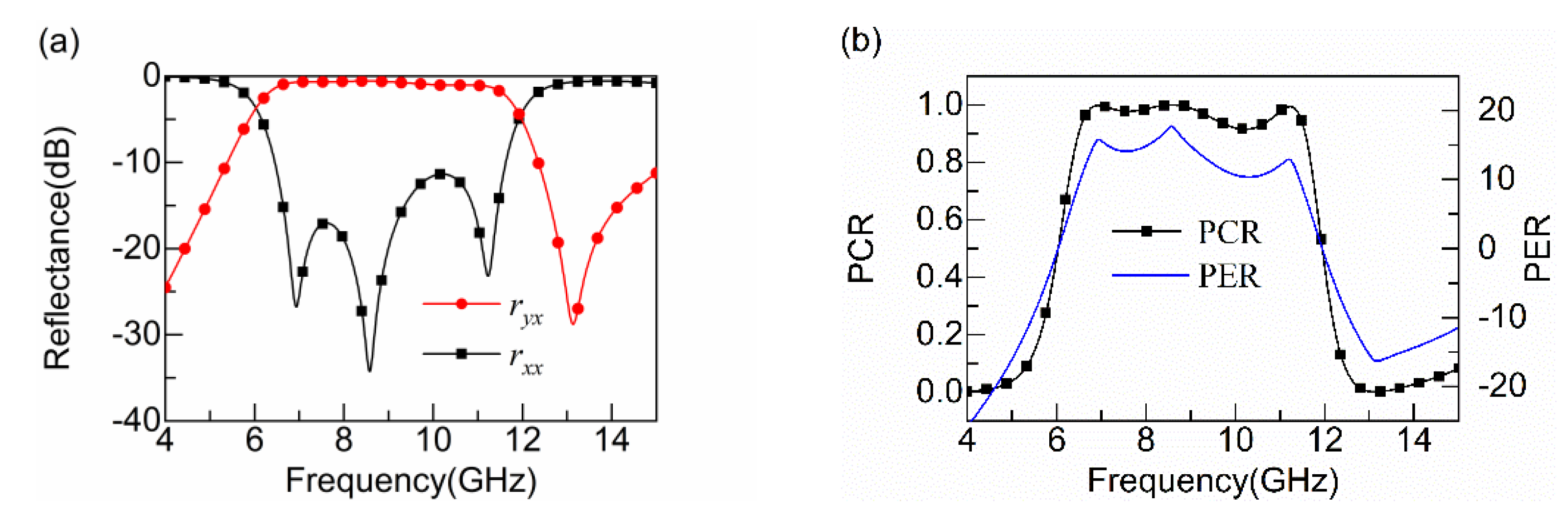
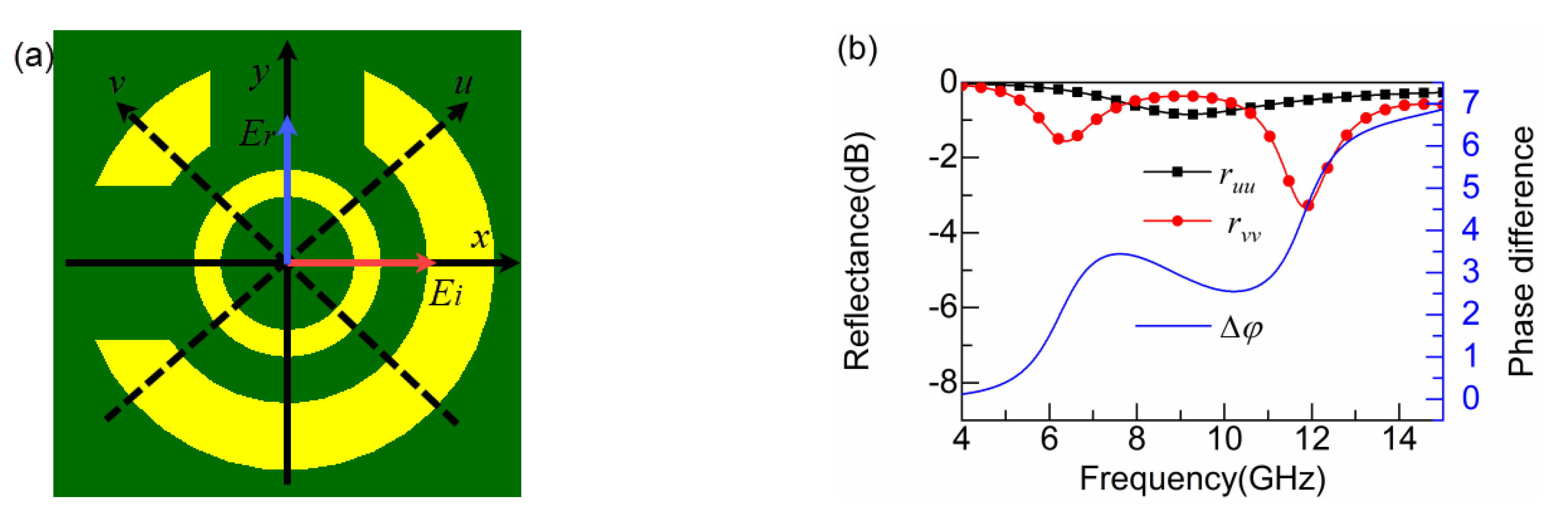
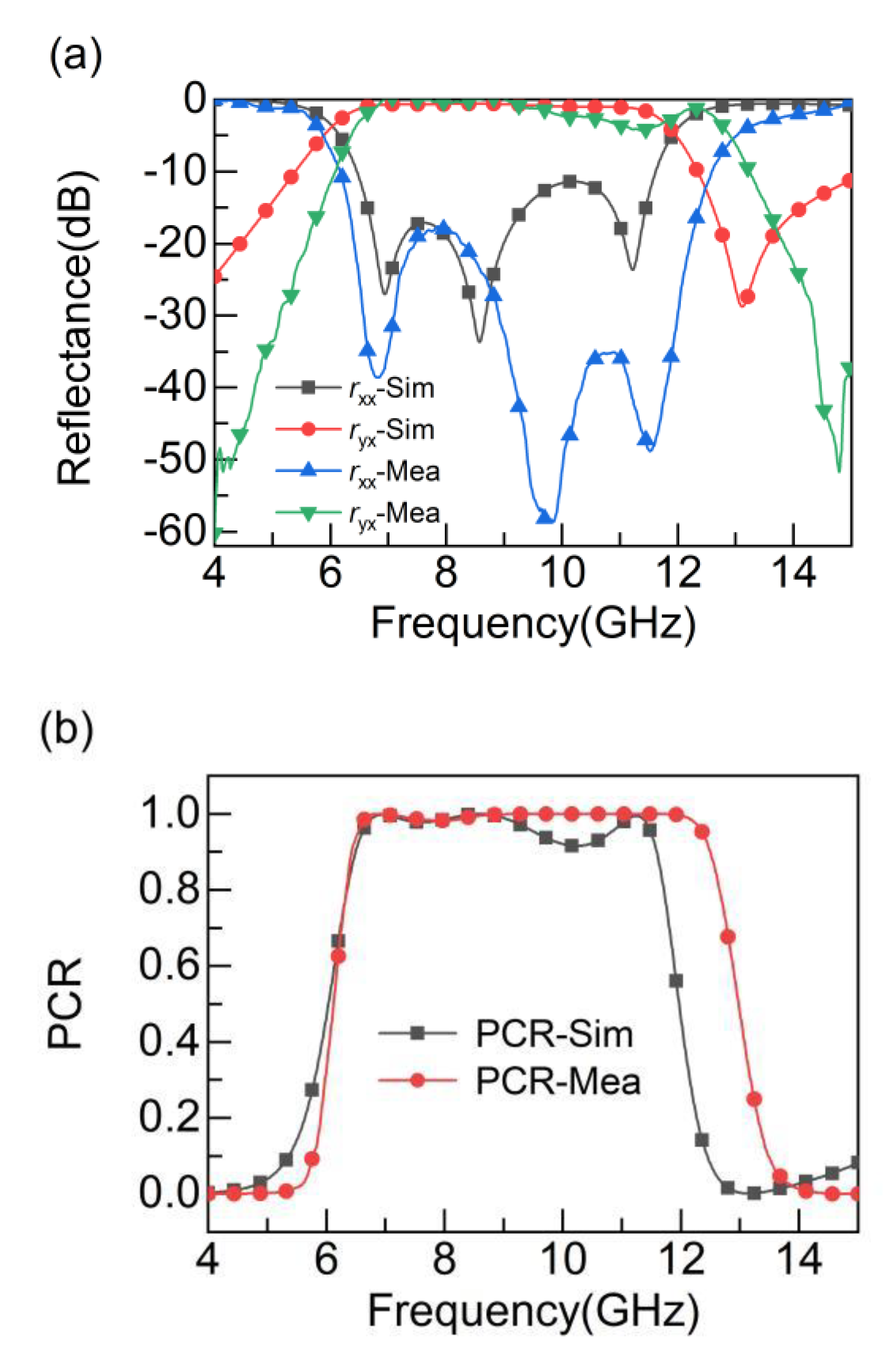
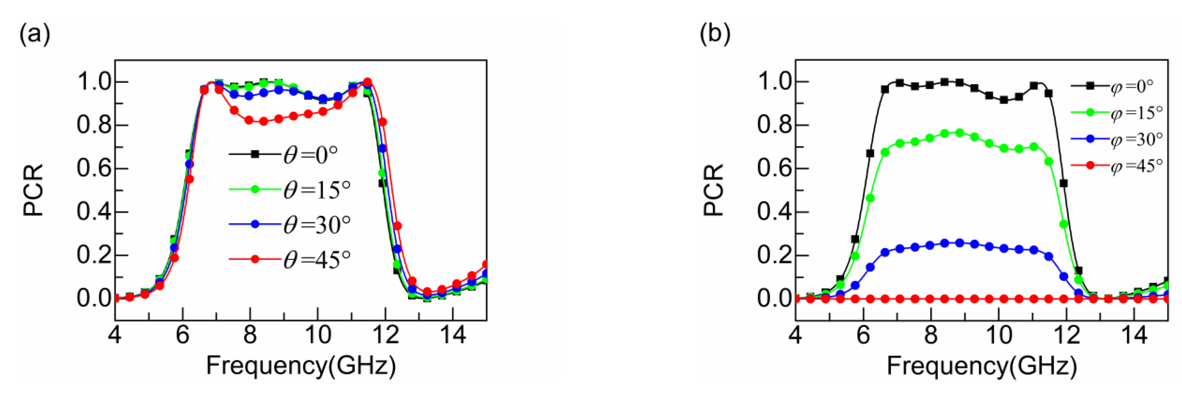
3. Results and Discussion

First of all, we investigate the cross-polarization conversion performance under x-polarized incident waves. Figure 2a,b show the simulated reflectance and the corresponding PCR and PER, respectively. We can clearly see that the simulated ryx is above −1 dB at 6.60–11.22 GHz, and the corresponding rxx is below −10 dB, with a relative bandwidth of 53.2%. In addition, the reflected waves resonate strongly at 6.93 GHz, 8.57 GHz, and 11.23 GHz, corresponding to a PCR of 100%. The presence of resonance points explains cross-polarization conversion, while more resonance points leads to a larger conversion bandwidth. Figure 2b indicates that the calculated PCR is greater than 90% within 6.49–11.64 GHz. Meanwhile, the PER can reach 15.2 dB, 17.9 dB, and 14.8 dB at the three resonance points, respectively. The above results prove that the designed polarizer can efficiently transform LP waves into their orthogonal polarized counterparts in the broadband range.
Assuming that the incident EM waves (Ei) propagate along the x axis, the reflected waves will propagate along the y axis. The electric field can be decomposed along the u and v directions. The u-v axis is derived by turning the x-y axis 45° counterclockwise. Figure 3a shows a schematic diagram of the electric field decomposition. Therefore, the incident and reflected electric fields can be expressed as [30]:
E i = x E 0 = u E i u e j ϕ + v E i v e j ϕ
E r = u r u u E i u e j ( ϕ + ϕ u u ) + v r v v E i v e j ( ϕ + ϕ v v ) ,
where ruu and rvv represent the reflectance of the u axis and v axis, respectively, and ϕuu and ϕvv stand for the reflection phase of the u axis and v axis, respectively. The converter can exhibit anisotropic properties attributed to the asymmetry of the structure. When ruu = rvv = 1 and Δφ = ϕuu − ϕvv = 180° are satisfied, the complex electric field of the reflected waves (Er) is located along the y axis, indicating that the polarization orientation of the reflected wave is converted to the orthogonal orientation of the incident wave. Consequently, for x-polarized incident waves, Formula (4) can be further stated as:
E r = u r u u E i u e j ( ϕ + ϕ u u ) + v r v v E i v e j ( ϕ + ϕ u u π ) = ( u E i u v E i v ) e j ( ϕ + ϕ u u ) = y E 0 e j ( ϕ + ϕ u u )
According to Figure 3b, we can observe that co-polarized reflection amplitudes (ruu, rvv) are almost equal and close to 1, while the corresponding phase difference is 180° in the operating frequency range. This indicates that the polarizer achieves the conversion from x-polarized incident waves to y-polarized reflected waves.
The surface current distributions are monitored at 6.93 GHz, 8.57 GHz, and 11.23 GHz resonance points to explain the physical mechanism of the polarizer. Figure 4a,c exhibit the current distributions at 6.93 GHz and 11.23 GHz for the top and bottom layers, respectively. We note that the current distributions in the top and bottom metal layers are reversed, and a current loop is formed in the middle dielectric layer to excite the magnetic dipoles. For x-polarized incident waves (the electric field E is along the x direction and the magnetic field H is along the y direction), the magnetic field H0 excited by a magnetic dipole can be decomposed into a set of orthogonal magnetic field components Hx and Hy. Hy along the y direction is parallel to the original magnetic field H, and Hx along the x direction is orthogonal to H. This allows the x-polarized incident waves to be transformed into its orthogonal y-polarized waves. Figure 4b demonstrates the surface current distributions at 8.57 GHz. Different from the previous physical mechanism, electric resonance is the leading cause of polarization conversion, and the analysis is the same as above. In summary, interaction between surface currents generates magnetic resonance (electrical resonance). A component of the induced magnetic field H0 (induced electric field E0) is perpendicular to the original magnetic field (electric field), thus converting the incident LP waves into the orthogonally polarized waves. Simultaneously, the multiple resonances extend the bandwidth.
To validate our proposed linear polarization converter, a sample of 25 × 25 cells with dimensions of 175 mm × 175 mm is fabricated. The reflectance of the fabricated polarizer is measured in an anechoic chamber using an analyzer (R&S ZNB/40) connected to two standard gain horn antennas. It should be noted that the sample should be placed vertically, and the angle between the two horn antennas should be within 5° [31]. A horn antenna is placed horizontally to emit x-polarized EM waves. Another horn antenna is placed horizontally and vertically to measure the co-polarized and cross-polarized reflectance (rxx and ryx), respectively.
A comparison of the simulated and measured results is given in Figure 5. According to the measured reflectance rxx, we can observe that the three resonant frequencies (at 6.85 GHz, 9.84 GHz, and 11.52 GHz) are below −20 dB at 6.04–12.23 GHz. Furthermore, the cross-polarized reflectance ryx is approximately consistent with the simulated curve in such a frequency range. Similarly, we can view that the PCR calculated from the measured reflectance (rxx, ryx) largely coincides with the PCR calculated from the simulations. The measurement error can be attributed to the following two aspects. Firstly, an infinite plane is simulated in the CST; however, the actual measured sample is finite, which leads to edge diffraction effects. Secondly, the dielectric constant of the substrate in the processed sample is slightly different from the simulated model. Therefore, the stated reasons lead to a discrepancy between the simulated and experimental results.

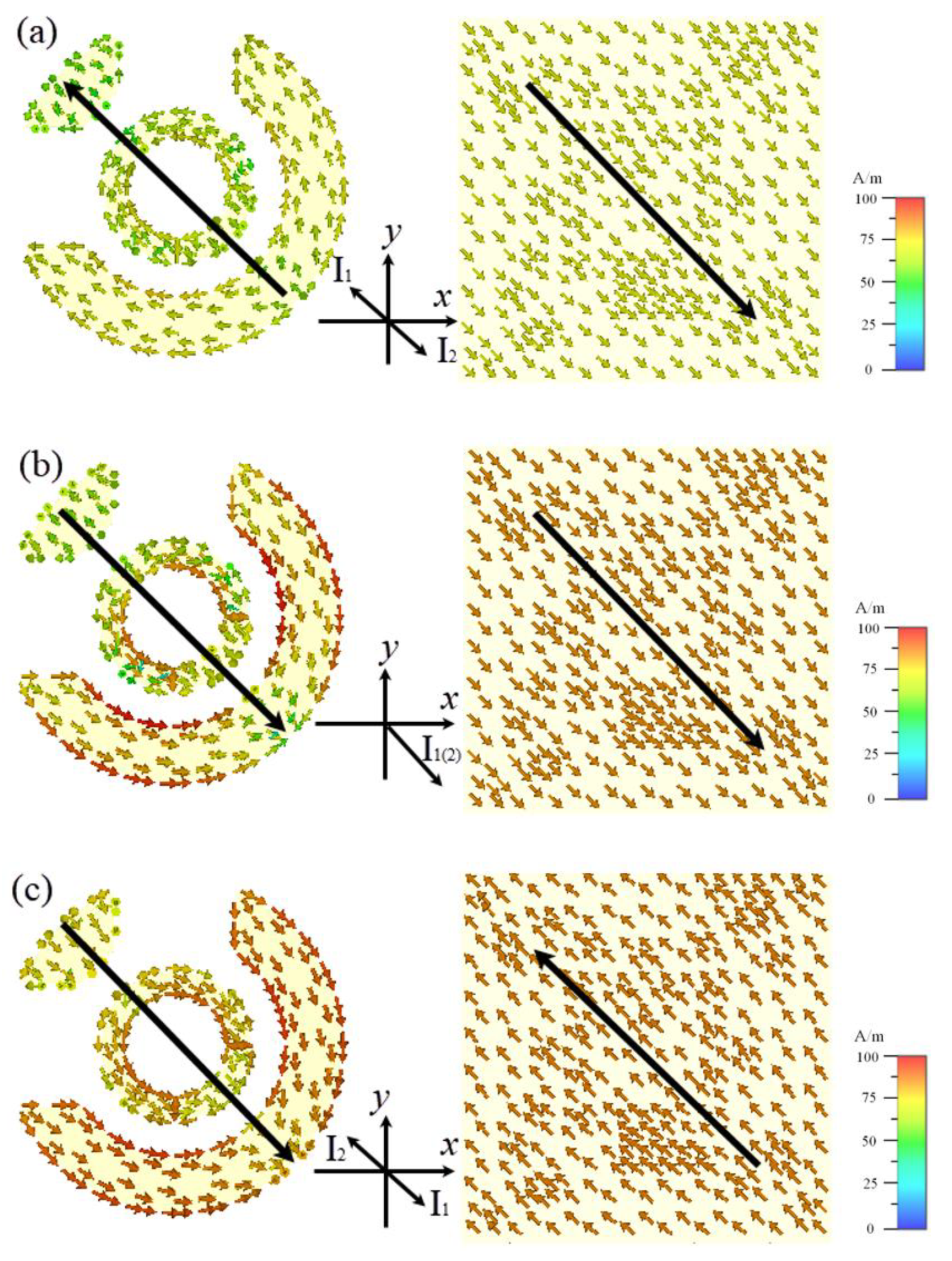
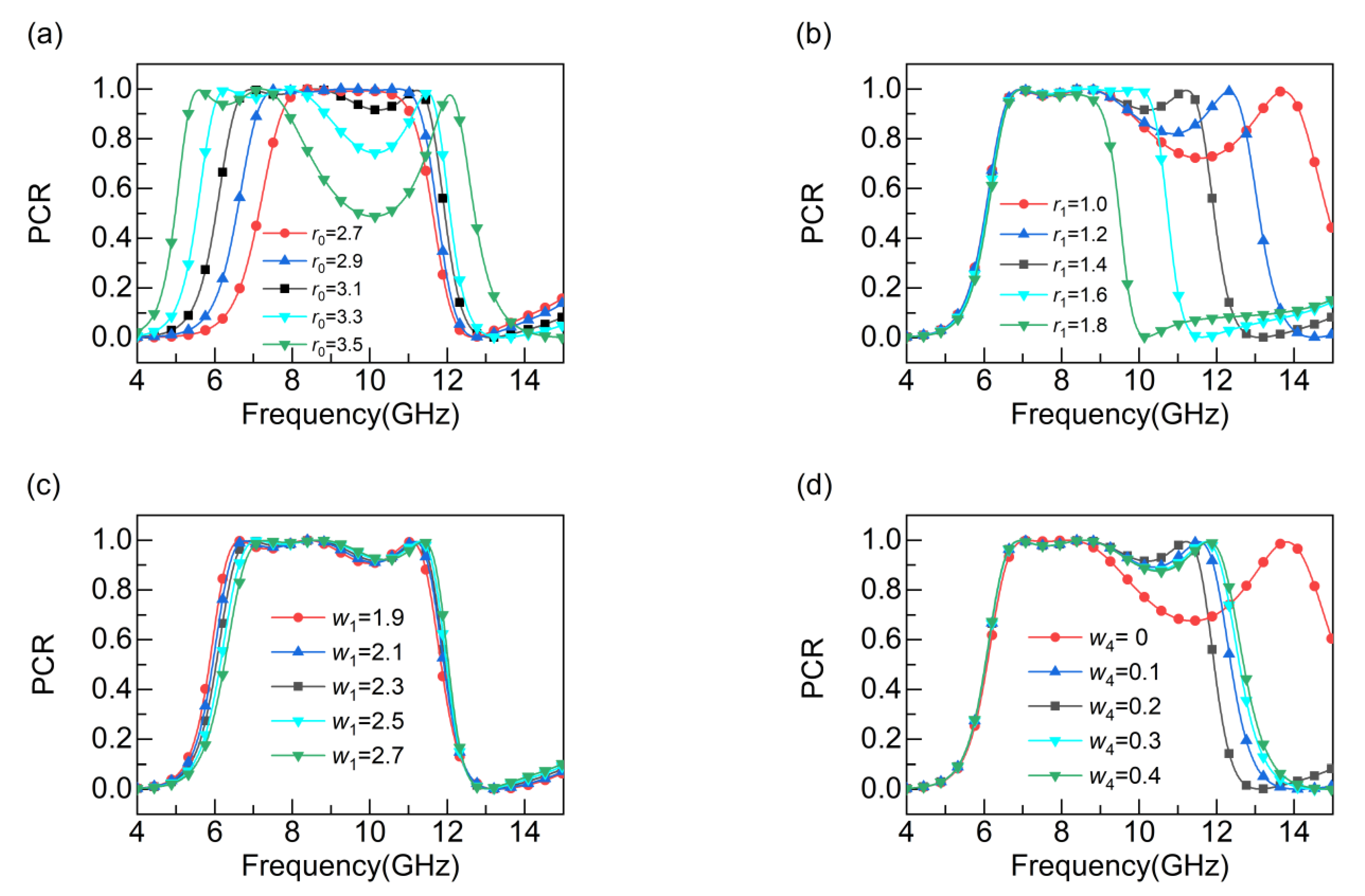
4. Parameter Analysis

Parameter analysis is then performed to reveal the geometric influence of the designed broadband metasurface. Figure 6a shows that the bandwidth of the polarization conversion grows gradually as the radius of the outer ring r0 increases, and the PCR decreases sharply when r0 exceeds 3.1 mm. However, with an increase in the inner ring radius r1, the bandwidth of polarization conversion progressively becomes narrower, as indicated in Figure 6b. A change in the outer ring radius r0 and inner ring radius r1 affects the inductive and capacitive effects in the u-v direction, resulting in a change in the corresponding polarization phase, thus affecting the performance of polarization conversion. Next, we focus on the effect of the opening slit on PCR, as depicted in Figure 6c,d, where the PCR remains almost unchanged with an increasing slit width for both the outer and inner ring slits. The outer and inner ring slits w1 and w4 are located in the horizontal and vertical directions, respectively, and the decomposed components along the u-v direction are unchanged, so they have little effect on the polarization conversion performance. Moreover, we can also explore the impact of different incident angles and polarization angles on conversion efficiency, as shown in Figure 7. From Figure 7a, the PCR exceeds 90% in the range of 6.49–11.64 GHz when the oblique incidence angle is 0°–30°, and the PCR decreases with an increase in the polarization angle, as displayed in Figure 7b. This is primarily due to the fact that the designed polarizer is not centrosymmetric. From the foregoing analysis, we can conclude that the polarizer shows good conversion performance after selecting the appropriate geometric parameters. Finally, Table 1 gives a performance comparison between the proposed polarizer in this paper and the previous works.

5. Conclusions

To summarize, we propose an ultra-thin, UWB, and high-efficiency linear polarizer. The thickness of the polarizer is only 3 mm (0.09λ). The UWB of the polarizer is derived from three EM resonances. Numerical analysis and measured results show that the PCR is greater than 90% at 6.49–11.64 GHz, and the corresponding fractional bandwidth reaches 56.8%. Moreover, the PCR is higher than 90% in the range of 6.49–11.52 GHz when the oblique incidence angle is 0°–30°. Finally, the physical mechanism of the polarizer is analyzed and the effect of geometric parameters on PCR is investigated. The converter designed in this paper can be applied in wireless communication and RCS reduction.

Author Contributions

Conceptualization, P.L.; methodology, P.L.; software, J.H.; validation, Y.W.; formal analysis, P.L.; investigation, Y.W. and J.H.; data curation, Y.W.; writing—original draft preparation, Y.W. and J.H.; writing—review and editing, X.H.; supervision, X.H. All authors have read and agreed to the published version of the manuscript.

Funding

This work was supported by the Project of Science and Technology of Shaanxi (2021JM-395).

Conflicts of Interest

The authors declare no conflict of interest.

References

  1. Shelby, A.R.A.; Smith, D.R.; Schultz, S. Experimental verification of a negative index of refraction index of refraction. Science 2001, 292, 77–79. [Google Scholar] [CrossRef] [PubMed]
  2. Smith, D.R.; Pendry, J.B.; Wiltshire, M.C.K. Metamaterials and negative refractive index. Science 2004, 305, 788–792. [Google Scholar] [CrossRef] [PubMed]
  3. Schuring, D.; Mock, J.J.; Justice, B.J.; Cummer, S.A.; Pendry, J.B.; Starr, A.F.; Smith, D.R. Metamaterial electromagnetic cloak at microwave frequencies. Science 2006, 314, 977–980. [Google Scholar] [CrossRef] [PubMed]
  4. Liu, S.; Xu, H.-X.; Zhang, H.C.; Cui, T.J. Tunable ultrathin mantle cloak via varactor-diode-loaded metasurface. Opt. Express 2014, 22, 13403. [Google Scholar] [CrossRef]
  5. Zheng, J.; Ye, Z.; Sun, N.; Zhang, R.; Sheng, Z.; Shieh, H.D.; Zhang, J. Highly anisotropic metasurface: A polarized beam splitter and hologram. Sci. Rep. 2014, 4, 6491. [Google Scholar] [CrossRef]
  6. Chen, W.T.; Yang, K.Y.; Wang, C.M.; Huang, Y.W.; Sun, G.; Chiang, I.D.; Liao, C.Y.; Hsu, W.L.; Lin, H.T.; Sun, S. High-efficiency broadband meta-hologram with polarization-controlled dual images. Nano Lett. 2014, 14, 225–230. [Google Scholar] [CrossRef]
  7. Pendry, J.B. Negative refraction makes a perfect lens. Phys. Rev. Lett. 2000, 85, 3966–3969. [Google Scholar] [CrossRef]
  8. Landy, N.I.; Sajuyigbe, S.; Mock, J.J.; Smith, D.R.; Padilla, W.J. Perfect metamaterial absorber. Phys. Rev. Lett. 2008, 100, 207402. [Google Scholar] [CrossRef]
  9. Shokati, E.; Asgari, S.; Granpayeh, N. Dual-band polarization-sensitive graphene chiral metasurface and its application as a refractive index sensor. IEEE Sens. J. 2019, 19, 9991–9996. [Google Scholar] [CrossRef]
  10. Pan, S.; Caster, F.; Heydari, P.; Member, S.; Capolino, F. A 94-GHz extremely thin metasurface-based. IEEE Trans. Antennas Propag. 2014, 62, 4439–4451. [Google Scholar] [CrossRef]
  11. Huang, X.; Yang, D.; Yang, H. Multiple-band reflective polarization converter using U-shaped metamaterial. J. Appl. Phys. 2014, 115, 13–19. [Google Scholar] [CrossRef]
  12. Wang, Z.; Cheng, F.; Winsor, T.; Liu, Y. Optical chiral metamaterials: A review of the fundamentals, fabrication methods and applications. Nanotechnology 2016, 27, 421001. [Google Scholar] [CrossRef] [PubMed]
  13. Ding, F.; Pors, A.; Bozhevolnyi, S.I. Gradient metasurfaces: A review of fundamentals and applications. Rep. Prog. Phys. 2018, 81, 026401. [Google Scholar] [CrossRef] [PubMed]
  14. Shi, H.; Zhang, A.; Zheng, S.; Li, J.; Jiang, Y. Dual-band polarization angle independent 90° polarization rotator using twisted electric-field-coupled resonators. Appl. Phys. Lett. 2014, 104, 034102. [Google Scholar]
  15. Cheng, Y.Z.; Nie, Y.; Cheng, Z.Z.; Wang, X.; Gong, R.Z. Asymmetric chiral metamaterial circular polarizer based on twisted split-ring resonator. Appl. Phys. B Lasers Opt. 2014, 116, 129–134. [Google Scholar] [CrossRef]
  16. Liu, D.; Xiao, Z.; Ma, X.; Wang, L.; Xu, K.; Tang, J.; Wang, Z. Dual-band asymmetric transmission of chiral metamaterial based on complementary U-S=shaped structure. Appl. Phys. A Mater. Sci. Proc. 2015, 118, 787–791. [Google Scholar] [CrossRef]
  17. Zhou, Z.; Yang, H. Triple-band asymmetric transmission of linear polarization with deformed S-shape bilayer chiral metamaterial. Appl. Phys. A Mater. Sci. Proc. 2015, 119, 115–119. [Google Scholar] [CrossRef]
  18. Naseri, P.; Costa, J.R.; Matos, S.A.; Fernandes, C.A.; Hum, S.V. Equivalent circuit modeling to design a dual-band dual linear-to-circular polarizer surface. IEEE Trans. Antennas Propag. 2020, 68, 5730–5735. [Google Scholar] [CrossRef]
  19. Huang, X.; Chen, J.; Yang, H. High-efficiency wideband reflection polarization conversion metasurface for circularly polarized waves. J. Appl. Phys. 2017, 122, 043102. [Google Scholar] [CrossRef]
  20. Song, K.; Su, Z.; Silva, S.; Fowler, C.; Ding, C.; Ji, R.; Liu, Y.; Zhao, X.; Zhou, J. Broadband and high-efficiency transmissive-type nondispersive polarization conversion meta-Device. Opt. Mater. Express 2018, 8, 2430–2438. [Google Scholar] [CrossRef]
  21. Li, F.; Chen, H.; Zhang, L.; Zhou, Y.; Xie, J.; Deng, L.; Harris, V.G. Compact high-efficiency broadband metamaterial polarizing reflector at microwave frequencies. IEEE Trans. Microw. Theory Tech. 2019, 67, 606–614. [Google Scholar] [CrossRef]
  22. Xu, J.; Li, R.; Qin, L.; Wang, S.; Han, T. Ultra-broadband wide-angle linear polarization converter based on H-shaped metasurface. Opt. Express 2018, 26, 20913–20919. [Google Scholar] [CrossRef] [PubMed]
  23. Liu, C.; Gao, R.; Wang, Q.; Liu, S. A design of ultra-wideband linear cross-polarization conversion metasurface with high efficiency and ultra-thin thickness. J. Appl. Phys. 2020, 127, 5143831. [Google Scholar] [CrossRef]
  24. Baghel, A.K.; Kulkarni, S.S.; Nayak, S.K. Linear-to-cross-polarization transmission converter using ultrathin and smaller periodicity metasurface. IEEE Antennas Wirel. Propag. Lett. 2019, 18, 1433–1437. [Google Scholar] [CrossRef]
  25. Qiao, Q.; Liu, Y.; Yang, X.; Fu, Y.; Zhou, X.; Li, R.; Lu, M.; Wang, Y. Tunable broadband crosspolarization converter based on a graphene sheet with a T-Shaped carved-hollow array. J. Opt. Soc. Am. B 2021, 38, 1748–1755. [Google Scholar] [CrossRef]
  26. Wang, Q.; Kong, X.; Yan, X.; Xu, Y.; Liu, S.; Mo, J.; Liu, X. Flexible broadband polarization converter based on metasurface at microwave band. Chinese Phys. B 2019, 28, 074205. [Google Scholar] [CrossRef]
  27. Li, P.; Hu, G.; Dolado, I.; Tymchenko, M.; Qiu, C.; Alfaro-mozaz, F.J.; Casanova, F.; Hueso, L.E.; Liu, S.; Edgar, J.H. Collective near-field coupling and nonlocal phenomena in infrared-phononic metasurfaces for nano-light canalization. Nat. Commun. 2020, 11, 3663. [Google Scholar] [CrossRef]
  28. Zou, M.; Su, M.; Yu, H. Ultra-broadband and wide-angle Terahertz polarization converter based on symmetrical anchor-shaped metamaterial. Opt. Mater. 2020, 107, 110062. [Google Scholar] [CrossRef]
  29. Khan, M.I.; Fraz, Q.; Tahir, F.A. Ultra-wideband cross polarization conversion metasurface insensitive to incidence angle. J. Appl. Phys. 2017, 121, 045103. [Google Scholar] [CrossRef]
  30. Xu, J.; Li, R.; Wang, S.; Han, T. Ultra-broadband linear polarization converter based on anisotropic metasurface. Opt. Express 2018, 26, 26235–26241. [Google Scholar] [CrossRef]
  31. Wang, H.B.; Cheng, Y.J.; Member, S.; Chen, Z.N. Wideband and wide-angle single-layered-substrate linear-to-circular polarization metasurface converter. IEEE Trans. Antennas Propag. 2019, 68, 1186–1191. [Google Scholar] [CrossRef]
  32. Shi, H.; Li, J.; Zhang, A.; Wang, J.; Xu, Z. Broadband cross polarization converter using plasmon hybridizations in a ring/disk cavity. Opt. Express 2014, 22, 20973. [Google Scholar] [CrossRef] [PubMed]
  33. Nguyen, T.K.T.; Nguyen, T.M.; Nguyen, H.Q.; Cao, T.N.; Le, D.T.; Bui, X.K.; Bui, S.T.; Truong, C.L.; Vu, D.L.; Nguyen, T.Q.H. Simple design of efficient broadband multifunctional polarization converter for X-band applications. Sci. Rep. 2021, 11, 2032. [Google Scholar] [CrossRef] [PubMed]
Figure 1. (a) Three-dimensional view of the polarizer; (b) front view of the polarizer; (c) photo of the experimental samples (25 × 25 cells with dimensions of 175 mm × 175 mm); (d) measurement environment photo.
Electronics 11 02599 g001
Figure 2. Simulated results (a) reflectance; (b) PCR and PER.
Electronics 11 02599 g002
Figure 3. (a) Electric field decomposition diagram; (b) reflectance and phase difference in the u, v direction.
Electronics 11 02599 g003
Figure 4. Surface current distribution (a) 15.45 GHz; (b) 20.82 GHz; (c) 26.94 GHz.
Electronics 11 02599 g004
Figure 5. Simulated and measured results of x-polarized incidence. (a) Reflectance; (b) PCR.
Electronics 11 02599 g005
Figure 6. PCR with different parameters (a) r0; (b) r1; (c) w1; (d) w4.
Electronics 11 02599 g006
Figure 7. PCR with (a) a different incident angle; (b) a different polarization angle.
Electronics 11 02599 g007
Table 1. Performance comparison with previous works.
PaperFrequency RangeFractional BandwidthPCR
[24]8.8 GHz/1
[32]9.65–14.16 GHz38%80%
[25]10.29–15.46 THz40%80%
[33]8–12 GHz40%90%
[26]11.3–20.2 GHz53.4%85%
This work6.49–11.5256.8%90%
Publisher’s Note: MDPI stays neutral with regard to jurisdictional claims in published maps and institutional affiliations.

