1. Introduction
The goal of the video frame interpolation (VFI) method is to generate a frame between two temporally continuous video frames of a given input frame. With the development of over-the-top media (OTT) services and Internet TV, video still accounts for a large portion of the overall network. Accordingly, the demand for technologies such as video compression using VFI technology and frame rate upsampling of past content is increasing. Recently, with the advent of the convolutional neural network (CNN), the spatial processing of the convolutional kernel using deep learning has improved dramatically, and new solutions through deep learning are emerging in various classical image fields. However, the method using deep learning has not been actively utilized in the field of VFI.
The VFI method through deep learning has various difficulties that do not exist in other fields. The field of VFI is a generally ill-posed problem. Since video is light reflected from real three-dimensional objects and projected on a 2 dimension Charge-Coupled Device (CCD) plane, it is impossible to accurately measure the shape and distance of a real object due to the application of the point diffusion function (PSF) [
1] in the real world. Therefore, in a video without depth information, it is only possible to estimate which object will be revealed or concealed at which time point
t of the two moving objects.
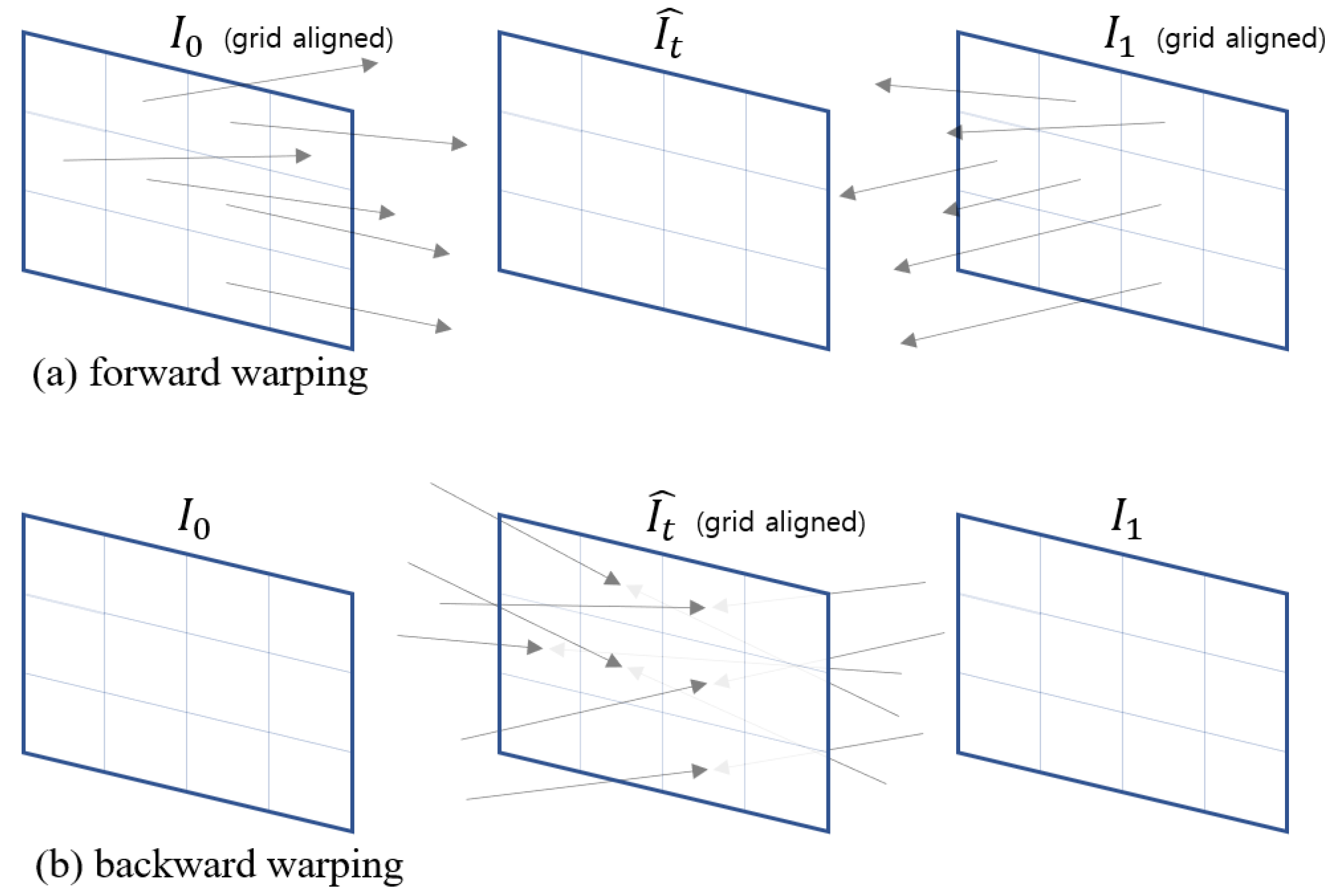
Our main idea is as follows. After estimating the motion of the input image with the optical flow, the t-point image candidate of the object is generated through forward warping. When two moving objects intersect, one object is revealed or concealed. Therefore, it is necessary to have a deep network choose the contextual scene of the object’s contextual relationship. Almost all traditional VFI methods use the backward warning method to generate interpolation frames (from pytorch implemented as torch.nn.functional.grid_sample() function). Using this method, interpolated frames, as shown in
Figure 1b, are grid-aligned with pixels, resulting in no hole or occlusion area, which is easy to implement but causes incorrect mixing of movements. In order for the backward warping function to work properly, the condition that the interpolation result flow does not overlap and must be invertable [
2].
In this paper, since the backward warping process is replaced by the forward warping process, hole and occlusion problems will occur when generating the interpolated image. Therefore, we use forward max-warping and forward min-warping to handle occlusion regions, where we interpolate the image by adopting the largest pixel of the motion vector during forward warping or by adopting the smallest pixel. In the subsequent deep network, it is designed to adopt the interpolation result suitable for the context among the interpolation, max-warping result, and the min-warping result of the hole region.
Finally, the spatial receptive field can be reduced through the proposed max-min warping so that the network can understand the domain at a deeper level. Because the proposed forward warping method uses U-Net and max-min warping, a clearer warping performance can be expected than the previous backward warping method, and since the output of the network is an RGB image rather than a flow map, it is more free from morphological inference.
Because the proposed method uses U-Net and max-min warping, a clearer warping performance can be expected than the previous method using backward warping, and it is a network that allows the network to select the warping image afterward so that the morphological inference of the output is possible.
The contribution of our research is as follows: First, we propose max-min warping that can replace the existing backward warping method. Second, by using the existing flow encoder to reduce the spatio-temporal encoder burden, it allows the network to select the warping result, so it has an output with a high degree of freedom. Third, it was shown that warping performance and PSNR can be improved by using an edge-aware smoothing filter through domain transformation in a flow map.
The structure of this paper is as follows.
Section 2 introduces the research related to the VFI method, and
Section 3 describes the proposed network and warping methods.
Section 4 evaluated the objective and subjective performance through experiments and showed whether the proposed network can understand and use the input warping image.
2. Related Works
The VFI method is self-supervised learning using the middle frame of the video sequence as the target image. Most studies of VFI use a method of estimating the optical flow first and then warping the input image based on the estimated flow to preserve frame uniformity. Conventional VFI methods that are not estimated flows are as follows. The classic method of VFI. In the phase-based interpolation method [
3], two input images are transformed from the spatial domain to frequency space and interpolated. It uses a wavelet transform to linearly interpolate the coefficients of the input frame to generate an intermediate image. Although this method showed interpolation image improvement through relatively few calculations, it has a disadvantage in that it cannot predict large motions or morphological changes of objects. In [
4], bidirectional motion prediction through the block matching algorithm (BMA) and the interpolation of intermediate frames through motion are refined. BMA has less computational complexity and generates interpolated images with the least flickering, so it is a practical study applicable to actual products.
In deep learning-based VFI, the initial deep learning-based research that started with the use of CNN networks can be called [
5]. In adaconv, after going through several stages of a CNN network called ConvNet, two consecutive input images create a network that generates a convolutional kernel K through supervised learning. Since an interpolated image is generated through convolution with the input with this kernel, morphologically various outputs are possible, unlike image generation that only uses linear interpolation through the existing motion vector. Therefore, the author claimed that it shows a superior performance improvement over the classical frame interpolation methods. The way to generate multiple output frames in earnest is [
6]. SuperSloMo implemented self-supervised learning of RGB images indirectly by selecting the flow map closest to the output through the visible map rather than having the CNN directly generate the output frame. This innovative method allows the creation of a continuous, infinite frame, creating the illusion of a super slow motion camera image. SuperSloMo pre-computes the flow map using a pre-trained flow network and then reverses the flow map to enable backward warping, allowing the deep learning network to refine the flow map. The deep learning network is trained so that the visible map and backward warping can be performed smoothly. It is stated that the flow computation network used here can be replaced by FlowNet or other flow computation networks. FlowNet achieved efficient flow calculation by proposing a network with correlation calculation added so that the network can utilize the correlation calculation between the U-Net and the input image having a hierarchical structure. FlowNet used Sintel computer graphics animation, which contains depth and motion information about objects, and flying chairs [
7] graphic dataset was created and used for learning. The study with the next highest performance improvement was [
8]. Quadratic video interpolation (QVI) has a structure almost similar to that of SuperSloMo but creates a flow map considering acceleration during the flow map pre-processing process. After calculating the flow map at the interpolation point through the flow reversal process, the interpolation frame is generated through backward warping. The next meaningful study is a study using cycle consistency [
9]. The interpolated image shows excellent performance on structural frameworks through cycle consistency that predicts the input image again. As a result, UCF101 [
10] with low image quality and severe blocking artifacts shows high PSNR values. However, since the original image is inferred once more through the interpolated image, there is a problem in that the learning and computational complexity increase. Recently, there have also been attempts to learn wide receptive fields and high-level features by applying U-Net hierarchically several times [
11].
3. Proposed Approach
Most frame interpolation algorithms using optical flow prefer the backward warping method with high implementation convenience. However, to obtain the image at the point by backward warping, a flow map of or starting from the interpolation point t is required. This is the core part because the performance of the frame interpolation method depends on the processing method of the flow map estimation process. In this paper, the image of the point is directly inferred through max-min warping, and deep learning is allowed to judge the appropriate image. At this time, additional processing is required for the hole or occlusion area that occurs during forward warping. The proposed max warping method takes the image value with the largest motion vector at any one point pixel of the interpolated image in the occlusion area, and the min warping method uses the occlusion method. The image value with the smallest motion vector at one point pixel of in the region is taken. Using max-min warping avoids the problem of inferring the flow map starting at point t, so this problem can be solved. It is possible to respond to situations in which objects are covered, sharp, and undergo morphological transformations.
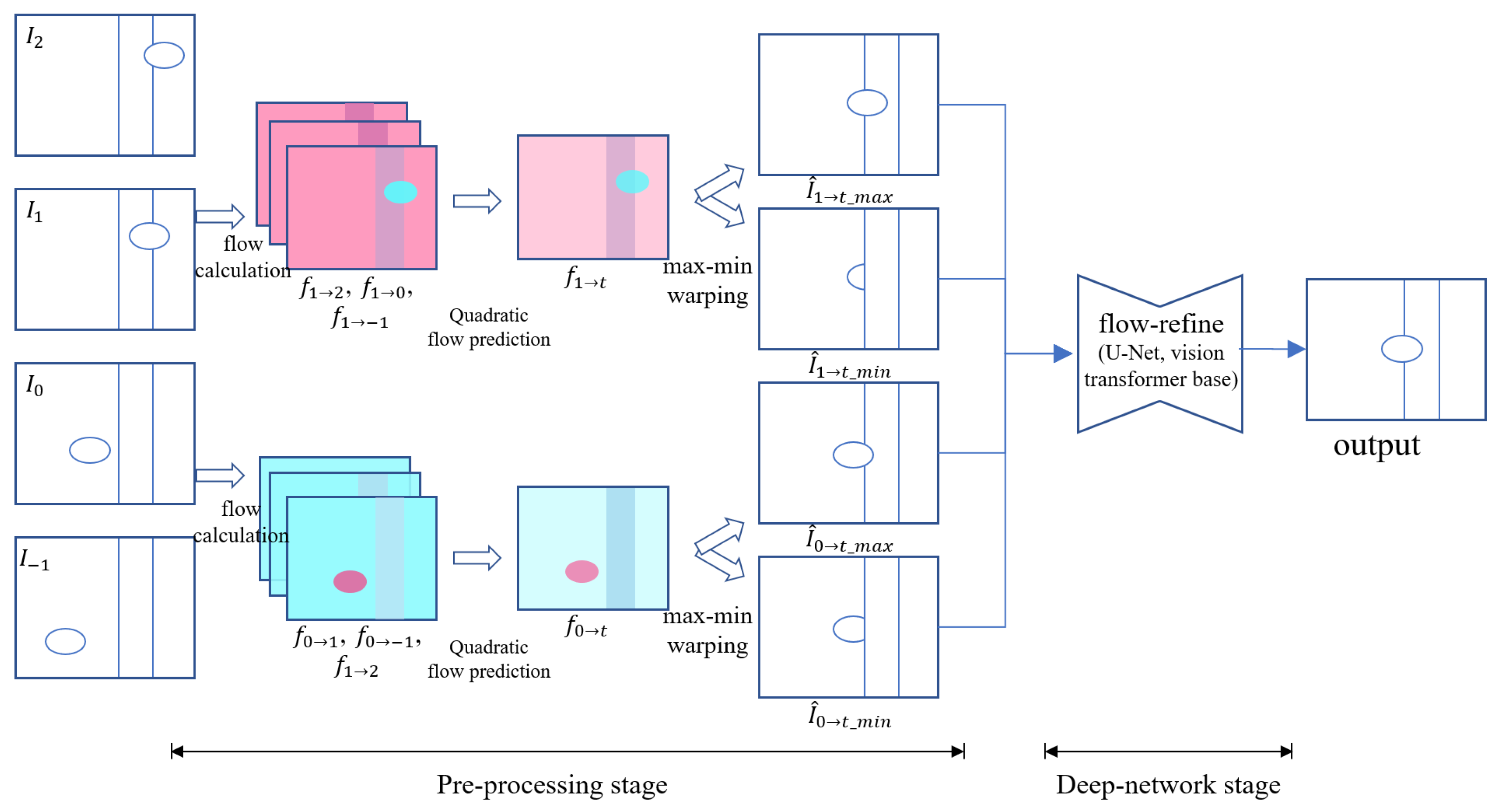
The approximate flow of the proposed network is as follows. As shown in
Figure 1, it can be divided into two parts: first, the pre-processing process, and second, the network. As in the overview of
Figure 2, given frames
, the input frame uses PWC-Net [
12] at the time of frame
to compute the flow map for the input, and the flow map for the input, at the time of frame
. Since the calculated flow map contains the
dx,
dy coordinates between two frames given 2ch,
for
of the target
t, interpolation can be generated by forward warping of the
frame.
3.1. Pre-Processing Stage
3.1.1. Accelerated Flow Map
When the flow map between the
frame and the
frame is
, the forward warping function
can be expressed as follows.
In EQVI [
13], for more accurate motion prediction, three flow maps obtained from pair images of PWC-Net assume the same velocity and constant and create a flow map toward the
t point. Given
, we can derive flow map
. Therefore, assuming that acceleration and velocity are
by substituting
and 2 in
t, the following matrix form can be obtained.
We can make better predictions for by solving the least-squares solution overdetermined for that matrix. However, in most frame interpolation methods, many errors occur in the process of reversing to . EQVI implemented the flow map as a forward warping method. According to this study, additional processing for holes and occlusions is required using forward warping, but in the flow map hole, pixels and represent , so the background image is still. Accurate results are guaranteed, but in the real world, the shooting angle is frequently changed with hand-held cams, or the background and the object move at the same time, so many errors occur in complex situations. Therefore, in the subsequent process, we propose a method to send an RGB image that is easy to understand by the deep network to the input of the deep network by directly warping and without performing the process of flipping to .
3.1.2. Max-Min Warping
When warping an image through a flow map, objects occlude the foreground or are occluded in the foreground. Therefore, in this paper, a pre-warped image through max-min warping is used as an input to the network, and training is carried out so that the network can select an appropriate image from these two situations. Due to this, it can be expected that the network forms a morphologically new object. The proposed max-warping and min-warping methods mean taking the value of the pixel with the largest max value of the motion vector among the occlusion regions after forward warping. This process was implemented with the pytorch scatter max package. The formula of the existing forward warping method can be expressed as follows. The forward warp function of the image
for the flow map
can be expressed as
and the output
can be expressed as follows.
where
, which means the Gaussian weight by the distance between the pixel locations
u and
x. Since
u represents the numerically adjacent
in the range of
to
x. As a result,
u at the time of forward warping
t is a weighted average of
x pixels projected to the pixel’s neighborhood. Therefore, when warping is performed with this forward warp function, there is a problem that the intensities of the moving object and the background pixel are blended to an average, so additional processing is required for a clearer result. For this occlusion, we propose two methods of warping that take the value of a specific pixel
u as the max or min according to the size of the motion vector after the warp. The max-warping function
and the min-warping function
can be expressed as follows,
The sample value of the pixel with the largest or smallest motion vector size among the pixels adjacent to
for the pixel
u is at the
point of argmax and argmin. Finally, by using input
the accelerated result
can be found. The warping result of this is
and
; alternatively, using the input
gets the accelerated result
with
and
. As shown in
Figure 2, the total of four max-min warping results can be completed. Further, since the flow map contains segment information about the movement,
and
of the 2ch flow map is also sent as a network input together.
We described how to perform EQVI and max-min warping after obtaining a flow map with PWC-Net for inputs
and
. Here, since the flow map output result of PWC-Net is learned from CG images with an object’s ground truth, it shows the movement of an accurate object in general, even for complex object movement, but it learns to minimize the endpoint error (EPE), which is a loss between the movement endpoints between pixels. Because of this, it may become blurry at the boundary of objects that are not probabilistically clear. This is because if DT-blur [
14] is used, the edges of the flow map can be sharpened by using the RGB image as a guided image at a low computational cost, so DT-blur is additionally used for the flow map output of PWC-Net. With only the flow map sharpening effect, warping performance is improved and PSNR is improved.
3.2. Deep Network Stage
3.2.1. Channel and Spatial Attention
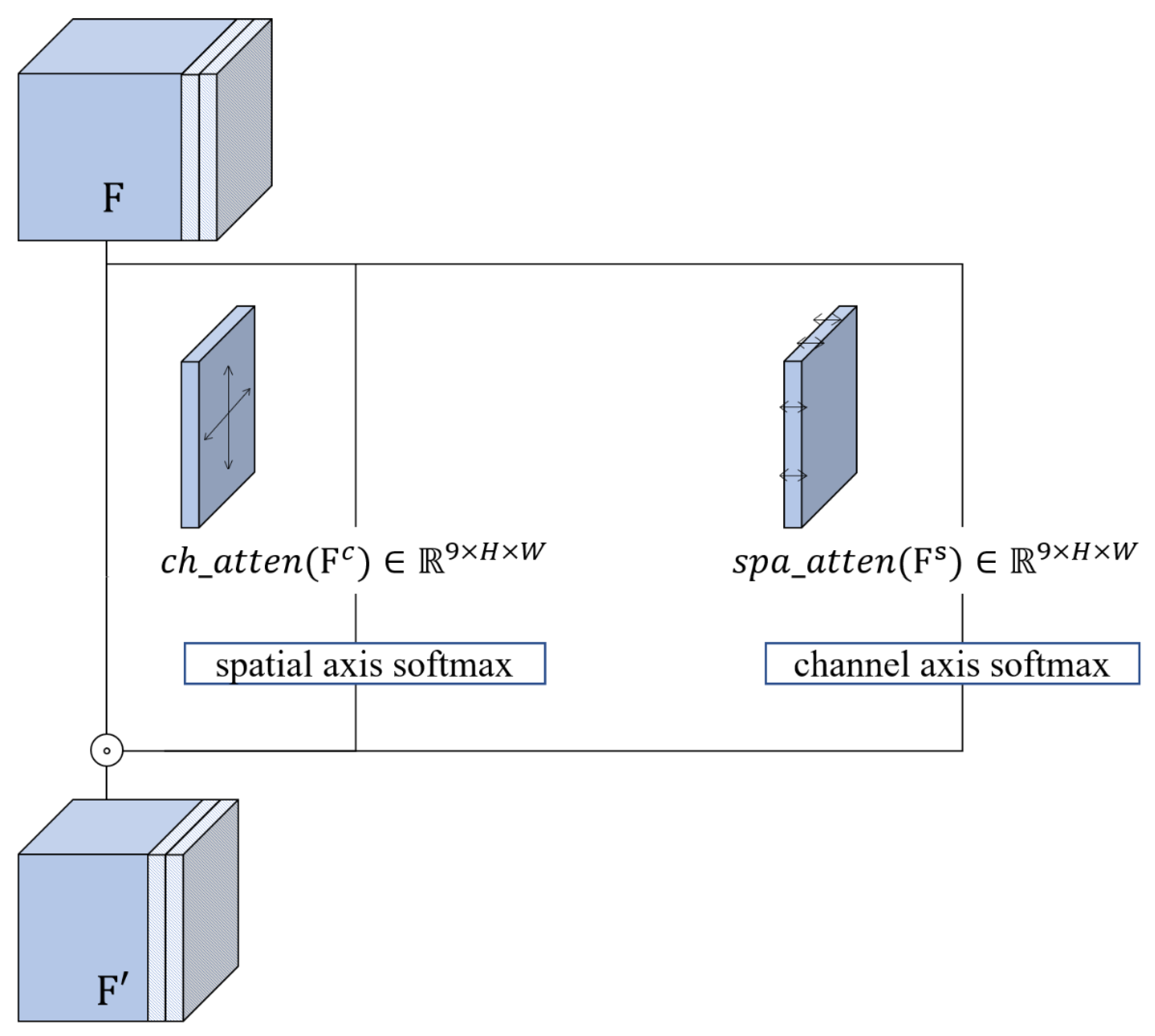
Our entire network has a U-Net structure. However, due to the nature of the task of VFI, the calculation of dividing the foreground and background according to the movement size of an object is frequent, so a block that helps self-attention calculation is added after the up and down process of U-Net by adding a learnable output channel. In the corresponding block, the softmax operation is performed by separating n channels after the up and down blocks, as shown in
Figure 3, and the original channel is multiplied again. Channel attention and spatial attention are used simultaneously, and the specific formula for the input feature map is as follows. Assuming that the given input feature map is
, the channel axis feature map is
, and the spatial axis feature map is
, the channel attention performs the softmax operation by collecting spatial axis elements, and spatial attention performs softmax by collecting channel axis elements. where
n was used 18 for the pre-added channel because three extra RGB-channel images were subjected to each channel attention and spatial attention.
Similarly, spatial attention can be writen as follows.
The completed nine-channel softmax channel performs an element-wise product operation on the original input size of channel for attention. As a result, the original channel size is maintained.
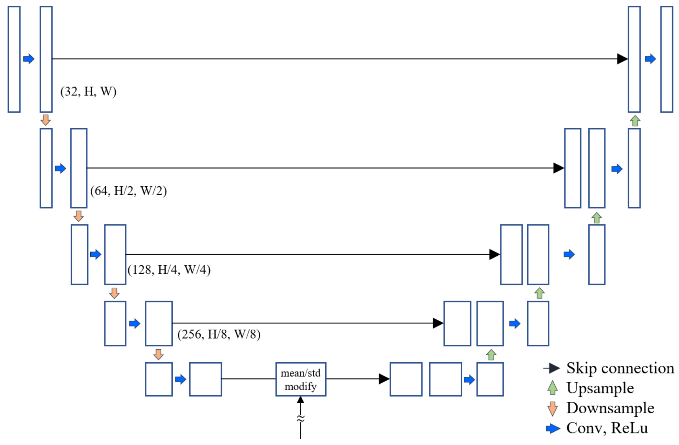
3.2.2. Stacked Context Switching Structure
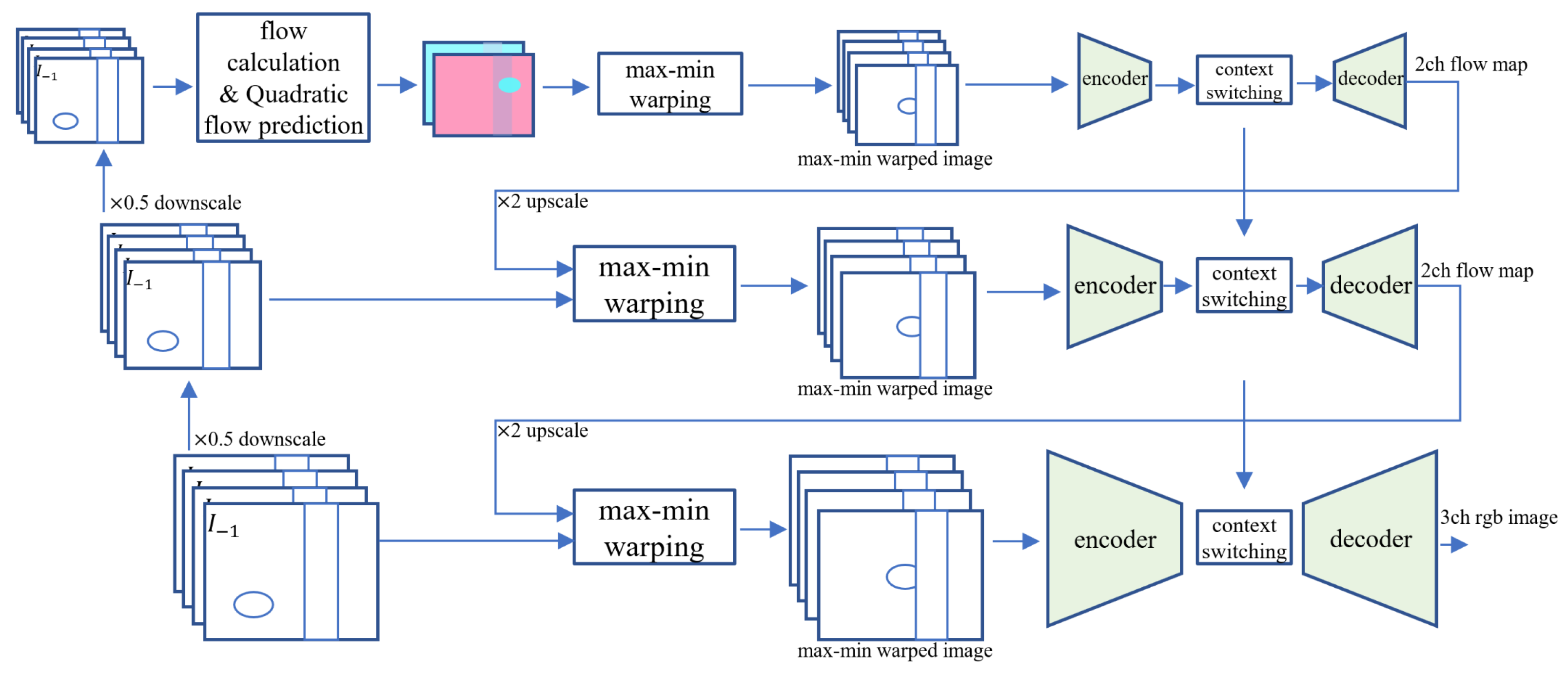
In this paper, we use the structure of a stacked U-Net consisting of three scales as shown in
Figure 4. Judging from the previous VFI studies, there were many cases of significant subjective performance improvement just by stacking U-Net networks in series several times. It is presumed that each U-Net network makes a deblurred and motion-aligned image alternately. The input image is bi-linearly downscaled to ×0.5 and ×0.25, respectively. From the image of the deepest scale, flow calculation using PWC-Net and quadratic flow prediction is performed. Then the max-min warping process is performed through the generated flow map toward the
t time point to generate four images for each warp and input to U-Net. After going through the encoder of U-Net, it goes through a context switching step that changes the mean and standard deviation of the feature map. This step was borrowed from the AdaIN block of the style transfer study [
15].
As in Equation (
9), if the latent vectors through the network are well encoded, it is a study that can change the style, such as the lighting direction or atmosphere of the image, only by changing the mean and standard deviation of the feature maps. It has the same effect on the upper depth of the mean and standard deviation learned from the deepest network and is configured to be learnable. After the decoding step, outputs repeat the max-min warping process again with the refined flow map after upscaling. The more detailed feature map size and number of channels of U-net are shown in
Figure 5. The ×1 scale uses four depth levels of U-Net, and the ×0.5 and ×0.25 use three depths and two depths of U-Net, respectively.
4. Experiments and Discussion
To evaluate the impact of the proposed method, we conducted objective and subjective performance evaluations together with the conventional video frame rate interpolation algorithm and experimented with examining whether the network receiving max-min warping works as we intended. First, the detailed implementation details not described above are as follows.
4.1. Implementation Details
Training dataset. The training set of Vimeo septuplet was used for training. Although the Vimeo dataset has a variety of advantages, the image is not clear, and the size of the movement is not uniform. If the size of the movement is not uniform, the learning is unstable at a high learning rate. In addition, if the optical characteristics of the camera are not good, it learns the motion blur tendency that occurs when the size of the movement of the subject increases, which can lead to bad results. Therefore, in this paper, the GoPro imaging dataset used in deep video deblurring was added [
16]. The sum of the Vimeo64k set and the random 64k set of GoPro images was composed of 1 epoch.
Argumentation. Our network training method uses self-supervised learning that uses four even-numbered frames as input and one central odd-numbered frame as output. The input image uses a patch size of 256 × 256 at a random location in the dataset and uses a random horizontal flip of the image. Further, to prevent the network from memorizing the temporal sequence of temporal frames, we use a method to reverse the temporal sequence of the frames.
Network details. In the downsampling process of U-Net, a typical U-Net using average pooling downsampling and bi-linear upsampling is used, and an attention layer is added for every convolution at the end of the layer. The input channel is four input images, 2 for object segmentation information and four images obtained by max-min warping with two flow maps. It consists of a total of 28 channels of input and 3 channels of RGB output. Since U-Net repeats multiple levels of downsampling and upsampling in parallel, it is difficult to learn high-level features. A low learning rate was used for stable learning.
Loss function. For the loss function, the reconstruction loss
was used, and as a perceptual loss, a part of the encoder of layer 4–3 of VGG16 [
17] was used. We used the perceptual feature loss with a coefficient of 0.005. In addition, the proposed method adds the edge loss. For the edge loss, we use the Sobel operator [
18] of the 5 × 5 kernel to add a loss to learn by focusing on the edges of the output image and the ground truth object; a coefficient of 0.002 is used.
Learning schedule. The optimizer uses the AdamW [
19] and CosineAnnealingWarmRestarts [
20] schedulers to reduce the learning rate by 0.8 times every 10 epochs, a total of 200 from 1 × 10
to 1 × 10
. Up to 150 epochs, the perceptual loss was excluded, and the remaining 50 epochs were trained by adding the perceptual loss as a fine-tuning step.
4.2. Experimental Results
We compared the proposed method with the conventional VFI algorithms, SuperSloMo, QVI, and the Vimeo90k, UCF101, and adobe240 datasets. As shown in
Table 1, the Vimeo90k dataset showed a PSNR improvement of 0.66 compared to QVI. Comparing QVI with the proposed network, considering that the max-min warp process and the flow synthesis part are different, it can be confirmed that the PSNR improvement effect is when using the proposed forward warping process rather than the backward warping process. Considering that most optical flow-based frame interpolation methods use the flow reverse process and backward warping, it is expected that the proposed warping method can minimize the loss due to flow reverse in other studies as well. Further, there is a slight decrease in SSIM, which seems to be due to structural loss in the image occlusion process in images with large movements. On the other hand, the performance improvement of the proposed algorithm was particularly large in UCF101. Since UCF101 has a low image quality and has blocking artifacts, it is expected that the effect of UCF101 will be improved while aligning the results of max-min warping of the proposed network in RGB space. In adobe240, both QVI and the proposed algorithm showed the highest PSNR, resulting in the smallest gap. Since this uses a 240 fps high-scan video, the size of the image motion tends to be small and uniform. Therefore, it seems that there is a high PSNR performance improvement in a method using a quadratic motion prediction method such as QVI.
To evaluate our proposed network computational complexity, we show the number of the learnable parameters and interpolation speed in
Table 2. The main network of SuperSloMo and QVI uses a U-Net base architecture, so the number of learnable parameters is similar. In the case of QVI, the number of parameters was slightly increased because mask-net was added to the final synthesis process. On the other hand, the proposed networks significantly reduced the number of parameters by removing the fifth depth in U-Net. Nevertheless, it shows high PSNR performance because our networks go through U-Net several times, as much as the reduced amount of computation in the downscale process. The runtime column represents the time of the interpolated image in the Vimeo90k dataset with a batch size of 15. In the case of SuperSloMo and QVI, the runtime seems to be larger than the proposed method because of the additional computation in the visible mask process.
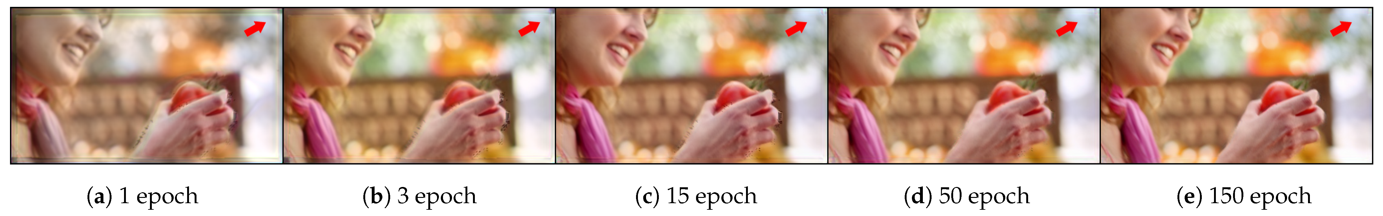
In
Figure 6, we examined every few epochs to evaluate whether the proposed network input max-min warp is effectively learned. For the hole interpolation experiment, we arbitrarily selected 1, 3, 15, 50, and 150 epochs. In the upper right, we can find the holes and misalignment in the images of
and
after the warp. As the learning progressed, an interpolated image was created by using the two images appropriately, and in the case of the hole region, it can be seen that the network creates a plausible patch as we intended. Due to this principle, compared to other flow-based methods such as QVI, the proposed method is clear, and the frame edge area appears natural.
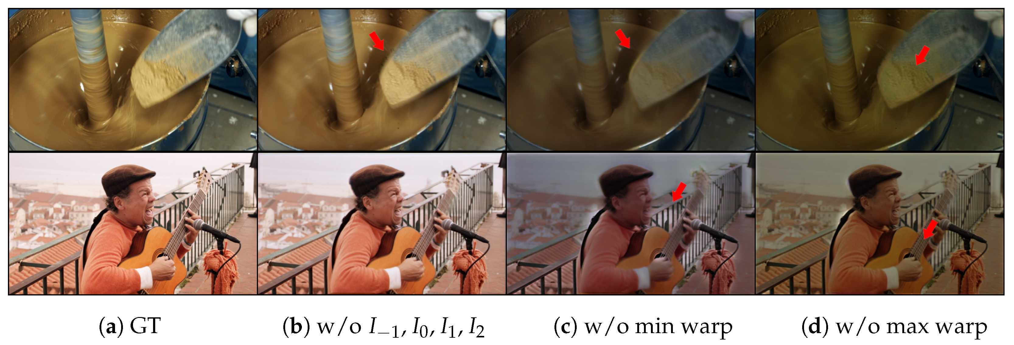
In
Figure 7, it was evaluated whether the proposed network uses the max-min warped image for its intended purpose. We decided to guess how the network utilizes those frames by replacing some of the input frames with black frames. First, as a result of inputting black frames instead of
frames, as shown in
Figure 7b, black holes were found in the area of a large movement. This shows that the network completes the output by referring to the
frames for the hole region that occurs after the max-min warp. Further, as in
Figure 7c, as a result of inputting a black frame to the min warped image, it can be seen that the edge of the moving object is brighter. It can be seen that the network is concentrating on the moving edges of the max warp image. Similarly, if the max warped image is removed through
Figure 7d, it can be seen that the min warped image is focused on the texture detail inside the object rather than the structure of the movement. It was visually confirmed that the network is using the max-min warping image proposed through the experiment.
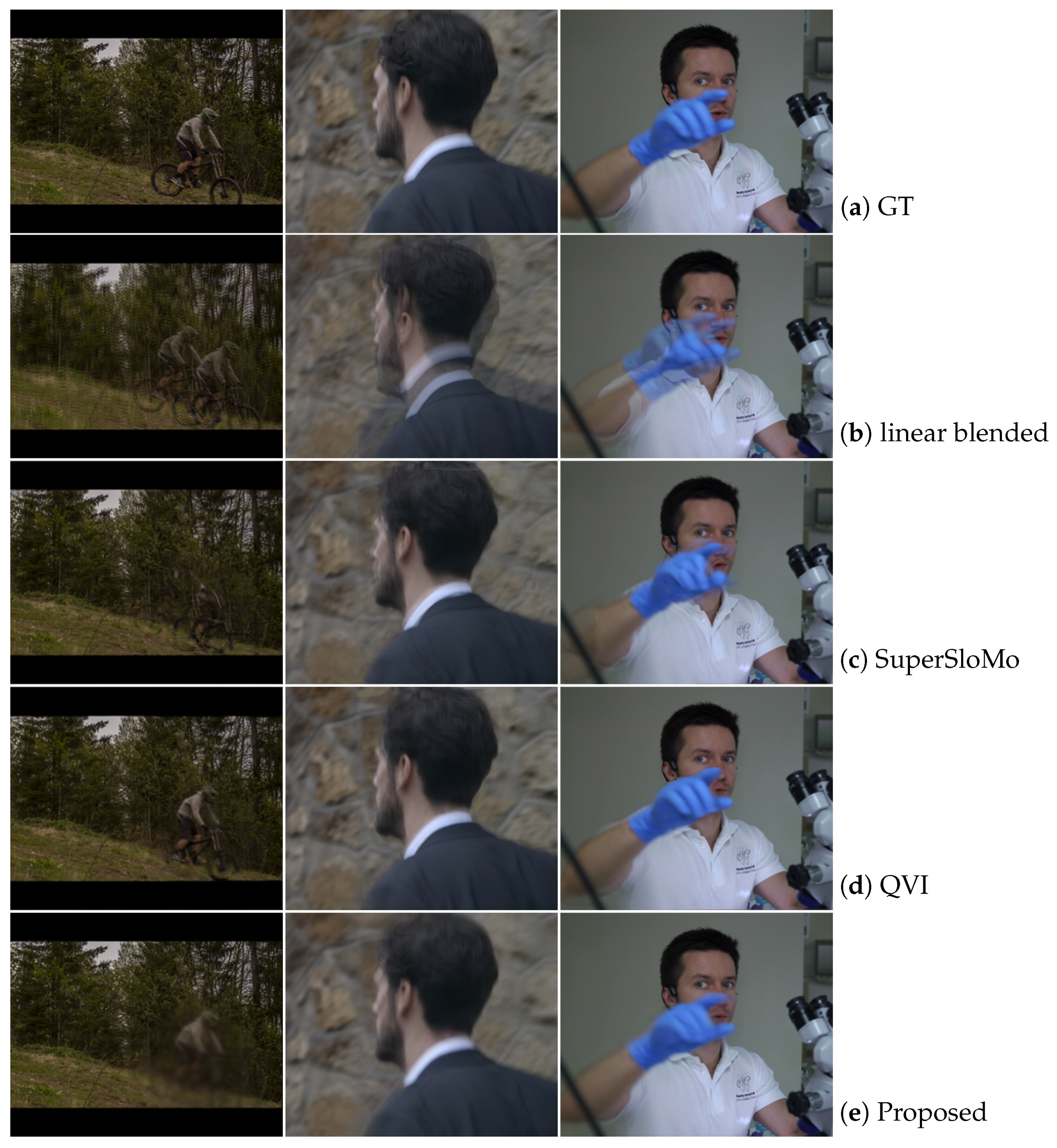
Figure 8 is a subjective image comparison between the proposed method and major frame interpolation methods. The image of the bike on the left is a fast-moving bike against a background of trees with high texture detail. In such a scene, it is difficult to properly separate the motion with the optical flow. SuperSloMo failed to recognize a moving object and QVI recognized the object, but the detailed outline of the bicycle could not be classified, leading to a drop in PSNR. In the proposed method, motion blur is learned in the warp region with a lot of movement, so it has a blurred appearance, but an overall high PSNR is obtained. In the central image, the proposed method showed the most natural interpolation performance in the frame edge region. In the image on the right, the hand is out of focus. In QVI, the outline of the hand is compressed, and the interpolation is excessively clear, but it can be seen that the proposed method shows adequate interpolation performance.
4.3. Ablation Study
To compare the contributions of the proposed components, in
Table 3, PSNR was compared by excluding the proposed components from the Vimeo90k dataset one by one. If the PSNR drop is large after removing each component, it can be interpreted that the contribution of the component is large. The w/o max-min warping is implemented similarly to the method of using flow reversal
as a network input used in the backward-warping process in QVI. As the largest PSNR drop is present in w/o max-min warping among the main components, it can be seen that the contribution occupied by the proposed network is the highest. By removing the DT-blur, it can be seen that there is a slight PSNR improvement just by giving a sharp edge in the flow map. In addition, the gathering process through the attention block also shows superior results compared to the computation cost. We experimented with w/o stacked U-Net by replacing three scale networks with conventional U-Net. The proposed stacked U-Net structure showed superior subjective performance improvements but did not achieve significant improvements in objective figures. With the use of perfunctual loss, subjective image quality was significantly improved, but in terms of PSNR, a decrease was rather confirmed.
4.4. Discussion
Optical flow-based frame interpolation methods have high subjective image quality as a reliable classification of moving objects. However, since the interpolation image is limited only to the interpretation of the movement of the flow, the interpolation performance decreases when a morphologically different image appears. Therefore, in recent years, the network tends to change to a method that directly generates an RGB image, but due to the nature of the frame interpolation method, a linear blended image such as
Figure 8 also has a fairly high PSNR. Therefore, it is difficult for the network to understand and learn the image in the movement space. Since the proposed network reduces the spatio-temporal search range through max-min warping, RGB image output can be applied, and PSNR is also high. In this paper, we experimented with only one output, but as the complexity of the network is reduced, it is expected that continuous time interpolation such as a flow-based network will be possible by newly learning a network that outputs 4x or 8x frames in the future.


