1. Introduction
With the development of microelectromechanical systems (MEMS) technology, the performances of MEMS devices are greatly improved, and now the sensors are widely used in various fields [
1]. As one crucial kind of MEMS sensors, MEMS inertial sensors have been widely adopted into many areas, such as aerospace, vehicle navigation, and consumer electronic products, including smartphones, tablets, and wearable sensors [
2,
3].
Microinertial devices, as one kind of MEMS device, mainly consist of microaccelerometers and microgyroscopes. The accelerometer acts as an inertial sensor that detects the linear acceleration or velocity of an object’s motion, whereas the gyroscope detects the angular velocity (rate) or angle (rate integrating) of an object’s rotation [
4].
For inertial sensors, high integration is a significant development trend. Both microinertial measurement unit (MIMU) and microinertial navigation system (MINS) are designed to improve the integration of devices to achieve more measurement functions in a smaller volume and meet the requirements of small volume, low power consumption, and multifunctionality of equipment. At present, high-precision MEMS IMU mainly adopts three single-axis accelerometers and three single-axis gyroscopes through three-dimensional assembly. For example, Honeywell has developed a microinertial measurement combined product, HG1930. However, there are problems such as large size, high cost, and installation errors for this method [
5]. Therefore, under the premise of ensuring high precision, reducing the number of inertial devices and even achieving the chip-level integration have vital research significance and application value.
The microresonant accelerometer, which converts the acceleration signals to be tested into the frequency variation of the resonator, has attracted considerable attention in the research and development of high-precision MEMS accelerometers. It has the advantages of quasidigital signal output, high sensitivity, high resolution, wide dynamic range, anti-interference capacity, and good stability [
6,
7,
8]. It is now one of several new-generation, high-precision MEMS accelerometers.
The micro-Coriolis vibration gyroscope (CVG), based on the Coriolis principle, is an excellent candidate to be a MEMS gyroscope. The MEMS ring resonator with two-dimensional symmetrical structure characteristic is well suited for the traditional MEMS manufacturing process and can achieve low-cost mass production [
9]. Compared to MEMS tuning fork gyroscopes, ring gyroscopes with the symmetrical structure have the following prominent advantages [
10,
11,
12]: (1) high sensitivity and less drift resulting from the same mode frequency and quality factor; (2) better resistance to external shocks and undesired vibrations. Therefore, the ring gyroscope is considered as a candidate for high-performance MEMS gyroscopes.
Silicon has the advantages of easy purification, stable chemical properties, and low cost, making silicon the most widely used semiconductor material [
13]. Because the MEMS processing technology and integration technology based on silicon (SI) material are very mature, the silicon-based inertial sensor has become the most widely used device. Through the analysis of the MEMS silicon ring gyroscope and MEMS silicon resonant accelerometer, it is found that they are both two-dimensional structures and manufactured based on bulk silicon technology, which makes them very suitable for integrated design. In addition, the current situation of the ring gyroscope and resonant accelerometer has fully verified that they can achieve medium and high performance.
This paper proposes a single-chip integrated accelerometer gyroscope, which consists of a microring gyroscope and a MEMS resonant accelerometer. The accelerometer is located inside the gyroscope and the two structures are concentric. This novel structure integrates a ring gyroscope and a resonant accelerometer into one single-chip structure, which can measure both the acceleration and the angular velocity (or the angle). At the same time, it has the advantages of small volume, low cost, and high precision. When applied to MEMS IMU, the number of devices can be reduced from the traditional 6 to 3, which will have significant advantages in terms of volume and so on. The rest of this paper is organized as follows.
Section 2 gives the operating mechanism and detection mode of ring gyroscopes, with emphasis on the rate mode and rate integration (RI) mode in
working mode. The operating mechanism of the resonant accelerometer is introduced in
Section 3. Combined with the content submitted in
Section 2, it can guide the structure design.
Section 4 presents the whole structure of the proposed single-chip integrated accelerometer gyroscope and introduces the components of the structure in detail. Then, modal simulation and performance analysis are given in
Section 5, which includes modal analysis, input–output characteristics analysis, and thermal analysis by using ANSYS software. Moreover, the applicability and the availability of the proposed structure are verified through the FE simulation. Finally,
Section 6 concludes this paper with a summary.
2. Operating Mechanism and Detection Mode of Ring Gyroscopes
In 1890, G.H. Bryan proposed that when a vibrating axisymmetric shell rotates around its central axis, the circular vibration mode precesses proportionally to the shell and is no longer stationary relative to the shell [
14]. This phenomenon is called the Bryan effect and is used for angular velocity or angle detection by ring gyroscope.
The ring gyroscope usually operates in
n = 2 mode (four antinodes), which takes the form of a standing wave shape, as shown in
Figure 1. To facilitate understanding,
Figure 1 decomposes the vibration of the ring resonator according to the electrode axes, and the electrode angle corresponding to the
n = 2 is 45°, which is the angle between the two standing waves. When there is no angular velocity or angle input, the ring resonator maintains a fixed antinode position (standing wave). When the sensitive axis of gyroscope rotates, the standing wave will precession and become a traveling wave. The input angular velocity or angle can be calculated by standing wave precession.
The operating mechanism based on the Bryan effect (standing wave precession) allows the ring gyroscope to have the dual function of detecting angular velocity and angle [
15]. Correspondingly, the MEMS ring gyroscope has two detection modes, rate mode [
16,
17,
18] and rate integration (RI) mode [
19,
20,
21], as are shown in
Figure 2.
Figure 2a shows the rate mode, the most common detection mode of MEMS CVGs, which detects the input rotation velocity. In this work mode, the ring gyroscope measures the rotation rate, which is proportional to the Coriolis force. Usually, the two vibratory modes are defined as drive mode and sense mode, wherein, the ring gyroscope is excited in the drive mode and is fixed to a particular axis (along the axis of the drive mode electrode) with a constant amplitude, which is maintained by the automatic gain controller (AGC). When there is angular rate input, the vibration of sense mode will be triggered under the Coriolis effect (the energy is converted from drive mode to sense mode). Therefore, the wave nodes of drive mode will vibrate, as are shown in
Figure 2a. The rate mode can be divided into open-loop detection and closed-loop detection. The open-loop detection measures the input by sensing the vibration produced by Coriolis force, whereas the closed-loop detection measures the input by suppressing the vibration by force balance controller.
For the open-loop detection mode, when there is an angular velocity
input, the vibration amplitude of the sense mode
can be expressed as [
22],
where,
k is the precession factor, which is constant for the actual structure,
Q is the quality factor of the ring gyroscope,
is the working frequency, and
is the vibration amplitude of the drive mode.
For the closed-loop detection mode, the balancing force
to counteract the Coriolis force effect is given as
where,
is the driving force of drive mode.
Figure 2b shows the rate integration mode, also known as whole angle (WA) mode, which directly detects the input rotation angle. The working principle is the Bryan effect that the rotation angle of the standing wave will always lag behind the rotation angle of the carrier by a fixed angle(
), as shown in
Figure 2b. Unlike the rate mode, the vibration in this mode will not be locked in a fixed axis upward but will achieve free precession with rotation. The input angle
can be obtained by determining the precession angle
of the standing wave.
3. Operating Mechanism of Resonant Accelerometers
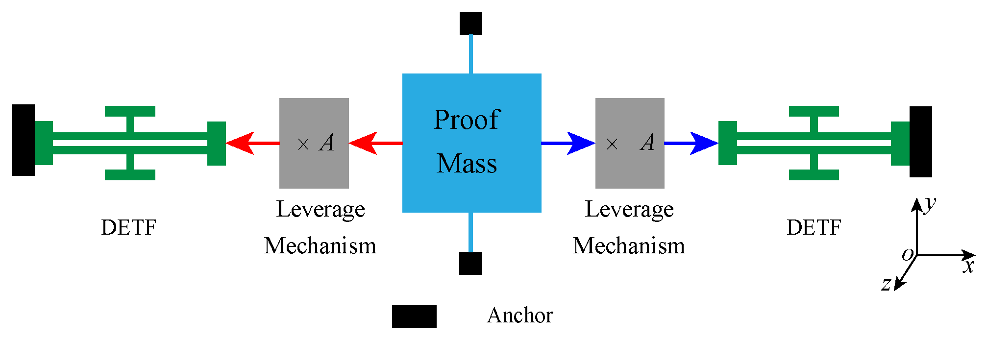
Differential output resonant accelerometer has become the most popular structural form of the resonant accelerometer because it can significantly reduce the influence of common mode errors such as temperature and stress on the output.
Figure 3 shows the structural diagram of the MEMS silicon resonant accelerometer, a perfectly symmetrical differential structure.
Two double-ended tuning forks (DETFs), which serve as stress-sensitive resonators, are symmetrically arranged and connected to the proof mass by leverage mechanism. The proof mass converts the input acceleration into an inertial force, which is amplified by leverage and then transmitted to the resonators. The inertia force will cause the changes of resonant frequencies, which shows that the frequency decreases under compressive force and increases under tensile force. The magnitude of the input acceleration will be calculated from the difference between the resonant frequencies of the two resonators. According to [
23], the resonant frequency of DETFs under inertial force are as follows:
where,
f is the resonant frequency of DETFs under inertial force,
is the unloaded resonant frequency, ± denotes the tensile force and the compressive force on the DETFs,
L is the length of the resonant beam,
h is the thickness of the resonant beam,
is the width of the resonant beam, and
E is the elastic modulus of the structural material.
With the high-order terms omitted, the differential frequency output of the accelerometer is given as follows [
23]:
4. Design of the Whole Structure of Single-Chip Integrated Accelerometer Gyroscope
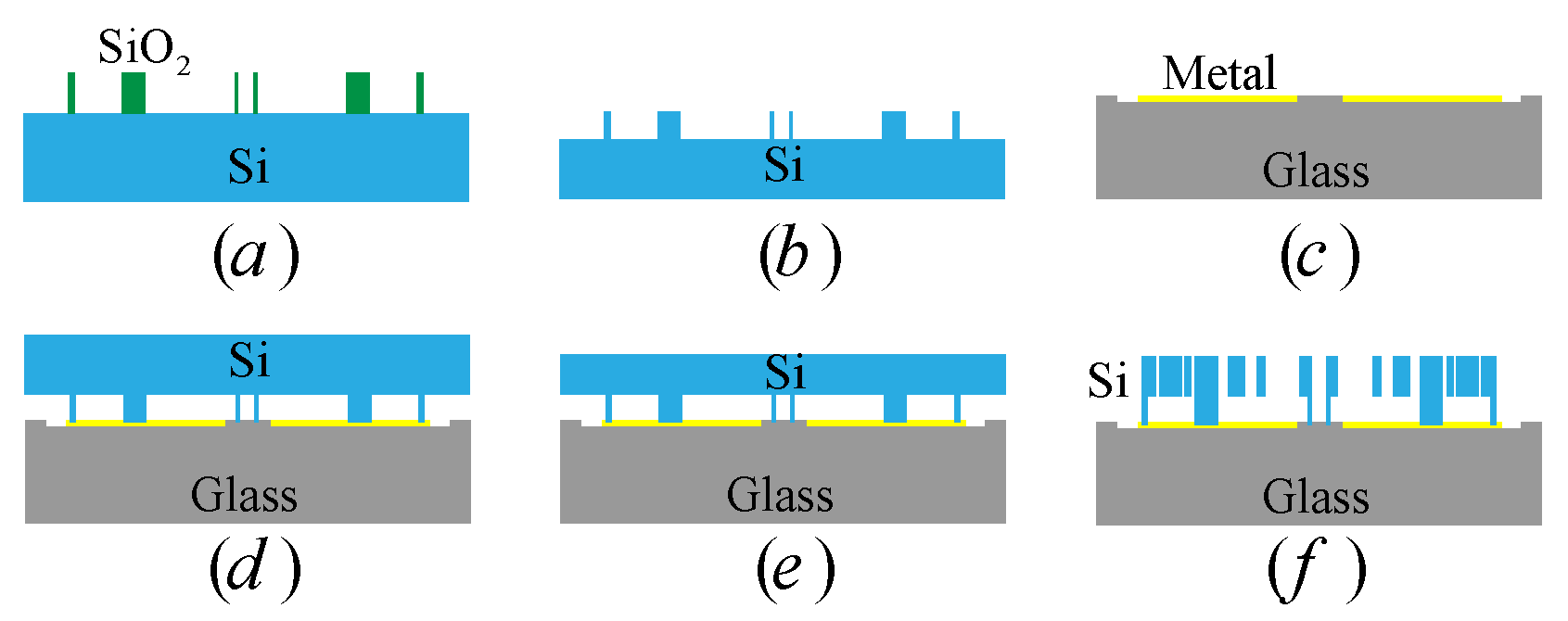
Based on the deep dry silicon on glass (DDSOG) processing technology, a single-chip integrated accelerometer gyroscope is proposed. The procedures of the DDSOG technology are shown in
Figure 4 [
24]. The DDSOG process is simple and the yield is high. This process has a larger aspect ratio than the surface processing process. In particular, the movable structural material of the device is single-crystal silicon, and the internal stress is very small. The high temperature process and the recombination of other materials on the structural layer are avoided during the processing. Therefore, the stress and stress gradient of the final device structure are small [
25].
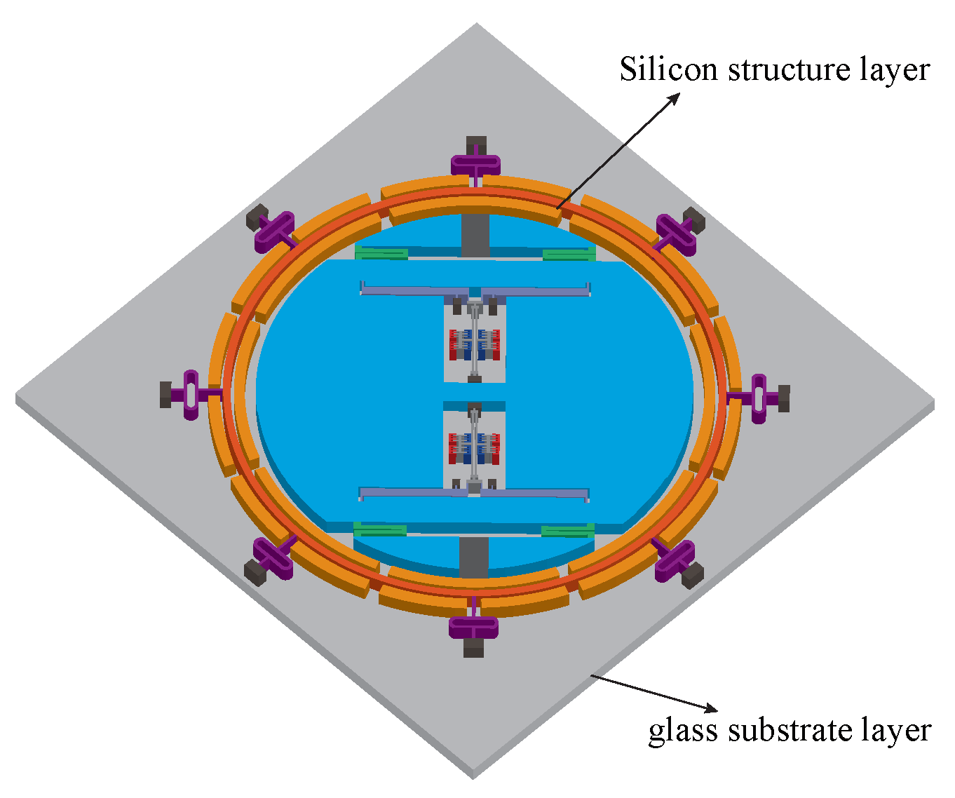
The proposed single-chip integrated accelerometer gyroscope is shown in
Figure 5, consisting of a microring gyroscope and a MEMS resonant accelerometer. The accelerometer is located inside the gyroscope and the two structures are concentric. In the figure, the different colors of the silicon structure layer are only to distinguish different components of the structure, and the subsequent analysis is only performed for the silicon structure layer.
For
, the working mode of a ring gyroscope (the drive mode and the sense mode are two identical elliptically shaped flexural modes with equal natural frequencies and are 45 apart from each other), at least eight support beams with central symmetry are required. In addition, to realize the detection of gyroscope, at least eight groups of centrally symmetrical electrodes are needed. Therefore, the structure of the ring gyroscope (
) is designed as shown in
Figure 6a, which consists of a ring, eight support springs, fixed electrodes, and anchors. The support spring is a
-shape structure, and a group of electrodes is composed of an outer electrode and two inner electrodes.
The structure of the inner accelerometer is designed according to
Figure 3. In order to make better use of the structural space, the inner accelerometer is designed as a circular structure.
Based on the previous research on the resonant accelerometer and the ring gyroscope [
23,
26,
27], combined with the current DDSOG technology level, the main structural parameters of the accelerometer gyroscope are set as shown in
Table 1.
5. Modal Simulation and Performance Analysis
5.1. Modal Analysis
As is known to all, too low a frequency of the translational mode of proof mass (usually the first mode) will be affected by the vibration, shock, and audio noise. Too high a frequency of the working mode will bring difficulties to circuit detection and control. Therefore, the translational mode frequency of proof mass is designed above 2 kHz, and the working mode frequencies of DETFs and ring gyroscope at most 30 kHz are designed.
The material properties of silicon are listed in
Table 2 [
28,
29]. The mode analyses of the single-chip integrated accelerometer gyroscope are carried out and shown in
Figure 7, and the mesh element is SOLID 95.
The resonant frequencies of upper and lower DETFs are 28,944.8 Hz and 28,948.0 Hz, respectively. The resonant frequencies of the ring gyroscope () are 15,768.5 Hz and 15,770.3 Hz, respectively.
In addition, the effective mode and interference mode are obviously separated. The modal simulation results show that the basic principle of the single-chip integrated accelerometer gyroscope is feasible.
5.2. The Input–Output Characteristics Analysis
Some articles directly give the ring gyroscope that the precession factor is a constant of 0.37 [
22]. Therefore, this paper focuses on the input–output characteristics of the resonant accelerometer. As described in
Section 3, the frequency variation of the two resonators of the accelerometer reflects the magnitude of the input acceleration. Generally, for resonant accelerometers, the frequency change is directly or approximately proportional to the input acceleration. The ratio is defined as the scale factor and can be given as
for the differential resonant accelerometer, which is determined by the structural form and structural parameters.
By applying a series of accelerations on the y-direction to the accelerometer, the corresponding frequency under the acceleration input can be obtained.
Table 3 shows the resonant frequencies of the two DETFs at an acceleration input varying from −20 g to +20 g.
Figure 8 shows the curve of the frequency difference between the two DETFs with the input acceleration. Through linear fitting, the scale factor of the resonant accelerometer is calculated as 83.5 Hz/g.
5.3. Ananlysis of the Affection of Acceleration on the Vibratory Ring Gyroscope
The accelerometer structure is designed to have only one degree of freedom in the Y direction, so it has excellent resistance to angular velocity interference. Therefore, this paper mainly analyzes the affection of acceleration on the vibratory ring gyroscope.
Because the gyroscope is a rotationally symmetrical structure, the analysis of one-eighth of the angle range is enough.
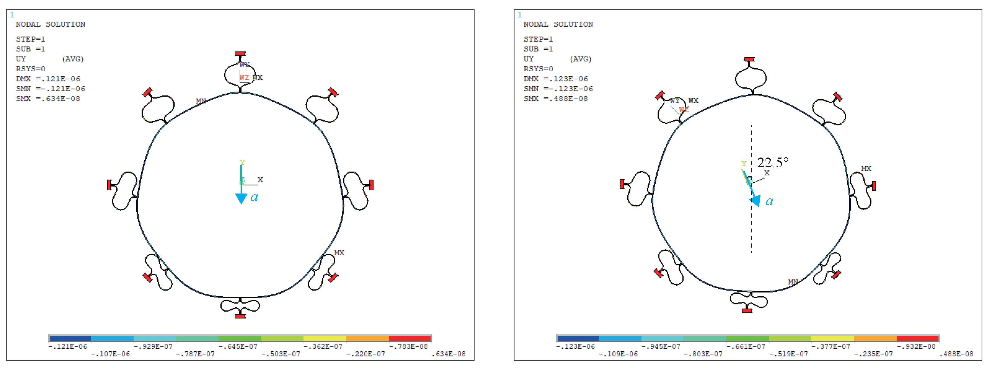
Figure 9 gives the acceleration application direction, all other application directions can be superimposed by these two directions. A series of accelerations are applied along these two directions.
The inertial force generated by the acceleration may cause the displacement change of the gyroscope. In addition, the inertial force is used as a prestress for modal analysis to see its impact on the modal frequency. The influence of acceleration on the gyroscope is analyzed by analyzing the displacement change and frequency change of gyroscope caused by acceleration load.
The simulation starts with the applied acceleration of 1 g. The simulation results show that 1 g acceleration has no effect on the displacement and working frequency (
) of the ring gyroscope. The acceleration load has been increased for simulation analysis.
Figure 10 shows the displacement distribution of the ring gyroscope when the acceleration is 100 g.
It can be seen that under the 100 g acceleration loads in the two directions, the maximum displacements of the gyroscope are 6.34 nm and 4.88 nm, respectively. At the same time, the working frequencies of the gyroscope are still 15,768.5 Hz and 15,770.3 Hz. Therefore, it can be concluded that the ring gyroscope in the designed structure has excellent resistance to acceleration interference.
5.4. Thermal Analysis
Due to the difference in the thermal expansion coefficient between the silicon structure layer and the glass substrate layer, the mismatch thermal stress will be produced as the temperature changes. In addition, the fluctuation or change of temperature will lead to structural deformation and the variation of the elastic modulus and the structural stress. These will cause the resonant frequency drift caused by the change of the temperature [
30], and has an important influence on the performance of the accelerometer gyroscope [
31].
A thermal analysis simulation is performed for the accelerometer gyroscope. The thermal stress caused by the temperature change is imposed on the structure as the prestress, and structural dynamic analysis is performed. The modal frequency variations with temperature changes from −40 to 60 °C are shown in
Figure 11. The simulation results demonstrate that the working frequencies of the DETFs are susceptible to temperature and the resonant frequencies drift reaches 20.1 Hz/°C. In contrast, the working frequencies of the ring gyroscope (
) are almost insensitive to temperature.
According to the analysis in
Section 5.2, the frequency difference between the two resonators of the accelerometer reflects the input acceleration. Therefore, to ensure the stability of the accelerometer, it is necessary to greatly reduce or even eliminate the influence of temperature on the frequency difference. It can be seen from
Figure 11 that although the working frequencies of two resonators are sensitive to temperature, they are highly consistent. With the advantage of differential structure, the influence of temperature on the two resonators can be well offset.
Figure 12 gives the frequency difference between the two DETFs at −40 to 60 °C, which shows that the frequencies difference is insensitive to the temperature. Therefore, the single-chip integrated accelerometer gyroscope has good temperature stability.
In addition, there will be enormous residual stress in the structure after the accelerometer is cooled from a high temperature to room temperature during processing or packaging, which will result in a large frequency deviation and may lead to structural deformation or damage.
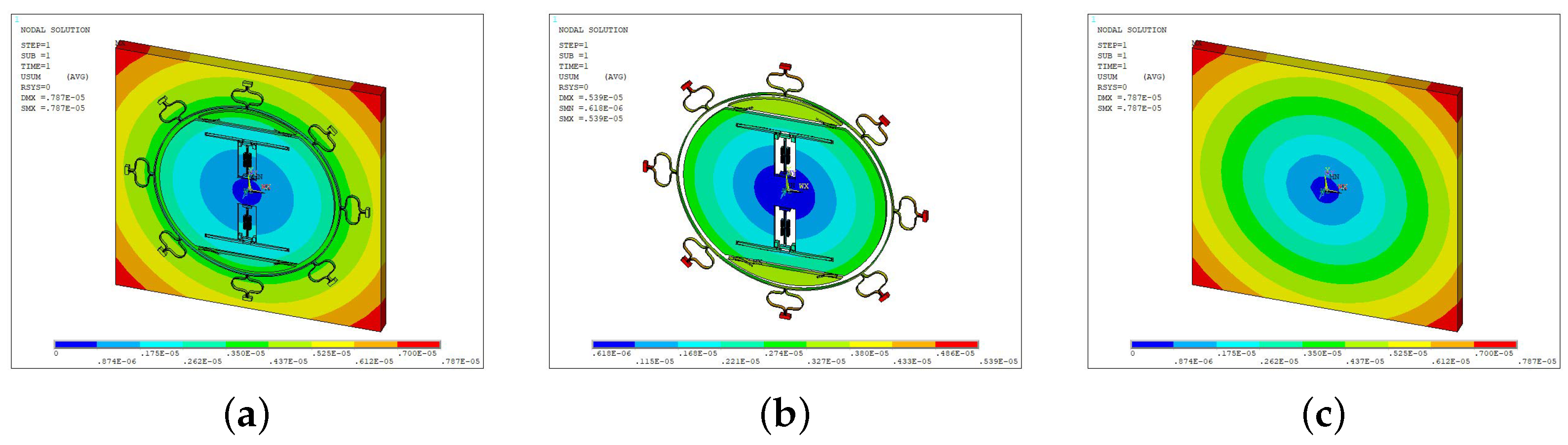
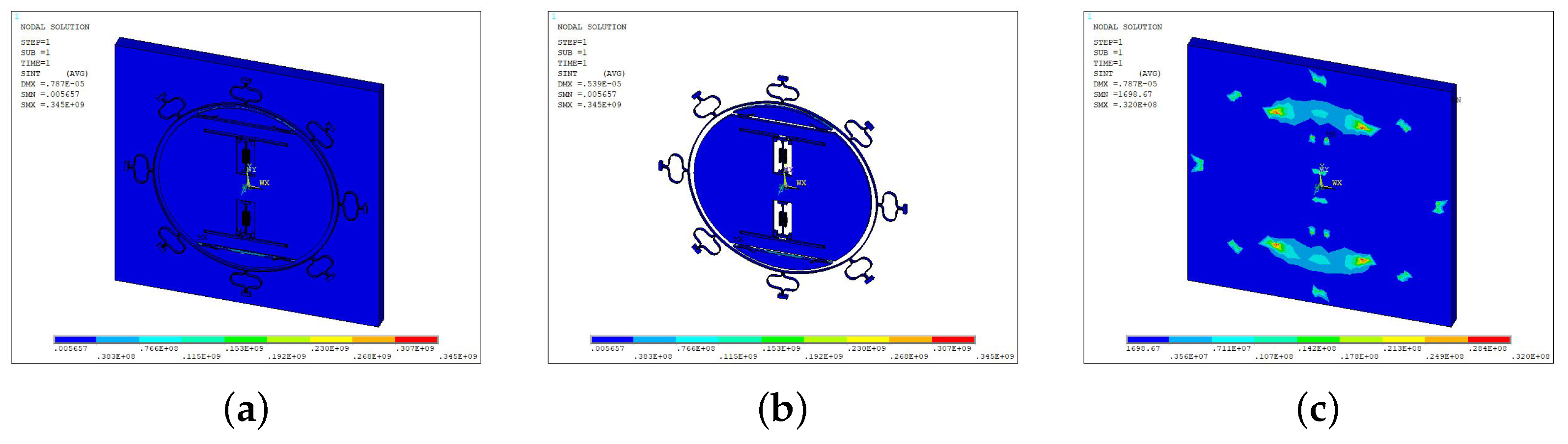
A thermal analysis simulation is imposed on the single-chip integrated accelerometer gyroscope at 400 °C (a high temperature of 400 °C is involved in an anode bonding process). The deformation and the stress distribution of the device are shown in
Figure 13 and
Figure 14, respectively.
The maximum deformation of the structure located in the substrate has a displacement of 7.87
m, whereas the maximum stress of the structure shown in
Figure 14 presents in silicon structures with the value of 345 Mpa, which does not reach the yield strength of 7 Gpa.
In summary, the thermal analysis fully demonstrates that the single-chip integrated accelerometer gyroscope has excellent immunity to temperature change.
6. Conclusions
In this paper, we have presented the design and simulation of a single-chip integrated MEMS accelerometer gyroscope, wherein a ring gyroscope and a resonant accelerometer are integrated into one single-chip structure. The accelerometer gyroscope can combine the advantages of the ring gyroscope and the resonant accelerometer, such as small volume, low cost, and high precision.
First, the operating mechanisms of the ring gyroscope and the resonant accelerometer are introduced. Then, the whole structure and main structure parameters of the proposed single-chip integrated accelerometer gyroscope are presented. Modal analysis showed the resonant frequencies of upper and lower DETFs in resonant accelerometer are 28,944.8 Hz and 28,948.0 Hz, and the resonant frequencies of the ring gyroscope () are 15,768.5 Hz and 15,770.3 Hz, respectively. The input–output characteristics analysis conducted the scale factor of the resonant accelerometer is 83.5 Hz/g. The accelerometer structure has excellent resistance to angular velocity interference, which benefits by the structural design of only one degree of freedom. In addition, anlysis results of the affection of acceleration on the ring gyroscope show that under the 100 g acceleration loads in the two directions, the maximum displacements of the gyroscope are 6.34 nm and 4.88 nm, respectively. At the same time, the working frequencies () of the gyroscope have not changed. The results demonstrate that the ring gyroscope in the designed structure had excellent resistance to acceleration interference. Finally, the thermal analyses are conducted. The simulation results show that the resonant frequencies drift of DETFs reaches 20.1 Hz/°C, whereas the working frequencies of the ring gyroscope (n= 2) are almost insensitive to temperature. Because the two resonators are arranged differentially, and the effects of temperature on the two DETFs are the same, the effects on the frequency difference output of the two DETFs can be canceled. Thermal analysis simulations at 400 °C, showed that the maximum stress of the structure is 345 Mpa, which is far below the yield strength. The thermal analyses fully demonstrated that the single-chip integrated accelerometer gyroscope had an excellent immunity to temperature change.
The silicon-resonant accelerometer has been proven to be a high-performance MEMS accelerometer for precision navigation and strategic guidance applications [
32] and the performance of the ring gyroscope has also approached the navigation level [
2]. The accelerometer gyroscope proposed in this paper integrates these two structures into a single chip, which has the potential to realize high-precision acceleration measurement and high-precision angular velocity measurement. In addition, there are significant advantages in reducing device count when applied to MEMS IMUs. Therefore, the accelerometer gyroscope proposed in this paper has great research significance and application value.
Considering the requirements for the symmetry of the two resonators in the common mode error suppression of the resonant accelerometer and the requirements for the symmetry of the structure for the high performance of the ring gyroscope, the machining accuracy is one of the important conditions for the high performance of the accelerometer gyroscope. In addition, high-precision frequency measurement, wafer-level high-vacuum packaging, etc. are also important factors for the performance of this accelerometer gyroscope. Furthermore, the single-chip accelerometer gyroscope proposed in this paper can only achieve single-axis (single-direction) acceleration and angular velocity measurement, and the high-precision, single-chip 3-axis accelerometer gyroscope deserves further research.


