Article

A Flower-Shaped Miniaturized UWB-MIMO Antenna with High Isolation

1
School of Electrical and Information Engineering, Anhui University of Science and Technology, Huainan 232001, China
2
School of Electrical and Information Engineering, Hefei Normal University, Hefei 230061, China
3
Department of Electrical and Communications Engineering, West Anhui University, Lu’an 237012, China
4
School of Mechanical and Electrical Engineering, Huainan Normal University, Huainan 232001, China
*
Author to whom correspondence should be addressed.
Electronics 2022, 11(14), 2190; https://doi.org/10.3390/electronics11142190
Submission received: 25 June 2022 / Revised: 11 July 2022 / Accepted: 11 July 2022 / Published: 13 July 2022
(This article belongs to the Topic Antennas)

Abstract

:
An ultra-wideband (UWB) multiple-input, multiple-output (MIMO) antenna with a reasonably compact size of 30 × 18 × 1.6 mm3 is presented in this paper. The proposed antenna contains two radiating components, each of which is made up of three elliptically shaped patches situated 60 degrees apart, and resembles the shape of a flower. Moreover, the proposed antenna design incorporates a T-like ground branch that functions as a decoupling structure, and is composed of two modified inverted-L branches and an I-shaped stub, offering an isolation of more than 20 dB over the whole operation band (4.3–15.63 GHz). Furthermore, the proposed antenna system was fabricated and tested, and the envelope correlation coefficient (ECC), diversity gain (DG), and total active reflection coefficient (TARC), as well as the radiation characteristics and MIMO performance, were analyzed. The proposed UWB-MIMO antenna may be a suitable candidate for diverse UWB applications, based on the simulated and measured results of this study.

1. Introduction

Ultra-wideband (UWB) technology has been extensively applied in areas including short-range communications, radar, location, and tracking due to its extraordinarily low transmission power and high data speed [1]. The employment of multiple-input, multiple-output (MIMO) technology in a UWB wireless communication system enhances the signal-to-noise ratio and data capacity of the communication system by enabling multiplexing, hence improving the overall performance of the system [2]. The performance of a UWB MIMO system is influenced by factors such as bandwidth, isolation, and other functional characteristics. In recent years, researchers have used a variety of ways to improve the performance of UWB antennas for MIMO systems.
In [3], an antenna designed on a 34 × 34 × 1.6 mm3 FR4 substrate was proposed, with L-shaped and C-shaped slots embedded in each radiator and an electromagnetic bandgap (EBG) structure loaded near the microstrip feeding line, thereby allowing the antenna to exhibit triple-band slot characteristics, resulting in a bandwidth of 2.5–12 GHz. Here, in addition to the EBG structure being used to enhance the gain of the UWB antennas, the frequency selection surface (FSS) method will also have a significant gain-enhancing effect. Reference [4] presented a method for enhancing UWB antennas with FSS, which minimized power loss in the undesired transmission area of the antenna and blocked possible interference from undesirable and wasteful radiation, in order to obtain constant gain. Additionally, ref. [5] utilized FSS to separate and effectively isolate the antenna elements. A compact UWB antenna printed on a Rogers RO4003 substrate with a size of 30 × 31 mm2 for personal communication and with Bluetooth capability was proposed in [6], where the UWB characteristics were achieved by employing a conventional cylindrical radiating patch and an improved partial ground plane. Through the operation of a small resonator with capacitors, the antenna could also work in the Bluetooth band. In addition, a slit resonator was integrated in the radiating bulk to prevent interference in the WLAN band, resulting in a band-notched characteristic. In [7], sound isolation between antenna components was available throughout the UWB by adding a vertical stub and an H-slot in the ground plane. In [8], the combination of the ground stub on the bottom layer and the EBG structure between the two rectangular patches on the top layer led to a remarkably low mutual coupling between the two radiating patches. This antenna design possessed a compact size of 26 × 31 mm2 and displayed a frequency range of 3.1–11 GHz. To increase the VSWR bandwidth, a bending and defective ground plane for the basic radiator was proposed in [9]. A longer ground stub was also installed to increase the bandwidth to meet current automotive needs. However, it had a larger size of 42 × 24 mm2. Progressively, as described in [10], two homogeneous, semi-circular radiating elements with a synchronous stepped elliptical structure and an I-shaped ground structure were developed to generate strong isolation and a broad bandwidth between 1.99 GHz and 10.02 GHz. A fence-style structure and an L-shaped parasitic branch were placed on the ground to enhance the impedance bandwidth and isolation at low frequencies, as prescribed in the literature [11]. In [12], a flower-shaped radiator was utilized to boost the isolation of the MIMO elements, and the isolation was further improved by placing a swastika-shaped stub on the ground to achieve a return loss of S11 (<−10 dB) and isolation of S12 (<−18 dB) on an FR4 substrate of 40 × 40 mm2, capable of covering the whole UWB spectrum (3.1–14 GHz). Furthermore, the authors of [13] proposed a UWB-MIMO antenna with four suppression bands and a T-shaped stepped stub on the back ground for achieving 3–11 GHz impedance bandwidth and −15 dB isolation. In [14], a triple bandgap CSRR-loaded EBG structure was inserted near the UWB antenna feedline, encompassing 2.5–12 GHz. The overall size of the proposed MIMO/diversity antenna was 30 × 44 mm2. In addition, a hexagonal slot and a mirrored pair of F-shaped stubs were employed to decrease the mutual coupling. A four-port and overt-leaf-shaped MIMO antenna with coplanar waveguide feeding was proposed in [15] to achieve wideband (12.75–16.05 GHz) by optimizing the ground plane and radiating elements. In addition, a fan-shaped decoupler was inserted in the middle of the back surface of the substrate in sequence, with further low coupling between components to provide more than 20 dB of isolation. However, the above-mentioned design approaches have fundamental flaws, such as complex structure or excessive size.
In this work, we demonstrate a compact and unique dual-port UWB-MIMO antenna with an incredibly simple construction. Each radiating element has three flower-like elliptically shaped patches situated 60 degrees apart. On one hand, the branches of the modified ground structure are used to generate multiple frequencies in order to broaden the frequency band through resonance, and on the other hand, these branches are utilized to achieve a high level of isolation by effectively absorbing the current and reducing the mutual coupling between the two radiating patches. The ECC, DG, and TARC of the proposed system are all within an acceptable range.
The structural layout of this paper is as follows: Section 2 discusses the proposed UWB-MIMO system’s structure, design evolution, parameter analysis, and current distribution. Section 3 presents the proposed MIMO system’s simulated and measured performance, including S-parameters, far-field characteristics, and MIMO features. A comparison with literature is provided in Section 4 to emphasize the benefits of the proposed design. The conclusions are detailed in Section 5.

2. The Proposed Antenna System

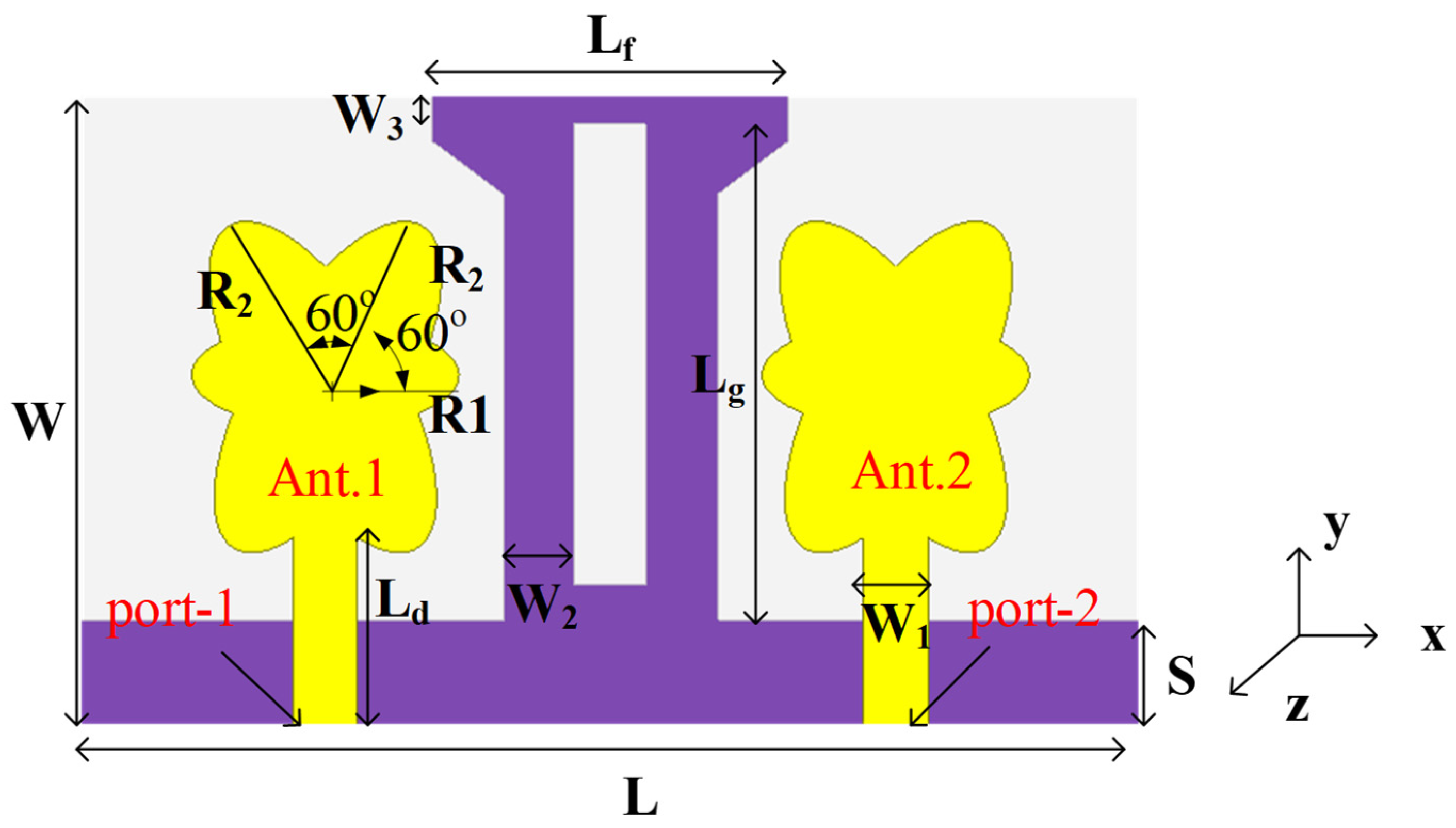
2.1. Antenna Geometry

Figure 1 depicts the topology of the proposed dual-port, flower-shaped UWB-MIMO antenna system, and Figure 2 shows the fabricated prototype. Compared with the antennas reported in [3,6,8,9,11,12,14], the MIMO antenna system proposed in this study has a smaller size of 30 × 18 mm2 (0.84λ × 0.50λ), and was designed on an FR4 substrate with 1.6 mm thickness (tanδ = 0.02 and εr = 4.4). Two similar flower-shaped radiating elements and a metal ground make up the overall antenna model. Each flower-shaped radiating element directly supplied by a microstrip line is made up of three elliptically shaped patches set above the substrate, each at an angle of 60 degrees from the others. Next, improved and inverted L-shaped branches with mirror symmetry and an I-shaped stub above L-shaped branches are added to create a T-like branch at the bottom of the substrate and above the rectangular floor, thereby establishing the proposed ground structure with a rectangular floor. The role of the T-like branching in this design is comparable to that of the ladder resonator proposed in [16], which will effectively block or absorb the surface current between the patch antenna elements at the operating frequency, thereby reducing the mutual influence. The specific design process and principle are described below. The parameters of the proposed dual-port UWB-MIMO antenna are listed in Table 1.

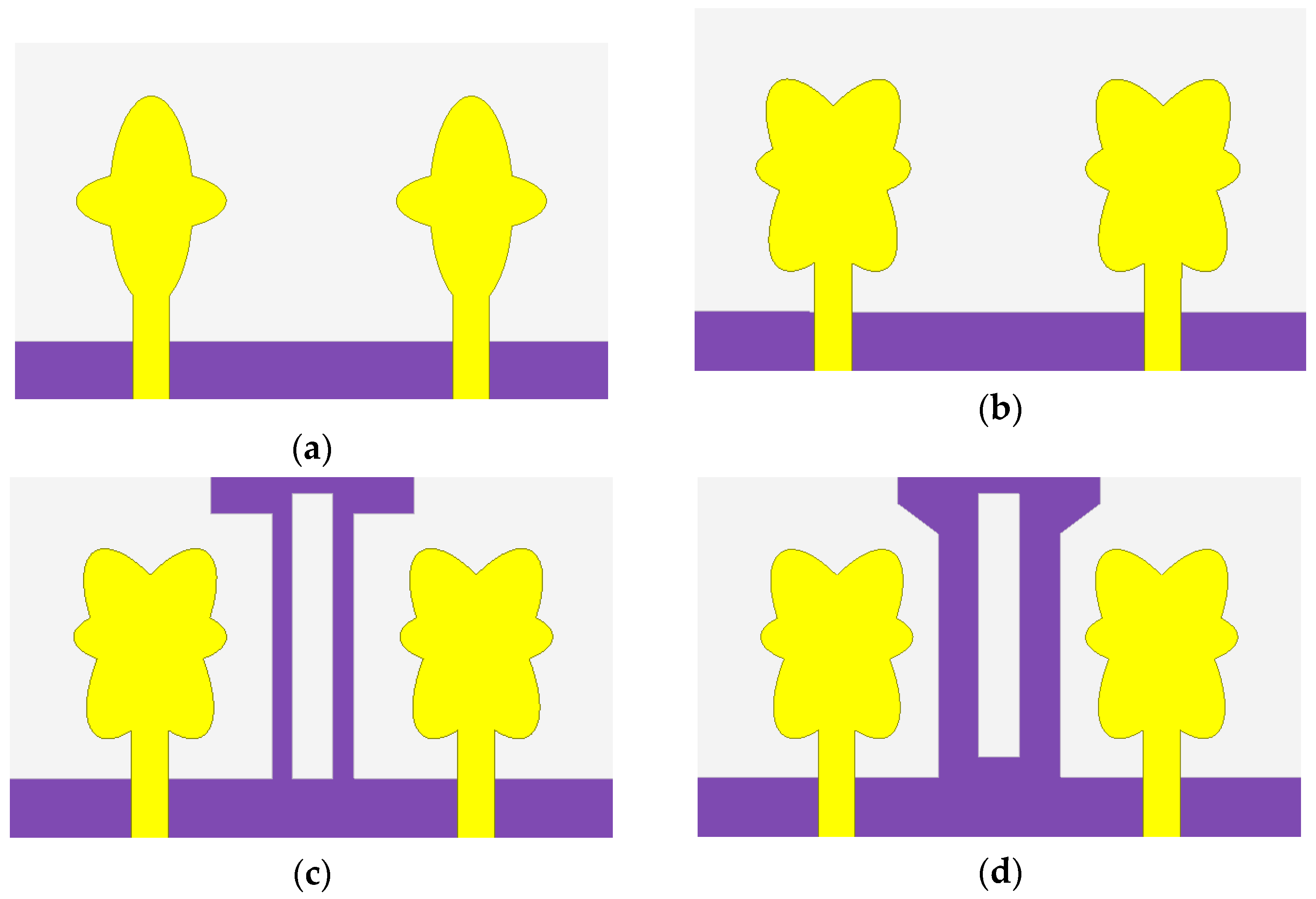
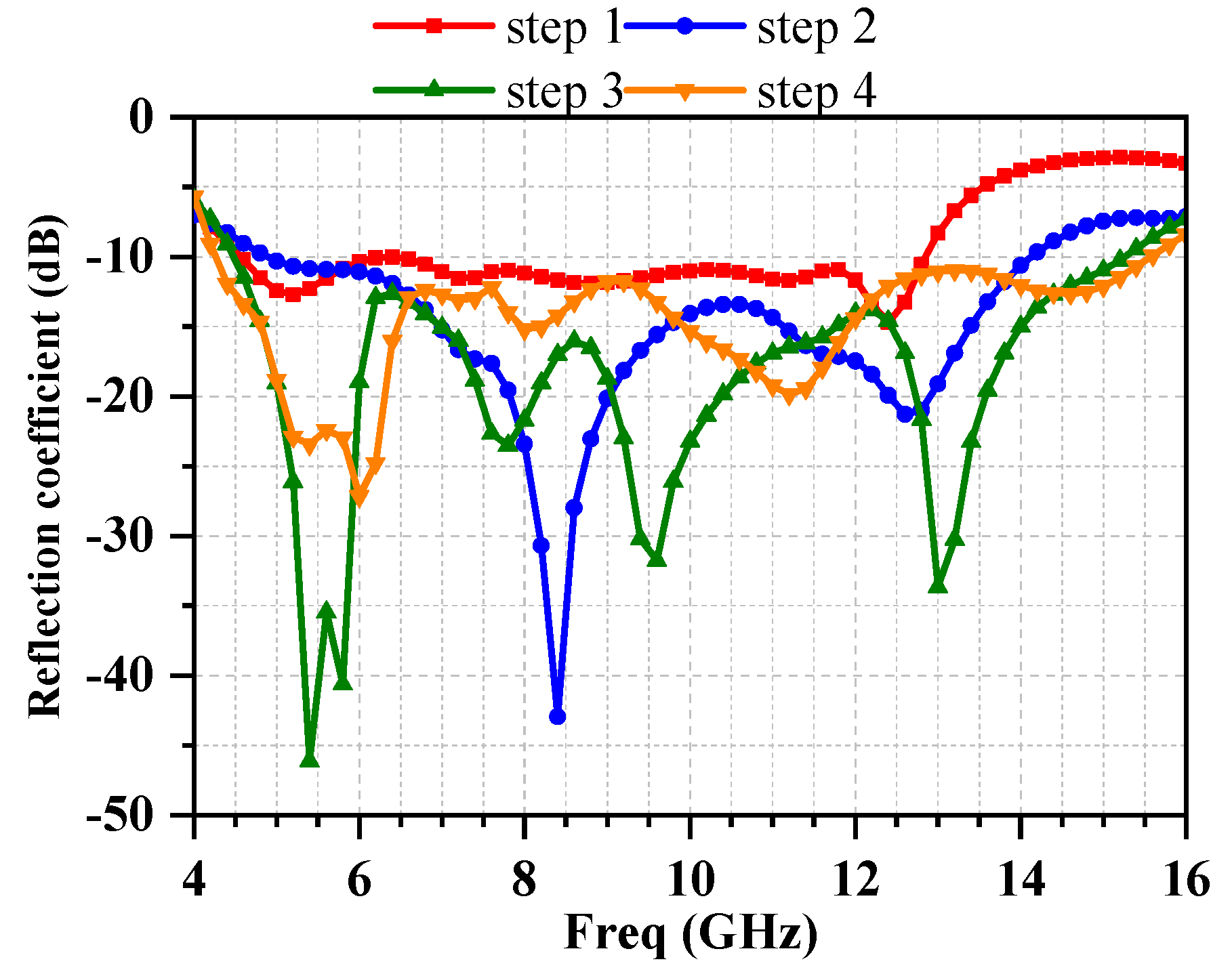
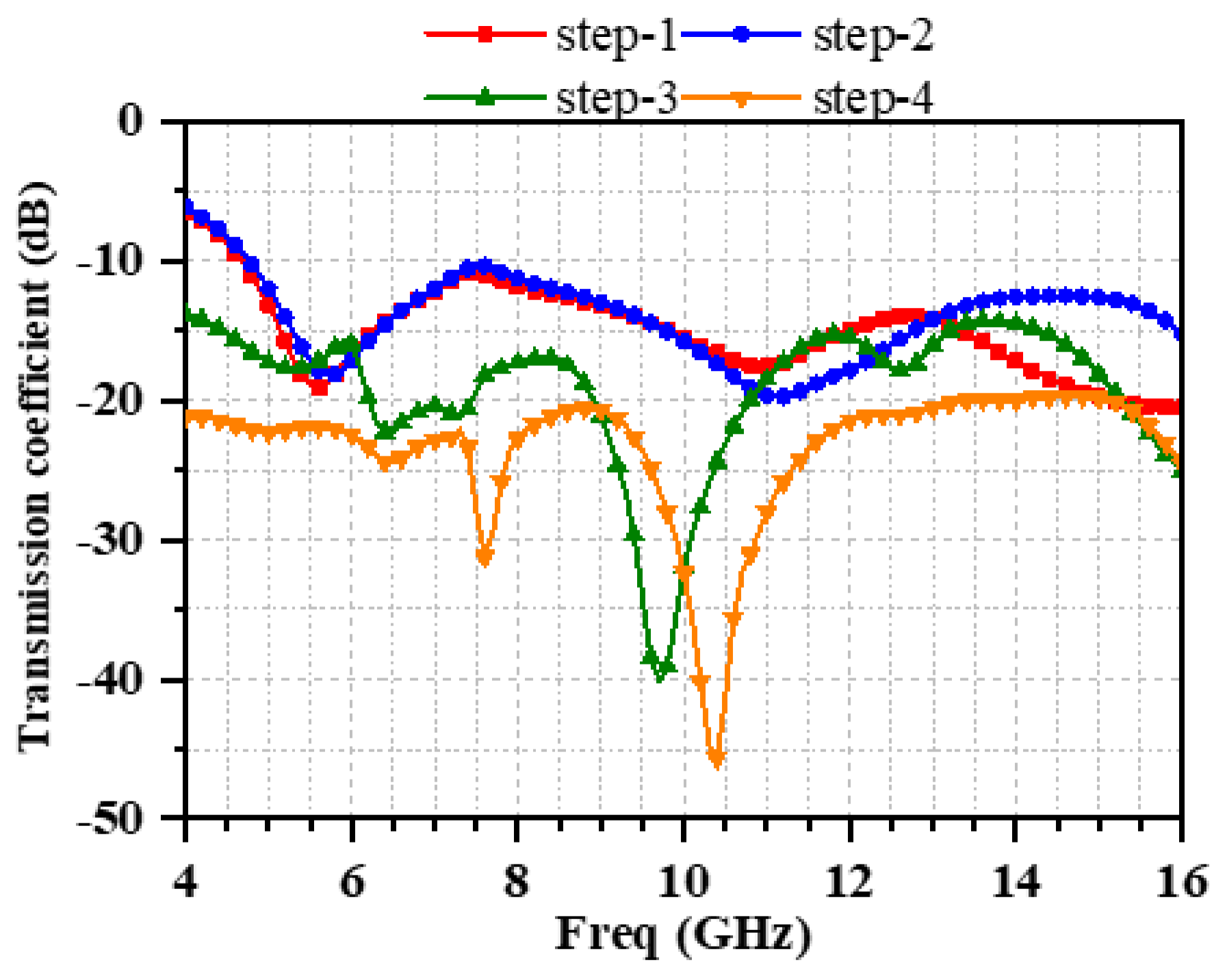
2.2. Design Evolution Stages of the MIMO Antenna

To examine the implications of different MIMO antenna configurations, the 50 Ω transmission line feed is utilized in combination with the fractional ground plane. The overall design procedure for the proposed UWB-MIMO antenna system is elaborated in Figure 3, and the MIMO system’s working principle, using its reflection coefficient and transmission coefficient curves, is presented in Figure 4 and Figure 5.
The radiating element in step 1 (Figure 3a) is made up of two mutually perpendicular elliptical patches and a microstrip line, along with a full rectangular ground at the bottom. Notably, the radiating element in this case is identical to the one proposed in [17], which is utilized for 5G communication. Although the antenna designed in step1 can cover 4.58–12.85 GHz, its reflection coefficient is poor, and the best value for S11 is only −15.2 dB, as shown in Figure 4. Meanwhile, the isolation between the antennas in the covered frequency range is less than 19 dB, since there is no decoupling structure involved, as illustrated in Figure 5.
Therefore, the radiating element is modified by merging three elliptically shaped patches in step 2, resembling a flower, but the ground structure is left unchanged. This antenna structure generates two resonant modes at 8.4 GHz and 12.8 GHz from its reflection coefficient, and the impedance-matching performance is improved. In the resonant modes, reflection coefficients are −43 and −21 dB, respectively, and the impedance bandwidth reaches 4.89–14.13 GHz. The transmission coefficient between the antennas, on the other hand, has not improved.
Progressively, in step 3, a horizontal I-shaped stub is placed above the inverted L-shaped branch to produce a T-like branch on ground, which improves the impedance matching and isolation compared with step 2. The antenna is stimulated into five resonant modes (5.38, 5.8, 7.8, 9.6, and 13 GHz), as shown by its reflection coefficient results, thus suggesting that the new T-like branch functions as a resonator, hence extending the bandwidth so that it spans between 4.48 and 15.26 GHz. From these results, we can see that the antenna’s bandwidth has been increased. Furthermore, the total reflection coefficient is lowered, indicating that the impedance-matching ability is improved. Due to the separation impact of the T-like branch on the antenna components, isolation is enhanced, reaching more than 14.2 dB. These findings suggest that the adoption of the T-like branch is important for boosting the bandwidth and isolation.
In the MIMO antenna system, increasing the independence between the antenna components has long been a desired aim. However, as a result, additional reductions in the correlation and improved isolation between the antenna components are required. Accordingly, we enhanced the shape of the metallic ground in step 4, which completed the design of the proposed UWB-MIMO system. To construct the final ground structure, the shape of the inverted L-shaped branch was slightly modified, i.e., the vertical width was extended and the triangular patches were proportionately cut out at the edges of the inverted L-shaped branches. The resonance frequencies stimulated in step 4 are shifted to the right compared with those of step 3, which are now 5.4, 6, 8, 11.2, and 14.6 GHz, respectively, as displayed in Figure 4. Although the reflection coefficient performance is worse than that of step 3, the design of step 4 still covers the frequency range of 4.3–15.63 GHz. More importantly, Figure 5 shows that the isolation in step 4 has been enhanced compared with that in step 3, reaching more than 20 dB, which suggests that the mutual coupling has been decreased. Essentially, these results imply that the improved ground structure makes a significant contribution toward improving the isolation.

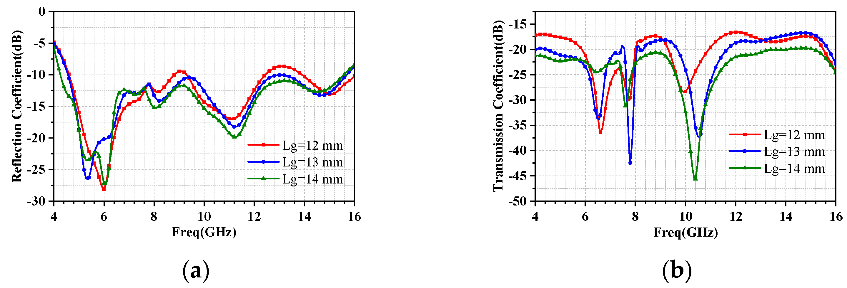
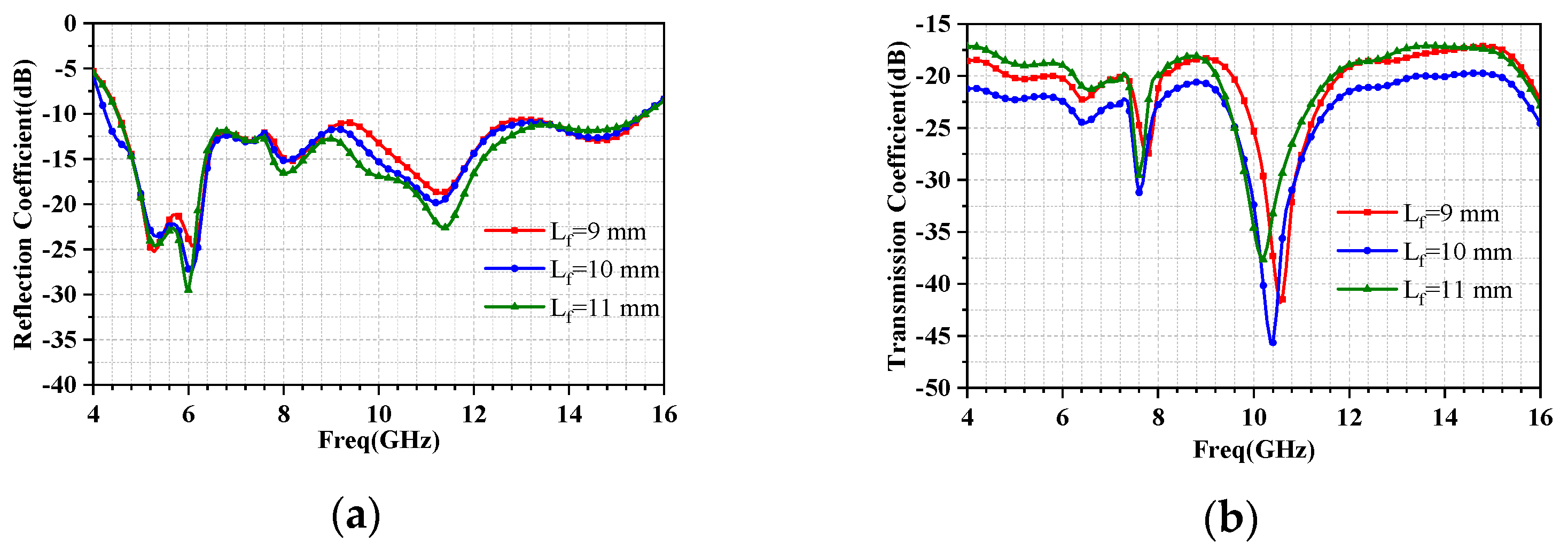
2.3. Parameter Analysis

The lengths of the modified T-like branches Lg and Lf have a dramatic impact on the UWB-MIMO system’s impedance-matching and isolation performance. Only the impact of these particular factors on system performance is examined, while other parameters are kept constant. The S-parameters for tuning Lg from 12 mm to 14 mm are illustrated in Figure 6. The impedance bandwidth is further improved when Lg changes from 12 mm to 14 mm, as shown in Figure 6a. Neither UWB features can be achieved when Lg has a value of 12 mm or 13 mm. Different values of Lg also exhibit various isolation effects in terms of their influence on isolation. Although the isolation effect is optimal overall when Lg is at 14 mm, as shown in Figure 6b, the transmission coefficient must be enhanced in the 6–8 GHz band region when Lg is at 14 mm. These results demonstrate that the S-parameters of the system are significantly influenced by the vertical length of the modified L-shaped ground branch (Lg), and it is best to select a value of 14 mm for Lg when taking into account the size of the system.
The simulated variation in characteristics of Lf from 9 mm to 11 mm are presented in Figure 7. As can be seen from Figure 7a, the effect of Lf on return loss is not very significant at these values, and all can achieve acceptable ultra-wideband properties. However, the effect of Lf on isolation is even more pronounced. As can be observed in Figure 7b, the optimal isolation effect is obtained when Lf is 10 mm, that is, when the I-shaped ground stub and modified L-shaped ground branch are exactly combined to form a T-like branch, which also confirms the authenticity of the proposed decoupling structure.

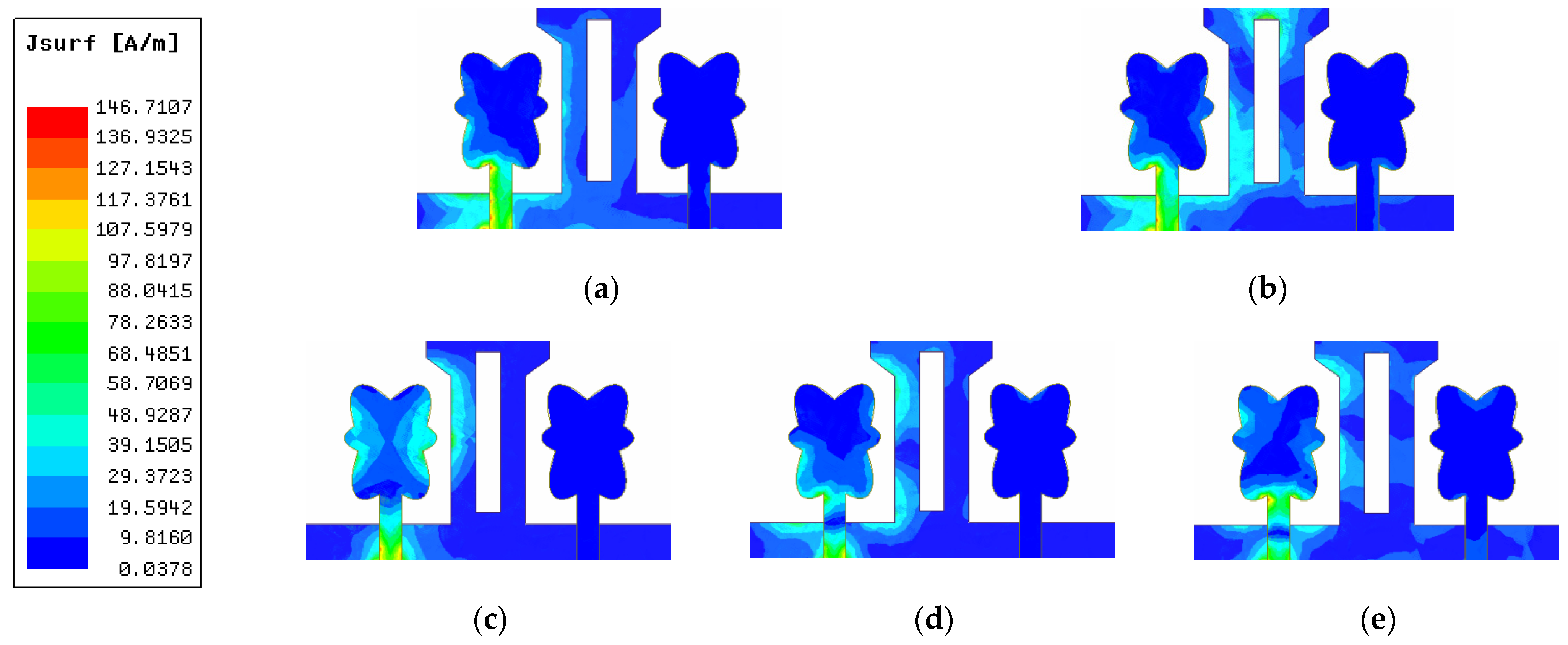
2.4. Current Distribution

Figure 8 presents the surface current distribution in the resonance modes, to visually emphasize the decoupling effect of ground plane geometry. In the proposed MIMO system, port 1 is stimulated, while port 2 is terminated with a 50 Ω matched load. When just port 1 is stimulated, the current is largely distributed on antenna 1 and its modified T-like branch on the same side, as shown in Figure 8, whereas the current distribution on the surface of antenna 2 is relatively weak. It can be deduced that current-absorbing effect of the improved ground branch successfully improves the port isolation between the two monopole antennas.

3. Results and Discussion

3.1. S-Parameter Results

HFSS and an Agilent N5247A vector network analyzer were used to simulate and measure the proposed UWB-MIMO antenna, and the results are provided in Figure 9. The measured S11 can cover 4.51–15.1 GHz, while S12 is below −15 dB, as shown in Figure 9. It is worthwhile to note that there are significant differences between the measured and simulated results of S12, especially in 6.5–7.5 GHz and 10–11 GHz bands, where some frequencies with a difference of more than 20 dB can be seen. Manufacturing and measurement errors might be responsible for the discrepancy between the simulated and measured S12 results, which does not affect the overall high-isolation performance of the system. From these findings, the proposed antenna offers a wide operation band with high isolation.

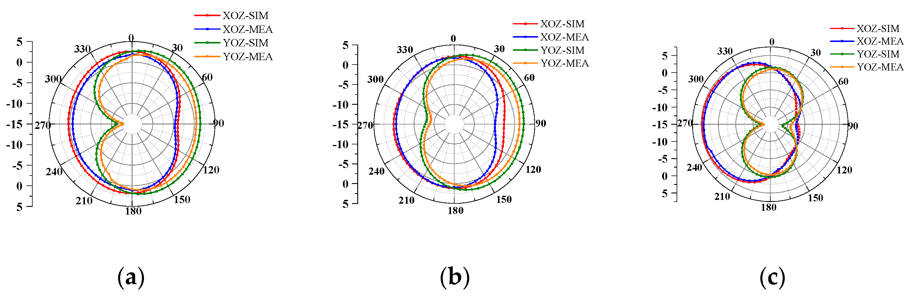
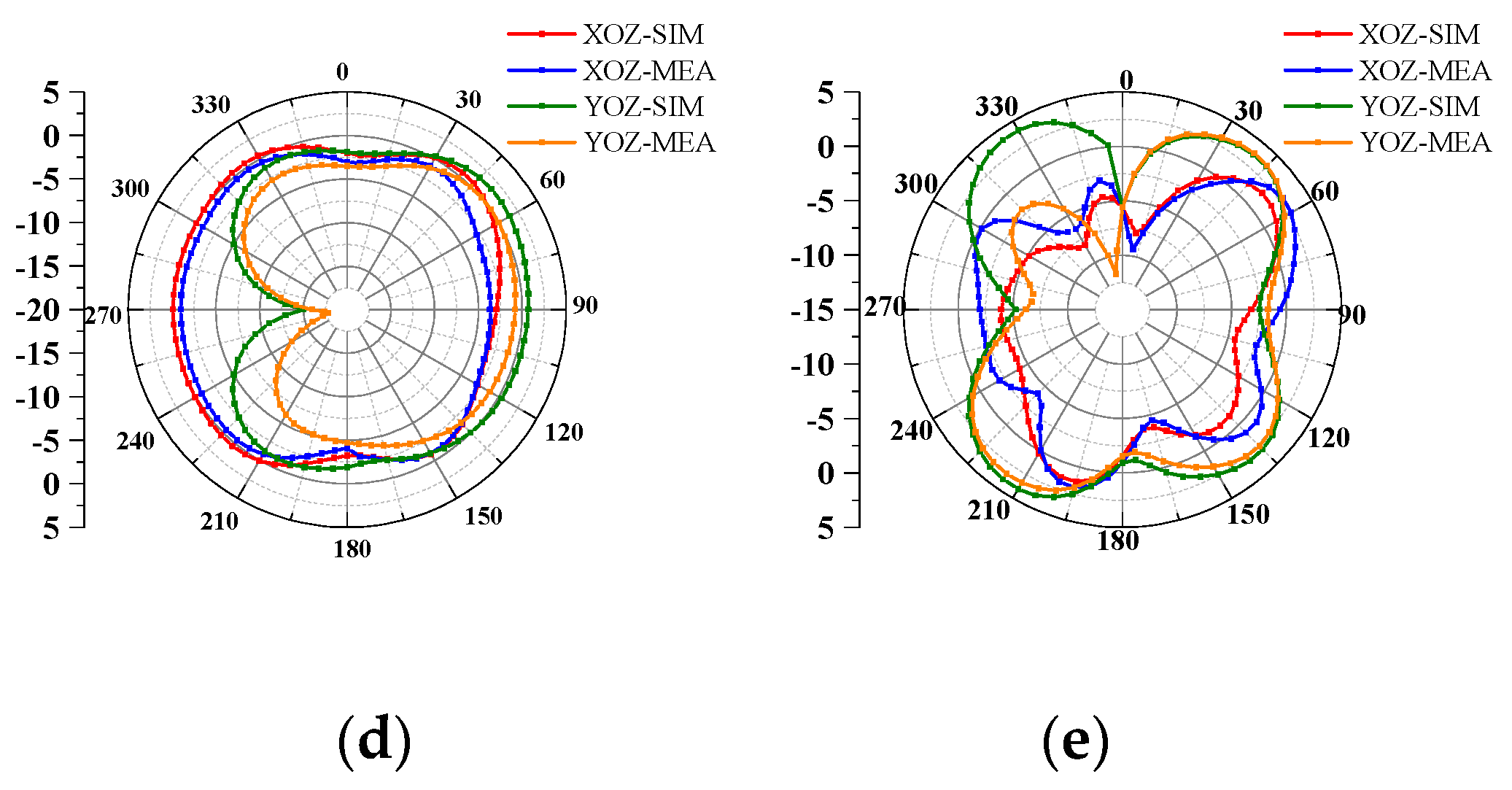
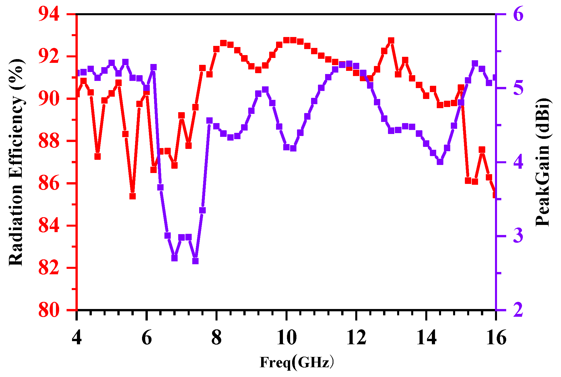
3.2. Far-Field Properties

The UWB-MIMO antenna was tested in an anechoic chamber for its radiation patterns, and the results are presented in Figure 10. By stimulating port 1 and terminating port 2 with a matched load, the corresponding radiation patterns were measured. It can be seen from Figure 10a,b that the antenna almost achieved omnidirectional radiation on both the XOZ plane and the YOZ plane at low frequencies (5.4 GHz and 6 GHz). At 8 GHz from (c), the radiation direction of the antenna on the XOZ surface was mainly distributed between 180° and 360°, and the maximum radiation gain reached 4.4 dB at approximately 255°, while on the YOZ surface, the maximum radiation direction was approximately 0° and 180°. At 11.2 GHz, the XOZ surface achieved almost omnidirectional radiation characteristics, while on the YOZ surface, the radiation gain obtained its maximum value at approximately 90°. However, at high frequency, it can be seen from Figure 10e that the radiation pattern of the XOZ plane was not as good as that of the YOZ plane. According to these results, the antenna had acceptable radiation characteristics on the XOZ (E-plane) and YOZ (H-plane) at frequencies of 5.4, 6, 8, 11.2, and 14.6 GHz, and the measured results are consistent with the simulated results.
The proposed MIMO antenna’s radiation efficiency and peak gain are shown on Figure 11. As the radiators of the proposed MIMO antenna were structured symmetrically, the following values are shown for only one radiator. The radiation efficiency varied from 85 to 93 percent, implying that the majority of the energy was radiated away. The maximum gain of a single antenna at 5.4 GHz was 5.35 dBi, whereas the peak gain values at 6.4–7.6 GHz were relatively low, in the range of 2.5–4 dBi. Throughout the whole operational frequency range, the proposed MIMO antenna showed a positive gain value. Based on the results described above, the proposed UWB-MIMO antenna system offers promising radiation features.

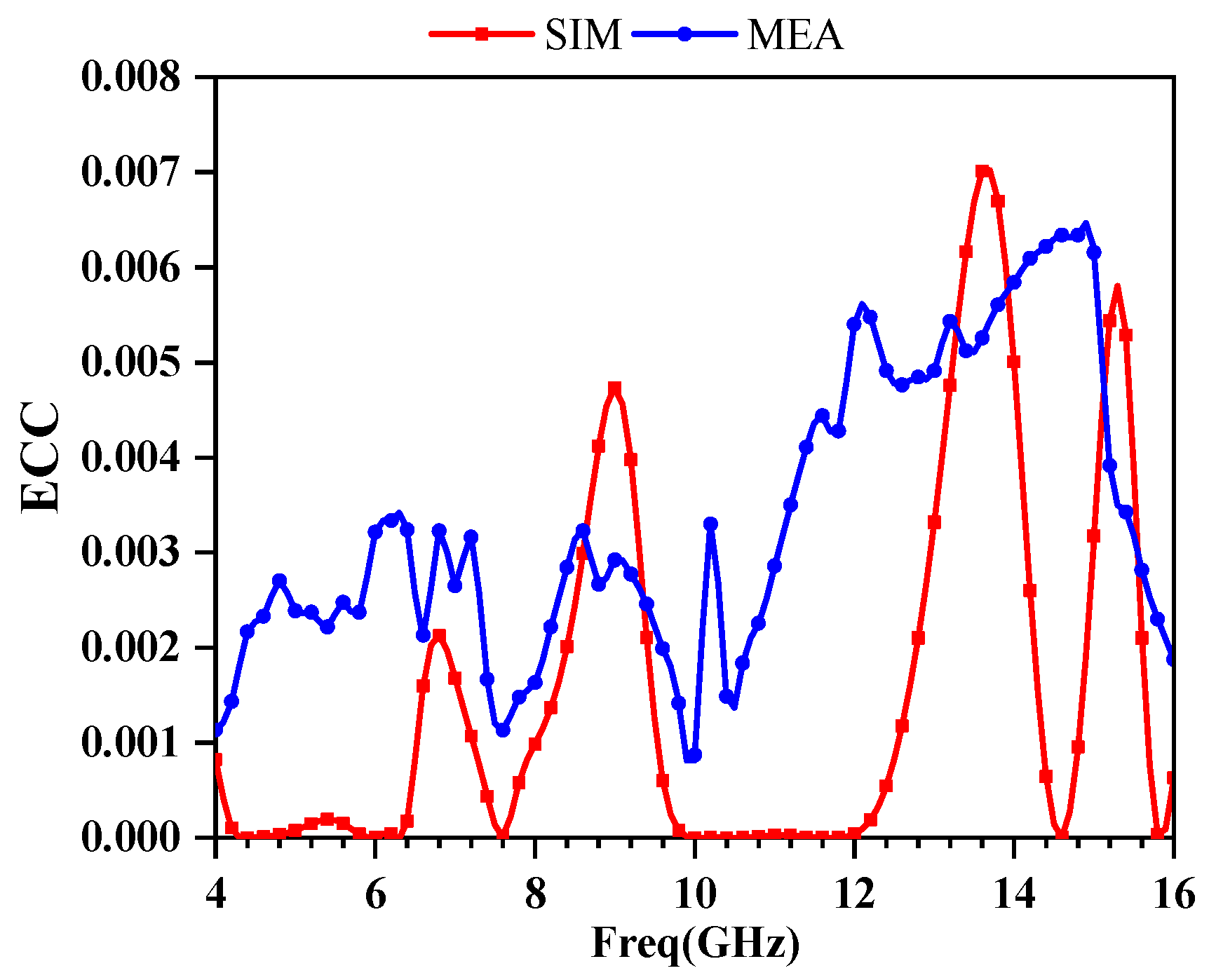
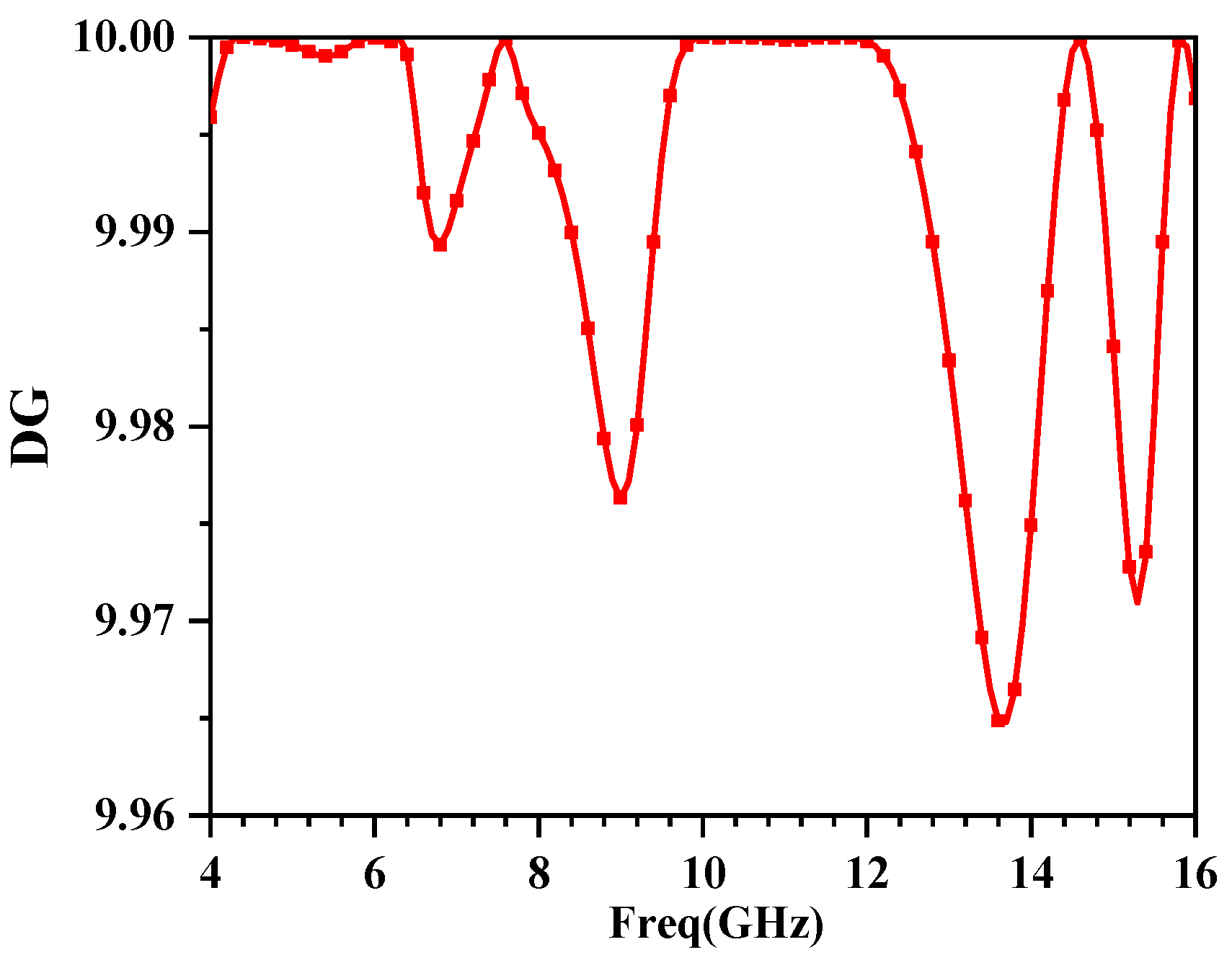
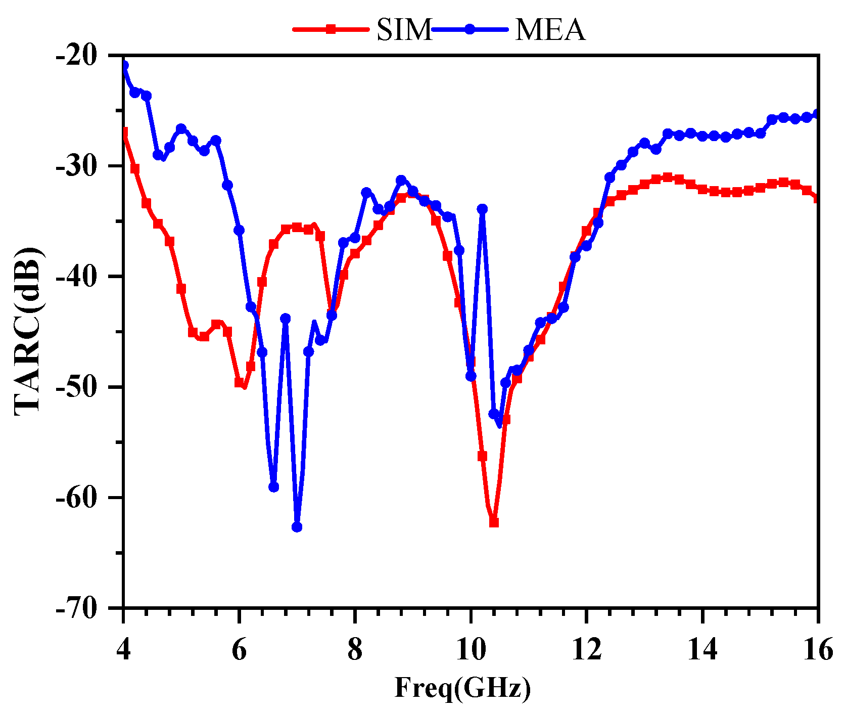
3.3. MIMO Performance

Different performance metrics of MIMO antennas, such as ECC (envelope correlation coefficient), DG (diversity gain), and TARC (total active reflection coefficient), should be examined to ensure their efficient operation.
The ECC value is a critical parameter for evaluating the performance of the radiation patterns of MIMO radiators. A lower ECC value indicates a lower effect on other antennas while working alone, and greater efficiency. To guarantee effective operation of each antenna, the specified ECC value of a MIMO system in wireless communication networks is generally less than 0.5 [18]. The ECC can be calculated from the S-parameters using Equation (1). The results of simulated and measured ECC are displayed in Figure 12, which shows an acceptable isolation performance.
ECC can be computed from the S-parameters using the following equation.
ECC = | S 11 * S 12 + S 21 * S 22 | 2 ( 1 | S 11 | 2 | S 21 | 2 ) ( 1 | S 22 | 2 | S 12 | 2 ) ,
Another key MIMO performance metric is DG, which describes how effective the diversity is. ECC is used to represent its value, which can be computed by Equation (2).
DG = 10 × 1 | ECC | ,
The value of DG, calculated from the S-parameters of the proposed MIMO antenna system, is shown in Figure 13. In the working frequency band, DG is larger than 9.96 dB, thereby indicating a strong MIMO diversity performance.
Furthermore, the statistic TARC is related to the total reflected power and total incident power, and it is used to assess the MIMO system’s effectiveness. TARC should ideally be zero, which indicates that the antenna receives all of the incident power [19]. TARC can be computed using Equation (3) for a two-port system. Figure 14 displays a comparison between simulated and measured TARC values, which reveals that TARC is less than −20 dB in operating frequency range.
TARC = ( S 11 + S 12 ) 2 + ( S 21 + S 22 ) 2 2 ,

4. Comparison with Existing Models

Table 2 compares the performance of the proposed structure with the performance of various previously published UWB-MIMO antenna configurations. In contrast with the other reported designs, the proposed UWB-MIMO antenna structure provides obvious benefits. As can be observed from the table, the proposed UWB-MIMO antenna structure outperforms all the other designs. The proposed candidate is ideally suited for numerous UWB wireless applications owing to its small size, moderate impedance bandwidth, strong isolation capability, low ECC, high gain, and relatively steady radiation efficiency.

5. Conclusions

A compact-sized, dual-port, flower-shaped UWB-MIMO antenna with high isolation is presented in this paper. Three elliptically shaped metal patches, located at 60 degrees from each other, were combined to form a flower-shaped radiating element. The adopted ground structure improvements, including two modified inverted L-shaped branches and an I-shaped stub, expand the impedance bandwidth by generating multiple resonance modes to cover the 4.3–15.63 GHz (relative bandwidth 113.4%) range, which is typically used for multi-standard wireless applications, such as 5G N79 (4.4–5 GHz), WLAN (5.15–5.35 GHz/5.72–5.825 GHz), 5G spectrum band (5.9–6.4 GHz), X-band for satellite communication (8–12 GHz), FSS (11.45–11.7 GHz/12.5–12.75 GHz), and Ku band (12–18 GHz). These improvements also effectively reduce the mutual coupling between the antennas by absorbing the current, thereby enhancing the isolation to more than 20 dB. In addition, the measured results suggest that the proposed antenna displays favorable radiation patterns, where the radiation efficiency is between 85% and 93%, while the peak gain ranges from 2.5–5.35 dBi. Moreover, the antenna also possesses acceptable values for ECC (<0.0075), DG (>9.96 dB), and TARC (<−20 dB), demonstrating that the proposed MIMO antenna is highly compatible with the UWB communication systems.

Author Contributions

Conceptualization, Z.W.; methodology, H.L. and M.Y.; software, W.M.; validation, W.M. and C.L.; investigation, W.N.; writing—original draft preparation, W.M.; writing—review and editing, H.L. and Z.W.; supervision, J.W. All authors have read and agreed to the published version of the manuscript.

Funding

This research was funded in part by the Anhui Provincial Natural Science Foundation under grant 2108085MF200, the Natural Science Foundation of Anhui Provincial Education Department under grant KJ2020A0307 and KJ2020A0768, the Academic Funding Project for Distinguished Top Talents of Colleges and Universities in Anhui Province under grant gxbjZD2021088, and the Graduate Innovation Fund of Anhui University of Science and Technology under grant 2021CX2070.

Institutional Review Board Statement

Not applicable.

Informed Consent Statement

Not applicable.

Data Availability Statement

The simulated and measured data used to support the findings of this study are included within the article.

Conflicts of Interest

The authors declare no conflict of interest.

References

  1. Mohamadzade, B.; Simorangkir, R.B.V.B.; Hashmi, R.M.; Lalbakhsh, A. A Conformal Ultrawideband Antenna With Monopole-Like Radiation Patterns. IEEE Trans. Antennas Propag. 2020, 68, 6383–6388. [Google Scholar] [CrossRef]
  2. Chandel, R.; Gautam, A.K.; Rambabu, K. Tapered Fed Compact UWB MIMO-Diversity Antenna with Dual Band-Notched Characteristics. IEEE Trans. Antennas Propag. 2018, 66, 1677–1684. [Google Scholar] [CrossRef]
  3. Chen, Z.J.; Zhou, W.S.; Hong, J.S. A Miniaturized MIMO Antenna With Triple Band-Notched Characteristics for UWB Applications. IEEE Access 2021, 9, 63646–63655. [Google Scholar] [CrossRef]
  4. Al-Gburi, A.J.A.; Ibrahim, I.M.; Zakaria, Z.; Abdulhameed, M.K.; Saeidi, T. Enhancing Gain for UWB Antennas Using FSS: A Systematic Review. Mathematics 2021, 9, 3301. [Google Scholar] [CrossRef]
  5. Bilal, M.; Shahid, S.; Khan, Y.; Rauf, Z.; Wagan, R.A.; Butt, M.A.; Khonina, S.N.; Kazanskiy, N.L. A Miniaturized FSS-Based Eight-Element MIMO Antenna Array for Off/On-Body WBAN Telemetry Applications. Electronics 2021, 11, 522. [Google Scholar] [CrossRef]
  6. Rahman, M.; NagshvarianJahromi, M.; Mirjavadi, S.S.; Hamouda, A.M. Compact UWB Band-Notched Antenna with Integrated Bluetooth for Personal Wireless Communication and UWB Applications. Electronics 2019, 8, 158. [Google Scholar] [CrossRef] [Green Version]
  7. Masoodi, I.S.; Ishteyaq, I.; Muzaffar, K.; Magray, M.I. A compact band-notched antenna with high isolation for UWB MIMO applications. Int. J. Microw. Wirel. Technol. 2020, 13, 634–640. [Google Scholar] [CrossRef]
  8. Khan, A.; Bashir, S.; Ghafoor, S.; Qureshi, K.K. Mutual Coupling Reduction Using Ground Stub and EBG in a Compact Wideband MIMO-Antenna. IEEE Access 2021, 9, 40972–40979. [Google Scholar] [CrossRef]
  9. Alsath, M.G.N.; Kanagasabai, M. Compact UWB Monopole Antenna for Automotive Communications. IEEE Trans. Antennas Propag. 2015, 9, 4204–4208. [Google Scholar] [CrossRef]
  10. Chithradevi, R.; Sreeja, B.S. A compact UWB MIMO antenna with high isolation and low correlation for wireless applications. In Proceedings of the 2017 IEEE International Conference on Antenna Innovations & Modern Technologies for Ground, Aircraft and Satellite Applications (iAIM), Bangalore, India, 24–26 November 2017; pp. 24–26. [Google Scholar]
  11. Wang, L.L.; Du, Z.H.; Yang, H.L.; Ma, R.Y.; Zhao, Y.C.; Cui, X.Q.; Xi, X.L. Compact UWB MIMO Antenna With High Isolation Using Fence-Type Decoupling Structure. IEEE Antennas Wirel. Propag. Lett. 2019, 18, 1641–1645. [Google Scholar] [CrossRef]
  12. Suresh, A.C.; Reddy, T. A Flower Shaped Miniaturized 4 × 4 MIMO Antenna for UWB Applications Using Characteristic Mode Analysis. Prog. Electromagn. Res. C 2022, 119, 219–233. [Google Scholar] [CrossRef]
  13. Wu, L.; Cao, X.; Yang, B. Design and Analysis of a Compact UWB-MIMO Antenna with Four Notched Bands. Prog. Electromagn. Res. M 2022, 108, 127–137. [Google Scholar] [CrossRef]
  14. Dalal, P.; Dhull, S.K. Design of triple band-notched UWB MIMO/diversity antenna using triple bandgap EBG structure. Prog. Electromagn. Res. C 2021, 113, 197–209. [Google Scholar] [CrossRef]
  15. Agarwal, S.; Rafique, U.; Ullah, R.; Ullah, S.; Khan, S.; Donelli, M. Double Overt-Leaf Shaped CPW-Fed Four Port UWB MIMO Antenna. Electronics 2021, 10, 3140. [Google Scholar] [CrossRef]
  16. Roshani, S.; Shahveisi, H. Mutual Coupling Reduction in Microstrip Patch Antenna Arrays Using Simple Microstrip Resonator. Wirel. Pers. Commun. 2022, 1–13. [Google Scholar] [CrossRef]
  17. Bait-Suwailam, M.M.; Almoneef, T.; Saeed, S.M. Wideband MIMO Antenna with Compact Decoupling Structure for 5G Wireless Communication Applications. Prog. Electromagn. Res. Lett. 2021, 100, 117–125. [Google Scholar] [CrossRef]
  18. Li, Y.X.; Sim, C.Y.D.; Li, Y.; Yang, G.L. High-Isolation 3.5 GHz Eight-Antenna MIMO Array Using Balanced Open-Slot Antenna Element for 5G Smartphones. IEEE Trans. Antennas Propag. 2019, 67, 3820–3830. [Google Scholar] [CrossRef]
  19. Bhatia, S.S.; Sharma, N. Modified Spokes Wheel Shaped MIMO Antenna System for Multiband and Future 5G Applications: Design and Measurement. Prog. Electromagn. Res. C 2021, 117, 261–276. [Google Scholar] [CrossRef]
  20. Banerjee, J.; Karmakar, A.; Ghatak, R.; Poddar, D.R. Compact CPW-fed UWB MIMO antenna with a novel modified Minkowski fractal defected ground structure (DGS) for high isolation and triple bandnotch characteristic. J. Electromagn. Waves Appl. 2017, 31, 1550–1565. [Google Scholar] [CrossRef]
  21. Khan, M.S.; Capobianco, A.D.; Asif, S.M.; Anagnostou, D.E.; Shubair, R.M.; Braaten, B.D. A compact CSRR enabled UWB diversity antenna. IEEE Antennas Wirel. Propag. Lett. 2016, 16, 808–812. [Google Scholar] [CrossRef]
  22. Zhao, Y.; Zhang, F.S.; Cao, L.X.; Li, D.H. A compact dual band-notched MIMO diversity antenna for UWB wireless applications. Prog. Electromagn. Res. C 2019, 89, 161–169. [Google Scholar] [CrossRef] [Green Version]
  23. Ren, J.; Hu, W.; Yin, Y.; Fan, R. Compact printed MIMO antenna for UWB applications. IEEE Antennas Wirel. Propag. Lett. 2014, 13, 1517–1520. [Google Scholar]
  24. Zamir, W.; Kumar, D. A compact 4 × 4 MIMO antenna for UWB applications. Microw. Opt. Technol. Lett. 2016, 58, 1433–1436. [Google Scholar]
  25. Kang, L.; Li, H.; Wang, X.H.; Shi, X.W. Miniaturized band-notched UWB MIMO antenna with high isolation. Microw. Opt. Technol. Lett. 2016, 58, 878–881. [Google Scholar] [CrossRef]
Figure 1. The proposed dual-port, flower-shaped UWB-MIMO antenna system structure.
Electronics 11 02190 g001
Figure 2. Fabricated prototype of the proposed dual-port, flower-shaped UWB-MIMO antenna: (a) front view, (b) back view.
Electronics 11 02190 g002
Figure 3. Evolution of the design process of UWB-MIMO system: (a) step 1, (b) step 2, (c) step 3, (d) step 4 (proposed MIMO system).
Electronics 11 02190 g003
Figure 4. Comparison of reflection coefficients of 4 proposed UWB-MIMO antenna designs.
Electronics 11 02190 g004
Figure 5. Comparison of transmission coefficients of 4 proposed UWB-MIMO antenna designs.
Electronics 11 02190 g005
Figure 6. Simulated S-parameters for tuning Lg: (a) reflection coefficient, (b) transmission coefficient.
Electronics 11 02190 g006
Figure 7. Simulated S-parameters resulting from the tuning of Lf: (a) reflection coefficient, (b) transmission coefficient.
Electronics 11 02190 g007
Figure 8. Surface current distribution when port 1 is stimulated at (a) 5.4 GHz, (b) 6 GHz, (c) 8 GHz, (d) 11.2 GHz, (e) 14.6 GHz.
Electronics 11 02190 g008
Figure 9. Simulated and measured S-parameters.
Electronics 11 02190 g009
Figure 10. Simulated and measured far-field patterns on XOZ and YOZ planes at (a) 5.4 GHz, (b) 6 GHz, (c) 8 GHz, (d) 11.2 GHz, and (e) 14.6 GHz.
Electronics 11 02190 g010aElectronics 11 02190 g010b
Figure 11. Calculated radiation efficiency and peak gain.
Electronics 11 02190 g011
Figure 12. Simulated and measured ECC.
Electronics 11 02190 g012
Figure 13. Calculated DG.
Electronics 11 02190 g013
Figure 14. The comparison of simulated and measured TARC.
Electronics 11 02190 g014
Table 1. Dimensions of the proposed MIMO antenna structure (f = 4 GHz).
ParameterDimension Value (mm)
LLength of MIMO antenna 30 (0.84λ)
WWidth of MIMO antenna 18 (0.50λ)
LdLength of microstrip feed line5.416 (0.15λ)
W1Width of microstrip feed line1.8 (0.05λ)
R1Radius of ellipse 13.75 (0.10λ)
R2Radius of ellipse 25.25 (0.15λ)
SWidth of rectangular metallic ground3 (0.084λ)
LgVertical length of modified L-shaped ground branch14 (0.39λ)
W2Width of modified L-shaped ground branch2 (0.056λ)
LfLength of I-shaped ground stub10 (0.28λ)
W3Width of I-shaped ground stub1 (0.028λ)
Table 2. Comparison of several reported UWB-MIMO antennas.
RefSize (mm2)Ports NumberBandwidth (GHz)Isolation (dB)Decoupling
Technique
ECCRadiation Efficiency (%)Gain
(dBi)
[3]34 × 3442.5–1215Perpendicular Placement and a Parasitic Strip<0.05>752.5–5.5
[8]26 × 3123.1–1125Ground Stub and EBG<0.01>700–5.5
[9]42 × 2423.1–10.915Vertical Placement<0.2>750–3.5
[12]40 × 4043.1–1418Swastika-shaped Stub<0.012>895.5
[20]42 × 2723.1–11.515Defected Ground Structure (DGS)<0.005>750–2
[21]29 × 2323.0–12.015Inverted L-shaped Stub and CSRR<0.15>824.7
[22]26 × 2822.9–10.815T-shape Stub<0.08Not Given1.6–4
[23]32 × 3222.9–1215Placed Perpendicularly<0.04>601.7–4.2
[24]35 × 3543.8–1515Ground Stubs<0.07>703–5
[25]28 × 2222.9–11.820H-shape Slot<0.03Not Given1.4–3.7
This work30 × 1824.3–15.6320Ground Branch<0.007585–932.5–5.35
Publisher’s Note: MDPI stays neutral with regard to jurisdictional claims in published maps and institutional affiliations.

