Article

Research on an Optimized Overmodulation Strategy Based on Rectifier of Indirect Space Vector of Matrix Converter

College of Electrical Engineering, Navel University of Engineering, JieFang Road 717, Wuhan 430030, China
*
Author to whom correspondence should be addressed.
Electronics 2022, 11(13), 2009; https://doi.org/10.3390/electronics11132009
Submission received: 17 May 2022 / Revised: 10 June 2022 / Accepted: 10 June 2022 / Published: 27 June 2022
(This article belongs to the Special Issue Advancement in Power Electronics and Control)

Abstract

:
Output performances including voltage error and THD effected by hexagon vector and basic vector with traditional indirect space vector overmodulation method are analyzed, and an improved overmodulation method based on input current vector synthesized is presented. Simulation and experimental results are carried out to validate the effectiveness of the proposed method. Simulation results indicate that the proposed input current vector-synthesized overmodulation strategy has better output performances. The experimental results verify that theoretical analysis is right and the proposed method is feasible.

1. Introduction

Matrix converter (MC) achieves direct AC-AC power conversion without intermediate energy storage elements. The MC features high power density and high efficiency [1,2,3], which has been demonstrated from both academia and industry. Therefore, it has been widely considered a promising topology to the widely used AC-DC-AC converter and back-to-back PWM converter. The prosperous researches of MC have lasted for nearly 50 years, covering from new topologies [4,5], modulation strategies [6,7,8,9], commutation strategies [10,11], applications [12,13], and etc. [14,15,16,17].
However, a major drawback of MC is that the maximum voltage transfer ratio (VTR) achieved by the traditional linear modulation strategy is only 0.866. This has inhibited the MC as a common solution for variable speed AC drive systems. An effective solution is applying the overmodulation strategy, which has gained attention worldwide. Generally, overmodulation methods proposed for the traditional voltage source converters can be handily extended to the MC [18,19,20]. In [18], the VTR of the MC by using double mode overmodulation method can be improved to 1, which are verified by simulations. In [19], an overmodulation strategy based on output voltage fundamental amplitude linear control is presented. This method is easy to implement, but the total harmonic distortion (THD) of output voltage is relatively high. In [20], the overmodulation strategy for the two-stage MC is realized from both of the rectifier and inverter simultaneously, and the VTR with the proposed can be achieved to be 1; however, it generates significant input current harmonic and output voltage error while the reason is not analyzed in detail. The overmodulation strategy based on double SVPWM without using zero vector is proposed in [21]. The output voltage vector angle is modified in different modes, and thus it could achieve smaller output voltage error at the cost of high computational burden. Two improved SVPWM strategies based on the linear superimposition principle are proposed by modifying the magnitude of the reference output voltage, and input current vectors are proposed in [22]. The overmodulation performance under input unbalance conditions is evaluated using the double Fourier integral transform approach. Two novel space vector pulse width modulation strategies based on the linear superimposition principle are presented by modifying the magnitude of the reference output voltage and the reference input current vectors, and the harmonic characteristics of the input current and output voltage are quantitatively analyzed by employing the double Fourier integral transform method [23]. A novel multimode space vector overmodulation strategy based on minimum principle of output voltage and input current harmonic by dividing over modulation method into three modes is presented in [24]; the output voltage minimum-phase error, input current minimum-magnitude-error (MME), and output voltage MME overmodulation strategies are realized in overmodulation mode I, II, and III. The VTR of the MC is improved to 1.05 and the output low-frequency harmonics in the overmodulation mode I and mode II are reduced, but it needs a large number of calculations. In [25], an overmodulation strategy based on multi-orbit vector weighted is studied, and the VTR of the MC is improved to be 1.05 by using different vectors to synthesize output voltage vector. In [26], a space vector overmodulation method for ultra-sparse MC based on the maximum output voltage vector is proposed by changing the modulation method of the inverter stage. On the basis of the VTR to 1, the VTR of overmodulation I is extended from 0.909 to 0.954 when the low-frequency harmonic component is below 3%. An overmodulation method based on direct SVPWM method is discussed in [27], and the maximum VTR is 0.985 at the expense of high distortions in the source current. In [28], an overmodulation method based on predictive control is proposed to enhance the maximum VTR of the CMC, and an automatic adjusting method of the used weighting factor is presented. The maximum VTRs are higher than 0.98 for different output frequencies by searching the optimal switch combination in the whole switching state range. In [29], an improved overmodulation strategy based on multi-orbit vector weighted is presented to achieve good performances of the MC. However, both of the methods in [28,29] need a large number of calculations and system stability is degraded.
From the above analysis of existing studies, it can be known that the overmodulation strategies of the MC are mainly realized by optimizing the SVPWM of the inverter stage, and there is little literature on the overmodulation method of rectifier stage, which results in high harmonic of input current. Therefore, in order to improve the voltage transfer ratio of matrix converter and reduce the harmonic content of input current, this paper studies the overmodulation strategy of rectifier stage.
This paper is organized as follows: firstly, the topology and principal of the MC is introduced; secondly, the input current vector in the traditional over modulation strategy of the VSR of the MC is analyzed; thirdly, to improve the input and output performances of the MC with VTR higher than 0.866, an optimal overmodulation strategy of the VSR is proposed; finally, the input and output performances of the MC with the traditional and proposed overmodulation strategies are simulated and experimented, and then the conclusion of the paper is drawn.

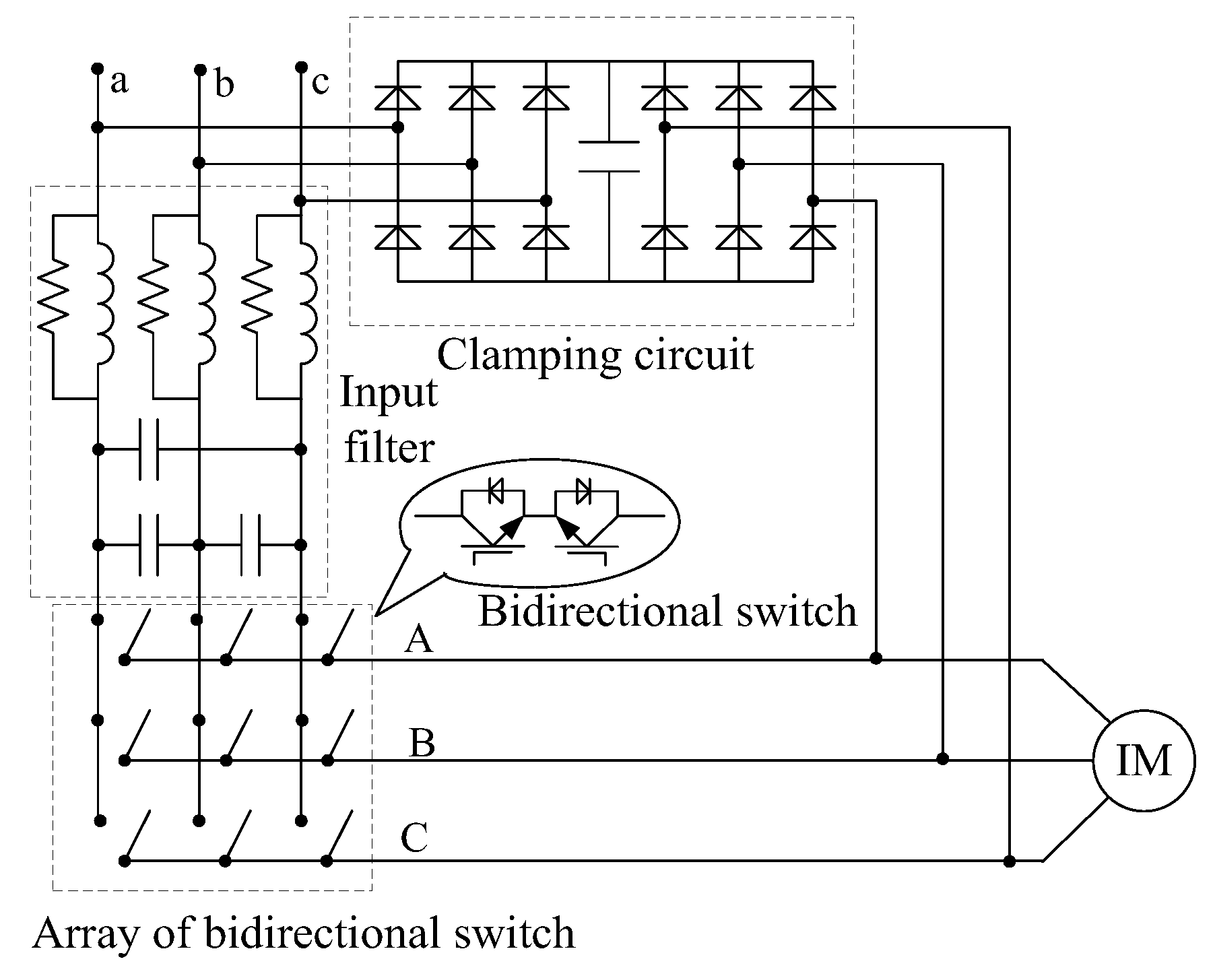
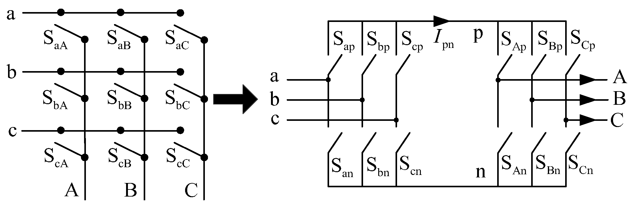
2. The Topology of the MC

The topology structure of direct three-phase to three-phase MC is shown in Figure 1 (a, b, c are three-phase input voltage nodes, A, B, C are three-phase output voltage nodes), including the input filter, bidirectional AC switches and clamping circuit [12]. The input filter is used to improve input current quality with restraining high-frequency harmonics. The bidirectional AC switches are configured as a 3 × 3 matrix, which is used to synthesize referenced output voltage and input current [12]. The clamping circuit is used for over-voltage protection and bidirectional switch.
MC can be seen as a fictitious AC-DC-AC structure, which is shown as in Figure 2 right side. The fictitious AC-DC-AC contains two parts, input side can be seen as a voltage source rectifier (VSR), and output side can be seen as a voltage source inverter (VSI). The switch configures in the MC can be obtained by using the equivalent structure to the fictitious AC-DC-AC converter [12].
The MC Modulation index m, VSI Modulation index mv, and VSR Modulation index mc, can be obtained by using the relation between VSR and VSI circuit in [1].
{ m v = 3 U o m U d c ( 0 m v 1 ) m c = I i m I d c ( 0 m c 1 ) M = m v m c = U o m ( 3 / 2 ) U i m c o s ϕ i ( 0 m 1 )
where, Udc, Idc are fictitious DC voltage and current of the VSR, respectively [21]. Uim, Iim, Uom are input voltage vector amplitude, input current vector amplitude, and output voltage vector amplitude, respectively. φi is input power factor angle, and M is the modulation index of the MC.

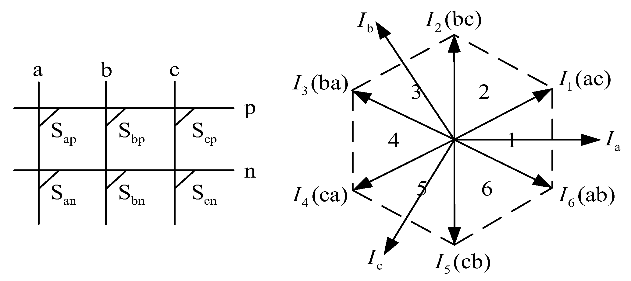
3. Input Current Vector Optimal Modulation Strategy of the VSR of the MC

3.1. Traditional Modulation Strategy of Input Current Vector

The principal of referenced input current vector Iin synthesized in the VSR is shown as Figure 3. It can be seen that there are six basic vectors Ix (x = 1~6) and two zero vectors, and another two vectors Isin and Ihex, which are the inscribed circle vector and hexagon vector, respectively. They can be expressed as follows [12]
{ I x = 2 I d c 3 e j ( ( x 1 ) π 3 + π 6 ) , x = 1 ~ 6 I s i n = I d c e j θ i I h e x = I d c c o s ( θ i ( x 1 ) π 3 π 6 ) e j θ i
In order to improve VTR of the MC, the input current vector Iin is generally defined as the hexagon vector Ihex, and it can be expressed as follows in [12]
I i n = I h e x
The VTR of the MC is improved, which will lead to big output voltage error and high input current THD in [28].

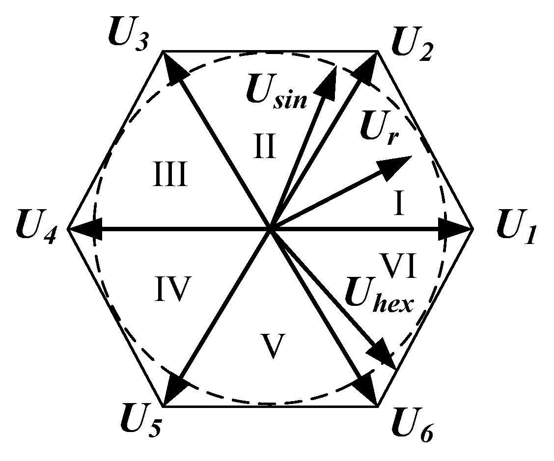
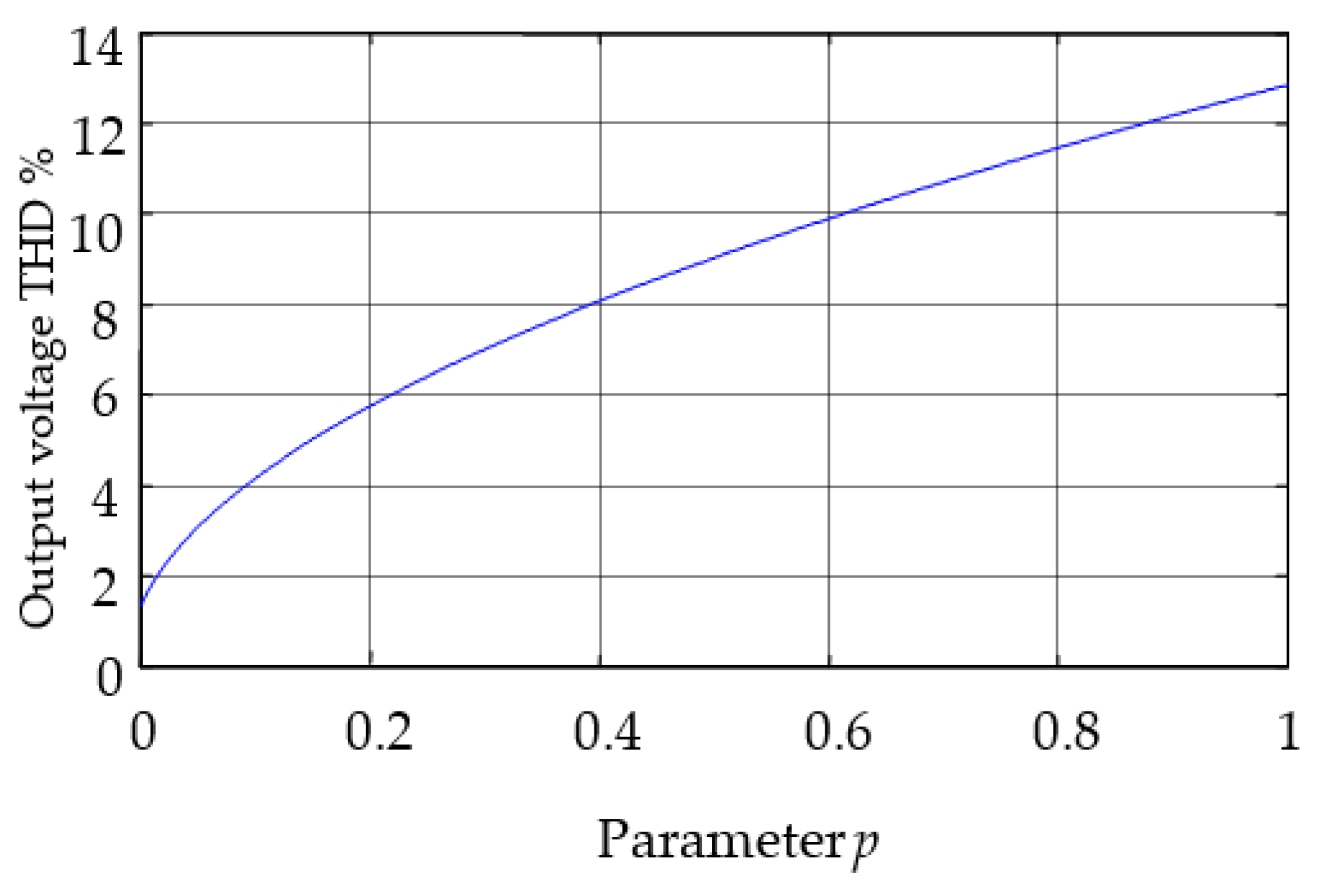
3.2. The Reason for the Big Output Voltage Error and High Input Current THD

The traditional overmodulation method in the VSI of the MC divides overmodulation region into two parts [28]. In overmodulation region I, 0.866 < M ≤ 0.909, output voltage vector Ur is synthesized by the hexagon vector Uhex and inscribed circle vector Usin and is shown as Figure 4 and can be expressed as follows.
U r e f = ( 1 p ) U s i n + p U h e x
where
p = M 0.866 0.909 0.866
From Equation (4), output voltage fundamental amplitude Uom and output voltage THD can be obtained as follows, respectively.
U o m = 0.5773 + 0.0286 p
THD = 2 π ( 0.0013 p 2 + 0.03 p + 0.2618 ) 0.5 ( 0.5773 + 0.0286 p ) 2 ( 0.5773 + 0.0286 p ) 2
The output voltage THD that varies with p is shown in Figure 5. From Equation (6) and Figure 5, it can be known and seen that both of output voltage fundamental amplitude and THD increased when p increased [28].
The input current vector synthesized principal is the same as the output voltage vector of the VSI. The input current vector is synthesized only by the hexagon vector Ihex, leading to big output voltage error and high input current THD of the VSR.

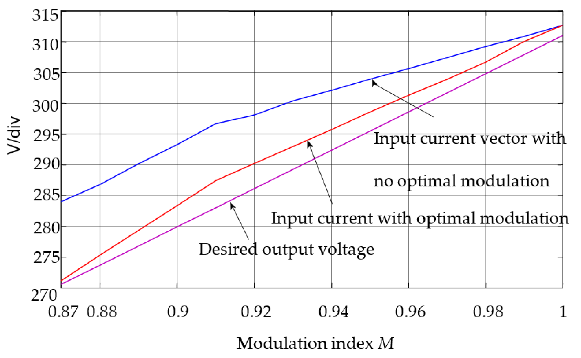
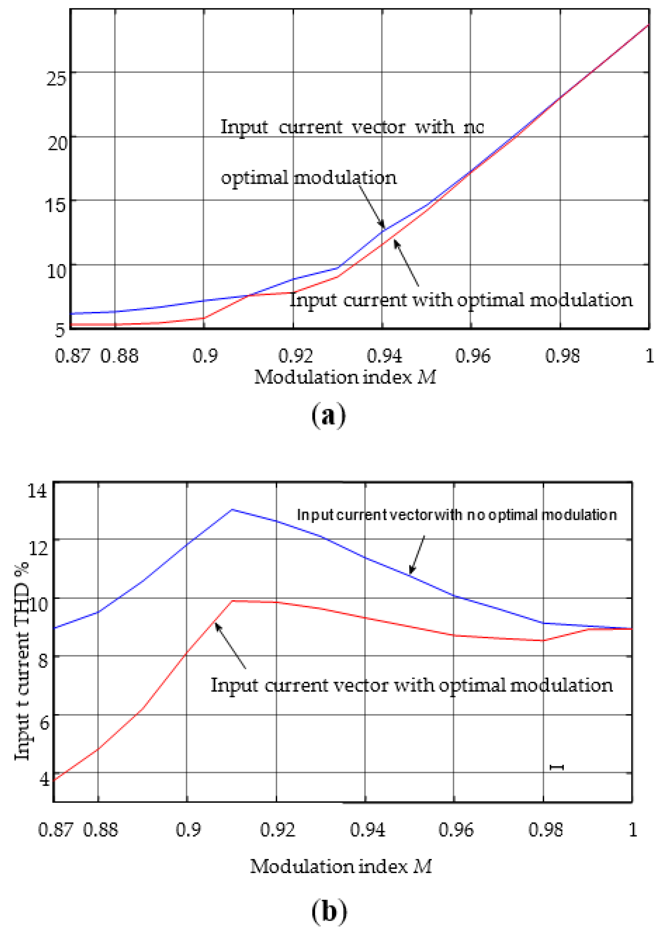
3.3. Input Current Vector Synthesized Optimal Modulation Strategy

To overcome the problems of big output voltage error and high input current THD with the input current vector rotating along the hexagon vector (it is defined as no optical modulation strategy), an optimized modulation strategy where the input current vector is synthesized by the hexagon vector and the inscribed vector is proposed. Compared with no optimized modulation strategy, the proposed strategy can decrease the output voltage error and input current THD by adjusting the weight of the hexagon vector in the input current vector.
Defining parameter p as follows:
p = M 0.866 1 0.866
The input current vector is synthesized by the hexagon vector Ihex and the inscribed vector Isin as follows:
I i n = ( 1 p ) I s i n + p I h e x
Assuming that the input current vector located in Section 2, the working time dα and dβ of basic vectors I1 and I2 are calculated as follows:
d α I 1 + d β I 2 = I i n
Combining Equations (2), (9) and (10), dα and dβ can be obtained as follows:
d α = [ 1 p + p cos ( π 3 θ i ) ] sin ( π 2 θ i ) d β = [ 1 p + p cos ( π 3 θ i ) ] sin ( θ i π 6 ) , θ i ( π 6 , π 2 ]
When the input current vector is located in other sectors, the working time dα and dβ can be calculated as Equation (9). When the input current vector is located in different sectors, duty ratio of each switch of the MC can be obtained by using the equivalent structure of the fictitious AC-DC-AC converter, including the VSI and VSR modulation strategy. Many papers have discussed how to calculate the duty ratio of each switch of the MC, and it will not be discussed anymore in the paper [21].

4. Simulation and Experiments

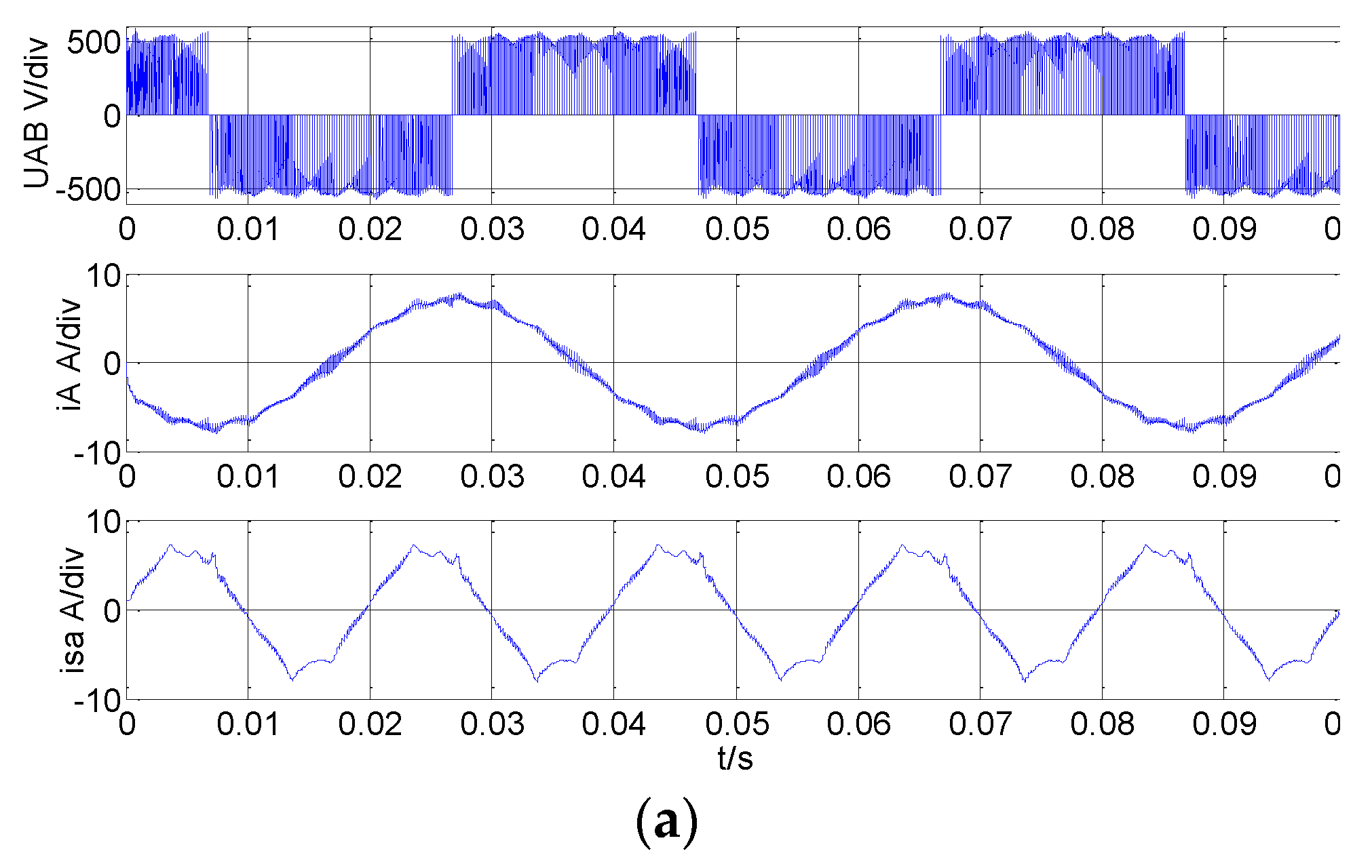
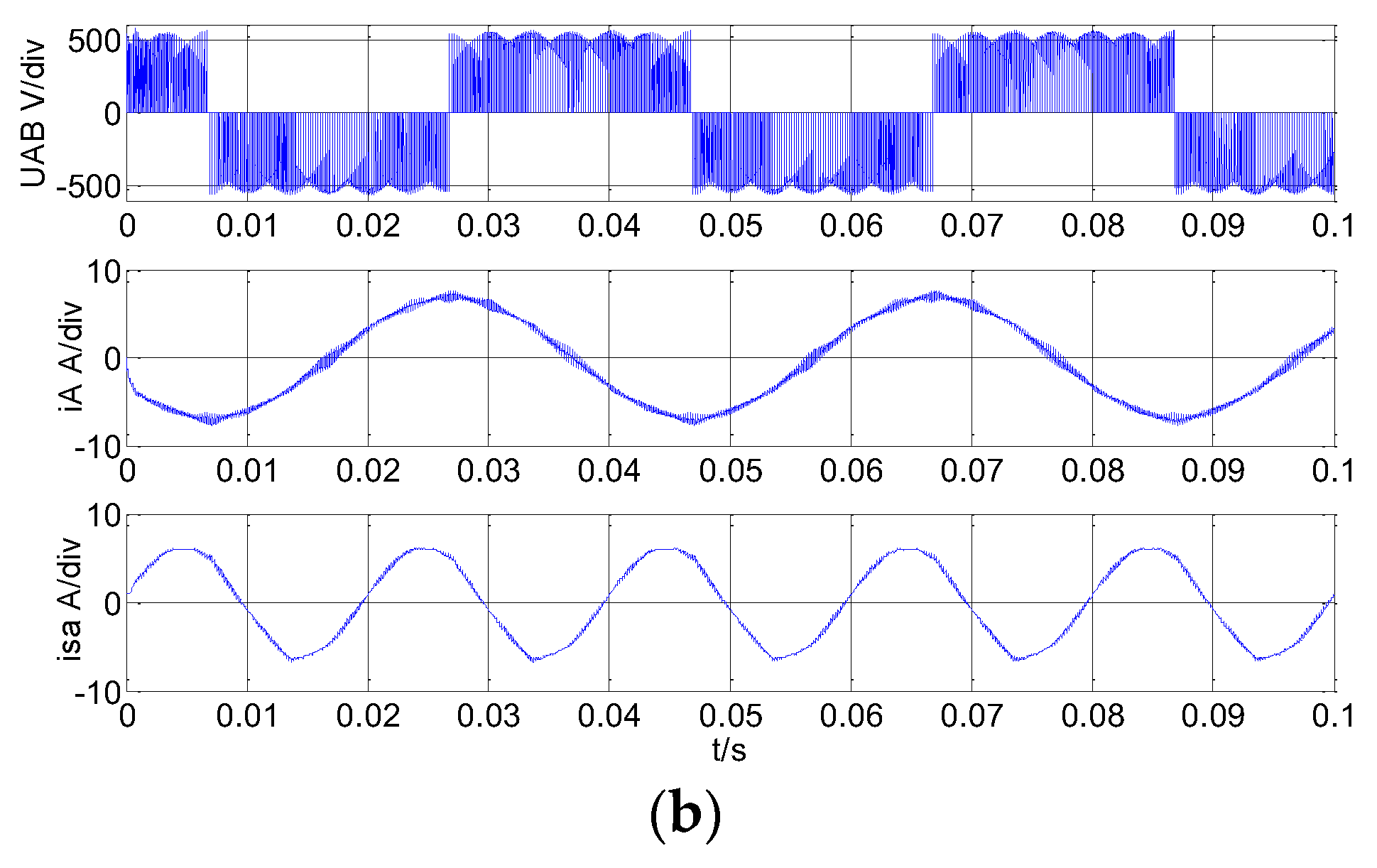
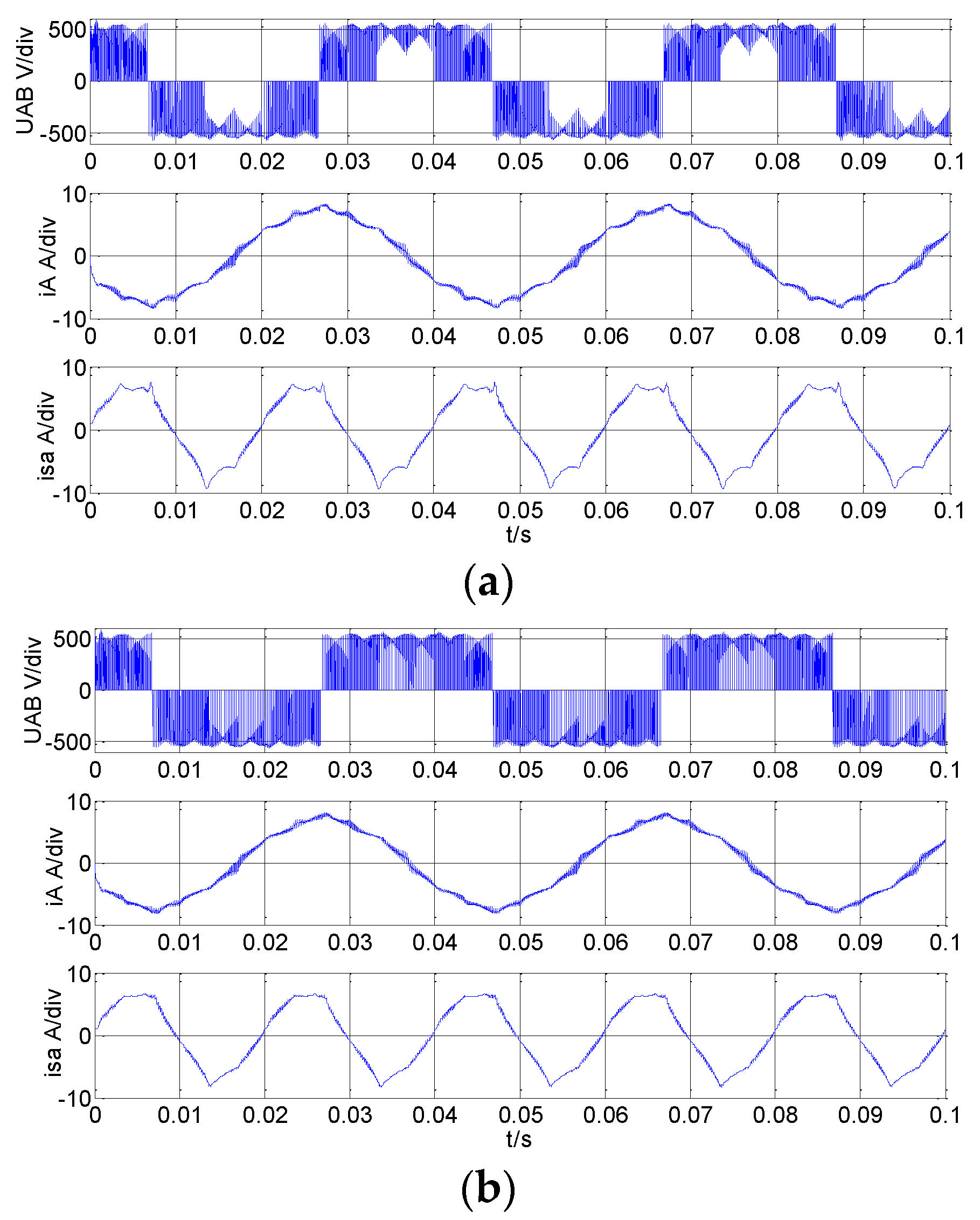
4.1. Simulation Research
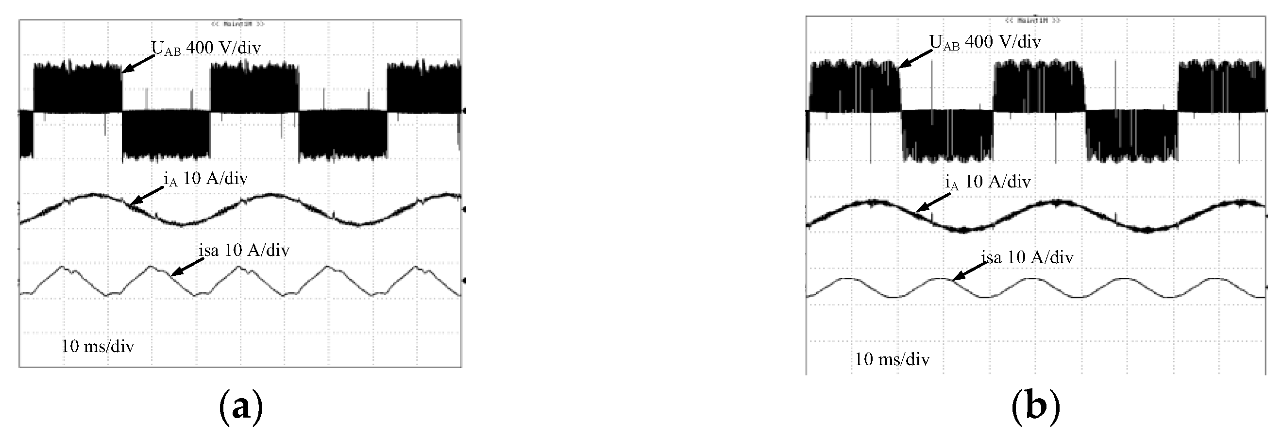
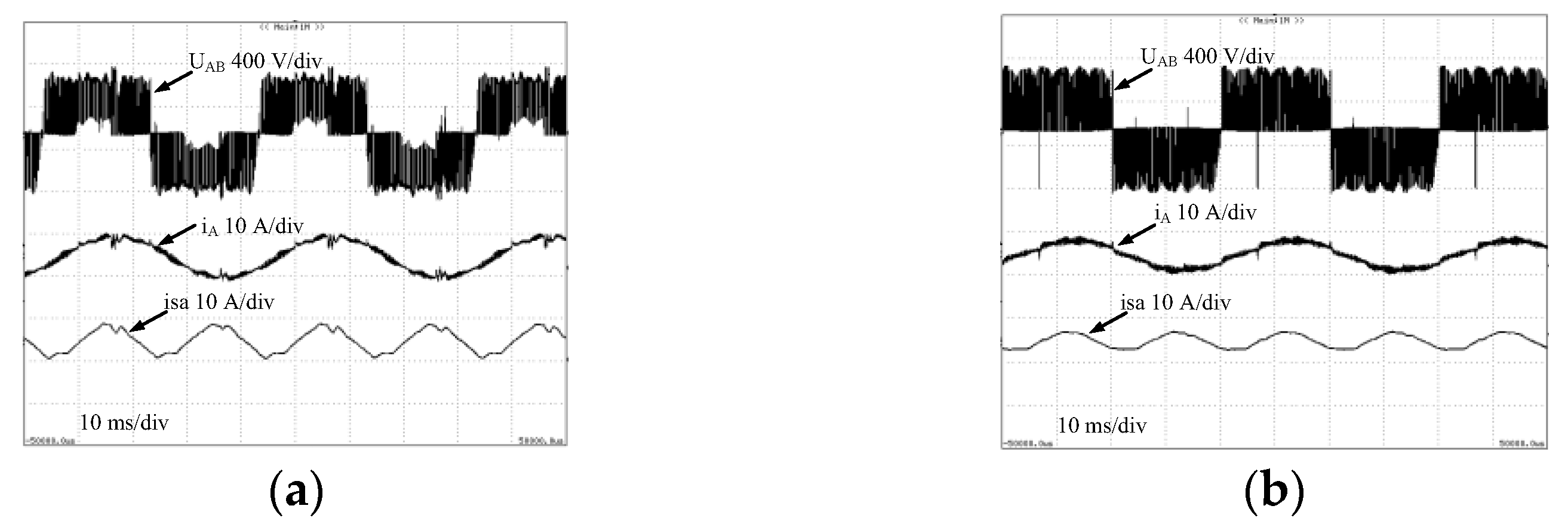
Direct MC simulated model is built by using Matlab software. The simulation parameters of the MC are set as Table 1. The over modulation strategy of the VSI uses the method in [17].
Figure 6 shows the relation between output voltage Uom and modulation index M. Figure 7a,b shows relations among output phase current and input phase current and modulation index M. It can be seen that the output voltage error is lower with the proposed input current vector optimal modulation than the no optimal modulation method from Figure 6. Meanwhile, it can be known that the output voltage amplitude is increased when the ratio of the hexagon vector to the input current vector increased. Compared to the no optimal modulation method, the input current THD is obviously decreased with the proposed input current vector optimal modulation strategy, especially M < 0.98, but the output current THD is almost the same with and without optimal modulation strategy. Simulation results are consistent with theoretical analysis, indicating that theoretical analysis is right and the proposed optimal modulation strategy is feasible.
Figure 8 and Figure 9 show waveforms of output line voltage and phase current and input phase current with and without optimal modulation strategy under M = 0.88 and M = 0.92, respectively. It can be seen that the quality of input current with the proposed optimal modulation strategy is obviously better than with no optimal modulation strategy, and the quality of output current with the proposed optimal modulation strategy is slightly better than with no optimal modulation strategy.

4.2. Experiments

To testify the validity of the proposed overmodulation method, the direct MC prototype with rated power 5 kW has been built in the laboratory. Experimental parameters are the same as the simulation parameters. The input and output current THD and output voltage error are listed in Table 2. isa, and iA, and Uerr are a-phase input current, and A-phase output current, and output Voltage error. It can be known that the input current THD and output voltage error with the optimized overmodulation strategy is lower and smaller than with the traditional overmodulation.
Figure 10 and Figure 11 show waveforms of output line voltage and phase current and input phase current with and without optimal modulation strategy under M=0.88 and M = 0.92, respectively. It can be seen that the quality of input current with the proposed optimal modulation strategy is obviously better than with no optimal modulation strategy; the quality of output current with the proposed optimal modulation strategy is slightly better than with no optimal modulation strategy; and the output voltage error is lower with the proposed optimal modulation strategy by analyzing the output current experimental waveforms. Experimental results are consistent with simulation results, verifying that theoretical analysis is right and the proposed optimal modulation strategy is feasible.

5. Conclusions

The MC is very suitable for AC adjustable speed control. However, low Voltage ratio of the MC restricts its application. The traditional overmodulation method based on optimizing both of the rectifier and inverter stages of the MC can significantly improve the VTR of the MC, but it can lead to big input current THD and output voltage error. To overcome the defects of the traditional overmodulation method, an optimal overmodulation strategy based on the rectifier stage of the MC is proposed, and the input current vector is synthesized by the hexagon vector and the inscribed vector. Simulation results indicate that the proposed overmodulation strategy of the rectifier stage of the MC by optimizing input current vector combinations and their weights can have smaller output voltage error and lower input current THD than the traditional overmodulation, experimental results verify that theoretical analysis is right and the proposed overmodulation strategy of the rectifier stage of the MC is feasible.

Author Contributions

Formal analysis, Y.X. and X.Z.; Investigation, L.H.; Project administration, Z.Y.; Validation, Z.W.; Writing—original draft, Y.X. All authors have read and agreed to the published version of the manuscript.

Funding

This work is supported by the National Natural Science Foundation of China under Grant 51507183, 51877212, 51807197.

Institutional Review Board Statement

This article does not involve ethical review.

Informed Consent Statement

Not applicable.

Data Availability Statement

Not applicable.

Acknowledgments

Thanks for the support of the National Natural Science Foundation of China.

Conflicts of Interest

The authors declare no conflict of interest.

References

  1. Li, X.; Su, M.; Sun, Y.; Dan, H.B.; Xiong, W. Modulation strategies based on mathematical construction for matrix converter extending the input reactive power range. IEEE Trans. Power Electron. 2014, 29, 654–664. [Google Scholar] [CrossRef]
  2. Alexandre, B.; Guilherme, P.; Pedro, C.; Lijun, Z.; Ferreira, P.S.; Fernando, S.J. On the potential contributions of matrix converters for the future grid operation, sustainable transportation and electrical drives innovation. Appl. Sci. 2021, 11, 4597. [Google Scholar]
  3. Varajão, D.; Araújo, R.E. Modulation methods for direct and indirect matrix converters: A review. Electronics 2021, 10, 812. [Google Scholar] [CrossRef]
  4. Mengoni, M.; Zarri, L.; Tani, A.; Rini, G.; Serra, G.; Casadei, D. A modulation strategy for matrix converter with extended control range and reduced switching power losses. In Proceedings of the IEEE Energy Conversion Congress and Exposition (ECCE), Denver, CO, USA, 15–19 September 2013; pp. 2721–2728. [Google Scholar]
  5. Pipolo, S.; Formentini, A.; Trentin, A.; Zanchetta, P.; Calvini, M.; Venturini, M. A new modulation approach for matrix converter. In Proceedings of the 10th International Conference on Power Electronics, Busan, Korea, 27–30 May 2019. [Google Scholar] [CrossRef]
  6. Huber, L.; Borojevic, D. Space vector modulated three-phase to three-phase matrix converter with input power factor correction. IEEE Trans. Ind. Appl. 1995, 31, 1234–1236. [Google Scholar] [CrossRef]
  7. Dabour, S.M.; Rashad, E.M. Analysis and implementation of space-vector-modulated three-phase matrix converter. IET Power Electron. 2012, 5, 1374–1378. [Google Scholar] [CrossRef]
  8. Pipolo, S.; Formentini, A.; Trentin, A.; Zanchetta, P.; Calvini, M.; Venturini, M. A novel matrix converter modulation with reduced number of commutations. IEEE Trans. Ind. Appl. 2021, 57, 4991–5000. [Google Scholar] [CrossRef]
  9. Rodriguez, J.; Kazmierkowski, M.P.; Espinoza, J.R.; Zanchetta, P.; Abu-Rub, H.; Young, H.A.; Rojas, C.A. State of the art of finite control set model predictive control in power electronics. IEEE Trans. Ind. Inform. 2012, 9, 1003–1016. [Google Scholar] [CrossRef]
  10. Vargas, R.; Ammann, U.; Rodriguez, J. Predictive approach to increase efficiency and reduce switching losses on matrix converters. IEEE Trans. Power Electron. 2009, 24, 894–902. [Google Scholar] [CrossRef]
  11. Xia, C.; Zhao, J.; Yan, Y.; Shi, T. A novel direct torque control of matrix converter-fed PMSM drives using duty cycle control for torque ripple reduction. IEEE Trans. Ind. Electron. 2014, 61, 2700–2713. [Google Scholar] [CrossRef]
  12. Lee, K.-B.; Blaabjerg, F. Sensorless DTC-SVM for induction motor driven by a matrix converter using a parameter estimation strategy. IEEE Trans. Ind. Electron. 2008, 55, 512–521. [Google Scholar] [CrossRef]
  13. Siami, M.; Khaburi, D.A.; Rodriguez, J. Simplified finite control set-model predictive control for matrix converter-fed PMSM drives. IEEE Trans. Power Electron. 2018, 33, 2438–2446. [Google Scholar] [CrossRef]
  14. Lin, Z.J.; Hua, Z.J.; Gui, G.Y.; Luo, W.B.; Liu, W.H. Voltage transfer characteristic and harmonic analysis of matrix converter under over modulation. Proc. CSEE 2007, 27, 110–113. [Google Scholar]
  15. Su, M.; Li, D.-Y.; Sun, Y.; Yu, Y. Analysis of the over-modulation strategy for two-stage matrix converter. Proc. CSEE 2008, 28, 47–53. [Google Scholar]
  16. Liu, S.; Ge, B.; Jiang, X.; Abu-Rub, H.; Peng, F. Comparative evaluation of three Z-source/quasi-Z-Source indirect matrix converters. IEEE Trans. Ind. Electron. 2015, 62, 692–701. [Google Scholar] [CrossRef]
  17. Kun, D.Q.; Juan, G.H.; Quan, L.G. Over-modulation strategy of matrix converter based on multi-orbit vector weighted. Trans. China Electro Tech. Soc. 2011, 26, 100–106. [Google Scholar]
  18. Li, S. Improving voltage transfer ratio of matrix converter employing single-mode and two-mode overmodulation technology. In Proceedings of the 2009 Second International Conference on Intelligent Computation Technology and Automation, Changsha, China, 10–11 October 2009; Volume 3, pp. 71–74. [Google Scholar]
  19. Tamai, Y.; Sato, I.; Odaka, A.; Mine, H.; Itoh, J.I. A novel control strategy for matrix converter in the over-modulation range. Electr. Eng. 2009, 168, 40–48. [Google Scholar] [CrossRef]
  20. Song, W.; Zhong, Y.; Wei, X.; Sun, X. Space vector over-modulation strategy used for two-stage matrix converters. Trans. China Electrotech. Soc. 2012, 27, 242–250. [Google Scholar]
  21. Bozorgi, A.M.; Monfared, M.; Mashhadi, H.R. Two simple over-modulation algorithms for space modulated three-phase to three-phase matrix converter. IET Power Electron. 2014, 7, 1915–1924. [Google Scholar] [CrossRef] [Green Version]
  22. Zhang, L.W.; Liu, Y.; Wen, X.H. A novel algorithm of SVPWM inverter in the over-modulation region based on fundamental voltage amplitude linear output control. Proc. CSEE 2005, 25, 12–18. [Google Scholar]
  23. Li, Y.; Qiu, L.; Zhi, Y.; Yan, G.; Zhang, J.; Ma, J.; Fang, Y. An over-modulation strategy for matrix converter under unbalanced input voltage. IEEE Access 2021, 9, 2345–2356. [Google Scholar] [CrossRef]
  24. Li, S.; Chen, W.; Yan, Y.; Shi, T.; Xia, C. A multimode space vector over-modulation strategy for ultrasparse matrix converter with improved fundamental voltage transfer ratio. IEEE Trans. Power Electron. 2018, 33, 6782–6793. [Google Scholar] [CrossRef]
  25. Rahman, K.; Al-Emadi, N.; Iqbal, A.; Rahman, S. Common mode voltage reduction technique in a three-to-three phase matrix converter. IET Electr. Power Appl. 2018, 12, 254–263. [Google Scholar] [CrossRef]
  26. Li, S.; Xia, C.; Yan, Y.; Shi, T. Space vector overmodulation strategy for ultra sparse matrix converter based on the maximum output voltage vector. IEEE Trans. Power Electron. 2017, 32, 5388–5397. [Google Scholar] [CrossRef]
  27. Bingsen, W.; Venkataramanan, G. Six step modulation of matrix converter with increased voltage transfer ratio. In Proceedings of the 37th IEEE Power Electronics Specialists Conference, Jeju, Korea, 18–22 June 2006; pp. 1–7. [Google Scholar]
  28. Guang, G.; Jian, Y.; Yao, S.; Su, M.; Zhu, Q.; Blaabjerg, F. A predictive-control-based over-modulation method for conventional matrix converters. IEEE Trans. Power Electron. 2018, 33, 3631–3643. [Google Scholar]
  29. Xia, Y.; Zhang, X.; Qiao, M.; Yu, F.; Wei, Y.; Zhu, P. Research on a new indirect space vector over-modulation method in matrix converter. IEEE Trans. Ind. Electron. 2016, 63, 1130–1141. [Google Scholar] [CrossRef]
Figure 1. The topology structure of MC.
Electronics 11 02009 g001
Figure 2. Fictitious AC-DC-AC structure of matrix converter.
Electronics 11 02009 g002
Figure 3. The input current sectors and synthetic principal.
Electronics 11 02009 g003
Figure 4. Six output voltage vectors and sectors.
Electronics 11 02009 g004
Figure 5. Curve of output voltage THD varies with p.
Electronics 11 02009 g005
Figure 6. The relation between output voltage Uom and index M.
Electronics 11 02009 g006
Figure 7. Relations among output phase current and input phase current and modulation index M: (a) the relation between output current THD and index M; (b) the relation between input current THD and index M.
Electronics 11 02009 g007
Figure 8. The waveforms of output line voltage and phase current and input phase current with and without optimal over modulation strategy under M 0.88: (a) with no optimal over modulation strategy; (b) with optimal over modulation strategy.
Electronics 11 02009 g008aElectronics 11 02009 g008b
Figure 9. The waveforms of output line voltage and phase current and input phase current with and without optimal overmodulation strategy under M 0.92: (a) with no optimal over modulation strategy; (b) with optimal over modulation strategy.
Electronics 11 02009 g009
Figure 10. The waveforms of output line voltage and phase current and input phase current with and without optimal over modulation strategy under M 0.88: (a) with no optimal over modulation strategy; (b) with optimal over modulation strategy.
Electronics 11 02009 g010
Figure 11. The waveforms of output line voltage and phase current and input phase current with and without optimal over modulation strategy under M 0.92: (a) with no optimal over modulation strategy; (b) with optimal over modulation strategy.
Electronics 11 02009 g011
Table 1. Matrix converter parameters.
NameParameters
Input phase voltage220 V/50 Hz
Input filterRf = 50 Ω, Lf = 2 mH, Cf = 11.25 µF
Switch frequencyfs = 5 kHz
RL loadR = 40 Ω, L = 8 mH
Table 2. The input and output current THD and output voltage error.
The Overmodulation StrategiesParameters
THD (isa)THD (iA)Uerr (UA)
with no optimal input current synthesized (M = 0.88)10.14%7.14%13.6 V
with optimal input current
synthesized (M = 0.88)
5.1%6.14%4.28 V
with no optimal input current synthesized (M = 0.92)13.4%10.35%12.37 V
with optimal input current
synthesized (M = 0.92)
10.06%10.14%5.26 V
Publisher’s Note: MDPI stays neutral with regard to jurisdictional claims in published maps and institutional affiliations.

