1. Introduction
The conversion of various forms of energy into electricity has been known for decades. Lately, hydrogen energy has often been mentioned, which is converted into electricity through a component known as a Fuel Cell (FC), and has thermal energy and technical water as a by-product. Therefore, this type of conversion is environmentally friendly concerning the use of oil and petroleum products for this purpose. Compared to gasoline engines, Proton Exchange Membrane Fuel Cells (PEMFCs) have fewer efficiency losses, zero emissions, and no thermal losses of moving parts. It is believed that a fuel cell can solve the problem of energy and car transport. FCs are one of the most promising sources of renewable energy. It is a “green energy” source because it has no nitrogen oxide and sulfur emissions and can work with exceptionally low noise levels. Fuel cell systems have the advantage of being modular and can, therefore, be built in a wide range of power requirements, from a few hundred watts up to kilowatts or megawatts. In addition, they can provide energy in a controlled way with higher efficiency than conventional power plants. In a fuel cell, the chemical energy is provided by a fuel and an oxidant stored outside the cell, in which the chemical reactions take place. If the cell is supplied with fuel and an oxidant, electrical power can be obtained. The use of fuel cells has its share of both advantages and disadvantages, compared to conventional energy converters. The main disadvantage is still the associated excessive cost.
A fuel cell, unlike a battery, generates electricity instead of storing it and continues to do so if the fuel supply is maintained. Compared to battery-powered Electric Vehicles (EVs), a fuel-powered vehicle has the advantage of a longer driving range without a long battery charging time. Compared to Internal Combustion Engine (ICE) vehicles, FCs powered vehicles have the advantages of high energy efficiency and much lower emissions, due to the direct conversion of energy from fuel to electricity without combustion.
Fuel Cell Electric Vehicles (FCEVs) are powered by hydrogen. FCEVs and the hydrogen fuel infrastructure are in the initial stages of implementation, and refueling is still a major challenge for fuel cell vehicles. The storage of hydrogen in the vehicle is a major concern. In order to refuel cells, a hydrogen tank must be attached to the vehicle. FCEVs use a propulsion system similar to electric vehicles, where energy stored as hydrogen is converted into electricity using a fuel cell. Like conventional internal combustion engine vehicles, FCEVs can refuel in less than 4 min, and have a range of over 300 miles. FCEV vehicles are equipped with advanced technologies to increase efficiency, such as a regenerative braking system that captures energy lost during braking, storing it in the battery. Large car manufacturers offer a limited but growing number of FCEV production vehicles to the public in certain markets, in line with what developing infrastructure can support.
The conversion of fossil fuel-powered vehicles into environmentally friendly battery-powered vehicles has been extensively discussed in the literature [
1,
2,
3]. The basic principle is to remove the existing fossil fuel engine and any associated equipment not needed for the conversion. There are two cases of conversion; the first is where the existing gearbox is retained during the conversion, and the second, which is more complex, is where the existing gearbox is removed together with the engine. Each of these two conversion cases has its pros and cons. In the case of the conversion, which, in our case, was conducted within the Faculty of Transport and Traffic Engineering in Doboj, Bosnia and Herzegovina according to the project request, a small vehicle, intended for the transport of up to two people and with a small range and low maximum speed, up to 50 km/h [
4], was selected. A small serial 2 kW DC motor was chosen for this, due to its robustness and large starting torque. The old gearbox was also retained, and the conversion was much easier. Absorbent Glass Mat (AGM) batteries are used, which have limited possibilities for use in electric vehicles. The redesigned vehicle was characterized by rather modest features (low maximum speed, short range, and a long battery charging time of 6–8 h). All this represented certain restrictions in the use of the modified vehicle.
To maintain the demand for an environmentally friendly vehicle, it was necessary to choose a new technology that provides the ability to solve some of the mentioned shortcomings, including the vehicle range and charging speed. As a logical choice, the solution that uses fuel cells was adopted, primarily because it represents an environmentally friendly technology and solves some additional problems that are otherwise related to electric vehicles (e.g., the problem of heating the vehicle cabin in winter) [
5,
6]. A system using PEM-type fuel cells was chosen as an additional energy source due to its cost and simple implementation [
6]. The operating temperature of these cells is in the range of 80 °C–90 °C, which is quite enough to solve the problem of heating the passenger cabin in the winter.
As part of the research, a model of a PEM fuel cell system developed in the MATLAB/Simulink software package was proposed. A model of the vehicle, including the battery power and the fuel cells, was also made.
Simulation of a model was for driving conditions with constant acceleration. The model tested for two energy sources, battery-powered and hydrogen-powered; the results are obtained and presented below.
The paper is structured as follows:
Section 1 contains an introduction to the issue.
Section 2 deals with thematic considerations in related work.
Section 3 describes the Hybrid Electric Vehicles (HEV) with dual energy sources as well as the model of the HEVs with AGM/PEMFC power supplies.
Section 4 gives some discussion, which is followed by conclusions and possible further investigations in
Section 5.
2. Related Work
Diverse types of PEMFC models have been discussed in the literature. Due to the lack of product information on the precise values of the parameters needed for PEMFC modeling, parameter extraction is an important task. Thus, to obtain the actual effect of a PEMFC, its parameters must be identified by an optimization technique. Related work points to important parameters and modeling methods, although specific parameter values are often not listed. It is important to perform the extraction of essential parameters for successful optimization. Nevertheless, most of the literature lists the parameters and deals with the model synthesis and testing. Yet, an analysis of suitable literature sources will establish a list of important parameters in various PEMFC models.
In [
7], the modeling and regulation of an HEV are explored to optimize system performance for fuel efficiency by combining an electric motor, a battery, and an internal combustion engine. An ANFIS controller was used to analyze the engine and motor performance. Special attention was paid to decreasing the internal combustion engine’s fuel consumption. A novel PHEV system that supports the power sources, the transmission, and the control system is presented. The proposed Sugeno-type ANFIS controller based on fuzzy rules was trained. Performances were analyzed by simulating driving in a city and on a highway, while three drive cycles (sets of data points that show the speed of a vehicle as a function of time) were chosen. The results show that ANFIS had better fuel economy when utilizing different control strategies.
A comprehensive review paper [
8] provides insight into the performance of various technologies. Opportunities for fuel economy improvement are especially highlighted when further engine downsizing is limited. In addition, strategies for achieving emission reductions have been identified. The possibilities of the Atkinson cycle, as well as TEGs and thermodynamic bottoming-cycle engines, have been studied. Choice of parameters is especially important for the creating a model.
The work presented in [
9] deals with high-temperature proton exchange membrane fuel cells. This technology enables faster electrode kinetics, high CO tolerance, and possible waste heat recovery. A comparison of the parallel, serpentine, and hybrid flow configurations using a physics-based fuel cell model is given. The results indicate that “the hybrid configuration with the net power output of 0.383 W/cm
2 provides the best performance with an auxiliary power loss of 3.6% compared to the serpentine configuration with an 11% loss”. How to achieve a reduction in auxiliary power losses has also been shown.
Older works have been used to gain a general insight into the problems of HEV modeling, and the evidence of the problems and shortcomings of individual approaches is clear.
According to [
10], the advantages of FCEVs are vehicle mobility and that they do not produce any emissions. The paper defines the main problems in an electric vehicle as autonomy and charging time. The use of hydrogen fuel cells in electric vehicles increases autonomy and reduces the charging time of electric vehicles. According to [
10], the fuel cell has the function of charging the battery of an electric vehicle extended range (REEV) or acts directly as a power supply for a component of the FCEV electric motor.
The research presented in [
11] deals with a model of an HEV drive assembly with both battery-powered and FC-powered. The system simulation is based on empirical formulations and MATLAB/Simulink blocks. The accelerator pedal signal is generated by the driving schedule as the primary input; the simulation implements the power flow difference and control under the following vehicle operating modes: start, cruise, acceleration, and pause. The research shows that the FC system in HEVs can restore the battery State of Charge (SOC) while meeting the requirements of vehicle speed and driving power.
The research presented in [
12] introduced a one-dimensional mathematical model for studying a PEMFC system’s operation and efficiency. The model considered processes occurring in the system. The model results were compared with some different methods and models, such as a quasi-2D model of a fuel cell, and demonstrated the different characteristics of the proposed models. In [
13], the authors consider the basic principles of fuel cells and provide the opportunity to gain an insight into the significant developments that have emerged over the past five years. In [
14], the authors presented the fundamentals, theory, and design of conventional cars with ICEs, EVs, HEVs, and FCVs. The systematic design of fuel cell hybrid drive trains is introduced, and the concept of fuel cell hybrid vehicles is established. The operating principles and control of the drive train are analyzed. These three literature sources are suitable for gaining general insights into the issue.
Furthermore, in [
15], a general methodology for designing a hybrid fuel cell vehicle propulsion system is given, followed by the methodology and a description of a computer simulation program. This research deals with the main function of the control strategy to ensure the proper control of the power produced by the fuel cell system and the peak energy source, and to maintain the energy level of the peak energy source in its optimal area. This type of control of the fuel cell system enables work in the field of high efficiency. In [
16], the authors gave an overview of the technology of hybrid electric vehicles, but the paper also lists the factors required in the process of developing hybrid electric vehicles. The classification of hybrid electric vehicles based on the layout of internal combustion engines and electric traction motors is given. The types of batteries required and the use of power electronic converters for efficient processing and the use of energy in a hybrid electric vehicle are described. The study described in [
17] presented a model of a commercial PEMFC (5 kW). The application of this model enabled the assembly of complex systems and applications.
The authors of [
18] cite several benefits of using FCHVs in the transport sector, including reducing greenhouse gas emissions by replacing fossil fuels with hydrogen as energy carriers. The authors examine different management strategies to optimize the power distribution between the battery and the PEM fuel cell to maximize the efficiency of the system and reduce fuel consumption. The results [
18] show that the FC system in the HEV can increase the state of charge (SOC) of the battery while meeting the requirements of high speeds and vehicle power. The results of the research show that, in low load cycles and high load cycles, the best control strategies achieve a fuel cell system efficiency equal to or greater than 33%, while fuel consumption is 30% lower than the basic control strategy in low-load driving cycles.
The authors of [
19] present hybrid and battery electric vehicles, so-called “green cars”. Due to the one-way nature of the transformation of energy into FCV, an auxiliary energy storage system is necessary because it copes with the peak demand for power and the return of braking energy. The authors propose an algorithm for sizing the FC and the auxiliary storage system, taking into account the strategy of energy division between the two energy sources.
According to [
20], the efficiency of an EV depends on the proper functionality and management of energy storage in the battery. Battery energy stored in an EV provides an unregulated, unstable power supply and has significant voltage drops. Power electronics converter technology in EVs is necessary to achieve a stable state and for reliable energy transfer.
The authors of [
21] argue that the Energy Management Strategy (EMS) in Hybrid Electric Fuel Vehicles (FCHEV) is key to improving the optimal energy distribution. This paper describes a new health-conscious EMS algorithm based on Model Predictive Control (MPC) which aims to minimize battery degradation in order to extend its life. The authors claim that the proposed EMS has been experimentally confirmed on a PEMFC delivery vehicle.
The authors of [
22] deal with the problem of energy management to ensure the best charging performance in electric vehicles. The topic of the paper is finding the poor condition of the control of a hybrid charging system by regrouping photovoltaic cells and fuel cells. A mathematical model of the charging system considers a power management loop, the vehicle load, and a gradual mathematical modeling of each component. The results presented suggest that, despite the additional weight of the PV panels, the combination of PV and FC systems improves the energy performance of the vehicle and provides a higher charging capacity compared to FC alone. Comparison with similar studies shows that the proposed model is more efficient.
The results of previous research suggest the possibility of modeling HEVs by considering research conducted on a particular car, as well as some theoretical aspects. The MATLAB/Simulink environment was found to be suitable for the model development. The contribution of the paper, in addition to the specific model developed, is an insight into the modeling process in cases where there are numerous limitations in terms of available equipment, tools, and other resources.
3. Design of a Hybrid Electric Vehicle with Dual Energy Sources
The aim of this research is to increase the security of the vehicle’s energy supply and vehicle range, rather than to perform the classic conversion of a battery-powered electric vehicle system into a hydrogen-powered vehicle to retain both energy sources. The goal of the research is a model of concrete hybrid electric vehicle with dual energy sources, namely, a battery source and a hydrogen source. The battery-powered energy source is provided by the AGM battery pack, and the hydrogen-powered is provided by the FC system. In the event of an AGM battery failure, the FC system takes over the role of supplying the vehicle with energy, and vice versa. The result of the research is a model designed with two AGM/PEMFC power supplies.
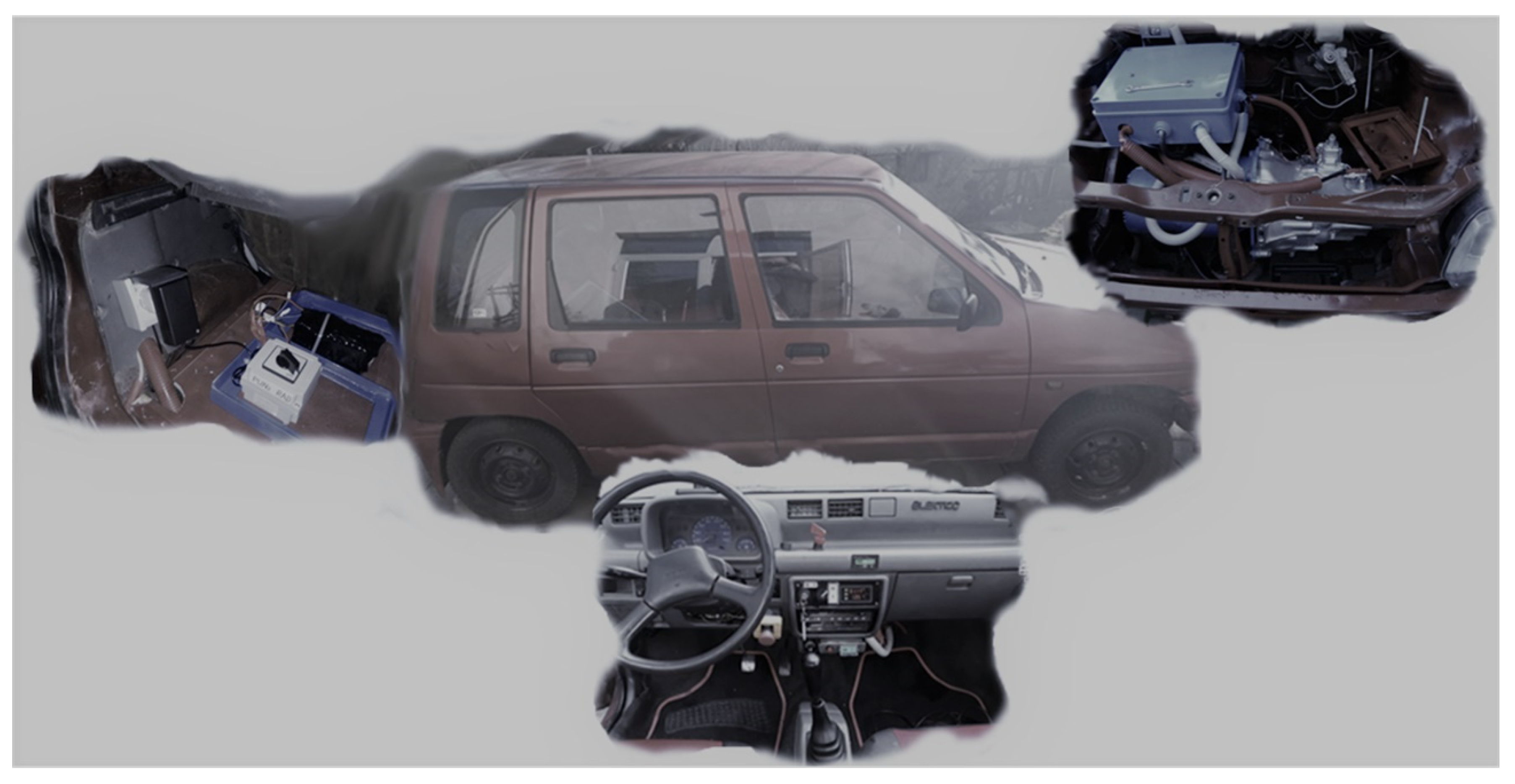
The Daewoo Tico electric vehicle was made in the laboratory of the Faculty of Transport and Traffic Engineering in Doboj, Bosnia and Herzegovina, in 2019. The Daewoo Tico is a prototype vehicle for experimental research with the possibility of registration and uses in urban areas,
Figure 1.
The Daewoo Tico is a lightweight vehicle (approximately 640 kg, maximum permissible mass: 1025 kg). The vehicle has a propulsion motor manufactured in the factory (“Rade Končar”, Zagreb, Croatia) with the following characteristics: power—2 kW, supply voltage—40 V, current—72 A, speed—1650 rpm. The battery-powered energy source is an AGM (absorbent glass mat) battery pack.
The Daewoo Tico electric vehicle has the following characteristics:
- (a)
Maximum vehicle velocity up to 50 km/h;
- (b)
Range of 15–20 km with one charge.
The vehicle is intended for the transport of goods and passengers, i.e., for the transport of the driver plus one passenger (150 kg), which would make the total mass of the vehicle with the planned passengers 790 kg.
The vehicle speeds in different gears—for a maximum engine speed of 1980 rpm with a connected voltage of 48 V—are:
First gear: 12 km/h;
Second gear: 20.8 km/h;
Third gear: 32.29 km/h;
Fourth gear: 47.37 km/h;
Fifth gear: 54.8 km/h.
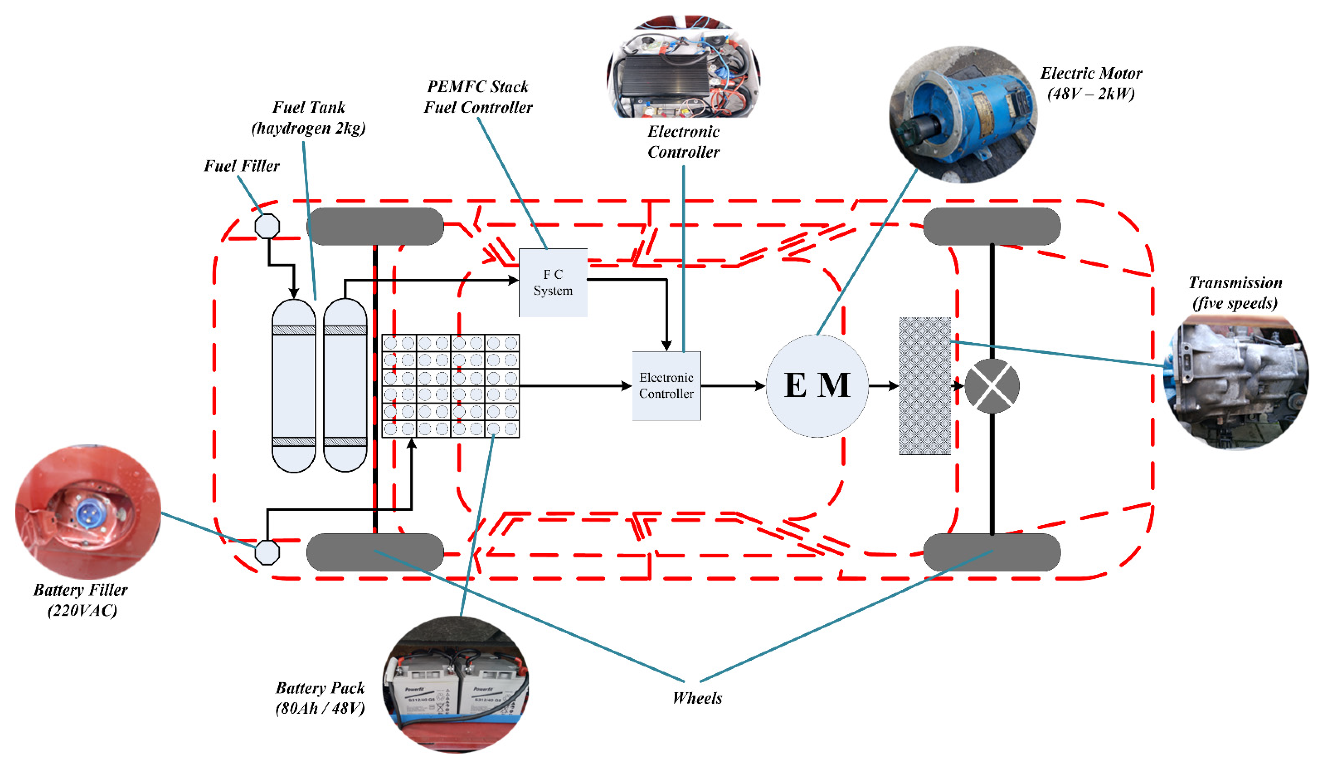
The paper proposes the improvement of the Daewoo Tico electric vehicle with a hydrogen-powered energy source. Accordingly, the Daewoo Tico EV is converted into an HEV with two energy sources. The hydrogen-powered energy source is provided by the FC system, the fuel tank (2 kg), and the fuel filter. The FC system consists of a PEMFC stack and a fuel controller that controls the operation of this system. The PEMFC control system is connected to a battery controller which regulates the operation and charging of the AGM battery pack [
23]. The PEMFC stack is composed of PEMFCs that are connected in series and in parallel to obtain higher output voltages and currents compared to individual cells, whose operating output voltage is approximately 0.6 V. The operation of each PEMFC is important for the operation of the complete system for the purpose of the optimal and efficient use of hydrogen as a propellant. PEMFCs with optimal characteristics and low failure rates are of great importance for HEVs. The AGM battery pack has a capacity of 3.84 kWh, while the PEMFC pack consists of 80 individual fuel cells with a total voltage of 48 V.
Figure 2 shows the proposed design of the HEV with two energy sources.
The calculation of the HEV motor power, for a maximum velocity of 50 km/h, can be calculated approximately using the following formula:
In Equation (1), m = 790 kg—vehicle mass (with two passengers), v = 14 m/s = 50.4 km/h—velocity in m/s, f = 0.0081—rolling resistance coefficient, cd = 0.38—aerodynamic drag coefficient, A = 1.95 m2—surface height * vehicle width.
Based on the motor power, the series DC motor was selected as the vehicle’s drive motor. The proposed design of the HEV has at least two power sources, a fuel cell (FC) system as a power source [
24,
25], and an AGM (absorbent glass mat) battery package [
14]. The drive batteries are 48 V with a capacity of 80 Ah (3.84 kWh). The PEMFC package consists of 80 PEMFCs connected in series. The hydrogen and battery powered supplies provide power of HEV [
5,
6,
12].
4. Model of HEV with AGM/PEMFC Energy Sources
MATLAB/Simulink was used to design the HEV model with dual AGM/PEMFC energy sources. In the case of observation, the HEV can use only one of the two built-in energy sources. The complementarity of energy sources in HEV is left for further research.
The theoretical value of the PEMFC output voltage can be calculated using the expression for Gibbs free energy (Equation (2)).
In Equation (2), E is the electromotive force at the ends of the PEMFC, is the Gibbs free energy per mole, and F is the Faraday’s constant F = 96,485 C.
Equation (3) expresses the partial pressure of the hydrogen, oxygen, and water effect on the value of the electromotive force.
In Equation (3), E is the electromotive force at the ends of the fuel cell, E0 is the emf at standard pressure, PH2 is the hydrogen pressure at the entrance of the fuel cell, PO2 is the pressure of oxygen, PH2O is atmospheric pressure, P0 is the standard atmospheric pressure usually assumed to be 1 bar, R = 8.314 JK−1mol−1 universal gas constant, T is PEMFC temperature, while F is the Faraday’s constant.
The practical value of the open circuit voltage
Eoc is:
In Equation (4), E is the electromotive force defined by Equation (3), and i0 is the current density at which the output voltage begins to fall.
The output electrodes generate the potential difference, and if the consumer is connected, an electric current will flow. Based on Equation (5) for electromotive force, a PEMFC model is proposed:
In Equation (5), EOC is the real practical value of the open circuit voltage, B = 0.05 V, f is the specific resistance of the surface of the fuel cell, in is the internal current density related to the internal power loss, and iL is the limiting current density.
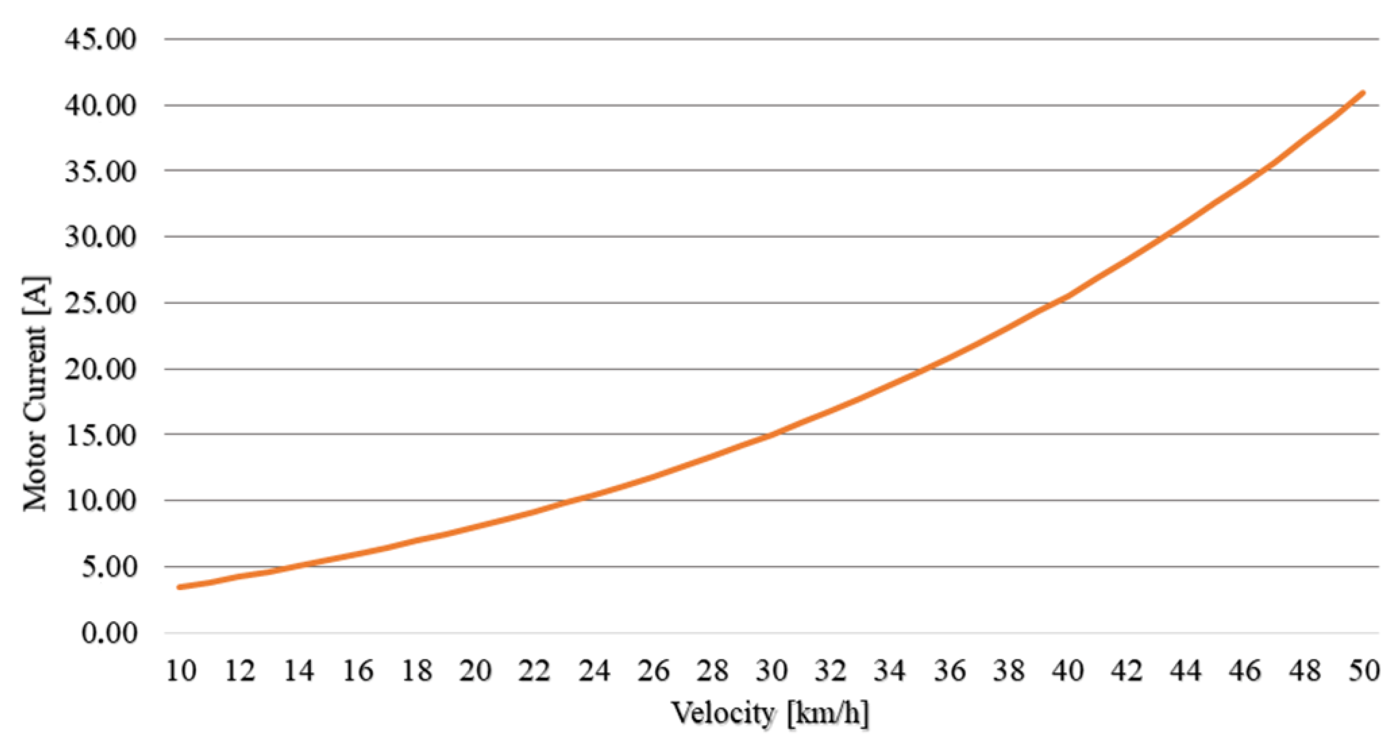
Based on the input set parameters, the maximum speed of the vehicle is 50 km/h, while the required motor power is 2018 W and the value of the current on the motor is 40.91 A. To find the consumption of H
2 fuel cells, it is convenient to use a sample that considers the current that the engine takes from the energy source (Equation (6)).
In Equation (6), ξH2 is the hydrogen consumption rate (mol/s), Imotor is the motor current flow (A), NFC is the number of fuel cells, and F = 96,485 Cmol−1 Faraday’s constant.
The calculation of the hydrogen consumption
mH2 is as follows:
In Equation (7), ξH2 is the hydrogen consumption rate (mol/s), M is the molecular mass, and M = 2 gmol−1.
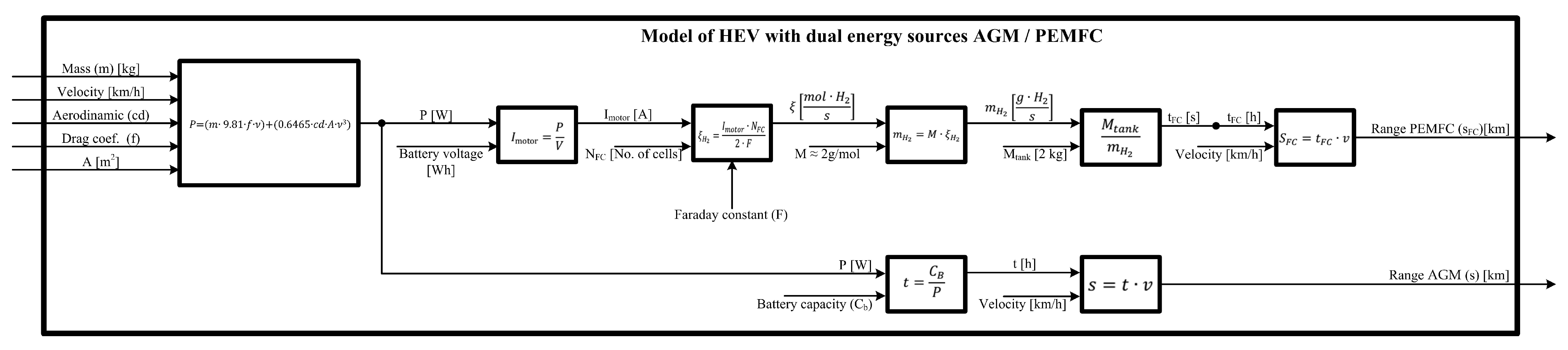
A model of two energy sources has been proposed, consisting of AGM/PEMFC energy sources.
Figure 3 shows the layout of the model for an HEV with two energy sources (AGM/PEMFC).
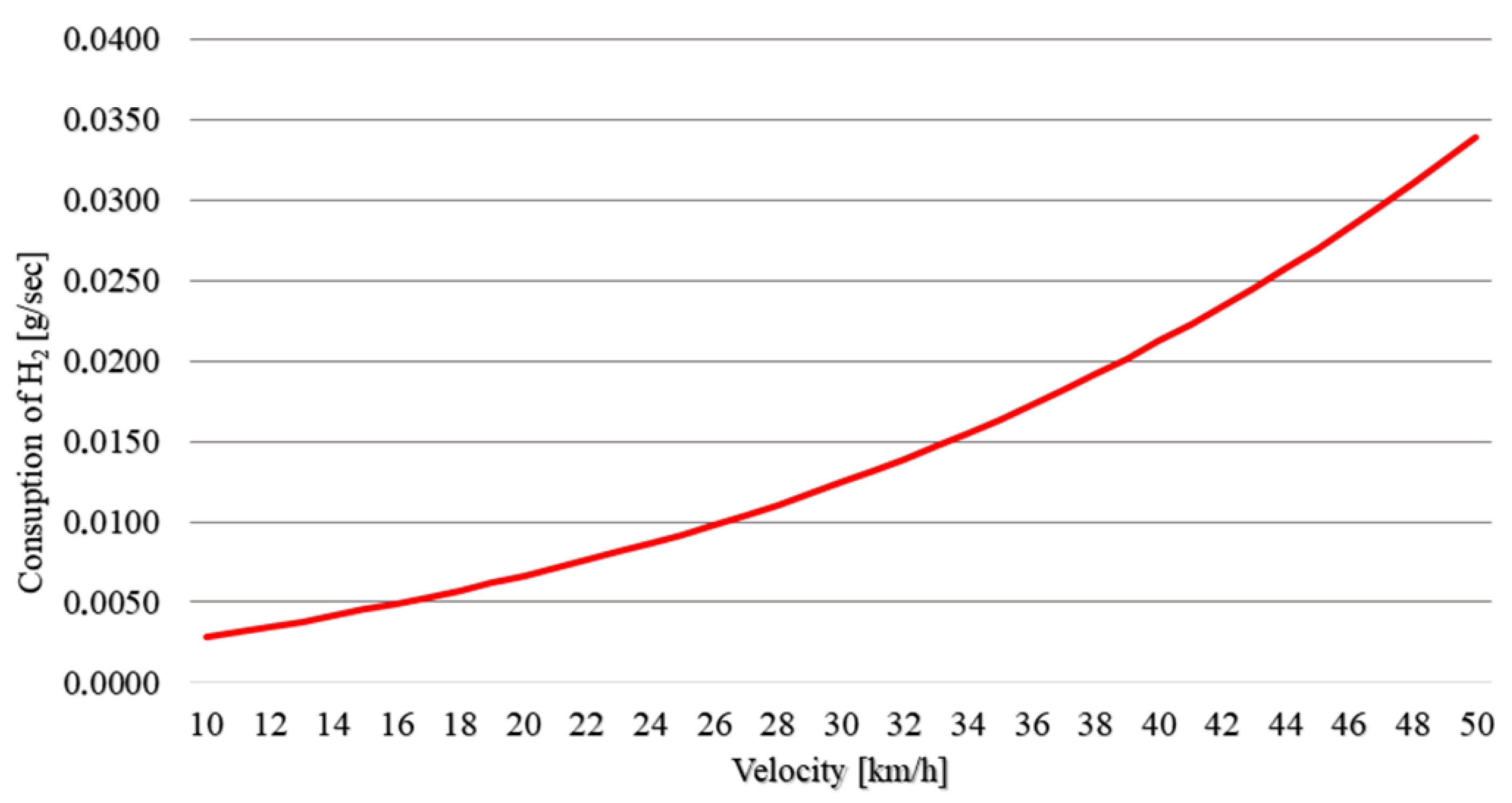
The capacity of the hydrogen tank of 2000 g was determined regarding the maximum vehicle velocity of 50 km/h and the hydrogen consumption of mH2 = 0.033 gs−1.
A model of the HEV with two AGM-power and PEMFC-power energy sources was created. The aim was to design the HEV with stable operation at different velocities, to increase the vehicle range, and to reduce the AGM charging time. This primarily depends on the operation of the AGM battery pack and the FC system. An analysis of the model of the HEV with two energy sources was performed concerning both AGM-powered and PEMFC-powered vehicle ranges.
5. Results and Discussion
The main goal of this paper relates to increasing the range of the Daewoo Tico electric vehicle at different velocities under restrictions relating to keeping the vehicle’s mass as low as possible, shortening the vehicle’s battery charging time, and making the power source environmentally friendly. Increasing the range of the Daewoo Tico electric vehicle could be achieved in the following ways:
- ■
By increasing the capacity of the existing AGM stack of the Daewoo Tico electric vehicle, which at the same time will drastically increase the vehicle range and AGM charging time, and thus, would negatively affect the driving characteristics of the vehicle;
- ■
By installing a fuel cell module that would be powered by a hydrogen tank (2 kg) and that would not greatly increase the mass of the Daewoo Tico electric vehicle; however, the charging time of the hydrogen tank would be reduced compared to the battery charging time.
The paper presents the architecture of an HEV with a built-in module based on a PEMFC, so that the vehicle has two energy sources: AGM and PEMFC (
Figure 2). A model was designed in the MATLAB/Simulink software package that simulated the range of the vehicle at different velocities for both the AGM and PEMFC energy sources separately.
Data analysis was performed based on the data shown in
Table 1. Data were generated from a model of the two energy sources: AGM and PEMFC.
The analysis of the model was performed for different vehicle velocities, ranging from 10 km/h to 50 km/h (see
Table 1).
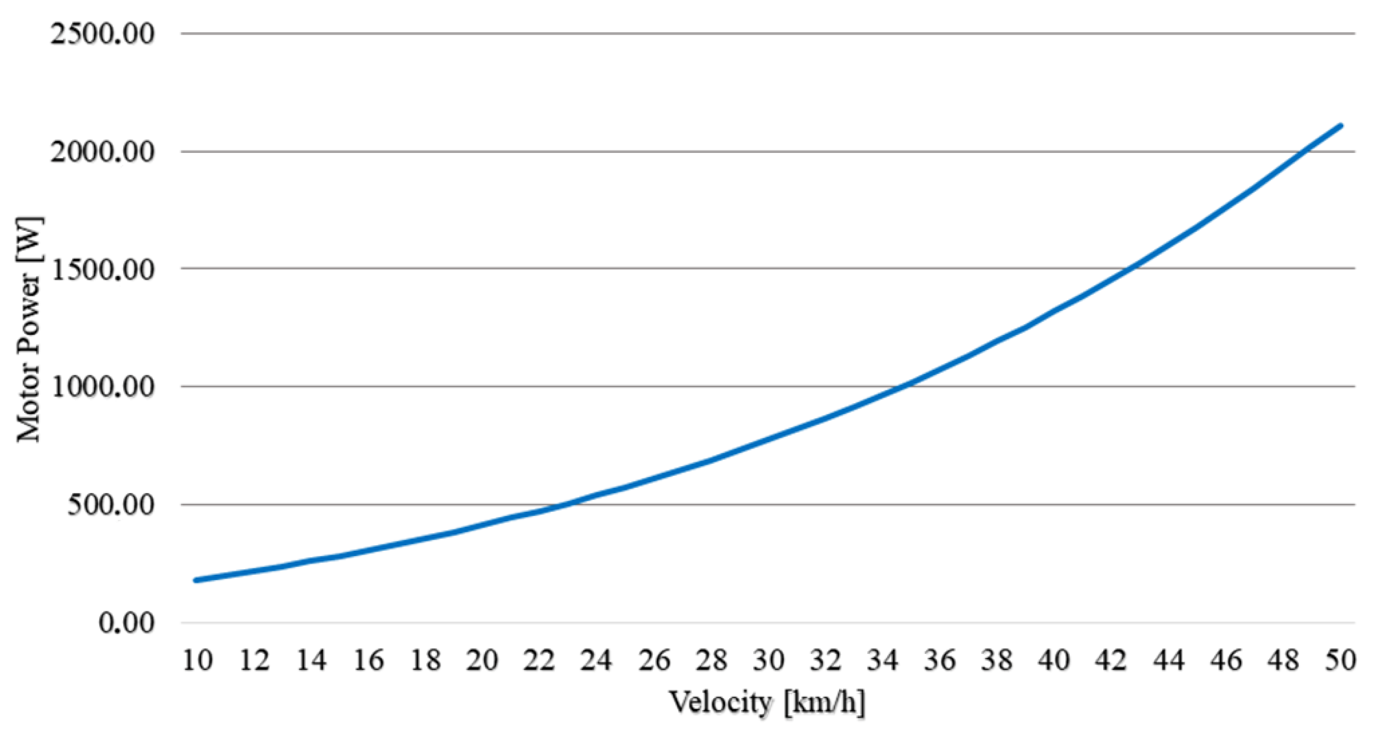
Figure 4 shows the dependence of the DC motor power required for the vehicle to achieve a given velocity. For lower velocities, this dependence is an approximately linear function, while with increasing velocities, the DC Motor Power becomes the dominant element of velocity and the power required to reach the given velocity has faster growth. It is important to note that, for a higher velocity, in addition to friction, the aerodynamic drag coefficient
cd from Equation (1) lays a significant role.
Figure 5 shows the dependence of the motor current on the velocity. The analysis assumes that the voltage on the AGM is constant, and that there is no voltage drop due to the increase in the motor current. The obtained simulation results were confirmed by experimental measurements on a modified ElekTico [
4] vehicle.
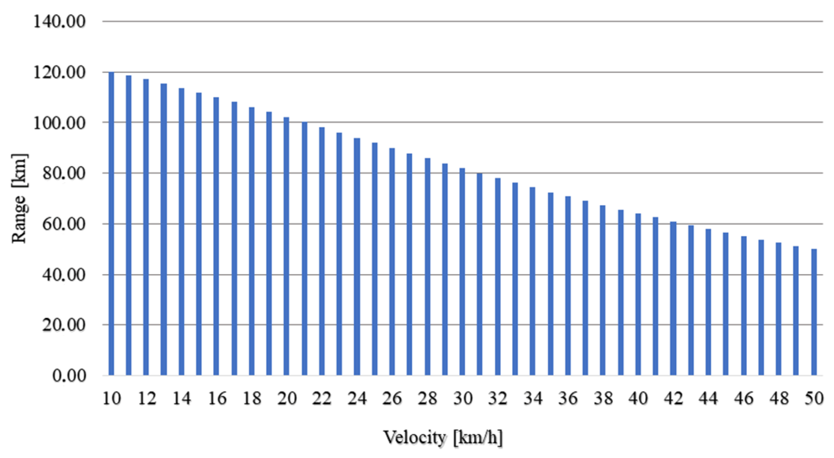
One of the key features of an HEV is the range with a 100% charged AGM power supply. It is known that electric vehicles require more power from the AGM stack at higher velocities. The AGM stack capacity directly depends on the value of the AGM discharge current and decreases with increasing velocity. Based on the proposed model in the MATLAB/Simulink package, the characteristic of the dependence of the vehicle range on the velocity is simulated: the range will drop drastically with increasing velocity; see
Figure 6.
Additionally, the basic characteristics of an HEV based on two energy sources (AGM/PEMFC) were analyzed. The MATLAB/Simulink model for the HEV version of the vehicle was developed, and the characteristic consumption of hydrogen (H
2), depending on the velocity of the vehicle, was given. In
Figure 7, the dependence of the consumption of H
2 in g/sec is visible.
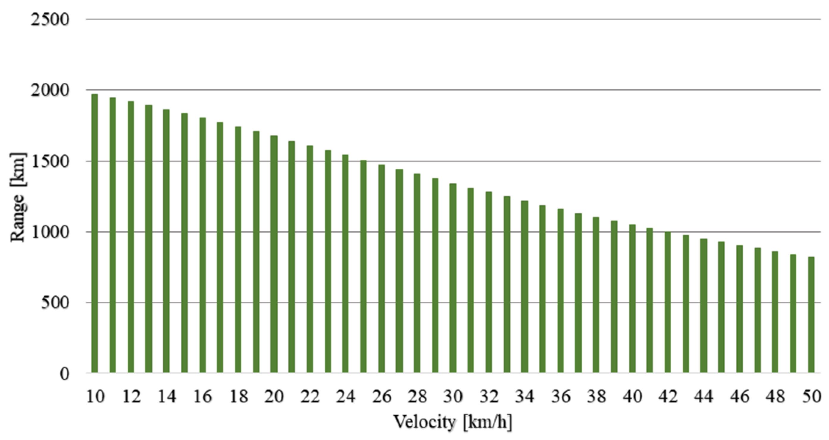
The range of the newly proposed FC-based vehicle, depending on the velocity of movement, is shown in
Figure 8.
One of the important features of a hybrid vehicle is the range of the EV (
Figure 6) and the HEV (
Figure 8).
Figure 6 and
Figure 8 show that the HEV range of the PEMFC-powered vehicle with a tank capacity of 2 kg is significantly higher than the AGM-powered vehicle. The AGM stack with 48 V, 80 Ah, and a mass of about 120 kg is much heavier than the PEMFC stack tank capacity of 2 kg. The characteristics in
Figure 5 and
Figure 7 show that the amount of electricity and hydrogen that the motor draws from the source depends on the velocity of the HEV, and this amount increases drastically with increasing velocity over 25 km/h. The characteristics from
Figure 6 and
Figure 8 are approximately the same in appearance, and the equality between the required current and the required amount of hydrogen could be drawn.
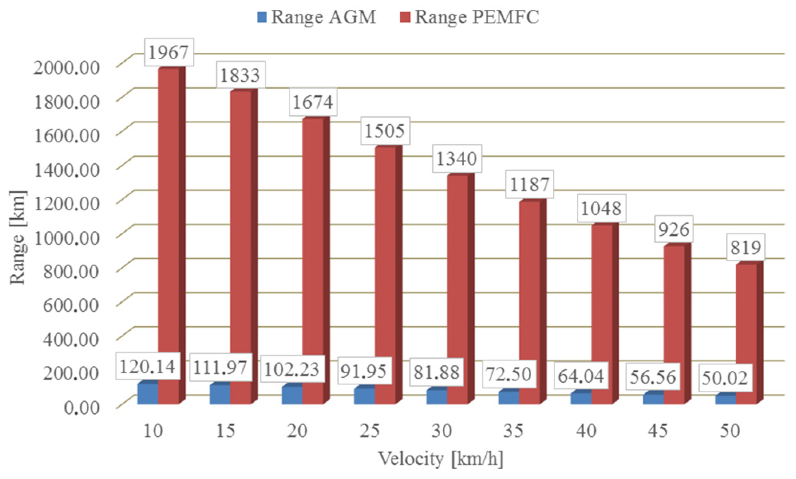
Figure 9 shows the relationship between the two energy sources in the HEV, in case only one of the two energy sources is active. Analyzing the graph shown in
Figure 9, we can see that the HEV range is much higher when a PEMFC power source is used. The ratio between the range of the AGM source and the range of the PEMFC source is ≈16:1, which means that, more precisely, 16.372 AGM stacks replace one PEMFC stack. The range of an HEV with one PEMFC stack is approximately equal to the range of 16 AGM stacks. In order for the HEV ranges to be the same with both PEMFC and AGM power sources, 16 AGM stacks should be installed in the vehicle. One AGM stack with a capacity of 48 V and 80 Ah has a mass of 120 kg, which implies that the mass of 16 AGM stacks is 1920 kg. In any case, a mass of approximately 2 tons is too much of a load for a 2 kW HEV engine.
The range—PEMFC value for the HEV reaches a maximum of 1967 km at 10 km/h, while the optimal velocity of an HEV in urban areas ranges from 30 km/h to 40 km/h. In urban areas, the optimal PEMFC range is between 1340 km and 1048 km, and optimal HEV range is between 1422.33 km and 1112.39 km. Finally, the contribution in kilometers (Contribution) and the benefits in range (Benefit) for different HEV velocities in this research are shown in
Table 2.
The lowest Contribution (214.98 km) and Benefit (68.5%) will be for a velocity ranging from 40 km/h to 50 km/h. The contribution of 275.09 km and the benefit of 87.7% will refer to the speed in the range between 10 km/h and 20 km/h, and 274.16 km and the benefit of 87.4% between 30 km/h and 40 km/h. The highest Contribution (313.16 km) and Benefit (100%) will be achieved at a velocity ranging between 20 km/h and 30 km/h. Based on the analysis, we can conclude that the recommendation for achieving the maximum benefit in range when converting an AGM-powered vehicle to an AGM/PEMFC-powered HEV would be for a velocity ranging between 20 km/h and 30 km/h.
6. Conclusions
The paper deals with the conversion of an existing Daewoo Tico electric vehicle (EV) into a hybrid electric vehicle (HEV). Of particular importance is the increase in vehicle range in urban areas, where the optimal vehicle velocity is from 30 km/h to 40 km/h. The proposed HEV design, in addition to increasing the range of the vehicle, implies limitations in terms of the reduced mass of the power sources as well as the total mass of the HEV, the reduced refueling time, and the low conversion costs.
The paper discusses two ways to increase the range of EV Daewoo Tico with the previously mentioned limitations.
The first way considered in the paper is to increase the capacity of existing batteries for the Daewoo Tico EV. Such a solution would cause a drastic increase in the vehicle mass and AGM charging time, and reduce the battery life as a power source, which would negatively affect the vehicle’s driving characteristics. Moreover, batteries, as a technological waste, can have a bad effect on the environment.
Another way considered in the paper is the installation of an FC module that would be powered by a hydrogen tank (2 kg). This solution would not significantly increase the mass of the Daewoo Tico electric vehicle, and the filling time of the H2 tank would be reduced compared to the charging time of the AGM. The lifespan of a fuel cell stack is environmentally friendly and is longer than the lifespan of an AGM stack.
In addition to the method of improving the range of an EV by installing several battery AGM stacks in it, the solution of introducing an additional power source in the form of an FC module was accepted.
The existing electric vehicle uses an AGM (absorbent glass mat) battery that gives it an autonomy of 15–20 km at a velocity up to 50 km/h, while the new design, in addition to the AGM, will use a proton exchange membrane fuel cell (PEMFC) beam containing 80 individual FCs with a total voltage of 48 V.
Model testing implies that only one of the energy sources is active at the observed time, avoiding the use of a management strategy. It is assumed that both power sources are 100% full at the time of the HEV’s startup. The results of the research show that the largest increase in the range of vehicles at a velocity between 20 km/h and 30 km/h is partly consistent with their use in urban areas. However, the increase in vehicle range at a velocity suitable for urban areas is 87.4%, compared to the previous EV, which may indicate a justification for the introduction of the PEMFC stack. However, although there is a tendency towards a cheap solution, the disadvantages of this approach are still the high cost of the PEMFC modules and the small number of hydrogen filling stations in Europe.


 ,
, 


