
Dimming Control Scheme of Visible Light Communication Based on Joint Multilevel Time-Shifted Coding


Abstract
:1. Introduction
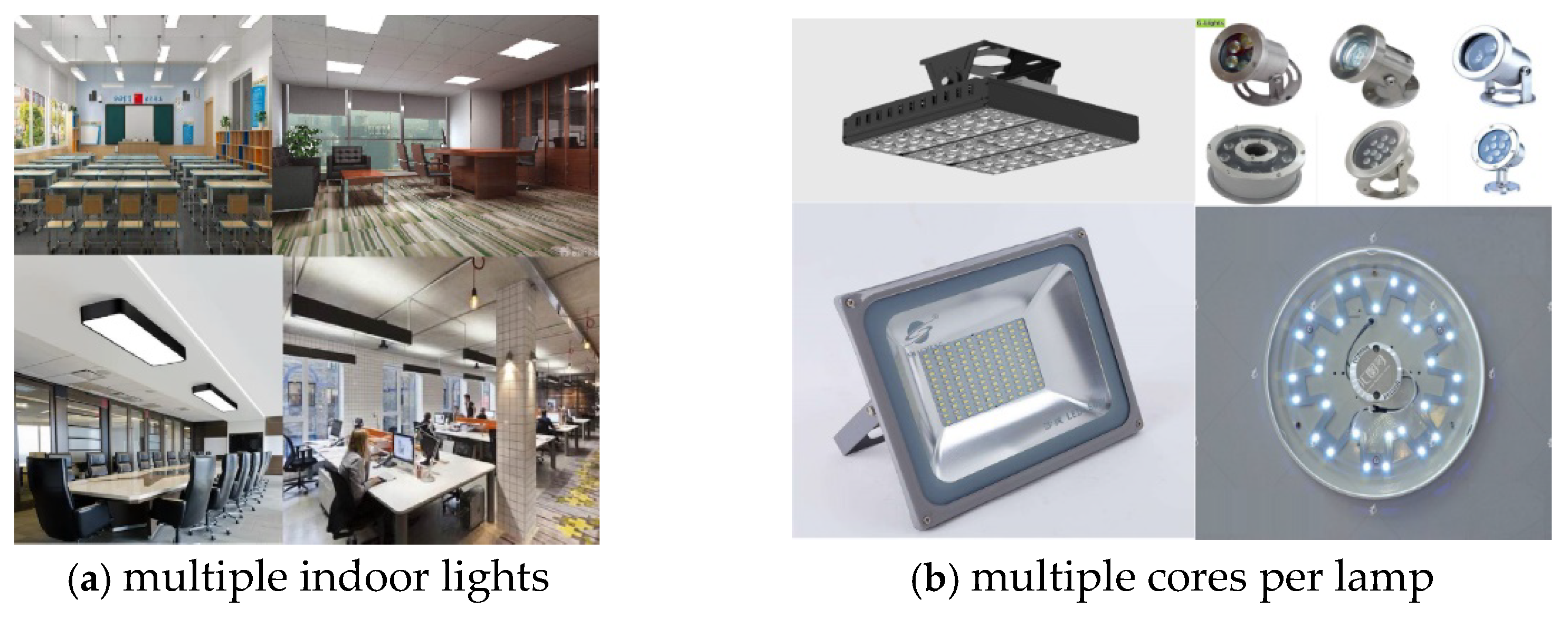
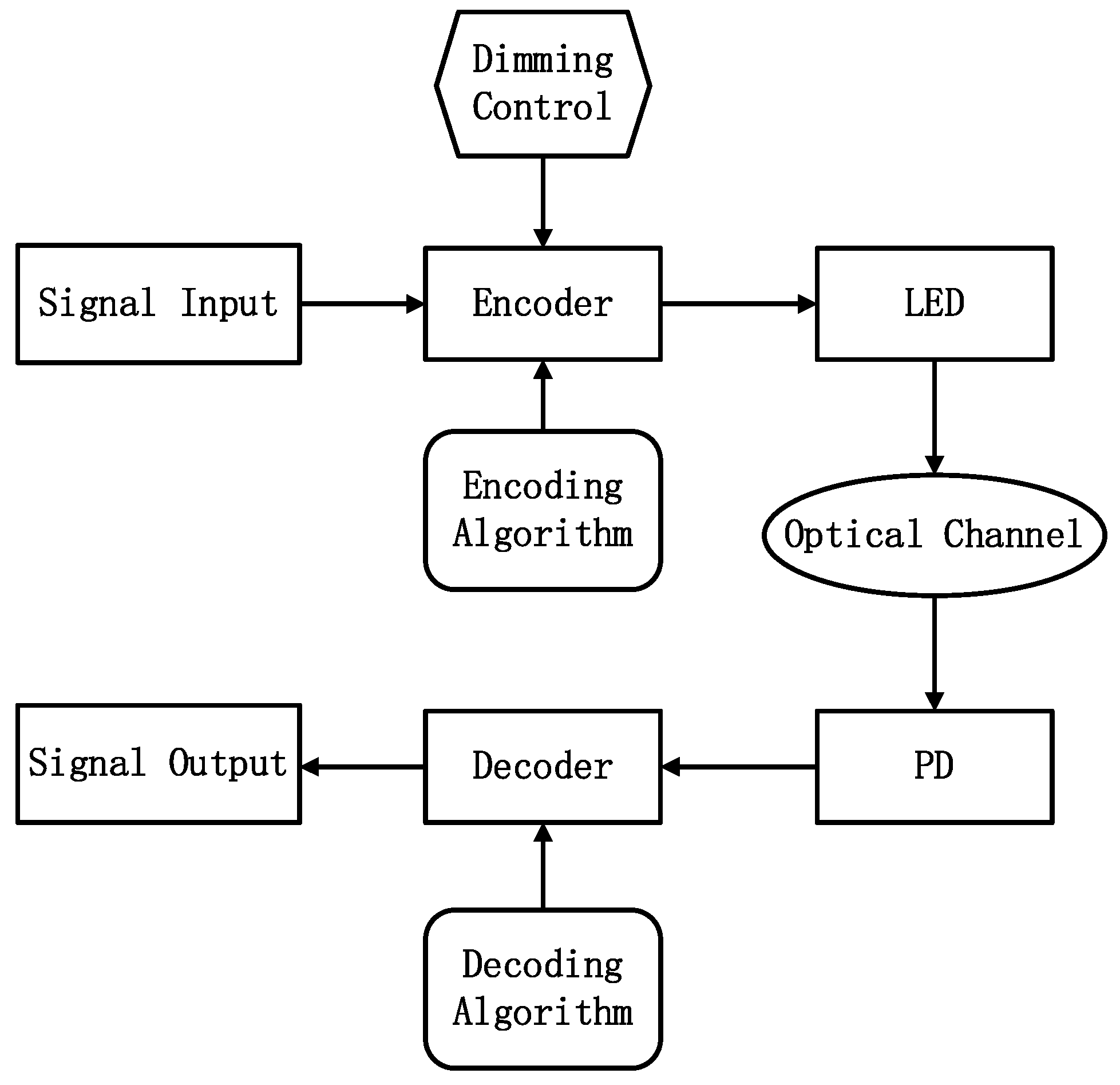
2. System Model
3. Dimming Control Scheme Based on ML-MTSC
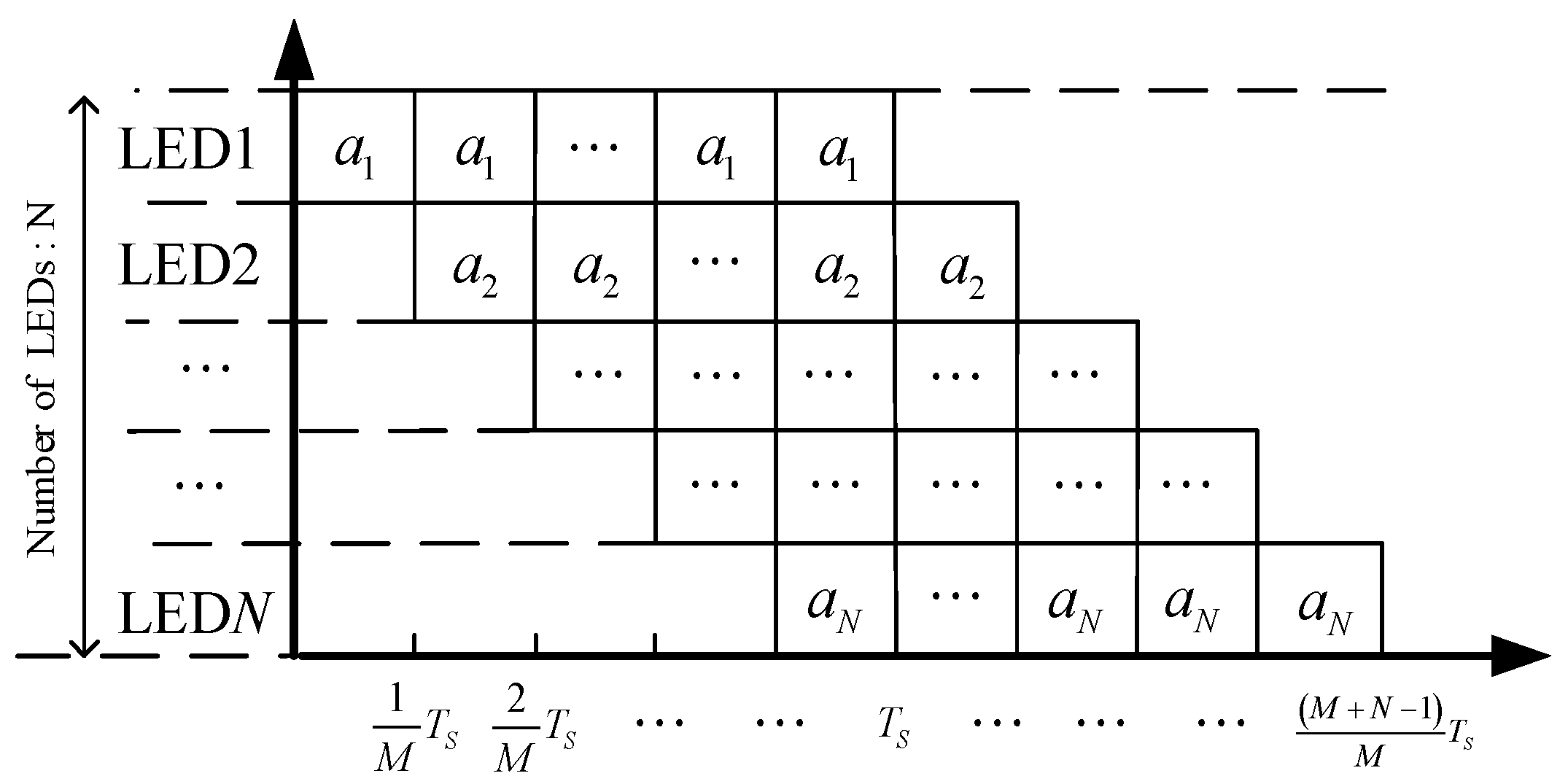
3.1. Codeword Structure
3.2. Implementation of the Algorithm
| Algorithm 1: Encoding Algorithm of the ML-MTSC Scheme |
| Input Dimming level , Number of LEDs , Number of cores per LED , Binary data of each LED needs to send. |
| Step 1. Divide the transmitted information of each LED into several length binary sequence |
| Step 2. The binary sequence of the th LED is mapped to the decimal symbol |
| Step 3. The number of slots is calculated according to Equation (7) |
| Step 4. Encode according to the codeword structure in Figure 3. |
| If |
| For |
| For |
| If |
| Else or |
| Else |
| For |
| For |
| If |
| Else or |
| Output Transmitted data matrix |
| End |
| Algorithm 2: Decoding Algorithm of the ML-MTSC Scheme |
| Input Number of LEDs , Dimming level , Number of cores in a LED , Received signal |
| Step 1. The number of slots is calculated according to Equation (7) |
| Step 2. Utilize ML detection algorithm to detect |
| The estimated transmitted signal sequence can be uniquely determined by looking up the table according to |
| Step 3. Map the decimal estimated value transmitted by the th LED in the previous step to a binary sequence with length . |
| Output The estimated value of the binary data that each LED needs to send |
| End |
4. Performance Analysis and Simulation Results
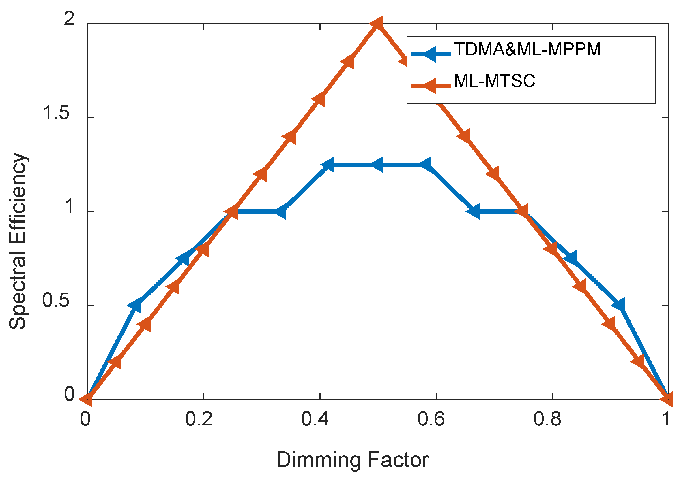
4.1. Spectral Efficiency
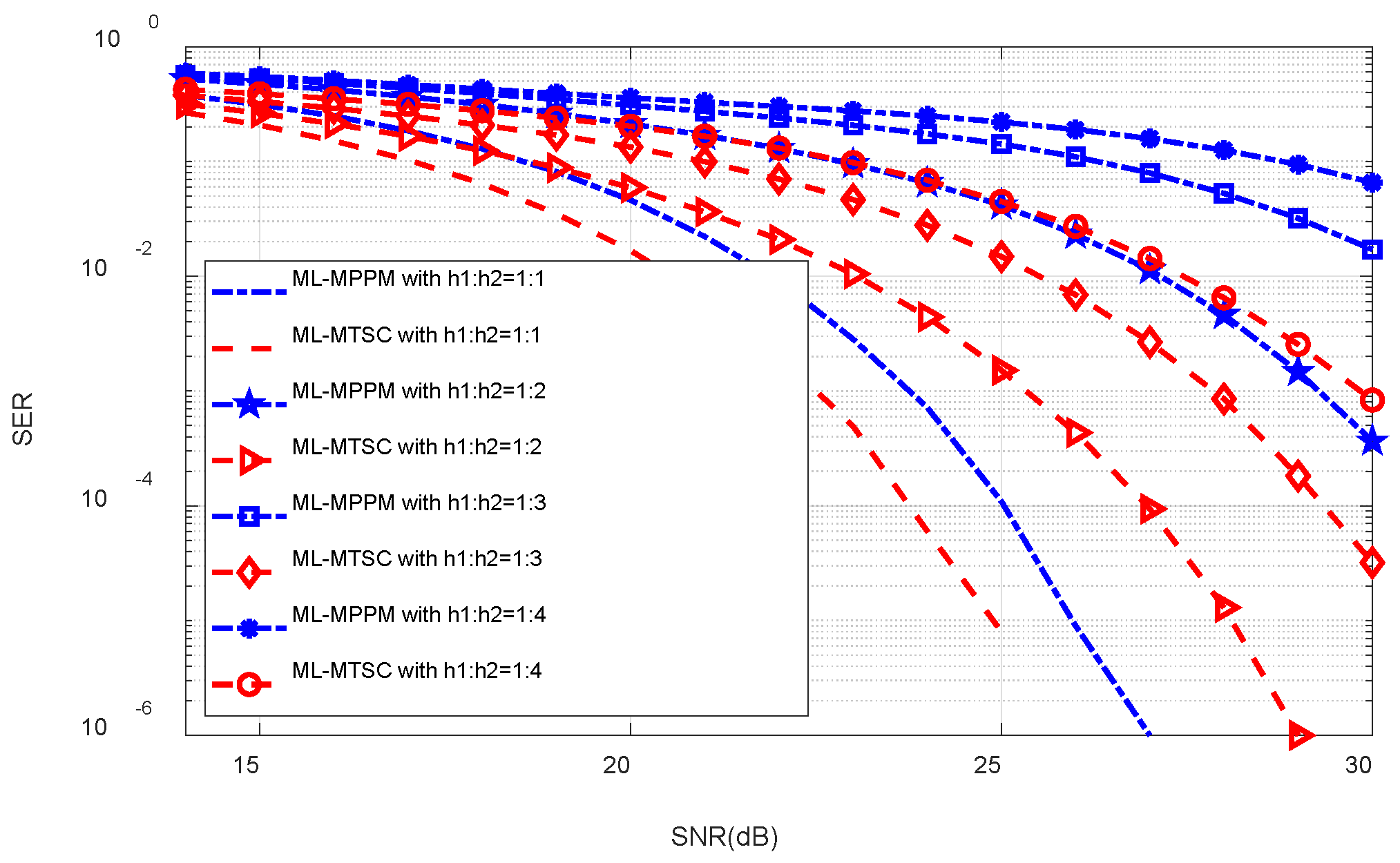
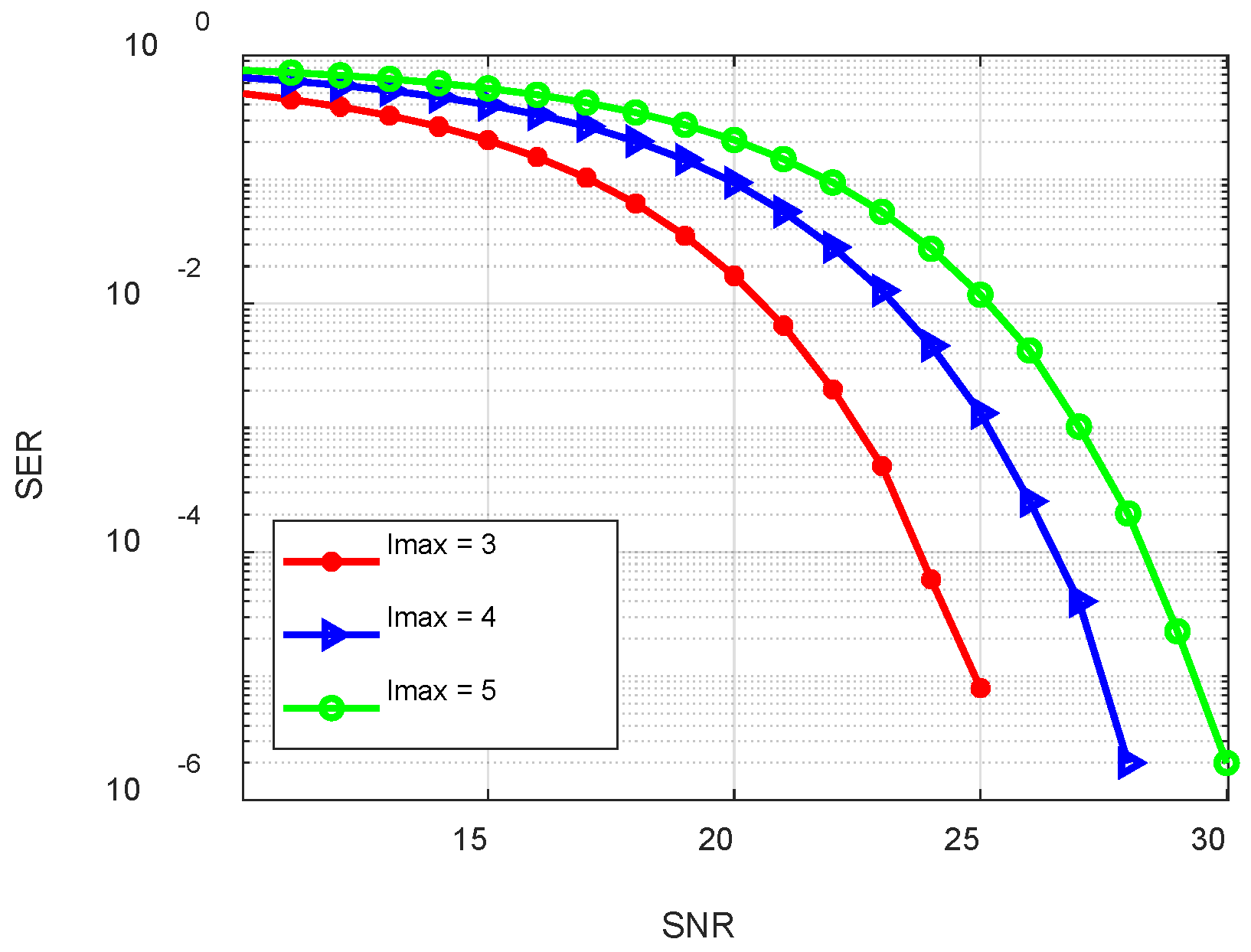
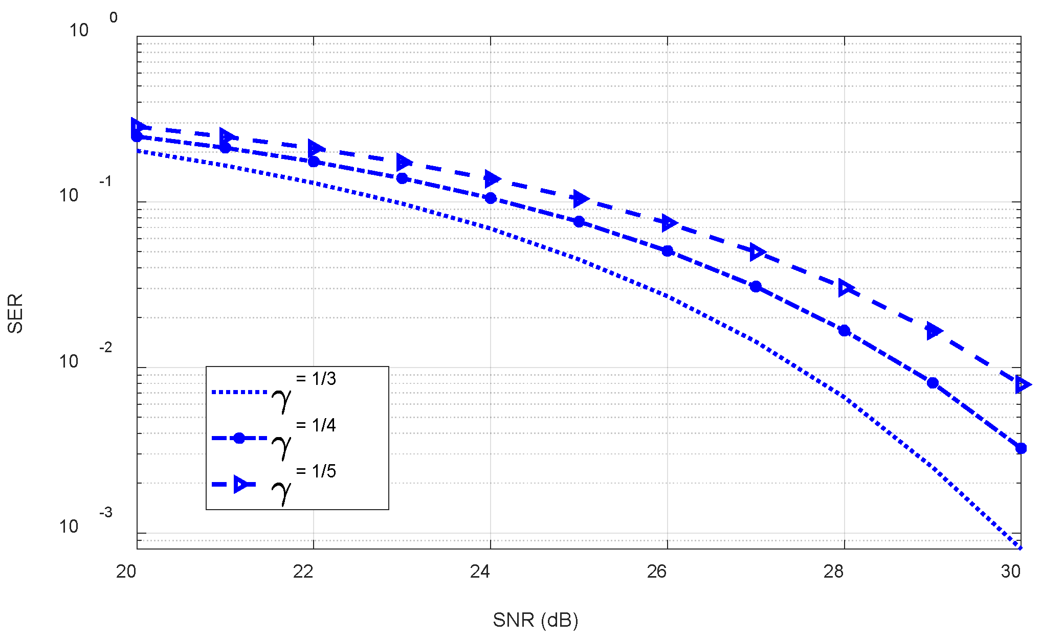
4.2. Bit Error Performance
5. Conclusions
Author Contributions
Funding
Informed Consent Statement
Conflicts of Interest
References
- Arfaoui, M.A.; Soltani, M.D.; Tavakkolnia, I.; Ghrayeb, A.; Safari, M.; Assi, C.M.; Haas, H. Physical layer security for visible light communication systems: A survey. IEEE Commun. Surv. Tutor. 2020, 22, 1887–1908. [Google Scholar] [CrossRef] [Green Version]
- Strinati, E.C.; Barbarossa, S.; Gonzalez-Jimenez, J.L.; Ktenas, D.; Cassiau, N.; Maret, L.; Dehos, C. 6G: The next frontier: From holographic messaging to artificial intelligence using subterahertz and visible light communication. IEEE Veh. Technol. Mag. 2019, 14, 42–50. [Google Scholar] [CrossRef]
- Wang, C.; Yang, Y.; Guo, C.; Zeng, Z.; Feng, C. Generalized dimming control scheme with optimal dimming control pattern for VLC. In Proceedings of the 2020 IEEE Wireless Communications and Networking Conference (WCNC), Virtual Conference, 25–28 May 2020; pp. 1–6. [Google Scholar]
- Li, B.; Xue, X.; Feng, S.; Xu, W. Layered Optical OFDM with Adaptive Bias for Dimming Compatible Visible Light Communications. J. Lightwave Technol. 2021, 39, 3434–3444. [Google Scholar] [CrossRef]
- Zhu, X.; Wang, F.; Shi, M.; Chi, N.; Liu, J.; Jiang, F. 10.72Gb/s Visible Light Communication System Based on Single Packaged RGBYC LED Utilizing QAM-DMT Modulation with Hardware Pre-Equalization. In Proceedings of the Optical Fiber Communications Conference and Exposition (OFC), San Diego, CA, USA, 11–15 March 2018; pp. 1–3. [Google Scholar]
- Islim, M.S.; Ferreira, R.X.; He, X.; Xie, E.; Videv, S.; Viola, S.; Watson, S.; Bamiedakis, N.; Penty, R.V.; White, I.H.; et al. Towards 10 Gb/s orthogonal frequency division multiplexing-based visible light communication using a GaN violet micro-LED. Photonics Res. 2017, 5, A35–A43. [Google Scholar] [CrossRef]
- Bian, R.; Tavakkolnia, I.; Haas, H. 10.2 Gb/s Visible Light Communication with Off-the-Shelf LEDs. In Proceedings of the 2018 European Conference on Optical Communication (ECOC), Rome, Italy, 23–27 September 2018; pp. 1–3. [Google Scholar]
- Bian, R.; Tavakkolnia, I.; Haas, H. 15.73 Gb/s Visible Light Communication with Off-the-Shelf LEDs. J. Lightwave Technol. 2019, 37, 2418–2424. [Google Scholar] [CrossRef] [Green Version]
- Zhu, Y.J.; Wang, W.Y.; Zhang, J.K.; Zhang, Y.Y. Constellation Collaborated Nonlinear Orthogonal Space–Time Block Codes with Fast Maximum-Likelihood Detection. IEEE Trans. Veh. Technol. 2017, 66, 513–528. [Google Scholar]
- Hussein, H.S.; Hagag, M. Optical MIMO-OFDM with fully generalized index-spatial LED modulation. IEEE Commun. Lett. 2019, 23, 1556–1559. [Google Scholar] [CrossRef]
- Feng, Z.; Guo, C.; Yang, Y. A novel hybrid dimming scheme for MU-MIMO-OFDM VLC system. In Proceedings of the ICC—IEEE International Conference on Communications (ICC), Shanghai, China, 20–24 May 2019; pp. 1–6. [Google Scholar]
- Wang, T.Q.; Green, R.J.; Armstrong, J. MIMO Optical Wireless Communications Using ACO-OFDM and a Prism-Array Receiver. IEEE J. Sel. Areas Commun. 2015, 33, 1959–1971. [Google Scholar] [CrossRef]
- Nuwanpriya, A.; Ho, S.W.; Chen, C.S. Indoor MIMO Visible Light Communications: Novel Angle Diversity Receivers for Mobile Users. IEEE J. Sel. Areas Commun. 2015, 33, 1780–1792. [Google Scholar] [CrossRef]
- Rajagopal, S.; Roberts, R.D.; Lim, S.K. IEEE 802.15.7 visible light communication: Modulation schemes and dimming support. IEEE Commun. Mag. 2012, 50, 72–82. [Google Scholar] [CrossRef]
- IEEE P802.15.7/D3; IEEE Draft Standard for Local and Metropolitan Area Networks—Part 15.7: Short-Range Optical Wireless Communications. IEEE Standard Association: Piscataway, NZ, USA, 2018; pp. 1–412.
- Zhang, D.F.; Yu, H.Y.; Zhu, Y.J. A multi-user joint constellation design of color-shift keying for VLC downlink broadcast channels. Opt. Commun. 2020, 473, 126001. [Google Scholar] [CrossRef]
- Guo, J.; Zhang, J.; Zhang, Y.; Xin, G. Efficient multi-LED dimming control scheme with space–time codes for VLC systems. Appl. Opt. 2020, 59, 8553. [Google Scholar] [CrossRef] [PubMed]
- Siddique, A. Bandwidth efficient multi-level MPPM encoding decoding algorithms for joint brightness-rate control in VLC systems. In Proceedings of the 2014 IEEE Global Communications Conference, Austin, TX, USA, 8–12 December 2014. [Google Scholar]
- Guo, J.N.; Zhang, J.; Zhang, Y.Y.; Li, L.; Zuo, Y.; Chen, R.H. Multilevel transmission scheme based on parity check codes for VLC with dimming control. Opt. Commun. 2020, 467, 125733. [Google Scholar] [CrossRef]
- Zuo, Y.; Zhang, J. Dimming control scheme for VLC systems based on multilevel data transmission. Appl. Opt. 2018, 57, 9584. [Google Scholar] [CrossRef] [PubMed]
- Guo, J.N.; Zhang, J.; Zhang, Y.Y.; Xin, G.; Li, L. Joint multi-LED dimming control scheme based on the additively uniquely decomposable constellation group. Opt. Commun. 2021, 495, 127053. [Google Scholar] [CrossRef]
- Komine, T.; Nakagawa, M. Fundamental analysis for visible-light communication system using LED lights. IEEE Trans. Consum. Electron. 2004, 50, 100–107. [Google Scholar] [CrossRef]


| 0111 | 1011 | 1101 | 1110 |
| 2100 | 2010 | 2001 | 0210 |
| 0201 | 0021 | 1200 | 1020 |
| 1002 | 0120 | 0102 | 0012 |
Publisher’s Note: MDPI stays neutral with regard to jurisdictional claims in published maps and institutional affiliations. |
© 2022 by the authors. Licensee MDPI, Basel, Switzerland. This article is an open access article distributed under the terms and conditions of the Creative Commons Attribution (CC BY) license (https://creativecommons.org/licenses/by/4.0/).
Share and Cite
Li, L.; Guo, J.-N.; Wu, Q.; Zhang, J. Dimming Control Scheme of Visible Light Communication Based on Joint Multilevel Time-Shifted Coding. Electronics 2022, 11, 1602. https://doi.org/10.3390/electronics11101602
Li L, Guo J-N, Wu Q, Zhang J. Dimming Control Scheme of Visible Light Communication Based on Joint Multilevel Time-Shifted Coding. Electronics. 2022; 11(10):1602. https://doi.org/10.3390/electronics11101602
Chicago/Turabian StyleLi, Lin, Jia-Ning Guo, Qi Wu, and Jian Zhang. 2022. "Dimming Control Scheme of Visible Light Communication Based on Joint Multilevel Time-Shifted Coding" Electronics 11, no. 10: 1602. https://doi.org/10.3390/electronics11101602