
A Change of Paradigm for the Design and Reliability Testing of Touch-Based Cabin Controls on the Seats of Self-Driving Cars


Abstract
:1. Introduction
- Performance analysis of capacitive touch sensors for the automotive industry;
- Integration of microelectronics to control capacitive sensors with injected polymer plastic to be coupled to the seat;
- Development and implementation of a testing and reliability assessment system, by automatically applying and monitoring thousands of touch interactions per plastic part;
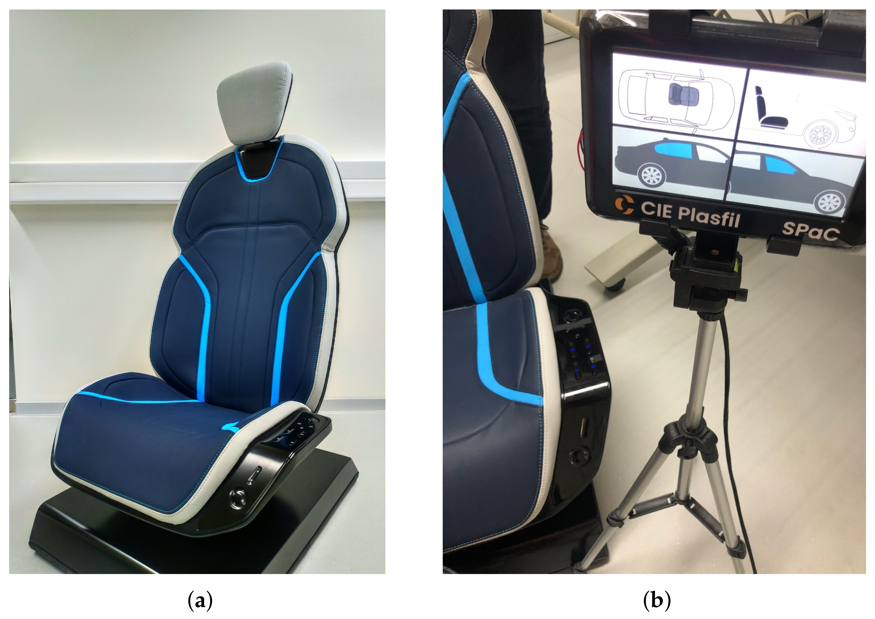
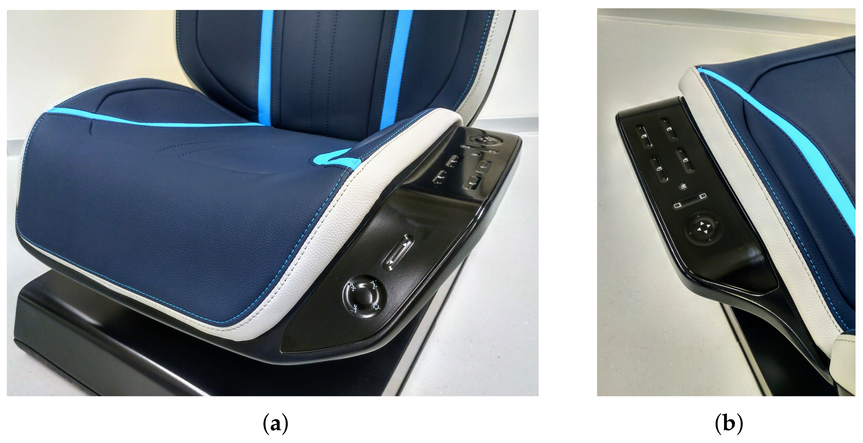
- Design of a futuristic car seat with integrated controls;
- Development, implementation and testing of a functional prototype to control the opening and closing of car side windows and the position of the car seats.
2. Materials and Methods
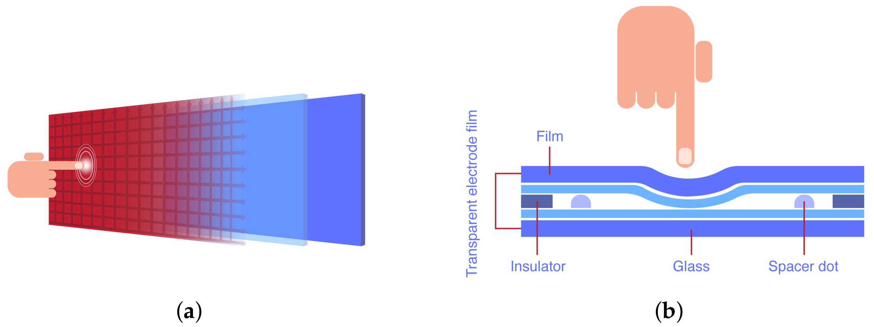
2.1. Touch Sensors for Activating Functions in Polymers


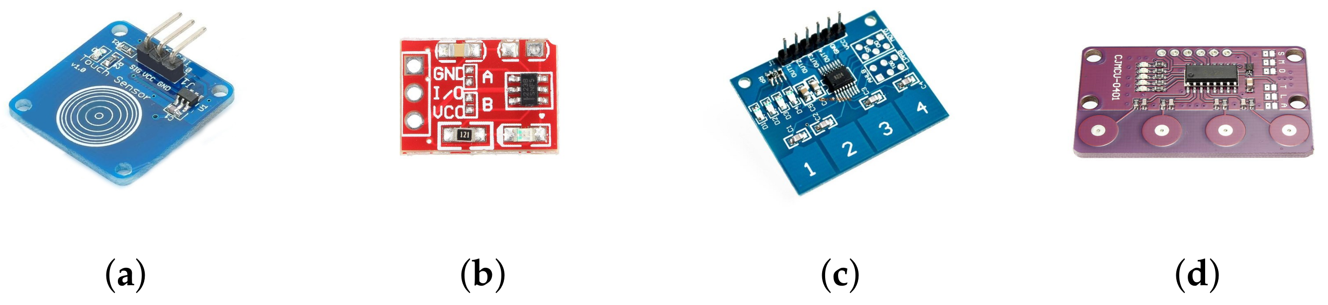
| Sensor # | Int. Circuit | Pad | Type | Datasheet |
|---|---|---|---|---|
| Sensor 1 | TTP223-B | Circular | 1 Channel | https://datasheet.lcsc.com/szlcsc/TTP223-BA6_C80757.pdf (accessed on July 13 2020) |
| Sensor 2 | TTP223N-B | Squared | 1 Channel | https://datasheet.lcsc.com/szlcsc/TTP223-BA6_C80757.pdf (accessed on 13 July 2020) |
| Sensor 3 | TTP224 | Squared | 4 Channels | https://download.mikroe.com/documents/datasheets/ttp224.pdf (accessed on 13 July 2020) |
| Sensor 4 | 0401-8224 | Circular | 4 Channels | Clone TTP224 |
| Sensor | Polymer | Description | Thickness (mm) | Test Number | Hits | Effectiveness | Assessment |
|---|---|---|---|---|---|---|---|
| Sensor 1 | PC ABS | Taroblend 66 | 2.5 | 30 | 30 | 100.00% | Approved |
| Sensor 1 | PA6GF30 | Ultramid B3E2G6 | 2.5 | 30 | 30 | 100.00% | Approved |
| Sensor 1 | PPTD20 | Hostacom TRC 352N | 2.5 | 30 | 29 | 96.67% | Approved |
| Sensor 1 | PP | Sabic PHC3181 | 2.5 | 30 | 29 | 96.67% | Approved |
| Sensor 1 | PA6 | Badamid B70S Natur | 2.5 | 30 | 29 | 96.67% | Approved |
| Sensor 2 | PC ABS | Taroblend 66 | 2.5 | 30 | 30 | 100.00% | Approved |
| Sensor 2 | PA6GF30 | Ultramid B3E2G6 | 2.5 | 30 | 30 | 100.00% | Approved |
| Sensor 2 | PPTD20 | Hostacom TRC 352N | 2.5 | 30 | 30 | 100.00% | Approved |
| Sensor 2 | PP | Sabic PHC3181 | 2.5 | 30 | 30 | 100.00% | Approved |
| Sensor 2 | PA6 | Badamid B70S Natur | 2.5 | 30 | 29 | 96.67% | Approved |
| Sensor 3 | PC ABS | Taroblend 66 | 1.8 | 30 | 29 | 96.67% | Approved |
| Sensor 3 | PA6GF30 | Ultramid B3E2G6 | 1.8 | 30 | 30 | 100.00% | Approved |
| Sensor 3 | PPTD20 | Hostacom TRC 352N | 1.8 | 30 | 29 | 96.67% | Approved |
| Sensor 3 | PP | Sabic PHC3181 | 1.8 | 30 | 30 | 100.00% | Approved |
| Sensor 3 | PA6 | Badamid B70S Natur | 1.8 | 30 | 30 | 100.00% | Approved |
| Sensor 4 | PC ABS | Taroblend 66 | 1.8 | 30 | 30 | 100.00% | Approved |
| Sensor 4 | PA6GF30 | Ultramid B3E2G6 | 1.8 | 30 | 30 | 100.00% | Approved |
| Sensor 4 | PPTD20 | Hostacom TRC 352N | 1.8 | 30 | 30 | 100.00% | Approved |
| Sensor 4 | PP | Sabic PHC3181 | 1.8 | 30 | 29 | 96.67% | Approved |
| Sensor 4 | PA6 | Badamid B70S Natur | 1.8 | 30 | 30 | 100.00% | Approved |
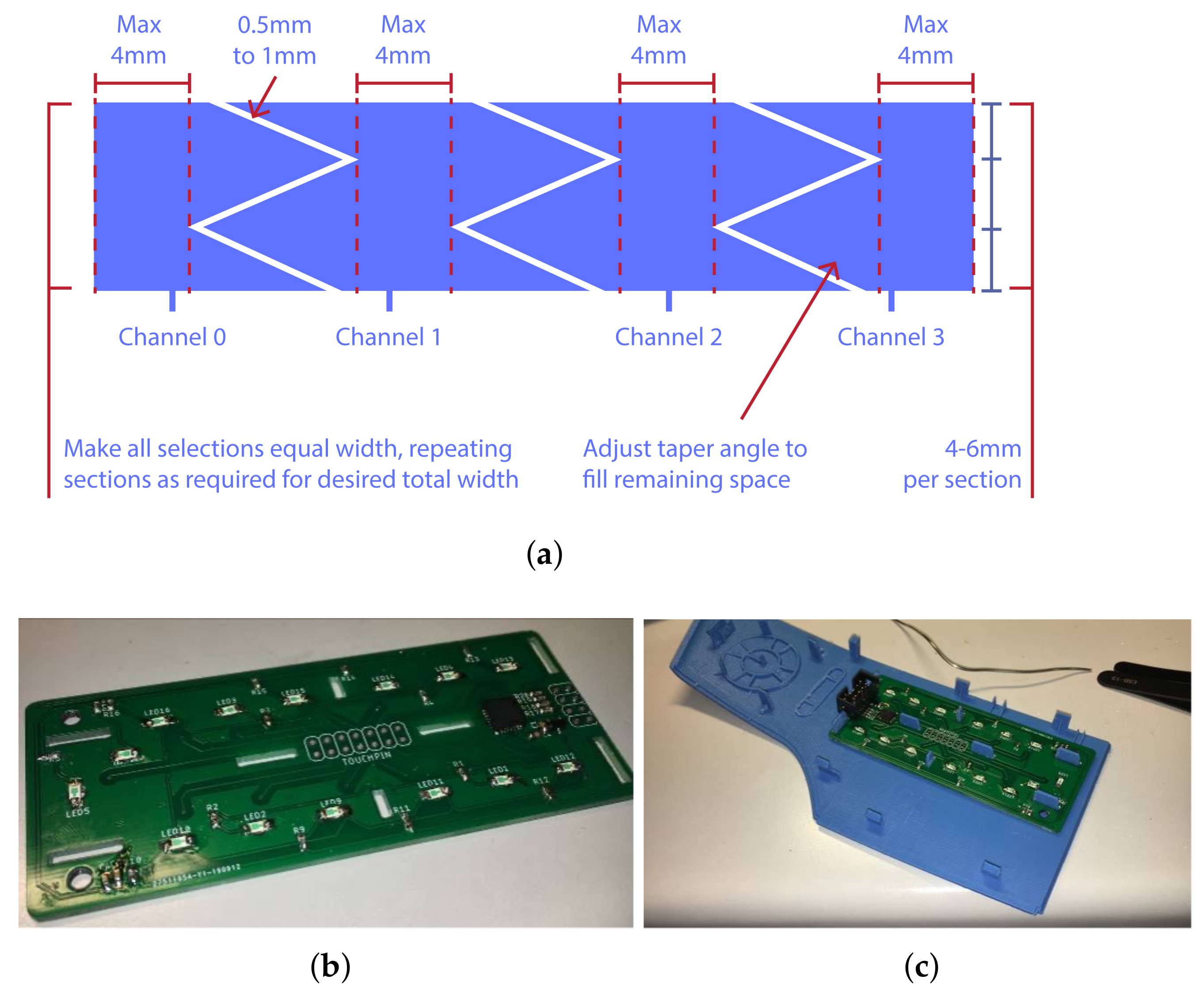
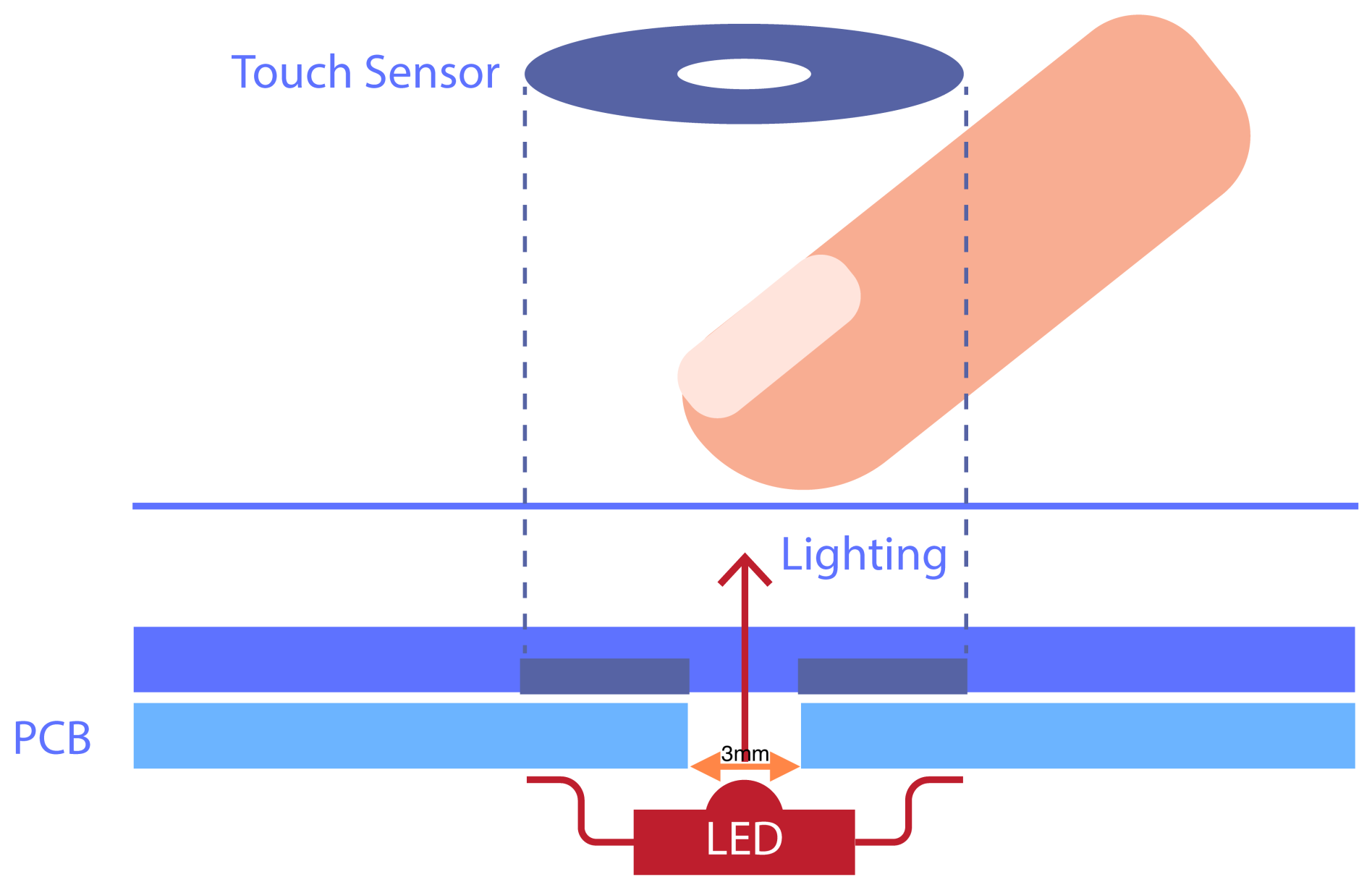
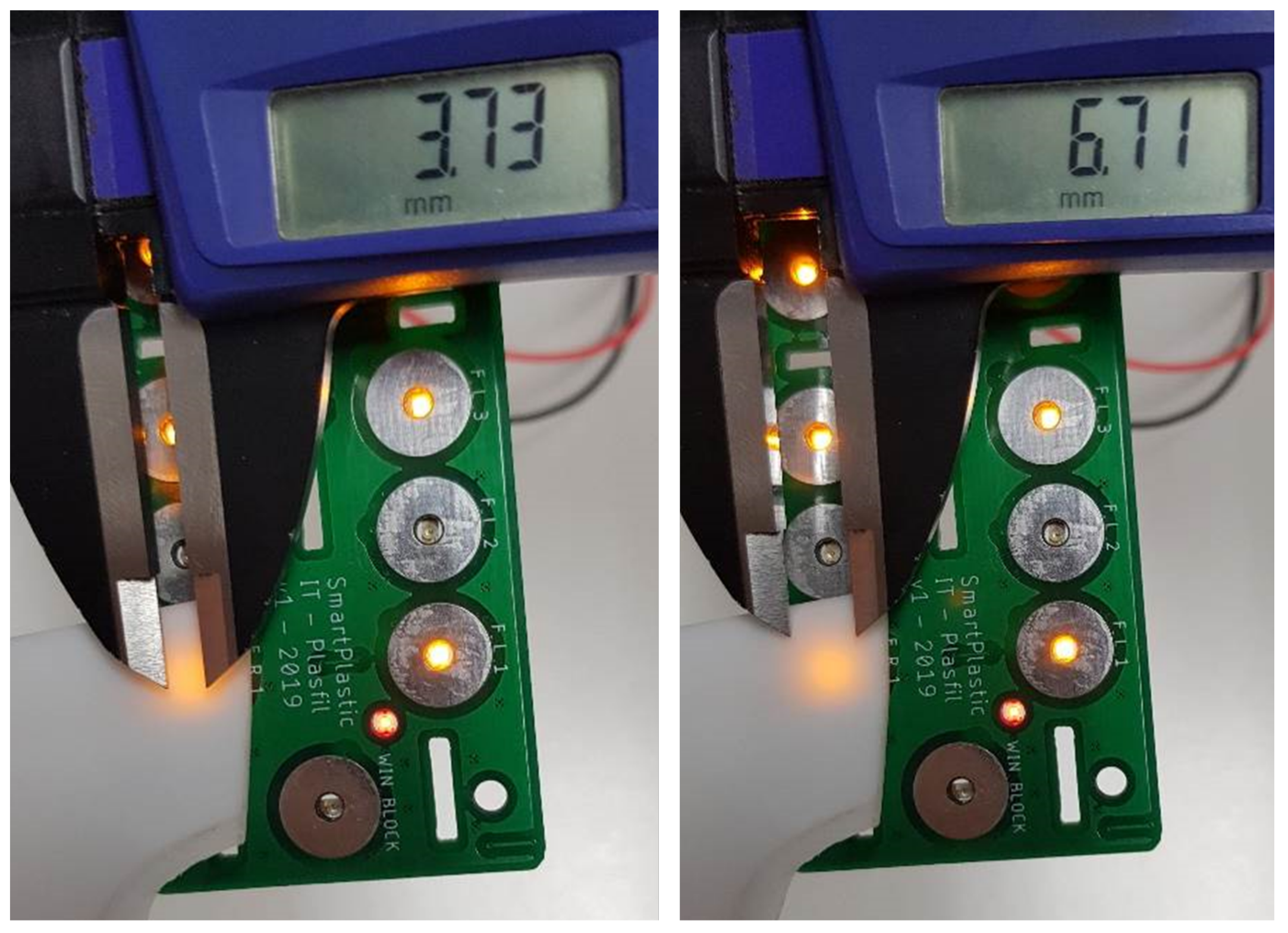
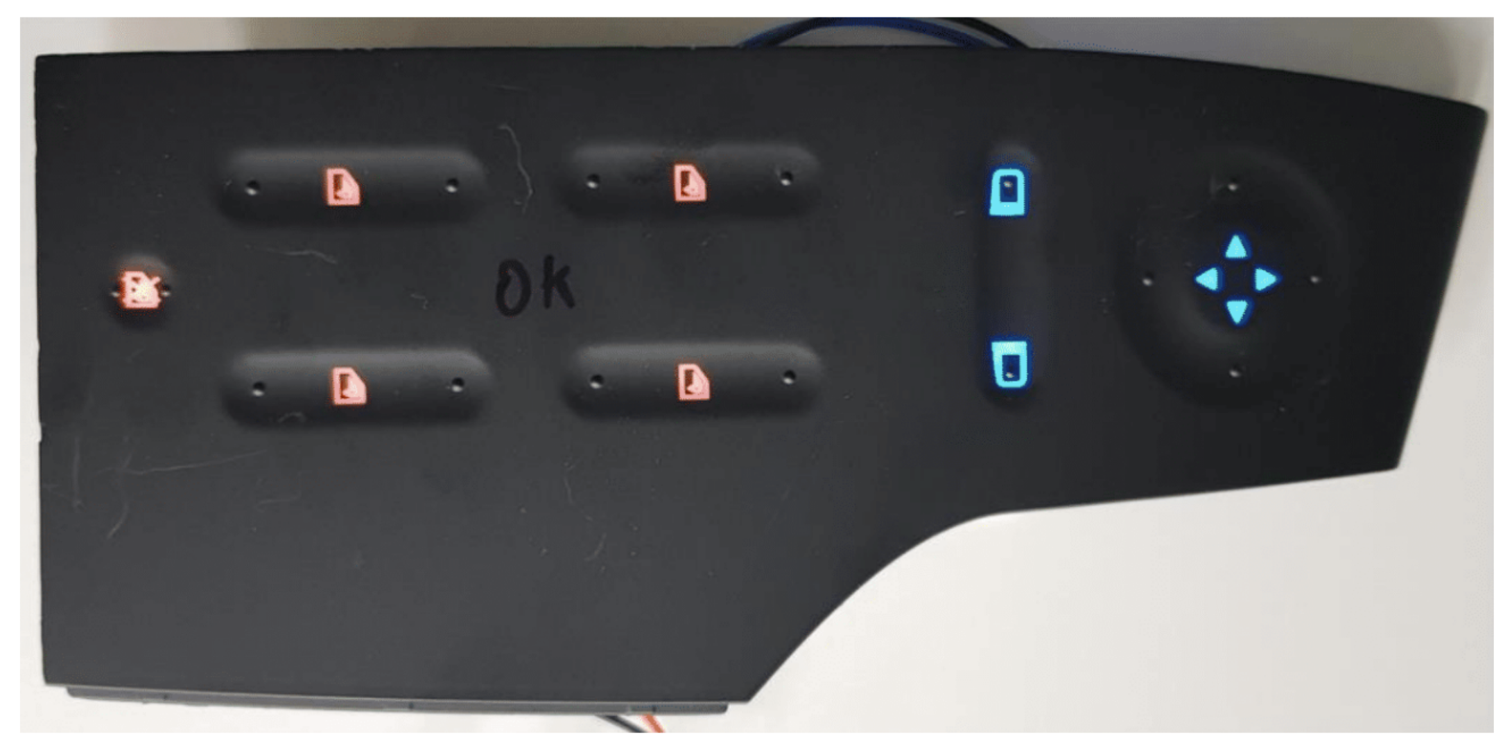
2.2. Touch Surface Backlighting
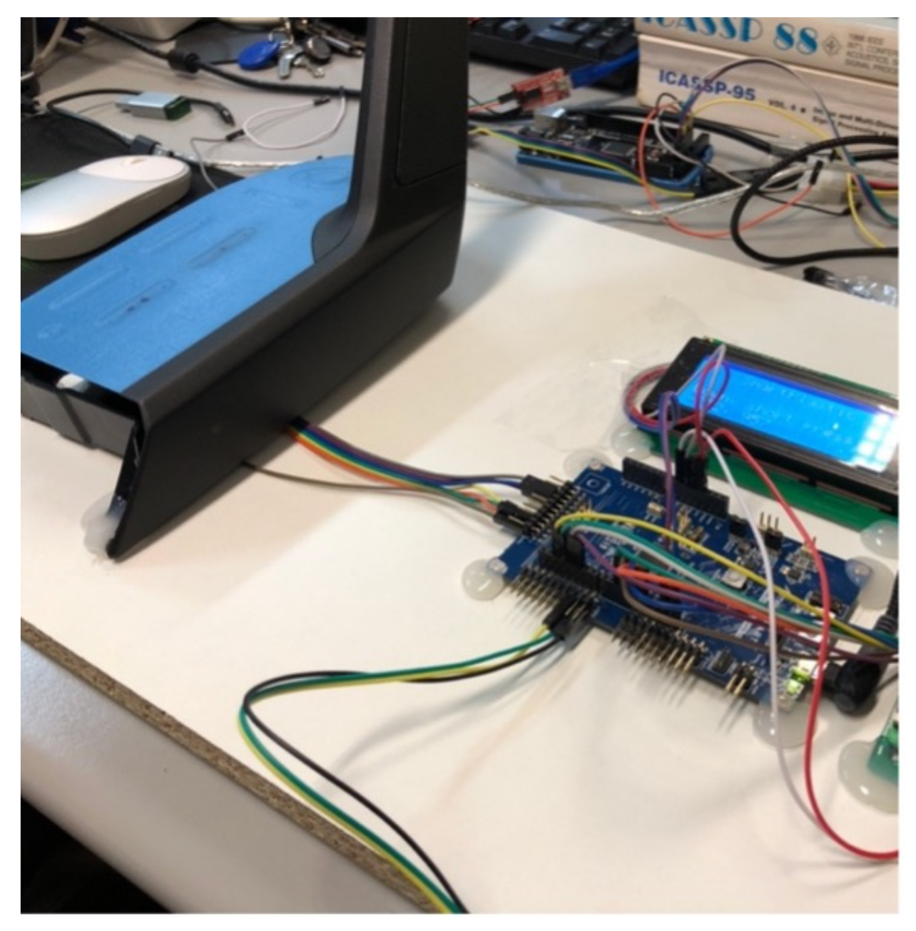
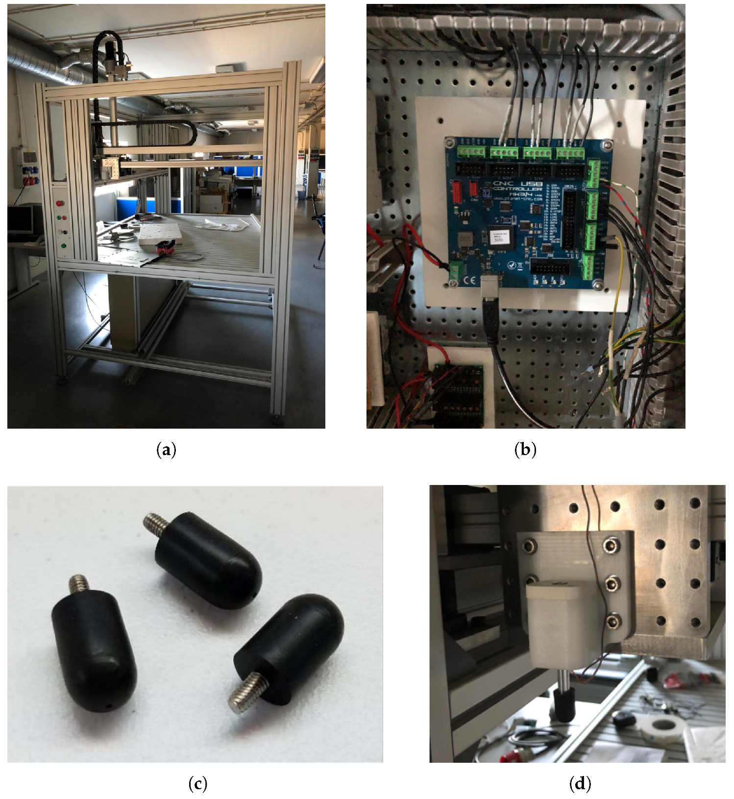
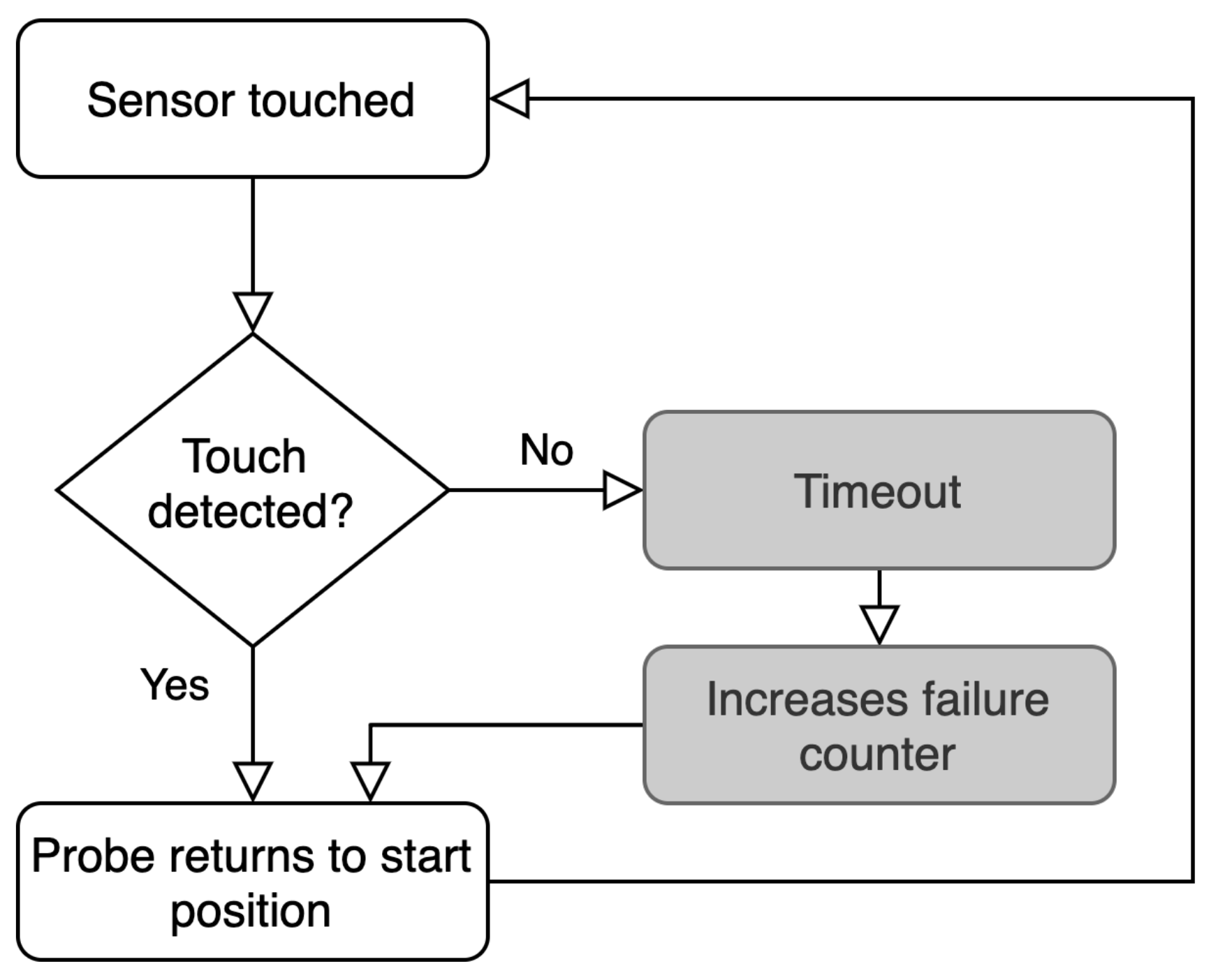
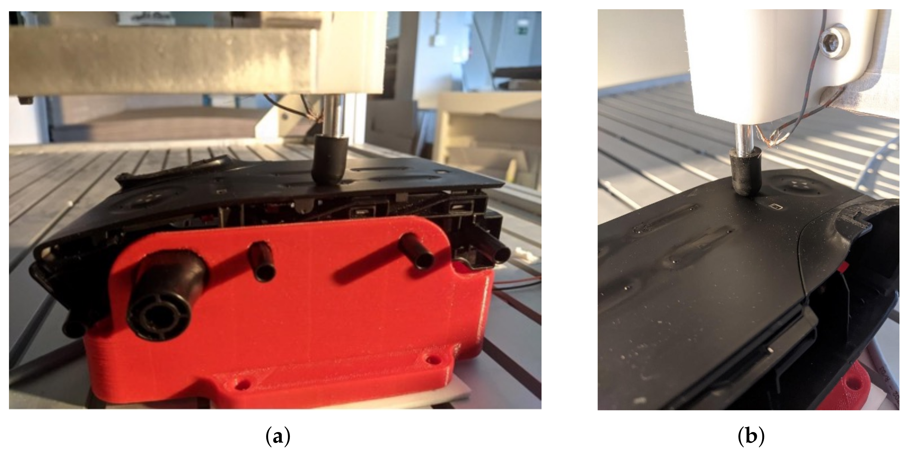
2.3. Validation and Reliability
- Move the probe to the initial position (2 cm above the sensor);
- Move the probe down 2 cm (touching the sensor);
- Wait for a digital signal on the CNC controller’s input, warning that a touch was detected;
- If the signal comes within 5 s, register this iteration as a success; otherwise, mark as a failure;
- Move the probe up 2 cm (no longer touching the sensor);
- Repeat the process from 2.
2.4. Comparing New and Current Paradigms
3. Implementation and Results
4. Discussion
4.1. Conclusions of This Study
- Innovative touch-based technology for controlling functionalities inside the car cabin;
- Thousands of cycles automatic reliability test and validation of touch-based sensors;
- Novel and appealing design of the cabin of self-driving cars;
- Moving control buttons and features to other parts of the cabin instead of the doors and central panel;
- More natural and intuitive human-machine interaction similar to the one used in mobile phones;
- Scalable and flexible addition of new functionalities via software technology;
- Retro-compatible technology;
- Supported by versatile communication protocols;
- The same low-cost solution can be incorporated into cars of distinct segments.
4.2. Future Research Directions
Author Contributions
Funding
Acknowledgments
Conflicts of Interest
Abbreviations
| SPaC | Smart Plastic Cover |
| LCD | Liquid-Crystal Display |
| ADC | Analog-to-Digital Converter |
| DAC | Digital-to-Analog Converter |
| CAN | Controller Area Network |
| LIN | Local Interconnect Network |
| PCB | Printed Circuit Board |
| ECU | Engine Control Unit |
| MTBF | Mean Time Between Failures |
| OEM | Original Equipment Manufacturer |
| MDPI | Multidisciplinary Digital Publishing Institute |
| FEDER | Fundo Europeu de Desenvolvimento Regional (Portugal) |
References
- Ji, K.; Orsag, M.; Han, K. Lane-Merging Strategy for a Self-Driving Car in Dense Traffic Using the Stackelberg Game Approach. Electronics 2021, 10, 894. [Google Scholar] [CrossRef]
- Park, M.; Kim, H.; Park, S. A Convolutional Neural Network-Based End-to-End Self-Driving Using LiDAR and Camera Fusion: Analysis Perspectives in a Real-World Environment. Electronics 2021, 10, 2608. [Google Scholar] [CrossRef]
- Talpes, E.; Sarma, D.D.; Venkataramanan, G.; Bannon, P.; McGee, B.; Floering, B.; Jalote, A.; Hsiong, C.; Arora, S.; Gorti, A. Compute solution for Tesla’s full self-driving computer. IEEE Micro 2020, 40, 25–35. [Google Scholar] [CrossRef]
- Driverless Cars Are Coming—A Paradigm Shift. Available online: https://www.computer.org/publications/tech-news/neal-notes/driverless-cars-are-coming-a-paradigm-shift (accessed on 17 August 2020).
- Eliot, L. AI Self-Driving Cars Consonance: Practical Advances in Artificial Intelligence and Machine Learning; LBE Press Publishing: New York, NY, USA, 2020. [Google Scholar]
- Morales-Alvarez, W.; Sipele, O.; Léberon, R.; Tadjine, H.H.; Olaverri-Monreal, C. Automated Driving: A Literature Review of the Take over Request in Conditional Automation. Electronics 2020, 9, 2087. [Google Scholar] [CrossRef]
- Autonomous Vehicles Will Create a Radical Paradigm Shift in Vehicle Design. Available online: https://www.automotive-fleet.com/159798/autonomous-vehicles-will-create-a-radical-paradigm-shift-in-vehicle-design (accessed on 12 June 2020).
- Krenicky, T.; Ruzbarsky, J. Alternative Concept of the Virtual Car Display Design Reflecting Onset of the Industry 4.0 into Automotive. In Proceedings of the IEEE 22nd International Conference on Intelligent Engineering Systems (INES), Las Palmas de Gran Canaria, Spain, 21–23 June 2018; pp. 407–412. [Google Scholar]
- Alves, C.; Custódio, T.; Silva, P.; Silva, J.; Rodrigues, C.; Lourenço, R.; Pessoa, R.; Moreira, F.; Marques, R.; Tomé, G.; et al. smartPlastic: Innovative Touch-Based Human-Vehicle Interface Sensors for the Automotive Industry. Electronics 2021, 10, 1223. [Google Scholar] [CrossRef]
- Kouba, S.; Dickson, N. Intuitive Touch Technologies—Semiconductor-Based Electronic Components and their Integration. Auto Tech Rev. 2016, 5, 38–43. [Google Scholar] [CrossRef]
- Rodríguez-Machorro, J.C.; Ríos-Osorio, H.; Águila-Rodríguez, G.; Herrera-Aguilar, I.; González-Sánchez, B.E. Development of capacitive touch interfaces. In Proceedings of the International Conference on Electronics, Communications and Computers (CONIELECOMP), Cholula, Mexico, 22–24 February 2017; pp. 1–8. [Google Scholar]
- Park, J.K.; Lee, C.J.; Kim, J.T. Analysis of multi-level simultaneous driving technique for capacitive touch sensors. Sensors 2017, 17, 2016. [Google Scholar] [CrossRef] [PubMed] [Green Version]
- Brasseur, G. Design rules for robust capacitive sensors. IEEE Trans. Instrum. Meas. 2003, 52, 1261–1265. [Google Scholar] [CrossRef] [Green Version]
- Kim, J.; Song, W.; Jung, S.; Kim, Y.; Park, W.; You, B.; Park, K. Capacitive Heart-Rate Sensing on Touch Screen Panel with Laterally Interspaced Electrodes. Sensors 2020, 14, 3986. [Google Scholar] [CrossRef] [PubMed]
- Capacitive Touch Sensor Design Guide. Available online: http://ww1.microchip.com/downloads/en/Appnotes/Capacitive-Touch-Sensor-Design-Guide-DS00002934-B.pdf (accessed on 13 July 2020).
- Seo, S.-H.; Park, J.-H.; Hwang, S.-H.; Jeon, J.W. 3-D Car Simulator for Testing ECU Embedded Systems. In Proceedings of the SICE-ICASE International Joint Conference, Busan, Korea, 18–21 October 2006; pp. 550–554. [Google Scholar]
- Coanda, H.-G.; Ilie, G. Design and implementation of an embedded system for data transfer in a car using CAN protocol. In Proceedings of the 12th International Conference on Electronics, Computers and Artificial Intelligence (ECAI), Bucharest, Romania, 25–27 June 2020; pp. 1–4. [Google Scholar]
- Elshaer, A.M.; Elrakaiby, M.M.; Harb, M.E. Autonomous Car Implementation Based on CAN Bus Protocol for IoT Applications. In Proceedings of the 13th International Conference on Computer Engineering and Systems (ICCES), Cairo, Egypt, 18–19 December 2018; pp. 275–278. [Google Scholar]
- Design with Surface Sensors for Touch Sensing Applications on MCUs. Available online: https://www.st.com/resource/en/application_note/dm00087990-design-with-surface-sensors-for-touch-sensing-applications-on-mcus-stmicroelectronics.pdf (accessed on 10 October 2019).
- ATtiny3216/3217–Datasheet. Available online: https://ww1.microchip.com/downloads/en/DeviceDoc/ATtiny3216-17-DataSheet-DS40002205A.pdf (accessed on 4 February 2021).
- Del Guerra, M.; Coelho, R.T. Development of a low cost Touch Trigger Probe for CNC Lathes. J. Mater. Process. Technol. 2006, 179, 117–123. [Google Scholar] [CrossRef]
- AlmaDesign: Managing Process and Culture in a Design Studio. Available online: https://www.almadesign.pt/studio (accessed on 17 December 2019).
- Fleming, B. Advances in Automotive Electronics [Automotive Electronics]. IEEE Veh. Technol. Mag. 2015, 10, 4–11. [Google Scholar] [CrossRef]
- The Future of the Car: A Paradigm Shift of the Century. Available online: https://autocrypt.io/future-of-car-paradigm-shift-of-the-century/ (accessed on 7 June 2021).
- Liu, S.; Li, L.; Tang, J.; Wu, S.; Gaudiot, J.-L. Creating Autonomous Vehicle Systems, 2nd ed.; Morgan & Claypool Publishers: Ulverston, UK, 2020. [Google Scholar]
- Hannaford, B.; Okamura, A.M. Haptics. In Springer Handbook of Robotics; Springer: Cham, Switzerland, 2016; pp. 1063–1084. [Google Scholar]
- Miedl, F.; Tille, T. 3-D surface-integrated touch-sensor system for automotive HMI applications. IEEE/ASME Trans. Mechatron. 2015, 21, 787–794. [Google Scholar] [CrossRef]
- Rao, Q.; Frtunikj, J. Deep Learning for Self-Driving Cars: Chances and Challenges. In Proceedings of the IEEE/ACM 1st International Workshop on Software Engineering for AI in Autonomous Systems (SEFAIAS), Gothenburg, Sweden, 28 May 2018; pp. 35–38. [Google Scholar]
- Xu, J.; Howard, A. How much do you Trust your Self-Driving Car? Exploring Human-Robot Trust in High-Risk Scenarios. In Proceedings of the IEEE International Conference on Systems, Man, and Cybernetics (SMC), Toronto, ON, Canada, 11–14 October 2020; pp. 4273–4280. [Google Scholar] [CrossRef]
- Gilpin, L.H. Anticipatory Thinking: A Testing and Representation Challenge for Self-Driving Cars. In Proceedings of the 55th Annual Conference on Information Sciences and Systems (CISS), Baltimore, MD, USA, 24–26 March 2021; pp. 1–2. [Google Scholar] [CrossRef]
- Mihalea, A.; Samoilescu, R.; Nica, A.C.; Trăscău, M.; Sorici, A.; Florea, A.M. End-to-end models for self-driving cars on UPB campus roads. In Proceedings of the IEEE 15th International Conference on Intelligent Computer Communication and Processing (ICCP), Cluj-Napoca, Romania, 5–7 September 2019; pp. 35–40. [Google Scholar] [CrossRef]


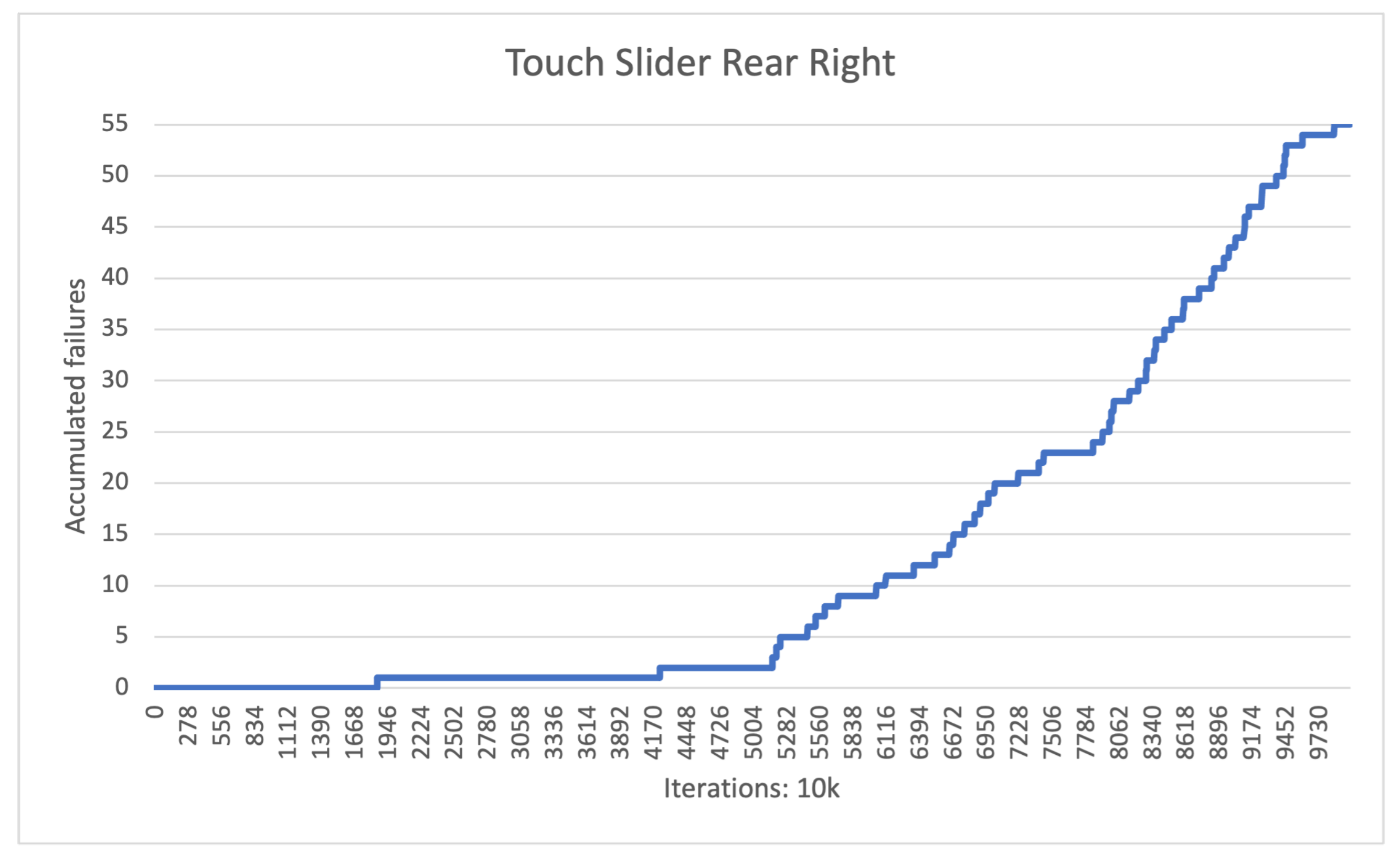
| Statistical Data | |
|---|---|
| Number of tests | 10,000 |
| Test duration (s) | 10,842 |
| Average response time (s) | 0.138 |
| Failure count | 55 |
| Failure rate | 0.55% |
| Failure distribution, Q1 | 1 |
| Failure distribution, Q2 | 1 |
| Failure distribution, Q3 | 21 |
| Failure distribution, Q4 | 22 |
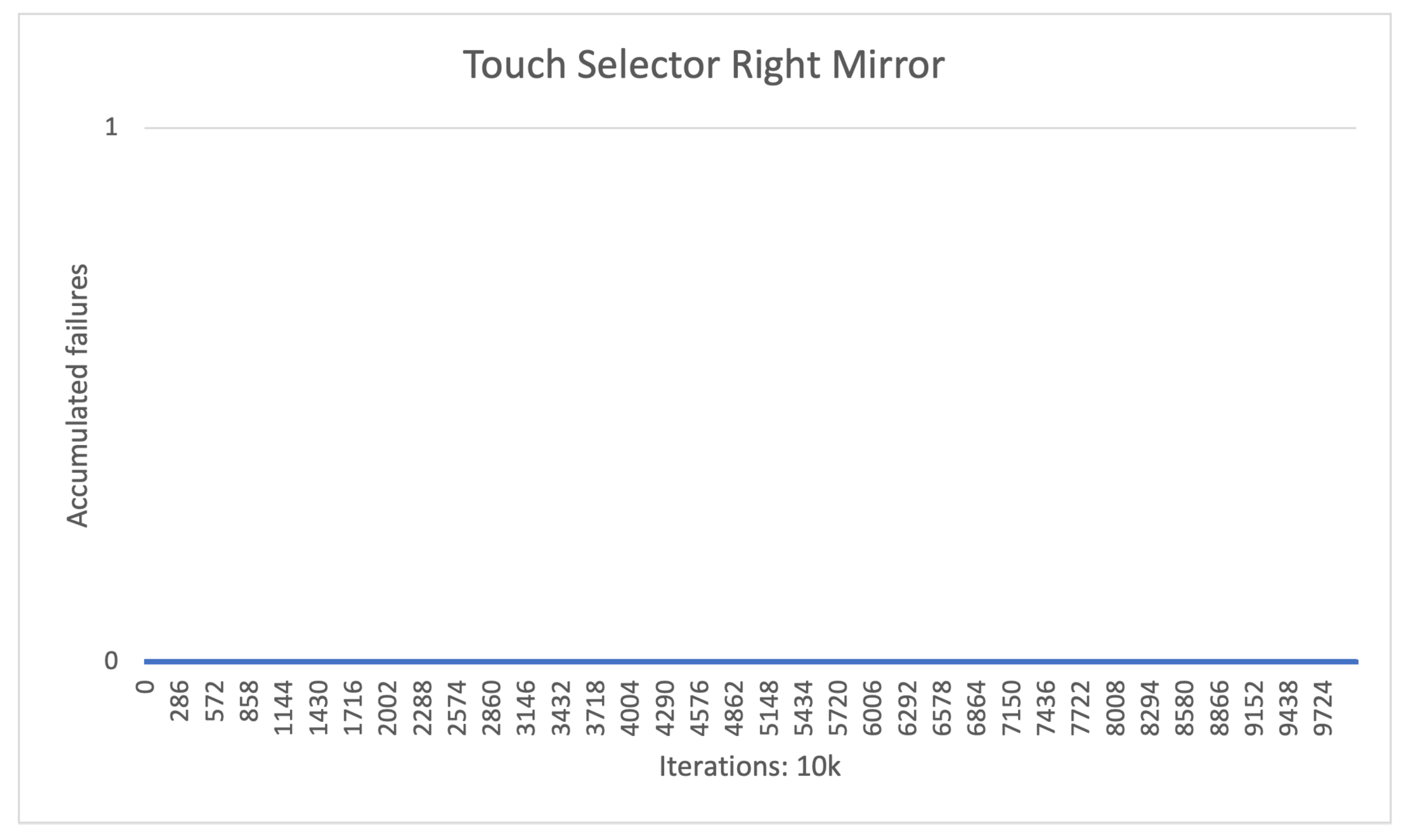
| Statistical Data | |
|---|---|
| Number of tests | 10,000 |
| Test duration (s) | 6909 |
| Average response time (s) | 0.18 |
| Failure count | 0 |
| Failure rate | 0% |
| Failure distribution, Q1 | 0 |
| Failure distribution, Q2 | 0 |
| Failure distribution, Q3 | 0 |
| Failure distribution, Q4 | 0 |
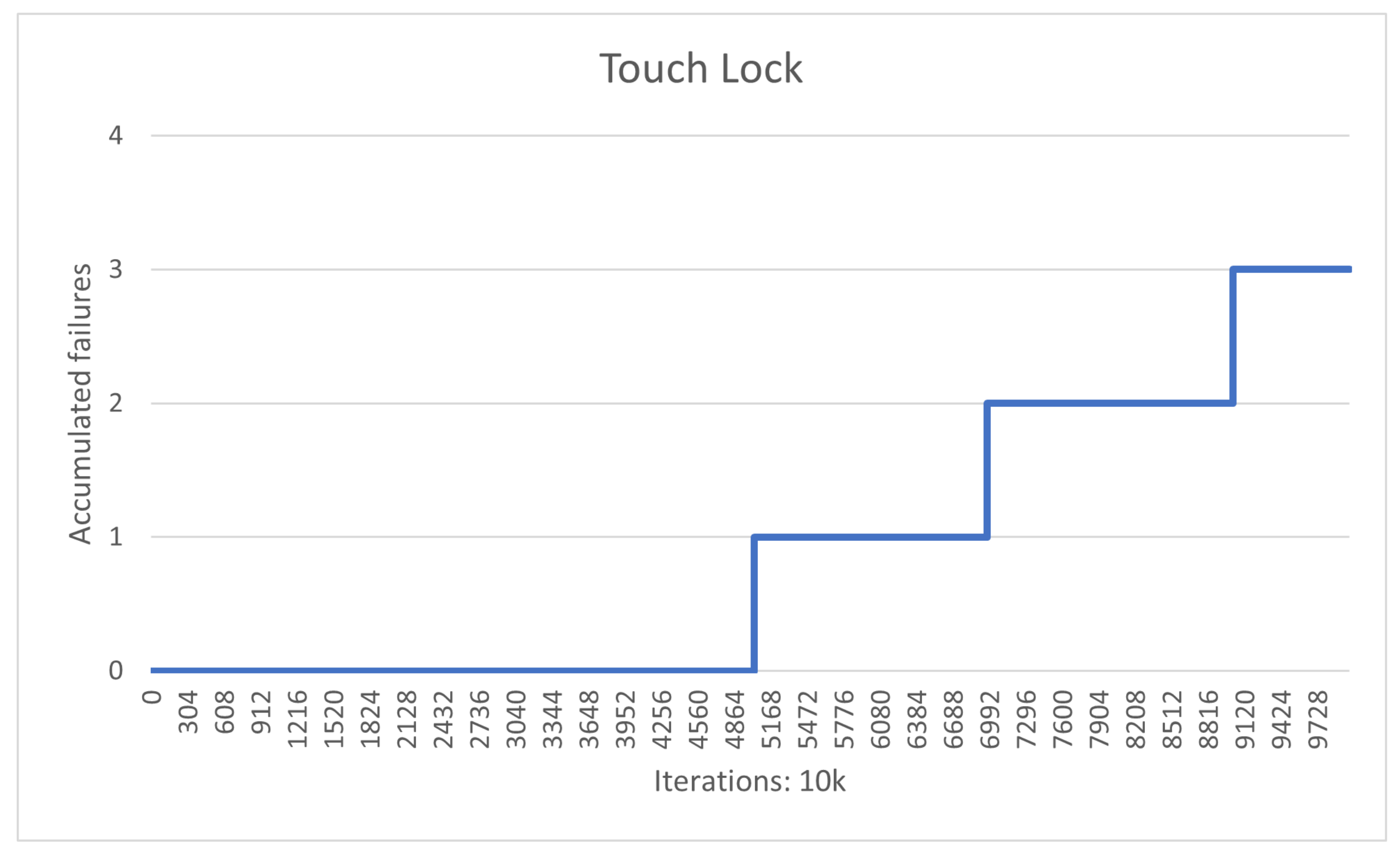
| Statistical Data | |
|---|---|
| Number of tests | 10,000 |
| Test duration (s) | 6820 |
| Average response time (s) | 0.172 |
| Failure count | 3 |
| Failure rate | 0.03% |
| Failure distribution, Q1 | 0 |
| Failure distribution, Q2 | 0 |
| Failure distribution, Q3 | 2 |
| Failure distribution, Q4 | 1 |
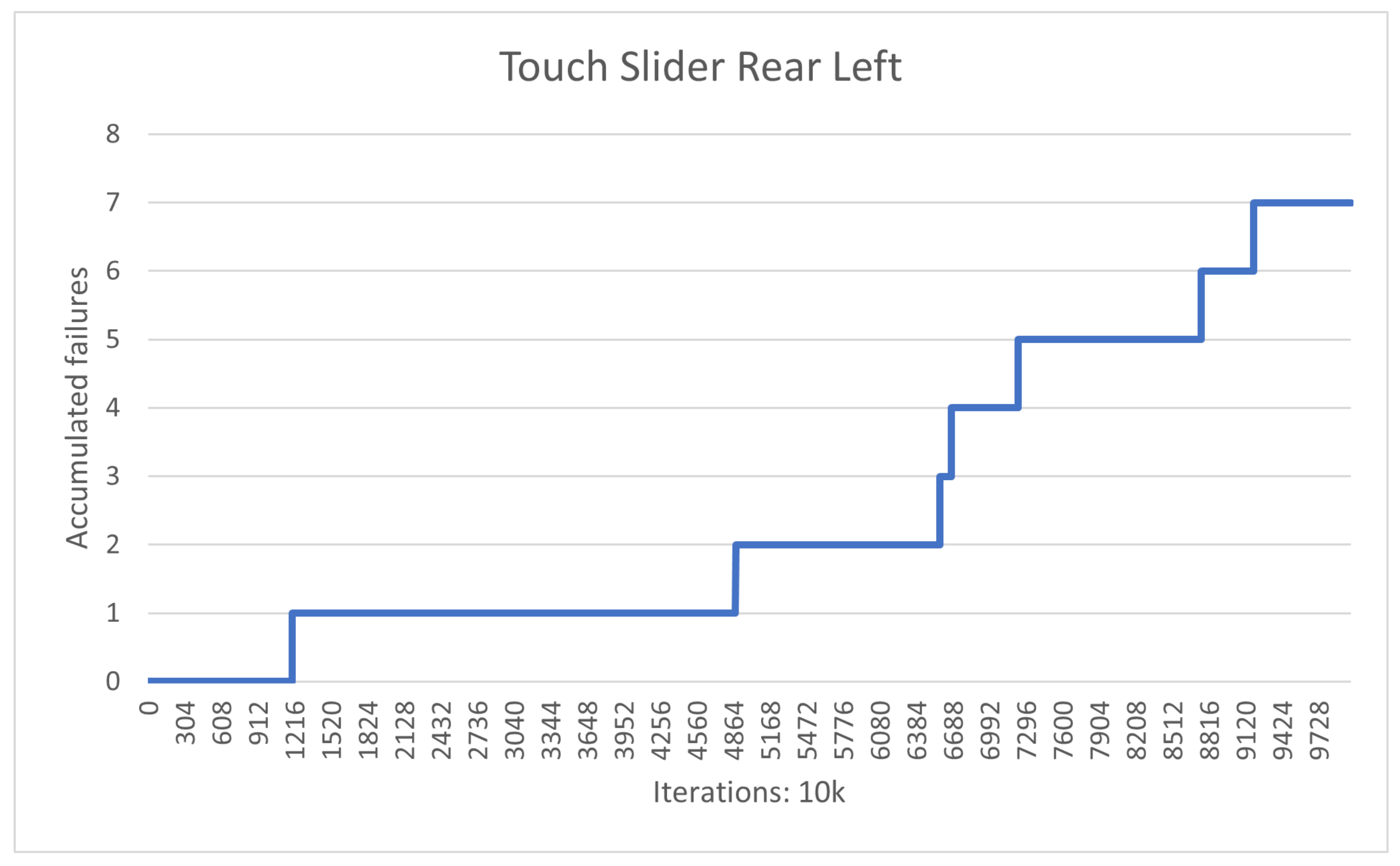
| Statistical Data | |
|---|---|
| Number of tests | 10,000 |
| Test duration (s) | 10,625 |
| Average response time (s) | 0.139 |
| Failure count | 7 |
| Failure rate | 0.07% |
| Failure distribution, Q1 | 1 |
| Failure distribution, Q2 | 1 |
| Failure distribution, Q3 | 3 |
| Failure distribution, Q4 | 2 |
Publisher’s Note: MDPI stays neutral with regard to jurisdictional claims in published maps and institutional affiliations. |
© 2021 by the authors. Licensee MDPI, Basel, Switzerland. This article is an open access article distributed under the terms and conditions of the Creative Commons Attribution (CC BY) license (https://creativecommons.org/licenses/by/4.0/).
Share and Cite
Custódio, T.; Alves, C.; Silva, P.; Silva, J.; Rodrigues, C.; Lourenço, R.; Pessoa, R.; Moreira, F.; Marques, R.; Tomé, G.; et al. A Change of Paradigm for the Design and Reliability Testing of Touch-Based Cabin Controls on the Seats of Self-Driving Cars. Electronics 2022, 11, 21. https://doi.org/10.3390/electronics11010021
Custódio T, Alves C, Silva P, Silva J, Rodrigues C, Lourenço R, Pessoa R, Moreira F, Marques R, Tomé G, et al. A Change of Paradigm for the Design and Reliability Testing of Touch-Based Cabin Controls on the Seats of Self-Driving Cars. Electronics. 2022; 11(1):21. https://doi.org/10.3390/electronics11010021
Chicago/Turabian StyleCustódio, Tiago, Cristiano Alves, Pedro Silva, Jorge Silva, Carlos Rodrigues, Rui Lourenço, Rui Pessoa, Fernando Moreira, Ricardo Marques, Gonçalo Tomé, and et al. 2022. "A Change of Paradigm for the Design and Reliability Testing of Touch-Based Cabin Controls on the Seats of Self-Driving Cars" Electronics 11, no. 1: 21. https://doi.org/10.3390/electronics11010021