Article

Towards Optimal Dissemination of Emergency Messages in Internet of Vehicles: A Dynamic Clustering-Based Approach

1
LINATI Laboratory, Department of Computer Science and Information Technology, Faculty of New Technologies of Information and Communication, University of Kasdi Merbah, Ouargla BP 511 30000, Algeria
2
Laboratory DRIVE EA 1859, University Bourgogne Franche Comté, 58000 Nevers, France
*
Author to whom correspondence should be addressed.
Electronics 2021, 10(8), 979; https://doi.org/10.3390/electronics10080979
Submission received: 15 March 2021 / Revised: 13 April 2021 / Accepted: 16 April 2021 / Published: 19 April 2021
(This article belongs to the Special Issue Emerging Wireless Vehicular Communications)

Abstract

:
In this paper, we target dissemination issues of emergency messages in a highly dynamic Internet of Vehicles (IoV) network. IoV is emerging as a new class of vehicular networks to optimize road safety as well as users’ comfort. In such a context, forwarding emergency messages through vehicle-to-vehicle communications (V2V) plays a vital role in enabling road safety-related applications. For instance, when an accident occurs, forwarding such information in real time will help to avoid other accidents in addition to avoiding congestion of network traffic. Thus, dissemination of emergency information is a major concern. However, on the one hand, vehicle density has increased in the last decade which may lead to several issues including message collisions, broadcast storm, and the problem of hidden nodes. On the other hand, high mobility of vehicles and hence dynamic changes of network topology result in failure of dissemination of emergency packets. To overcome these problems, we propose a new dissemination scheme of emergency packets by vehicles equipped with both DSRC and cellular LTE wireless communication capabilities. Our scheme is based on a dynamic clustering strategy, which includes a new cluster head selection algorithm to deal with the broadcast storm problem. Furthermore, our selection algorithm enables not only the election of the most stable vehicles as cluster heads, and hence their exploitation in forwarding the emergency information, but also the avoidance of packet collisions. We simulated our scheme in an urban environment and compared it with other data dissemination schemes. Obtained results show the efficiency of our scheme in minimizing collision and broadcast storm problems, while improving latency, packet delivery ratio and data throughput, as compared to other schemes.

1. Introduction

The emerging era of the Internet of Things (IoT) is transforming conventional Vehicular Ad-hoc Networks (VANET) into a new paradigm, named Internet of Vehicles (IoV) [1,2]. IoV plays a vital role in forming a dynamic network of connected vehicles for optimizing the main operations of an Intelligent Transport System (ITS) [3,4]. IoV enables efficient information sharing between vehicles as well as other network entities [5]. Figure 1 shows various communication types of IoV including V2V: Vehicle-to-Vehicle, V2R: Vehicle-to-Road, V2P: Vehicle to Pedestrian, V2I: Vehicle to Infrastructure, V2H: Vehicle to Home, and V2G: Vehicle to Grid or Vehicle to Green. The V2X has promising benefits in providing efficient and reliable bulky communications [6,7]. Thus, this makes IoV a key enabler of a wide range of unprecedented applications related to road safety, traffic management, and travel comfort [8]. In particular, IoV-enabled applications help avoid road accidents, detect less congested itineraries, and reduce air pollution and fuel consumption.
To enable these applications, vehicles in IoV are usually equipped with both Dedicated Short-Range Communications (DSRC) for short range wireless communications, and cellular LTE for long range communications. Integrating these two radio technologies, as a heterogeneous solution, is promising, in complementing each other and supporting V2X applications and their various requirements [9,10,11].
Besides, the number of vehicles is increasing dramatically on the road in recent years. This is mainly due to population growth in addition to the number of vehicles being manufactured daily. However, this increasing number has led to more traffic congestion, as well as accidents. For instance, in the USA, six million accidents occur every year, and more than 90 people die due to accidents every day [12]. Moreover, according to the American Transportation Research Institute (ATRI) [13], traffic congestion costs $74.1 billion annually, $66.1 billion of which occurs in urban areas. In this context, connecting vehicles in IoV is a promising paradigm to reduce both traffic congestion and accidents, hence improving both road users’ safety and traffic efficiency through intelligent traffic control and management.
Data dissemination is a common mechanism to share traffic information among vehicles and road infrastructure, via V2V and V2I communications, respectively [14,15]. However, vehicles in VANET are highly mobile which may provide many challenges. Dynamic changes in network topology cause frequent network disconnections. Another issue that can occur is the broadcast storm problem. This consists of unnecessary broadcasting of the same information which introduces high communication delay and degrades the vehicles’ data throughput. Moreover, this behavior may produce the hidden node problem. Some vehicles do not receive the message because they are not in the communication range of the broadcasters. These issues may directly affect the performance of dissemination schemes for emergency messages. In this case, vehicles may not be informed by actual events (e.g., accidents or congestion) in real time. Therefore, these issues must be addressed when designing new schemes for emergency messages dissemination, and disseminating these messages in an efficient way is a major concern.
To overcome these issues, and to reduce the complexity of vehicle-to-everything (V2X) systems [16], one possible solution is to dynamically divide vehicles into clusters based on common attributes such as location, direction, speed, etc. [17,18,19]. In such clusters, the vehicles send messages only to the cluster head, to avoid the broadcast storm problem. The cluster head can then send these to other cluster heads or vehicle members.
In this paper, we propose a new real-time Emergency Message Dissemination approach in IoV networks, called EMD-IoV. Our approach is based on a clustering strategy to enable efficient and reliable data dissemination among vehicles, as well as road infrastructure. A cluster head selection algorithm is designed at the top of our clustering strategy to elect the most stable vehicles as cluster heads. Moreover, our approach considers vehicles equipped with a GPS and both DSRC and LTE wireless technologies. This aims to ensure that emergency information will be broadcast not only between vehicles (DSRC), but also to the road infrastructure (LTE) in order to inform the concerned authorities about events. Table 1 illustrates the abbreviations we used in this work.
The remainder of this paper is organized as follows. Section 2 introduces the background to IoV in addition to related works regarding data dissemination mechanisms. Our proposed approach is detailed in Section 3. In Section 4, we evaluate our proposal by simulation and we discuss results. Section 5 concludes the paper.

2. Literature Review

A range of work has been proposed in designing data dissemination schemes. These works can be classified into three main categories based on the wireless technology used: (i) DSRC-based Data dissemination, based only on DSRC technology for short range communication between vehicles, and thus without involving the road infrastructure. (ii) LTE-based Data dissemination, which aims to disseminate emergency information towards the concerned authorities through V2I communication and leveraging already deploying LTE eNodeB. (iii) Hybrid-based Data dissemination (DSRC/LTE) which combines both communication types, V2V and V2I.

2.1. DSRC-Based Data Dissemination

Nguyen et al. proposed a new dissemination strategy named Store Carry Forward (SCF) [20]. In SCF, vehicles store emergency messages locally and forward stored messages once a new neighbor is detected in the communication range. To check if the neighbor is new or not, the system compares the hash received from the beacon packet of those already stored. So, a predefined interval is used to store the messages. Afterwards, they will be deleted. This strategy adopts a novel SCF mechanism to deal with both broadcast storm and network partition challenges, while ensuring accurate information sharing among neighboring vehicles.
Latif et al. [21] proposed a reliable data dissemination scheme for a VANET scenario, to avoid the broadcast storm problem. This scheme selects only some nodes to forward packets, based on their geographical location. Following this approach, the farthest receiver from a sender will become the highest priority to be the forwarder. The node, receiving duplicate messages, before the expiration of its waiting time, stops waiting and deletes its stored packet. However, this approach may increase transmission delay, especially in a sparse density scenario.
Alsuhli et al. [22] proposed a clustering-based dissemination scheme for vehicular networks, called Double Head Clustering (DHC). The cluster head vehicles are selected based on multiple metrics: position, speed, signal-to-noise ratio (SNR), and link expiration time (LET). Then, selected CHs will be in charge of forwarding emergency packets. Similarly, Bello et al. [23] designed an enhanced weight-based clustering algorithm, where the CH is the node with the highest weight calculated on the basis of speed, distance, and connectivity level.
The authors of [24] were interested in improving dissemination of safety messages in VANETs, based on clustering architecture. In fact, the designed scheme comprises three main steps: Cluster Formation, Collision Avoidance and Safety Message Broadcasting. In their approach, the election of CH is based on mobility and connectivity.
Aissa et al. [25] proposed a new dissemination scheme based on a distributed clustering algorithm. In this scheme, the cluster heads are elected using fuzzy logic combining multiple attributes. The advantage of this algorithm is the creation of stable clusters by reducing re-clustering overheads and extending clusters’ lifetimes.

2.2. LTE-Based Data Dissemination

Feng et al. [26] proposed a new broadcast strategy for safety messages in VANET-cellular architecture. The proposed scheme does not rely on the deployment of RSUs or traffic density. It selects one node as relay through the exchange of short control packets. This scheme widely improves channel access efficiency in addition to avoiding redundant data in VANET.
Ebadinezhad et al. [27] proposed a clustering-based algorithm for IoV equipped with 5G communication technology. This algorithm is based on a metaheuristic ant colony to optimize the selection of cluster heads. This paper also proposed another algorithm for mobility management. The main objectives of this algorithm are to select the most stable vehicles as CHs while considering network density.
Guangjin et al. [28] designed a new LTE-V2X-based data dissemination scheme to collect data on road traffic accidents. The reported traffic incidents will be sent in real-time to IoV platform in order to help drivers in avoiding congestion and improving their driving experience.
Aadil et al. [29] addressed the stability of IoV topology when disseminating emergency data. They propose a clustering-based architecture leveraging the dragonfly optimization algorithm. The proposed scheme is mobility aware and enables stable data dissemination. In addition, it is also based on cellular communication in order to improve network availability.

2.3. Hybrid (DSRC/Cellular LTE) Based Data Dissemination

Lin et al. [30] proposed a new scheme to ensure timely emergency messages dissemination, based on two wireless communication technologies. It uses the IEEE 802.11p to forward safety messages between vehicles (V2V), and LTE to send non-safety messages. The authors have shown the efficiency of this approach in significantly reducing congestion in the communication channels.
Wu et al. [31] studied the integration of LTE with DSRC in order to achieve content dissemination in VANETs. They proposed a two-level clustering scheme. In the first-level, cluster heads (CHs) collaborate to overcome MAC layer contention problem for V2V communications, while CHs within the second-level aim to form an optimal gateway between V2V and LTE.
Tseng et al. [32] proposed a stable clustering algorithm called CATRB. This uses the traffic regularity of buses to improve stability by decreasing the number of CH changes. while considering the mobility of vehicles such as speed, direction, and location. Indeed, it uses the fixed-route pattern of buses to estimate the space and time distribution of other cars in urban areas as a reference index. In an equilateral triangle, CATRB uses the centroid, circumcenter, and incenter to choose the most appropriate CH in the VANET. Obtained results show that selected CHs efficiently transmit their data to other vehicle members due to their location (in the center of the cluster).
On the other hand, authors in [33] propose a heuristic-based clustering algorithm for data dissemination in IoV. In this work, RSUs are in charge of cluster formation as well as CHs selection. The advantage of the proposed solution is its ability to elect secondary CHs which recover the unavailability of primary CHs.
Awais Ahmad et al. [34] proposed a hybrid data dissemination scheme for an Intelligent Transportation System, called Hybrid-VITS. This scheme enables route planning and data dissemination in real time using an Internet of things paradigm. In congestion situations, Hybrid-VITS combine VANET and 5G cellular networks to determine the optimal path using the shortest path algorithm. Moreover, a load balancing technique is also designed to avoid further congestion when determining new paths.
Table 2 shows a comparison study between the data dissemination approaches discussed above, according to several criteria such as strategy, communication type, CHs selection metrics, considered environment, tools for evaluation and targeted performance, etc. As we can observe, there are a wide range of works addressing data dissemination in VANET as well as IoV. However, few have integrated both LTE and DSRC technologies, in disseminating emergency information. In addition, we remark that the major works have focused on a specific and limited geographical area, without scalable approaches. Moreover, proposed CHs selection algorithms are affected directly by the high mobility as well as high density of such networks. Hence, to fill these gaps, our new approach is based on both DSRC and LTE technologies, to exploit these not only for efficient dissemination of emergency information in real-time, but also in selecting the most stable vehicles as CHs. Our approach will be scalable since it is performed in a large geographical area, and thus it is also tolerable for the high density of vehicles in an urban scenario.

3. Dynamic Clustering-Based Dissemination Approach

In this section, we detail our proposed scheme to disseminate emergency messages based on clustering architecture. We call our approach: Emergency Message Dissemination in IoV networks, EMD-IoV.

3.1. System Model and Assumptions

Our EMD-IoV approach enables selection of the best path in forwarding the emergency messages in an urban environment, and in real-time. This also enables a reduction in transmission delay and overheads while ensuring high coverage by selecting the best forwarder vehicles based on several networks’ metrics.
We consider an urban IoV scenario composed of n vehicles (nodes), and each vehicle has a unique identity ( i [ 1 , n ] ) . The vehicle network is modeled by an undirected graph G = ( V , E ) in the coverage area of LTE antenna ( e N o d e B i ) , where its vertices V = { v 1 ,     ,   v n } are the set of vehicles, and edges E represent a set of communication links between these vehicles. There is a direct communication link among vehicle i and e N o d e B i , if and only if vehicle i is in the transmission range of e N o d e B i .
  e ( v i , e N o d e B i ) E v i R e N o d e B i
There is a direct communication link e ( v i , v j ) E , if and only if vehicles i and j are in transmission range of each other. This also implies that the link between both nodes is bidirectional.
  e ( v i , v j ) E d i s ( v i , v j ) m i n ( R v i , R v j )
where R v i , R v j represent the maximum transmission range for vehicle v i , v j respectively. d i s ( v i , v j ) is the distance between vehicles v i , v j with is calculated by Euclidean distance ( E d ) , defined as follows:
E d ( v i , v j ) = ( x v i x v j ) 2 + ( y v i y v j ) 2
With each vehicle v i V is aware of its own location L v i ( x v i , y v i ) , velocity, and moving direction. We denote N ( v i ) as a subset of all single-hop neighbors within the radio range radius of a given vehicle v i , as follows:
N i = { v j V | ( v i , v j ) E }
Each vehicle v d uses road identifier “Road_ID” to filter any vehicle v s that is moving on another road or in the opposite direction, where all neighbor vehicles with the same road identifier “Road_ID” have the same direction.
Node degree: This = is the size of the set of single-hop neighbors of vehicle i , N i , where the degree of node i is defined as follows:
D v i = | N i |
The node degree represents its connectivity to the network.
Average Velocity Difference (AVD): A lower AVD of the vehicle relative to its neighbors indicates that the node is more stable in terms of its mobility. Let us assume that L v i ( x 1 , y 1 ) is the position of vehicle i at time T 1 and L v i ( x 2 , y 2 ) is the position of the same vehicle i at time T 2 . Δ d i is the distance traveled by vehicle i over time Δ t   ( Δ t = T 2 T 1 ) .
Δ d i = ( x 1 x 2 ) 2 + ( y 1 y 2 ) 2
Thus, the velocity v i of vehicle i over time Δ t is computed as:
v i = Δ d i Δ t  
Finally, the average relative velocity A R V i of node i is computed as:
A V D i = j = 1 , j i D v i | v i v j | D v i
Average Relative Distance (ARD) is the average relative distance between a vehicle and its neighbors. A vehicle that has a minimum A R D is closer to the center of its neighborhood. The A R D i   of vehicle i is computed as the cumulative mean square distance to its neighbors divided by its D v i , as follows:
A R D i = j = 1 , j i D v i ( x i x j ) 2 + ( y i y j ) 2 D v i
Further, we consider that all vehicles have two wireless interfaces: LTE and 802.11p. The IEEE 802.11p is used to establish V2V communications, while the LTE radio transceiver is used to communicate with eNodeB. In addition, each vehicle v i maintains information on its neighbors, e.g., direction, location, and neighborhood. Furthermore, there are two kinds of message in the system, beacon and emergency messages. We note that beacon packets are exchanged periodically and include vehicles’ location, speed, and direction information. Finally, let E v E be the set of communication links between v i and its neighbors N ( v i ) .
The objective of the proposed hybrid architecture is to efficiently forward data packets in a certain geographical region, with only a small delay and high percentage of vehicles successfully receiving packets. We aim also to minimize the number of elected CHs and ensure the cluster’s stability. The basic idea of our approach is to select the best path to forward the emergency messages from a source vehicle to a destination taking into account the optimal forwarding between both inter- and intra-geographical regions. Thus, a sender vehicle will forward the emergency messages to the appropriate next-hop vehicle based on the selected path, until the message is transmitted to its destination.
We also consider the following assumptions in designing our EMD-IoV approach:
  • Each vehicle in the network has a unique id.
  • Each vehicle can calculate its velocity and is able to deduce its current position using a GPS device.
  • Vehicles can discover others within their communication range through periodic beacon messages.
  • The urban scenario has two roads (one for each direction), and three lanes for each road.
  • Several LTE Antennas (eNodeB) with a transmission range of 1.5 km are installed every 3 km at the side of the intersection area, to cover the entire vehicular network.
Moreover, Figure 2 shows an overview of our EMD-IoV approach in urban scenarios, with its main components and actors including: Region Geo-Zoning, OBUs, Ordinary Cluster (OC), Gateway Cluster (GC), and Leader Cluster (LC).
  • OBU (On-Board Unit): A terminal element placed on the vehicle that offers wireless communication interfaces (IEEE 802.11p and LTE), between the vehicle and its nearby vehicles, and with LTE-V infrastructures.
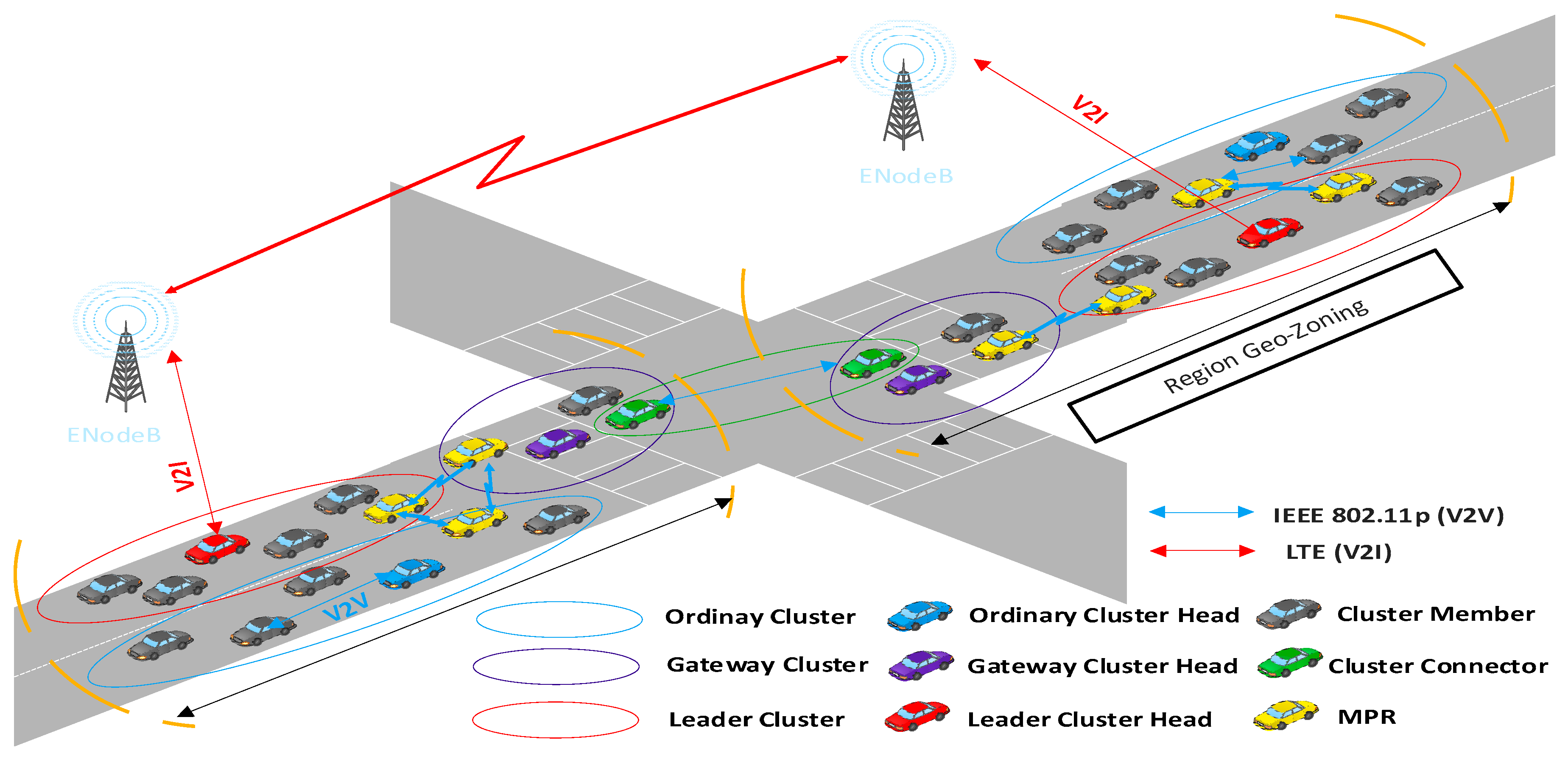
  • Region Geo-Zoning: the LTE infrastructure used in our EMD-IoV approach is responsible for data dissemination inside a geographical region (based on LTE eNodeB Antenna). We use LTE networks to provide low latency, high coverage, and robust mechanisms dealing with high vehicle mobility. The coverage area with eNodeB is specified as the urban geographical area in our approach, wherein virtual groups of vehicles are created with a unique ID for eNodeB.
  • Leader Cluster (LC): in charge of coordination and communication with other clusters and network infrastructures. Moreover, LC may perform other tasks, such as relaying information between nodes in the same cluster (intra-cluster communication) or between different clusters (inter-cluster communication). Compared with other nodes in the cluster, the LC also has other additional functions, such as data aggregation and channel access management.
  • Gateway Cluster (GC): a gateway cluster is a non-ordinary cluster located within the boundaries of the region which forwards the emergency message between regions via cluster connector (CC). Gateway Cluster (GC) selection is an important task of a Leader Cluster (LC). In the cluster gateway selection algorithm, the leader of the clusters chooses a set of suitable clusters to become cluster gateways. Gateways Cluster Heads (GCH) are the main participants in the delivery of data within regions.
  • Ordinary Cluster (OC): an ordinary group of vehicles that join a cluster according to their characteristics and similarities. OC is responsible for sending application-based information and data to the CH at specific time intervals.

3.2. Clustering Scheme

In this subsection, we present our clustering scheme in detail by introducing the following aspects:

3.2.1. Cluster State

Due to the high mobility of vehicles, in the clustering process the transition from one cluster state to another is driven by events. Indeed, all vehicles begin with an un-clustered vehicles (UV) state. The Un-clustered-Vehicles (UV) that are geographically close to each other establish Ordinary Clusters (OC). When an ordinary cluster has a good signal and communication link with the LTE antenna, it switches to the Leader Cluster (LC) state. However, if the OC is located within the boundaries of the region, and can communicate with the border OCs in the other region, it switches to Gateway Cluster (GC) state if this is approved by the LC. The cluster can again return to the OC state if its geographical location changes (cf. Figure 3).

3.2.2. Node State

Vehicles can assume several states during the clustering process. Initially, before starting the clustering process, all vehicles are in the un-clustered vehicle (UV) state. When transiting from one cluster to another cluster, a vehicle can be in the following states:
  • In an Ordinary Cluster (OC), the vehicle can be in three states. If the vehicle is located in the center of the cluster, it is the most qualified to act as a leader and takes the Ordinary Cluster Head (OCH) state. The rest of the nodes will be cluster members (CM), or Multi Point Relay (MPR) if they are located on the edges of the cluster.
  • When a vehicle transits from OC to LC, it switches from the OCH state to a Leader Cluster Head (LCH) state, otherwise it will be a CM or MPR in the new cluster. A CM can also transit to the MPR state, while the latter can also convert to a CM state.
  • When an OC becomes a Gateway Cluster (GC), OCH becomes a Gateway Cluster Head (GCH); otherwise, it can be in a CM state or in an MPR state, whereas CM can take the Cluster Connector (CC) state if it can communicate with a vehicle in the GC located in another region. MPR can also switch to CM or CC states. The possible transition from one state to another is triggered by events as illustrated in Table 3.

3.2.3. Clusters Formation

In this sub-section, we show how vehicle clusters are formed in our EMD-IoV approach.

Neighbor Discovery

In the network initialization phase, when a vehicle decides to join the network it should turn on its communication system and update its state to an un-clustered node. Then, it should announce its existence to the neighboring vehicles. To do so, the new vehicle broadcasts a periodic “Hello message” to its one-hop neighbors, while simultaneously receiving similar messages from them. The periodic “hello message” contains the necessary information to perform the clustering process (see Figure 4). Firstly, all sending vehicles put their main information including position, role, and velocity into the “hello message”. At receiving a “hello message” from all its one-hop neighbors, each vehicle calculates its Reliability V R v i by using the formulas (Equations (10) and (11)) to switch to the cluster’s formation phase.
Vehicle Reliability (VR): In our proposed approach we represent the vehicle reliability of the vehicle relative to its neighbors as it is used in clustering. This depends on the ARD variation rate. Let us assume that A R D v i ( t 1 ) is the average relative distance of vehicle v i at time t 1 and A R D v i ( t 2 ) is the average relative distance of vehicle v i at time t 2 . The link Reliability L R v i ( T ) of vehicle i over a time T ( T = t 2 t 1 ) is calculated as follows:
L R v i ( T ) = | A R D v i ( t 1 ) A R D v i ( t 2 )   |
Therefore, the Vehicle Reliability V R v i of vehicle v i is calculated based on link reliability parameters, as follows:
VR v i = L R v i ( T ) D v i + ln ( 1 A V D v i v max ) ) 2 + A R D v i D i max
where D i m a x is the maximum distance between vehicle v i and its neighbors. v m a x is the maximum velocity allowed on the road. Thus, the first term of this equation leads to choosing a vehicle with high link reliability, while the second term helps us to deduce the most stable vehicle in terms of velocity and distance from its neighbors. Hence, a high VRvi rate implies that the vehicle is suitable to be selected as OCH.

Ordinary Cluster and Ordinary Cluster Head

During a specified waiting time (Ϥ) period, each vehicle v i waits for the arrival of a new vehicle to register it in the neighbor’s list and recalculates. In the event that no vehicle v i registers a new neighboring vehicle during the period of wait time, a new election message “Elect Msg” will be broadcast by the vehicle v i in order to elect Ordinary Cluster. All neighbor vehicles of vehicle v i will receive the elect message, and even if their wait times have not expired the election starts. The frame format of “Elect Message” used in our approach is shown in Figure 5, which mainly includes as source information the message information. The source information includes the identifier Vehicle_ID of the source vehicle, Reliability V R v i (we call the vehicle that sends a message “source vehicle v s ”), and the identifier of elected vehicle Elected_Vehicle_ID. The message information includes the identifier Msg_ID and timestamp of message Time_Msg. Algorithm 1 shows how vehicles perform to form an ordinary cluster.
Algorithm 1. Ordinary cluster creation
1:Input:
2:TimeNow: Current time;
3: v i , v j , v n V;
4: VR v i : vehicle reliability of v i ;
5: N ( v i ) : Neighbors vehicles of vehicles v i
6:Output:
7:Launch the processing election
8:ForEach v i not registered new neighbor vehicle within WaitTime Ϥ DO
9:     v i broadcasts Election message for election new cluster head v n
10:  ForEach vehicle v j when receives an election and WaitTime Ϥ not expired DO
11:    Launch the processing election (Algorithm 2)
12:  EndEach
13:EndEach;
Upon a vehicle v n receiving an “elect Msg” from its one-hop neighbor’s vehicle v i , it calculates its V R v n and compares it with all received V R v i If its V R v n has the largest value, the vehicle must announce its selection as a new OCH and update its state to OCH. Thus, the newly selected OCH will add its identifier OCH_ID and broadcast an “Ack message” containing the new OCH identifier OCH_ID including the necessary message information (Cf. Figure 6) to its one-hop neighbors, and wait for their feedback. On the other hand, if it has a low value of V R v n , it does not do anything, and in case it receives an “Ack message”, it changes its state to OCM. Algorithm 2 describes the main executed procedures to elect an ordinary cluster head.
Algorithm 2. Ordinary Cluster Head (OCH)
1:  Input
2:   v i , v j , v n ∈ V;
3:   VR v i : vehicle reliability of v i ;
4:   N ( v i ) : Neighbors vehicles of vehicles v i
5:  Output:
6:  Selected OCH and OCM
7:  At receiving an Election message by a v n and v i , ≠     v n DO
8:     v n computes its VR v n
9:    If ( VR v n > VR_   N ( v n ) ) then
10:      Changes state to Ordinary Cluster Head (OCH)
11:     Broadcasts Ack message to N ( v n )
12:    Endif
13:  End;
14:  Each vehicle v i N ( v n ) receives Ack( v n ) DO
15:    Changes state to cluster member (OCM)
16:  EndEach;
When a vehicle OCMi belonging to the cluster head OCHi receives a “Hello message” from another vehicle OCMn belonging to another cluster head OCHn, it deduces that it is at the edge of its cluster and that there is a neighboring cluster that it can communicate with. In this case, it changes its state to MPR and broadcasts an “Ack message” to OCHi. The cluster head OCHi registers it in the MPR list, to exploit it in the routing process. Algorithm 3 shows how we select a vehicle as relay node between clusters (regions).
Algorithm 3. Multi Point Relay selection.
1:Input
2:OCMi, OCMj, OCMn ∈ Ordinary cluster member
3:Output:
4:Selected MPROCi
5:At receiving at Hello message by an OCMi and i ≠ n DO
6:    If (OCH.OCMn ≠ OCH.OCMi) then
7:      OCMi changes state to MPROCi
8:      The MPROCi sends Select_MPR (MPROCi, OCHi) message to OCHi
9:      OCHi registers in MPR table the MPROCi (Neighbored cluster)
10:    Endif
11.End

Leader Cluster and Leader Cluster Head

When the formation of all ordinary clusters is completed, each eNodeB Bi verifies the presence of a Leader Cluster Head LCH in its cell. If there is not an LCH, Bi broadcasts “Request_LCH message” to All OCH through the LTE interface and starts a timer for a waiting time (ƍ). The “Request_LCH message” includes mainly eNodeB information: Address of eNodeB Bi, Position, and the identifier of the region “Region_ID”, including the identifier of message Msg_ID, and time “Time_Msg”, as shown in Figure 7.
Each Ordinary Cluster Head receiving a “Request_LCH message” calculates the link quality estimation value L Q E v i between it and the eNodeB antenna using the formula (Equation (12)). It then resends a “Candidate_LCH message” containing information such as, L Q E v i value, node degree, etc. (see Figure 8), to the eNodeB.
Link Quality Estimation (LQE): this reflects the link stability and its lifetime between the vehicle and eNodeB. The L Q E v i parameter represents the link connectivity duration between the eNodeB and the vehicle v i :
LQE v i = ( α 2 + γ 2 ) R I 2 ( α δ β γ ) 2 ( α β + γ δ ) α 2 + γ 2
where α = v i c o s θ i , β = x i x j , γ = v i   s i n θ i , and δ = y i y j . ( x i , y i ) are the cartesian coordinates of vehicle v i and ( x j , y j ) are the cartesian coordinates of the eNodeB. Vehicle v i has an inclination of θ i , ( 0 < θ i < 2 I I ) with respect to the x-axis and is moving at V v i velocity. R I is LTE wireless transmission range of eNodeB.
When the eNodeB receives a “Candidate_LCH message”, it registers information on OCHi address and LQEi(OCHi, Bi) value in the list. In addition, at the expiration of the waiting time, the OCH which has the best LQE is chosen by eNodeB Bi as Leader Cluster Head (LCH). The eNodeB informs it by sending “Select_LCH(Bi, OCHj)”. The latter packet contains the identifier of LCH_Vehicle “ID”, location, and its region as shown, in Figure 9. Moreover, when an OCHi receives a Select_LCH(Bi, OCHi) message, it changes its state from OCHj to LCHi. The other OCHs that did not receive the Select_LCH(Bi, OCHi) message must register Leader Cluster Head LCH information in their directories. The main steps of this cluster head selection phase are shown in Algorithm 4. We note that the message complexity of this algorithm is equal to N × M where N is the number of eNodeBs given that each eNodeB must initially broadcast a Request_LCH message, and M is the number of vehicles, as each vehicle calculates the LQE value and sends this value to the eNodeBs. Besides, the time complexity of this algorithm is equal to the timer duration (ƍ time units), since the eNodeBs must wait for ƍ time units before selecting the best vehicles as LCHs.
Algorithm 4. Leader Cluster Head selection (LCH)
1:Input
2:OCHi, OCHj, OCHn ∈ Ordinary cluster head
3:B1,B2,…,Bn: eNodeB
4:LQEoch: link quality estimation Between OCH and eNodeB
5:Output:
6:Selected LCHs
7:FOR EACH eNodeB Bi have not leader cluster head DO
8:    If not registered Leader Cluster Head Do
9:       Broadcasts Request_LCH message to all OCHi via LTE interface
10:       Bi Starts timer for waiting time ƍ
11:    EndIf
12:    If (Bi receives Candidate LCH message) then
13:      Bi Registers in table candidate the vehicles OCHi and their LQE(OCHi,Bi)
14:    Endif
15:    If (waiting time ƍ is expired) then
16:      Bi selects best vehicle OCHj based on LQE and sends Select_ LCH(Bi,OCHj) to it
17:      Registers in table the Leader Cluster Head (LCH) information
18:    EndIf
19:  EndForEach;
20:  FOR EACH OCHi in region Bi DO
21:    If OCHi receives a Request_LCH message via through LTE interface Do
22:       It computes ITS LQEj and resends to eNodeB Bi Candidate LCH message containing this value
23:    EndIf
24:    If OCHi receives a Select_LCH(Bi,OCHn) message via LTE interface Do
25:       If (OCHi==OCHn) then
26:            Changes state from OCHi to LCHi
27:       Else
28:    Registers in table the Leader Cluster Head (LCH) information of its region
29:       Endif
30:    EndIf
31:   EndForEach;

Gateway Cluster and Cluster Connector

As shown in algorithm 5, when an OCi receives a “Hello Message” from another OCj belonging to another region and through an OCHi, the OCi changes its state from OC to GC and the OCH state changes to GCH state. In addition, the GCH selects only one node among its neighbors as Cluster Connector (CC). This new GCH sends a Gateway_Selection Message to LCH. As illustrated in Figure 10, the Gateway_Selection Message includes the identifier of the Gateway cluster head “GCHi_Vehicle_ID”, Region Neighbor identifier “Region_Neighbor_ID”, and cluster connector identifier “CCi_ID”. Algorithm 5 illustrates the main steps in selecting a vehicle as a gateway cluster head.
Algorithm 5. Gateway Cluster Head (GCH) Selection
1:Input:
2:OC1, OC2, OC3: ordinary cluster
3:REi,REj: REid, id of the region
4:B1, B2,…,Bn: eNodeB
5:N(OCi): Neighbors clusters of cluster i
6:Output:
7:Selected GCHs
8:FOR EACH OCi in region Bi DO
9:   If OCi ∈ REi receives Hello Message From OCj ∈ REj and OCj ∈ N(OCi) then
10:      OCi discovers (Through OCHi or MPRi) new neighboring region REj
11:      When OCi Changes stat to GC (OCH to GCH) DO
12:           GCHi selects only one node connecter in neighbor regionwhere MPRi changes stat to CCi or OCMi to CCi
13:          The new GCHi sends Gateway_Selection to LCHi
14:      EndWhen
15:   EndIf
16:EndEach

3.3. Routing Scheme

In this sub-section, we present our proposed routing scheme to propagate emergency messages, based on our clustering architecture.

3.3.1. Optimal Forwarding in Intra-Region

Once selected as LC, the latter periodically broadcasts a REQUEST_ROUTE message, after a periodic waiting time Ti. This message includes the Leader Cluster Identifier “LC_Vehicle_ID”, Cluster Connector Identifier “CCi_ID”, and Flag Neighbors identifiers, as shown in Figure 11. The REQUEST_ROUTE message is forwarded between Ordinary Clusters (OC1,OC2,...,OCn), through MPRs. Each OCi checks if its ID is included in the REQUEST_ROUTE message. If not, it registers the path between the LC and OCi in its routing table, and add its ID to this message before rebroadcasting it. However, if it finds its ID, it deletes this message to avoid flooding the network.
In addition, when an OCHi receives an emergency message to disseminate in real-time, it looks for its destination ID in its routing table from OCMi if it (ID) exists, OCHi sends the message through all the existing paths that may reach the destination, in order to ensure that the emergency information will be propagated in the network as quickly as possible. Otherwise, the OCH sends the message to the LCH. However, when it receives a no-emergency message, it sends it through the best existing path to reach the destination if the destination ID is already stored in the OCHi’s routing table. Otherwise, the no-emergency packet will be forwarded to the LCH. Algorithm 6 shows the main phases of our intra-regions forwarding scheme.
Algorithm 6. Optimal Forwarding Intra-Region
1:Input
2:OC1, OC2, OC3: ordinary cluster
3:LC: leader cluster
4:LCH: leader cluster head
5:RT_OCi: routing table for ordinary cluster i
6:Output:
7:Selected next relay to forward the data.
8: Once LC selected, LC broadcasts REQUEST_ROUTE Message each Ti WaitTime then
9:         REQUEST_ROUTE Message propagates between ordinary clusters (OC1, OC2,…, OCn) through MPRs.
10:        ONCE each OCi received this message then
11:          If (OCi‘s ID not included in REQUEST_ROUTE Message) Then
12:              Registers the path between LC and OCi in its routing table RT_OCi,
13:              Add to this message (FLAG PATH) its ID and rebroadcasts to neighbors clusters.
14:          Else
15:             Deletes this message
          EndIf
17:        EndOnce
18:EndOnce
19:Once OCHi receives SEND_DATA (message) from OCMi then
20:     IF (SEND_DATA is emergency message (REAL TIME)) then
21:        If (SEND_DATA.destination existed in routing table) Then
22:            SEND this message through all existing paths
23:         Else
24:            SEND this message through all existing paths towards LCH
25:      ELSE
26:         If (SEND_DATA.destination existed in routing table) Then
27:             SEND this message through best existed path
28:         Else
29:            SEND this message through best existed path towards LCH
30:      EndIf
31:EndOnce

3.3.2. Region Geo-Zoning through LTE eNodeB

We divide the urban zone into several geographic regions based on LTE eNodeB deployment, such that each geographic region contains a LTE eNodeB with a coverage area of approximately 1.5 km. Periodically, in each ϑ time interval, a leader cluster (LC_Bx) belonging to Geo-Zoning (Bx) sends an UPDATE_Geo-Zoning message to the two-hop neighborhood (N2H (Bx)) regions through the LTE interface. Thus, when other LCs, belonging to the neighboring regions, receive this message, they store the sender’s information in their routing table, and hence help to construct their routing map for two-hop neighboring regions. Figure 12 gives the UPDATE_Geo-Zoning message format that includes necessary fields in this geo-zoning process: position, number of neighbors, identifiers of Flag neighbors, eNodeB antenna identifier, and link quality estimation “LQElc”. The main steps of the region geo-zoning process are illustrated in Algorithm 7.
Algorithm 7. UPDATE Geo-zoning
1:Input
2:LC_Bx: leader cluster in Geo-Zoning Bx
3:N2H(Bx): two hop neighbor regions for geo-Zoning Bx
4:Output:
5:Routing map for LC_Bx (two-hop neighboring geo-Zoning)
6:Each (ϑ time where LC_Bx ∈ Geo-Zoning Bx)
7:  LC_Bx Sends UPDATE_Geo-Zoning message for two-hop neighbor regions (N2H(Bx)) through LTE interface
8:    Each (LC_By where x ≠ y receives this message) then
9:       Constructs its routing map for two-hop neighboring geo-Zoning.
10:    EndEach
11:EndEach

3.3.3. Optimal Forwarding in Inter-Region

When a vehicle Vi_OCj_REx sends a real-time data (emergency message) to its ordinary cluster head OCHj, we distinguish two main cases: only vehicles in the same region REx are targeted by this message, or this message must be forwarded to all vehicles, even those in other regions. In the first case, we use our forwarding Intra-Region algorithm to disseminate the message. In the second case, the OCHj_REx adds an extern region flag to this message (see Figure 13), and sends it to LCHs in neighboring regions through already stored routes in the routing table RT_OCi.
Then, on receiving the emergency message by LCH_REx from OCHj_REx, the LCH_REx checks if the destination nodes exist in two-hop neighbor regions and required transmission delay may be met through DSRC. If so, LCH_REx sends this packet through a route that exists in the inter-region routing table WITH GCi_REx Gate. However, if the delay requirement with DSRC may not be satisfied or the destination does not exist in two-hop neighbor regions, then it sends it through the LTE interface to the destinations. Moreover, when LCH_REy receives an emergency packet targeting a vehicle that is in region REy, it sends this through the best path towards the OCHj. However, when its packet’s destination is a vehicle that is not in region REy, the packet will be forwarded via a route that exists in the inter-region routing table with GCj_REy Gate. Algorithm 8 illustrates the main phases of our inter-region forwarding scheme.
Algorithm 8. Optimal Forwarding Inter-Region.
1:  Input
2:  TimeNow: Current time;
3:  Vi_OCj_REk: IDVehciule_IDOrdinaryCluster_IDRegion
4:  OC1_RE1: ID_OrdinaryCluster_IDRegion
5:  LC_RE1
6:  OC1, OC2, OC3: Ordinary Cluster
7:  LC1: Leader Cluster
8:  GC1, GC2: Gateway Cluster
9:   VR v i : Vehicle Reliability of v i
10: REi,REj: REid, ID of the region
11: B1: eNodeB
12: LQEoch: link quality estimation Between OCH and eNodeB
13:  N ( v i ) : Neighbors vehicles of vehicles i
14: RT_OCi: routing table for ordinary cluster i
15: Output:
16: Calculates the optimal path for inter-region dissemination
17: If (Vi_OCj_REx wants to send en emergency message) then
18:     Vi_OCj_REx sends the message to its ordinary cluster head OCHj
19:     If (message’s destinations are vehicles in same region REx) then
20:        Use Algorithm Routing Intra-Region
21:     Else
22: OCHj_REx adds extern region flag to this message
23:  OCHj_REx sends this message to LCH_REx through existed routes in the routing
   table RT_OCi
24:     EndIf
25: If LCH_REx receives data message from OCHj_REx then
26:     If (Destination of this message existed in two hop neighbor regions) then
27:        If (the DSRC interface may satisfy delay requirement of this data
              message) then
28:           Sends the message through existing route in inter-region
             routing table with GCi_REx Gate
29:          Else
30:           Sends the message through LTE interface to destination
Regions
31:        EndIf
32:     Else
33:        Sends the message through LTE interface to destination regions
34:     EndIf
35:  EndIf
36:  Each LCH_REy receives the message from GCj_REy where x ≠ y then
37:     IF (message’s vehicle destination is in region REy) then
38:        Sends this message through best existing path to OCHj,
39:     ELSE
40:        Sends the message through existing routes in inter-region routing
           table with GCj_REy Gate
41:     EndIf
42: EndEach

4. Performance Evaluation

In this section, we present the experimental study that we have performed to validate our EMD-IoV approach.

4.1. Simulation Parameters
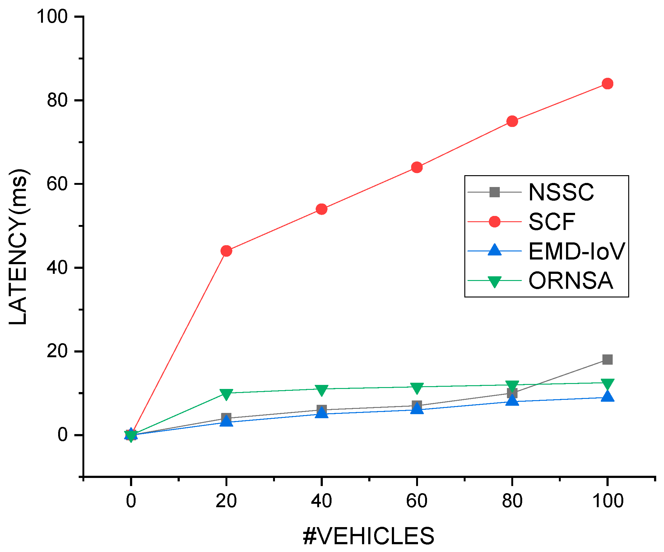
To evaluate the performance of the EMD-IoV approach, we have used Simulator for Urban MObility (SUMO) [35] to generate vehicles’ mobility traces in an urban environment, and both Vehicular Network Simulation Framework (Veins) [36] and SimuLTE [37] framework, which are developed under network simulator OMNET [38], for V2V and V2I communications.
We have simulated our EMD-IoV approach in an urban environment in Manhattan of 10 × 10 km2 covered by 9 eNodeB. We performed our simulation during the 800s and under a vehicle density of 100 vehicles equipped with both DSRC and LTE interfaces. In addition, vehicles broadcast emergency and no-emergency messages each 1s. The main parameters of our simulation are shown in Table 4.
Moreover, we have compared our EMD-IoV approach with three data dissemination approaches: SCF for store–carry–forward scheme [20], NSSC (novel segment-based safety message broadcasting in cluster-based vehicular sensor network) [24], and ORNSA (Optimal Relay Node Selection Algorithm) [26]. Through the experimental study, we aim to evaluate the efficiency of EMD-IoV in terms of reducing the latency transmission and communication collisions, in addition to optimizing the vehicles’ data throughput as well as packet delivery ratio. Therefore, we consider four main metrics in our evaluation: (4.2) Latency to transmit emergency messages, (4.3) average number of communication collisions, (4.4) Packet Delivery Ration (PDR) and (4.5) vehicles’ data throughput.

4.2. Latency

Latency reflects the delay transmission of packets from a source vehicle to a destination vehicle. This metric is very important in the case of emergency message sending. In our EMD-IoV, we have defined the latency as follows:
L a t = P s T r
where Ps: the size of the packet and Tr: the transmission rate (packet/ms).
Figure 14 shows the latency of EMD-IoV as compared to NSSC, SCF, and ORSNA schemes, while varying vehicle density. As we observe, our scheme minimized the latency transmission even when we increased vehicle density, as compared to the other schemes. This is mainly due to our clustering scheme that allows selection of the best routing route, and reduces the number of forwarder vehicles before reaching the destination node. However, the SCF scheme is based on a store and forward principle. The latter enables vehicles to store data in their memories. Once a new vehicle is in the vicinity, the stored data will be sent to this new vehicle. This causes an increase in the latency transmission, especially in sparse density conditions, compared to the other schemes. Similarly, even the ORSNA determines the optimal relay node with two interactions, reducing retransmission due to collision. This causes an increase in the latency transmission. Similarly, even the NSSC and ORNSA are based on clustering schemes, and the authors have used optimization algorithms such as chaotic crow Search to elect the CHs, which may introduce more computing complexity and hence also increase latency delays. Therefore, the increasing latency of SCF, NSSC, and ORNSA is mainly due to the lack of optimal path in broadcasting safety messages.

4.3. Average Number of Collisions

This metric measures the average number of produced collisions during data dissemination. We calculated using the following formula:
A v e r a g e   N u m b e r   o f   C o l l i s i o n s = C p T p
where Cp: the number of collision packets and Tp: the total number of transmitted packets.
Figure 15 depicts the average packets collision of our EMD-IoV in addition to the SCF and NSSC schemes. Fist we see that both our scheme and the NSSC scheme outperform the SCF scheme. Unlike EMD-IoV, ORNSA, and NSSC schemes, as explained before, the SCF scheme is based on a store and forward principle which enables all vehicles in the networks to participate in data dissemination. Thus, this increases the probability of generating collision problems. However, EMD-IoV and NSSC are clustering schemes where only specific nodes are in charge of forwarding emergency messages. Moreover, our EMD-IoV scheme minimizes the number of collisions compared to the NSSC scheme. In fact, our scheme exploits both LTE and DSRC interfaces when disseminating packets in inter and intra-regions, while only DSRC interface is used in the NSSC scheme, which may cause more collisions as it is based more on V2V communications.

4.4. Packet Delivery Ratio (PDR)

This reflects the percentage of successfully delivered packets to the total number of sent packets, when disseminating emergency information. We have measured this metric, as follows:
P D R = S d ; v P s ; v
where, S d ; v : the ratio of successfully received packets by destination vehicle and P s ; v : all packets sent by the source vehicle.
Figure 16 compares the PDR metric of the four aforementioned schemes. As we observe, both ORSNA and SCF schemes generate lower PDR values compared to the other schemes. In ORSNA, only one relay node is chosen in each hop, so the data dissemination depends mainly on only one relay node which causes the PDR to decrease, especially if the relay node leaves the network or a collision is produced. As we mentioned before, in SCF all vehicles in the network are in charge of storing and forwarding data packets. This increases the number of collisions and hence reduces the PDR values. In addition, og 16 shows that the NSSC’s PDR is a little high than our EMD-IoV’s PDR. This is mainly due to the fact that NSSC scheme is based on V2V one-hop communications which highly improves the PDR values, as compared to our scheme where both one-hop and multi-hop communications are performed.

4.5. Throughput

This represents the number of transmitted packets per time unit, as expressed as follows:
T h r o u g h p u t = N b T
where, N b : the number of packets transmitted and T: specific time period.
Figure 17 shows the generated vehicles’ throughput in the three schemes, while varying vehicles density. We clearly see that vehicles’ throughput in our EMD-IoV scheme is higher than the other schemes, thanks to our stable clustering architecture that is based on the link stability metric and optimal selection of LCHs and OCHs. Moreover, the SCF scheme has low vehicle throughput since all vehicles participated in data dissemination, which decreases the global throughput of vehicles.
In general, we can conclude that our EMD-IoV scheme achieves a better and more stable performance compared to the other schemes and even when we increase the number of vehicles. We can deduce that our scheme provides an efficient and reliable dissemination strategy for emergency messages, thanks to our stable clustering architecture. This enables minimization of the number of collisions and transmission latency, while optimizing PDR and vehicles’ throughput in the network. Therefore, EMD-IoV enables to us inform road users, in an urban environment, by emergency information in real-time. Moreover, our scheme can also be exploited to disseminate other types of message such as advertisement and traffic efficiency-related information.

5. Conclusions

In this paper, we addressed the issue of how to share emergency information in an Internet of vehicles environment, given, on the one hand, the high mobility of vehicles and dynamic changes in the topology of such networks, and on the other hand the delay-sensitivity of such messages, in order to inform road users in real time. Thus, we designed a new data dissemination scheme in an urban environment. Our scheme exploits both DSRC and LTE interfaces to propagate emergency information in a short- and long-range way, respectively. A new stable clustering architecture is proposed at the top of our scheme to efficiently disseminate emergency messages and select the optimal forwarders at each communication hop.
We conducted simulations on Omnet++ and SUMO simulators. The results show the efficiency of our scheme as compared with existing schemes. Specifically, our scheme highly reduces packets collisions and transmission latency, in addition to improving both vehicles’ throughput and successfully delivered emergency packets.
As future research, we are working to extend our EMD-IoV approach to highway scenarios in addition to securing its main phases. We also plan to compare the performance of our scheme with other data dissemination schemes supporting both urban and highway environments.

Author Contributions

The major contributions of all the authors are summarized as: The major contributions of all the authors are summarized as: conceptualization—N.A.; methodology—B.B., and M.e.A.F.; software—N.A.; validation—A.K. and B.B.; formal analysis—N.A.; investigation—B.B. and A.K.; re-sources—M.e.A.F.; writing, original draft preparation—N.A., A.K., B.B., and M.e.A.F.; writing, review, and editing—N.A. and M.e.A.F.; visualization—N.A.; supervision—A.K.; project administration—A.K. All authors have read and agreed to the published version of the manuscript.

Funding

This research received no external funding.

Data Availability Statement

The data that support the findings of this study are available from the corresponding author upon reasonable request.

Acknowledgments

The authors would like to thank the General Directorate of Scientific Research and Technological Development, Algeria (DGRSDT), for their support and encouragement.

Conflicts of Interest

The authors declare no potential conflict of interests.

References

  1. Storck, C.R.; Duarte-Figueiredo, F. A 5G V2X Ecosystem Providing Internet of Vehicles. Sensors 2019, 19, 550. [Google Scholar] [CrossRef] [PubMed] [Green Version]
  2. Ahn, S.; Choi, J. Internet of Vehicles and Cost-Effective Traffic Signal Control. Sensors 2019, 19, 1275. [Google Scholar] [CrossRef] [Green Version]
  3. Wang, J.; Shao, Y.; Ge, Y.; Yu, R. A Survey of Vehicle to Everything (V2X) Testing. Sensors 2019, 19, 334. [Google Scholar] [CrossRef] [Green Version]
  4. Lagraa, B.B.N.; Lakas, A.; Ghamri-Doudane, Y. RCS-VC: Renting out and consuming services in vehicular clouds based on LTE-A. In Proceedings of the 2015 Global Information Infrastructure and Networking Symposium (GIIS), Guadalajara, Mexico, 28–30 October 2015; pp. 1–6. [Google Scholar]
  5. Azzaoui, N.; Korichi, A.; Brik, B.; Fekair, M.E.A.; Kerrache, C.A. On the Communication Strategies in Heterogeneous Internet of Vehicles. In The Proceedings of the Third International Conference on Smart City Applications; Springer: Cham, The Netherland, 2019; pp. 783–795. [Google Scholar]
  6. Do, D.-T.; Van Nguyen, M.-S.; Le, A.-T.; Rabie, K.M.; Zhang, J. Joint Full-Duplex and Roadside Unit Selection for NOMA-Enabled V2X Communications: Ergodic Rate Performance. IEEE Access 2020, 8, 140348–140360. [Google Scholar] [CrossRef]
  7. Do, D.T.; Le, T.A.; Nguyen, T.N.; Li, X.; Rabie, K.M. Joint Impacts of Imperfect CSI and Imperfect SIC in Cognitive Ra-dio-Assisted NOMA-V2X Communications. IEEE Access 2020, 8, 128629–128645. [Google Scholar] [CrossRef]
  8. Ang, L.-M.; Seng, K.P.; Ijemaru, G.K.; Zungeru, A.M. Deployment of IoV for Smart Cities: Applications, Architecture, and Challenges. IEEE Access 2019, 7, 6473–6492. [Google Scholar] [CrossRef]
  9. Shen, X.; Li, J.; Chen, L.; Chen, J.; He, S. Heterogeneous LTE/DSRC Approach to Support Real-time Vehicular Communications. In Proceedings of the 2018 10th International Conference on Advanced Infocomm Technology (ICAIT), Stockholm, Sweden, 12–15 August 2018; pp. 122–127. [Google Scholar]
  10. Azzaoui, N.; Korichi, A.; Brik, B.; Fekair, M.E.A.; Kerrache, C.A. Wireless communication in internet of vehicles networks: DSRC-based Vs cellular-based. In Proceedings of the 4th International Conference on Smart City Applications—SCA’ 19, Casablanca, Morocco, October 2019; ACM: New York, NY, USA, 2019; p. 23. [Google Scholar]
  11. Tamani, N.; Brik, B.; Lagraa, N.; Ghamri-Doudane, Y. Vehicular Cloud Service Provider Selection: A Flexible Approach. In Proceedings of the GLOBECOM 2017—2017 IEEE Global Communications Conference, Singapore, 4–8 December 2017; pp. 1–6. [Google Scholar]
  12. Road Accidents in the United States—Statistics & Facts. Available online: https://www.statista.com/topics/3708/road-accidents-in-the-us/ (accessed on 15 February 2021).
  13. Congestion Costs U.S. Cities Billions Every Year. Available online: https://www.statista.com/chart/21085/annual-economic-losses-from-traffic-congestion/ (accessed on 15 February 2021).
  14. Ali, M.; Malik, A.W.; Rahman, A.U.; Iqbal, S.; Hamayun, M.M. Position-based emergency message dissemination for Internet of vehicles. Int. J. Distrib. Sens. Netw. 2019, 15, 1550147719861585. [Google Scholar] [CrossRef] [Green Version]
  15. Tian, D.; Liu, C.; Duan, X.; Sheng, Z.; Ni, Q.; Chen, M.; Leung, V.C.M. A Distributed Position-Based Protocol for Emergency Messages Broadcasting in Vehicular Ad Hoc Networks. IEEE Internet Things J. 2018, 5, 1218–1227. [Google Scholar] [CrossRef]
  16. Do, D.-T.; Van Nguyen, M.-S.; Voznak, M.; Kwasinski, A.; de Souza, J.N. Performance Analysis of Clustering Car-Following V2X System with Wireless Power Transfer and Massive Connections. IEEE Internet Things J. 2021, 1. [Google Scholar] [CrossRef]
  17. Liu, L.; Chen, C.; Qiu, T.; Zhang, M.; Li, S.; Zhou, B. A data dissemination scheme based on clustering and probabilistic broadcasting in VANETs. Veh. Commun. 2018, 13, 78–88. [Google Scholar] [CrossRef]
  18. Brik, B.; Lagraa, N.; Cherroun, H.; Lakas, A. Token-based Clustered Data Gathering Protocol (TCDGP) in vehicular networks. In Proceedings of the 2013 9th International Wireless Communications and Mobile Computing Conference (IWCMC), Sardinia, Italy, 1–5 July 2013; pp. 1070–1074. [Google Scholar]
  19. Brik, B.; Lagraa, N.; Lakas, A.; Cherroun, H.; Cheddad, A. ECDGP: Extended cluster-Based data gathering protocol for vehicular networks. Wirel. Commun. Mob. Comput. 2015, 16, 1238–1255. [Google Scholar] [CrossRef] [Green Version]
  20. Nguyen, T.D.; Le, T.-V.; Pham, H.-A. Novel store–carry–forward scheme for message dissemination in vehicular ad-hoc networks. ICT Express 2017, 3, 193–198. [Google Scholar] [CrossRef]
  21. Latif, S.; Mahfooz, S.; Ahmad, N.; Jan, B.; Farman, H.; Khan, M.; Han, K. Industrial Internet of Things Based Efficient and Reliable Data Dissemination Solution for Vehicular Ad Hoc Networks. Wirel. Commun. Mob. Comput. 2018, 2018, 1–16. [Google Scholar] [CrossRef] [Green Version]
  22. Alsuhli, G.H.; Khattab, A.; Fahmy, Y.A. Double-Head Clustering for Resilient VANETs. Wirel. Commun. Mob. Comput. 2019, 2019, 1–17. [Google Scholar] [CrossRef]
  23. Tambawal, A.B.; Noor, R.M.; Salleh, R.; Chembe, C.; Oche, M. Enhanced weight-based clustering algorithm to provide reliable delivery for VANET safety applications. PLoS ONE 2019, 14, e0214664. [Google Scholar] [CrossRef]
  24. Alkhalifa, I.S.; Almogren, A.S. NSSC: Novel Segment Based Safety Message Broadcasting in Cluster-Based Vehicular Sensor Network. IEEE Access 2020, 8, 34299–34312. [Google Scholar] [CrossRef]
  25. Aissa, M.; Bouhdid, B.; Ben Mnaouer, A.; Belghith, A.; Alahmadi, S. SOFCluster: Safety-oriented, fuzzy logic-based clustering scheme for vehicular ad hoc networks. Trans. Emerg. Telecommun. Technol. 2020, 20, e3951. [Google Scholar] [CrossRef]
  26. Feng, D.; Yajie, M.; Fengxing, Z.; Xiaomao, W.; Kai, H. A Safety Message Broadcast Strategy in Hybrid Vehicular Network Environment. Comput. J. 2017, 61, 789–797. [Google Scholar] [CrossRef]
  27. Ebadinezhad, S.; Dereboylu, Z.; Ever, E. Clustering-Based Modified Ant Colony Optimizer for Internet of Vehicles (CACOIOV). Sustainability 2019, 11, 2624. [Google Scholar] [CrossRef] [Green Version]
  28. Guangjin, H.; Guang, Y.; Yubao, C.; ChaoFeng, M. Design and Implementation of Traffic Incident Acquisition and Reporting Device Based on LTE Communication. J. Phys. 2020, 1486, 022023. [Google Scholar] [CrossRef]
  29. Aadil, F.; Ahsan, W.; Rehman, Z.U.; Shah, P.A.; Rho, S.; Mehmood, I. Clustering algorithm for internet of vehicles (IoV) based on dragonfly optimizer (CAVDO). J. Supercomput. 2018, 74, 4542–4567. [Google Scholar] [CrossRef]
  30. Lin, F.; Liu, Y. An integration of WAVE and LTE wireless transmission in vehicle networks for safety and non-safety messages dissemination. In Proceedings of the 2017 3rd IEEE International Conference on Computer and Communications (ICCC), Chengdu China, 13–16 December 2017; pp. 315–320. [Google Scholar]
  31. Wu, C.; Yoshinaga, T.; Chen, X.; Zhang, L.; Ji, Y. Cluster-Based Content Distribution Integrating LTE and IEEE 802.11p with Fuzzy Logic and Q-Learning. IEEE Comput. Intell. Mag. 2018, 13, 41–50. [Google Scholar] [CrossRef]
  32. Tseng, H.-W.; Wu, R.-Y.; Lo, C.-W. A stable clustering algorithm using the traffic regularity of buses in urban VANET scenarios. Wirel. Netw. 2019, 26, 2665–2679. [Google Scholar] [CrossRef]
  33. Senouci, O.; Harous, S.; Aliouat, Z. A New Heuristic Clustering Algorithm Based on RSU for Internet of Vehicles. Arab. J. Sci. Eng. 2019, 44, 9735–9753. [Google Scholar] [CrossRef]
  34. Ahmad, A.; Din, S.; Paul, A.; Jeon, G.; Aloqaily, M.; Ahmad, M. Real-Time Route Planning and Data Dissemination for Urban Scenarios Using the Internet of Things. IEEE Wirel. Commun. 2019, 26, 50–55. [Google Scholar] [CrossRef]
  35. Simulation of Urban Mobility. SUMO Official Web Site. Available online: https://www.eclipse.org/sumo/ (accessed on 24 August 2020).
  36. VEINS. The Open Source Vehicular Network Simulation Framework. Available online: https://veins.car2x.org/ (accessed on 25 August 2020).
  37. LTE. Use Plane Simulation Model for INET & OMNET++. Available online: http://veins-lte.car2x.org/ (accessed on 25 August 2020).
  38. OMNeT++ Discrete Event Simulator. Available online: https://omnetpp.org/ (accessed on 20 August 2020).
Figure 1. V2X Communications in the Internet of Vehicles.
Electronics 10 00979 g001
Figure 2. Our EMD-IoV approach in urban IoV environment.
Electronics 10 00979 g002
Figure 3. Cluster states graph.
Electronics 10 00979 g003
Figure 4. Hello Message format.
Electronics 10 00979 g004
Figure 5. Election Message format.
Electronics 10 00979 g005
Figure 6. ACK Message format.
Electronics 10 00979 g006
Figure 7. Request_LCH message format.
Electronics 10 00979 g007
Figure 8. Candidat_LCH message format.
Electronics 10 00979 g008
Figure 9. Select_LCH message format.
Electronics 10 00979 g009
Figure 10. Gateway_Selection message format.
Electronics 10 00979 g010
Figure 11. REQUEST_ROUTE Message Format.
Electronics 10 00979 g011
Figure 12. UPDATE_Geo-Zoning message format.
Electronics 10 00979 g012
Figure 13. Real_time Data (emergency message) format.
Electronics 10 00979 g013
Figure 14. Performance evaluation in terms of transmission latency.
Electronics 10 00979 g014
Figure 15. Performance evaluation in terms of packets collision.
Electronics 10 00979 g015
Figure 16. Performance evaluation in terms of packets delivery ratio.
Electronics 10 00979 g016
Figure 17. Performance evaluation in terms of vehicles’ data throughput.
Electronics 10 00979 g017
Table 1. Summary of acronyms.
AcronymDefinition
IoTInternet of Things
VANETVehicular Ad-hoc Network
ITSIntelligent Transport System
VSNVehicular Sensor Network
IoVInternet of Vehicle
OBUOn-Board Unit
V2VVehicle-to-Vehicle
V2IVehicle to Infrastructure
V2RVehicle-to-Road
V2Pvehicle to Pedestrian
V2HVehicle to Home
V2GVehicle to Grid
V2XVehicle to Everything
EMEmergency Message
UVUn-clustered-Vehicles
FVForwarder Vehicle
OCOrdinary Cluster
CMCluster Member
OCMOrdinary Cluster Member
OCHOrdinary Cluster Head
MPRMulti Point Relay
MPROCMulti Point Relay of Ordinary Cluster
LCLeader Cluster
LCHLeader Cluster Head
GCGateway Cluster
GCHGateway Cluster Head
CCCluster Connector
RSURoad Side Unit
DSRCDedicated Short Range Communications
LTELong Term Evolution
eNodeBevolved Node-B
LRLink Reliability
QoSQuality of Service
VRVehicle Reliability
LQELink Quality Estimation
RTRouting Table
RERegion
Table 2. Comparison between data dissemination approaches.
Ref.Proposed SolutionStrategyCommunication Model/Using TechnologySelection CH MetricsEnvironmentSimulation Scenarios/Tools
Alsuhli, et al. (2019) [22]Double-head clustering Algorithm (DHC)ClusteringV2V
(DSRC)
speed, position, direction, communication link quality, popularity
link expiration time
Vaneturban and highway
(NS3)
Alkhalifa, et al. (2020) [24]Novel Segment Based Safety Message Broadcasting in Cluster (NSSC)clustering,
broadcasting,
forwarding
V2V
(IEEE 802.11p)
optimal CH: using CCS algorithm (Mobility, Connectivity)VSNurban
(Omnet)
Senouci et al. (2019) [33]Heuristic clustering algorithm based on RSU (HCAR)clustering,
broadcasting
V2V/V2I
(IEEE 802.11p)
(LTE)
velocity, degree,
transmission range
IoVhighway
(NS2)
Guangjin et al. (2020) [28]Traffic incident acquisition and reporting deviceBroadcastingV2I/I2V
(4G/LTE-V2X)
--------------IoVurban
Latif et al., 2018 [21]Data dissemination protocol for VANETs (DDP4V)carry forward
mechanism
V2V
(802.11p)
--------------Vanethighway and urban
(Omnet)
Nguyen et al. (2017) [20]Store-carry-forward scheme for message dissemination (SCF)store carry forwardV2V
(802.11p)
--------------Vanethighway
(Omnet)
Tseng et al. (2019) [32]Clustering algorithm using the traffic regularity of buses (CATRB)ClusteringV2V/V2I
(IEEE 802.11p) (LTE)
velocity, position,
and direction
(CH in the center
of the cluster)
Vaneturban
Lin et al. (2017) [30]Integration of WAVE and LTE in Vehicle Networks for Messages Dissemination
(IWL-VNMD)
ForwardingV2V/V2I
(IEEE 802.11p) (LTE)
--------------Vaneturban
(NS3)
Ebadinezhad et al. (2019) [27]Clustering algorithm based on modified ant colony optimizer (CACOIOV)metaheuristic clusteringV2X
(5G)
node speed, distance, direction, local traffic density using DA-TRLD algorithmIoVhighway
(NS2)
Bello et al. (2019) [23]enhanced weight-based clustering algorithm (EWCA)ClusteringV2V
(DSRC)
highest weight value (speed, distance, and connectivity level)Vanethighway
(NS3)
Aissa et al. (2020) [25]novel cluster-head (CH) selection schemeClusteringV2V/V2I
(DSRC)
intervehicle distanceVaneturban and highway
(Omnet)
Feng et al. (2018) [26]safety message broadcast strategy (SMBS)broadcasting,
forwarding
V2V/V2I
(4G LTE)
optimal forwarder (link stability, signal strength, channel quality)Vanethighway
(NS2)
Wu et al. (2018) [31]cluster-based protocol integrating LTE with IEEE 802.11pClusteringV2V
(IEEE 802.11p) (LTE)
(velocity, distribution, channel condition) using fuzzy logic based algorithmVanethighway
(NS2)
Adil et al. (2018) [29]clustering algorithm based on dragonfly optimization (CAVDO)metaheuristic clusteringV2X
(5G)
distance, speed,
direction
IoVhighway
(Matlab)
Awais Ahmad et al. (2019) [35]real-time data dissemination schemeForwardingV2R/V2S/V2X--------------Vaneturban
(NS3)
Table 3. Node state transition.
CMOCHMPRCCLCHGCH
UVjoin a clusterelection processjoin a cluster as gateway CM///
CM/best VRlocation changelocation change//
OCHbecome CM/gateway role with neighbor cluster/Best LQE/
selection_LCH
gateway role with neighbor
region
MPRlocation changebecome an OCH/gateway role with neighbor region//
CClocation change/////
LCH/location change///geographical location change
GCH/leaving cluster////
Table 4. Simulation Parameters.
ParameterValue
Omnet version4.6
Sumo version0.25.0
Veins version4.4
Simulation Area10 km × 10 km
Simulation time800 s
Number of vehicles100
Vehicle velocity50 km/h
Mobility model Manhatan
Number of Antenna9
Communication standard IEEE 802.11p, LTE
Antenna type Omni-directional
Packet size512 bytes
Packets interval 1 s
Transmission range 250 m
Publisher’s Note: MDPI stays neutral with regard to jurisdictional claims in published maps and institutional affiliations.

