1. Introduction
In the last decade, growing interest can be found in the domain of stretchable electronic systems. This field is so attractive to researchers and market players not only because of the unique opportunities to use a multitude of materials such as paper, textile, or plastics, but also because it allows for the creation of devices sporting excellent comfort, compatibility, fit, and deformation [
1,
2]. Even though this research area can still be considered in its infancy, work has been presented where sensing elements, new production ideas, and design, have been seamlessly brought together to build wearables that do not alienate their user and blend easily into their daily clothing [
3,
4,
5,
6].
As such, devices require materials that need to exceed the mechanical properties of thin films, commonly found in printed circuit board design, via an aspiring new field using the integration of textiles, in particular, conductive threads that enable the creation of the so-called e-textile domain [
7,
8].
There should be no misconception that conductive threads are the only solution to creating e-textiles, although there are alternatives such as the utilization of metallic interconnects through lithographic processes, screen printing [
9], micro dispensing [
10], or even inkjet printing [
11,
12,
13,
14]. However, such approaches, combined with the extreme and uneven roughness of woven materials, wicking phenomena, and abrasion due to washing chemicals, even though good at conserving materials, may not be the most suitable candidates for creating long-lasting e-textiles.
Alternatively, if the added functionality of the textile or garment is provided by its very own threads [
15], it is overall expected to have a much longer useable lifetime. This idea of creating conductive fibers that can create threads is already well researched. Silver has been used to coat nylon and cotton threads at varying densities in [
16], as well as polyester and polyester/rubber compounds in [
17]. In Reference [
18], PEDOT: PSS-coated conductive fibers were fabricated and found to be about 10 times less conductive than Ag coated equivalents. Lastly, in [
19] the researchers are coating with polypropylene, commercially available yarns to avoid short-circuiting under many occasions, such as submersion in water. They wrap polypropylene fibers around the Ag-coated polyamide yarns through friction spinning, then subsequently melting the product in an oven for binding purposes.
So far, researchers have primarily focused on investigating the effects of adverse conditions on the fabrics, such as the effects of different types and classes of stitching [
20], consecutive abrasion [
21] or repeated washing cycles [
15,
21], as well as the effects of chemicals used as detergents or ironing agents [
22]. However, very little light has been shed on how the conductive thread itself can handle power fed through it, and how that can affect it [
23,
24]. In addition, there is a lack of information in open literature or in catalogs of threads producers about the maximum electrical current or voltage that can be applied on the conductive thread, which are very valuable data from a practical point of view. Therefore, the scope of this work is to investigate the ability of commercially available threads to handle and sustain electrical loads, and to what extent they can act as a viable and stable conductor choice for e-textiles.
2. Materials and Methods
For this work, four different commercially available threads were studied. HC 12 and HC 40 were supplied by MADEIRA Garnfabrik [
25,
26], and both comprised of 100% Polyamide/Silver plated yarn. HC 12 has a thread count of 235 × 2 dtex without silver coating and 610 dtex ± 15 dtex with silver coating. HC 40 has a thread count of 117 × 2 dtex without silver coating and 290 dtex ± 6 dtex with silver coating and belonging to the Shieldex
® series manufactured by Statex Produktions- und Vertriebs GmbH. The two remaining threads (Silver-Tech 50 and Silver-Tech 120) were supplied by AMANN Group [
27] and belong to their Silver-Tech series.
Table 1 below summarizes the electrical properties of all four threads. The threads acquired represent the majority of the manufacturer’s catalogs, and these specific two manufacturers cover most of the market in Serbia.
All threads are made of either polyamide, or polyamide-polyester compound, and are subsequently silver plated. As this material is among the most used man-made fibers, these threads are made by melt-spinning. To make each filament, or simply put, a single strand in the thread, it is molten, then pressed through spin plates tuning the dosage, successively cooled down, and extended. That leads to the crystalline areas of the polymer sliding off and aligning in the direction of the pulling. This creates a more elastic thread [
28,
29]. The plating of the threads is preferably done with silver, not only because it exhibits antimicrobial properties and chemical resistance, but also because of its high electrical conductivity values. The plating does not yield a uniform silver foil, but instead a quite rough cover, varying in thickness from 50 nm–200 nm [
30,
31].
Fifty-one samples of each thread were precision-cut to a length of 1 centimeter, all of which coming from the same yarn of thread, to avoid any potential production imperfections among different lots of threads. One sample of each thread was kept aside for study as a healthy specimen and the rest were to be destroyed in the process of experimentation. The reason for selecting samples of this length is because longer samples will bend under the force of gravity, as they were examined as free-standing structures, and they were more susceptible to collapse at the bent area. Moreover, smaller samples have very small resistance values and can therefore be affected by contact/instrument resistance.
2.1. Governing Theoretical Principles
In terms of electrical characterization, the threads had to inevitably form part of a circuit. Even though in practical applications, they are intended to act as wires or transmission lines given their high values of resistivity, they were examined as resistors. In that sense, a capable circuit enabling the measurement of their actual resistance can be a simple voltage divider, consisting of a resistor of a known value and a piece of thread connected in series between two points of difference in potential.
Acting as resistors, in the case of Direct Current (DC) or low-frequency Alternating Current (AC), the primary phenomenon in which the threads are a major factor is Joule heating (also termed Ohmic heating or resistive heating). In consumer electronics, DC circuits are more common, and we will focus on DC characterization in this paper. According to the Joule-Lenz law (1), the power of heating generated by an electrical conductor, P(W), is proportional to the product of its resistance R(Ω), and the square of the DC current I(A), and the whole material is affected.
Therefore, if the current intensity through the threads is high enough, a temperature rise will not only be present but also severe enough to, in principle, melt the polyamide/polyamide-polyester core of the thread fibers and destroy them.
However, that can also create a two-fold problem in the characterization process. On one hand, the threads have a very high surface area compared to their overall size, so they can very effectively dissipate the generated heat to the air surrounding them. That can virtually lead to them sustaining a higher amperage than the case of being woven into a fabric.
On the other hand, that free surface area can lead to structural damages in the material, even before the temperature increase can be observed, as the thread could start exhibiting a temperature gradient between its core and outer surfaces. That is why extra steps need to be taken to mitigate these effects to the extent possible, to achieve the most accurate characterization possible.
2.2. Design of Experiment
Given the above points to be considered, 51 samples of 1 cm in length were taken from each of the four threads. A healthy sample at random was selected to be examined under Scanning Electron Microscopy (SEM), to cross-reference its condition with that of the electrically burned thread after the end of the experiment.
The experiment was split into two parts. For the first part, 25 samples of each thread were in succession subjected to a constantly increasing voltage, and consequently amperage, until their breaking point, as part of a voltage divider circuit. Voltage was being increased at a rate of 0.1 V/sec. For the second part, again twenty-five samples of each thread were placed to form part of a voltage divider circuit in succession, only this time the increase in voltage was stepped up and sustained, for an interval of 60 s at a time until their breaking point (
Figure 1). These steps in terms of voltage increase were not the same among the four different fabrics, but the increase rate and time spent on each step were maintained for all the samples of the same group. This differentiation was applied to provide an insight on normal, relatively stable, operating conditions in the former case, and the thread behavior in fast-increasing voltage conditions, such as circuit faults in the latter case. Moreover, this can be very useful if the thread is a part of a system for continuous energy delivery (low-power antennas for example) or other demanding wearable application, such as battery charging, etc.
The rationale for choosing the circuit shown in
Figure 1, even though seemingly simple, is because it presents a reliable approach to determining the behavior of conductive threads in terms of electrical resistance and power. This is because it perfectly reflects the conditions in which the threads are going to be used. That can be further explained by the fact that in many applications of flexible and stretchable electronics, the voltage drops on electrical threads due to their electrical resistance and change of their electrical resistance are big concerns. The electrical response of the circuit can be affected if the used threads significantly change their characteristics due to the change of electrical current flowing through them. More importantly, if the exact maximum electrical rating in terms of power and resistance are not known, there is a huge possibility of malfunction of the device due to the wrong design that does not meet real-life applications. Additionally, there are a plethora of electronic circuits where the voltage divider is inevitable as an input part in buffers or microcontrollers-based devices.
The room in which the experiment was carried out was not regulated atmospherically, but a special enclosure to the testing part was 3D printed. This allowed for convective heat dissipation to unperturbed ambient air surrounding the thread, without any suddenly forced air streams, to normalize the environment of the experiment while maintaining real conditions.
Furthermore, an additional holding structure was designed, and 3D printed, as the threads were becoming too hot for a probe-type lead to hold them without melting, and standard crocodile clips had to be used.
Figure 2 below showcases this structure, without the enclosure.
In addition to that, the electrical performance of the thread was simulated using COMSOL Multiphysics ver. 5.5, as an extra means of characterization of the threads. Burned (failed) threads were then subsequently studied again under SEM (TM3030, Hitachi, Japan).
2.3. Simulation Setup
A model of the 1-centimeter-long thread, for each type of thread, was created in 3D using Autocad by Autodesk, considering the number of threads in each filament, the number of twists, their optical diameters, and other various properties either derived through experimentation or supplied by the thread manufacturers. The thread model was then imported into COMSOL Multiphysics as the main geometry, and materials were added to it, to enable the physics study. Polyamide 6.6 was added to the individual fibers and given the fact that the Silver plating has a negligible thickness compared to the thickness of the polymer core, it was added as a boundary condition. This addition allowed for the creation of conductive surfaces only on the outside part of the individual strands.
As some of the threads have a part that is not conductive, appropriate care was taken to exclude these boundaries when applying the silver and selecting the physics interfaces. Given the very high complexity of the model, i.e., individual silver-plated fibers spun together in groups, and more than one of these groups spun together into the thread, the model was examined cross-sectionally in a 2D geometry.
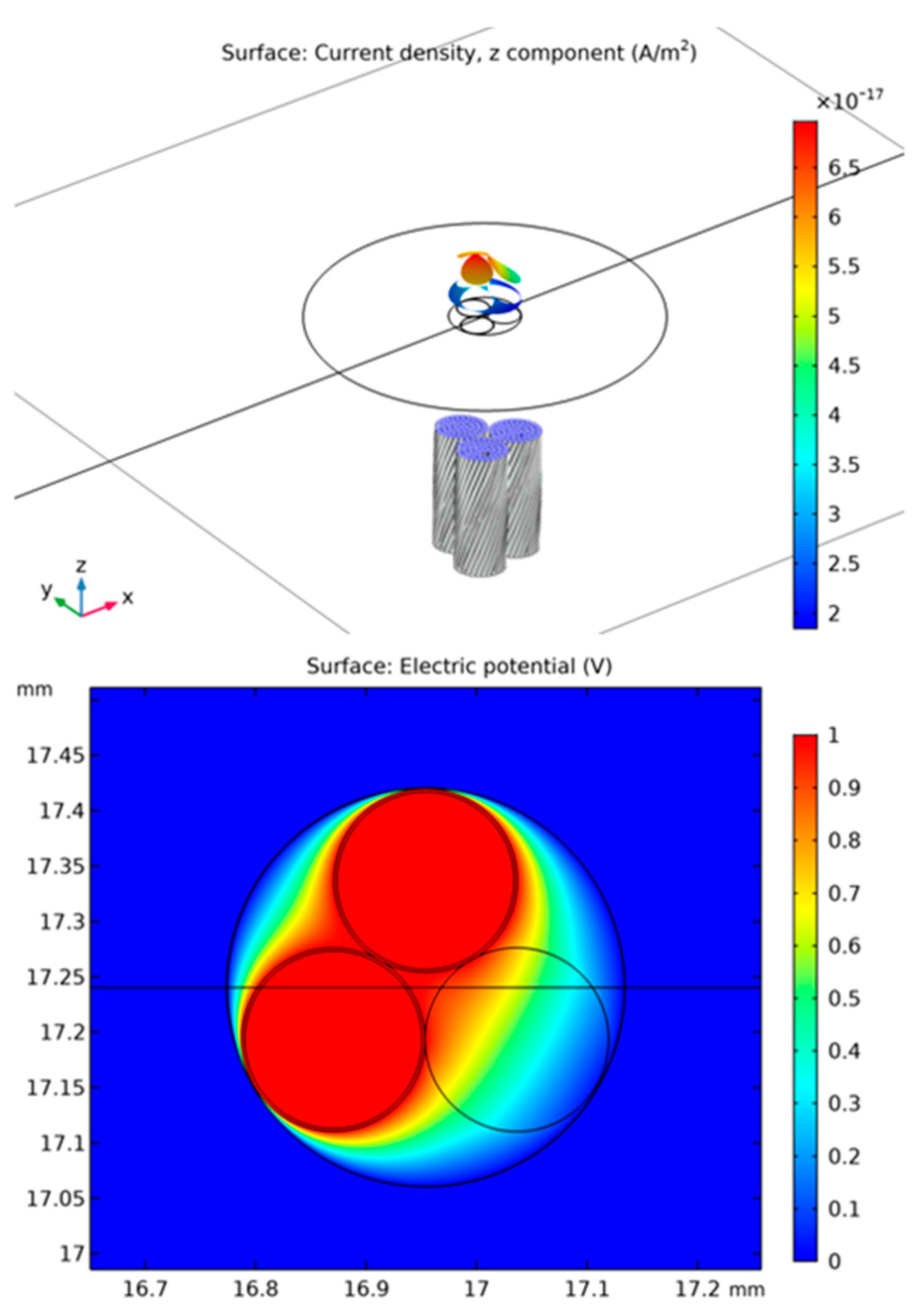
Figure 3 showcases the 3D model used to create the out-of-plane current density graph on the top, and a simplified 2D electric potential graph on the bottom part. The ground and positive voltage were applied along the z-axis, to the entire face of the model in 3D. However, one of the three groups of fibers was not coated in silver, and as a result, the out-of-plane current density was higher in the two coated groups. Someone would expect the third group to show as equipotential to ground; however, as polypropylene is not a perfect insulator, and the simulation mesh is finite, in principle, the software shows the fading of the two other groups. This could also be seen in the simplified 2D cross-section of the same model, where the electric potential appeared to be radiating halfway through the bottom right circle, which represented the surface area of the non-coated group.
By applying a varying voltage to the two ends of the model, COMSOL can estimate the resistance of the model, in the same way, the experiment can verify it. In the case of
Figure 3, the excitation voltage was set to 1 V; however, this simulation was run for the entire set of values the experiment was also realized.
To accommodate the difference between the instantaneous voltage increase, and the stepped, continuous approach, two different studies were selected being, stationary which disregards any temporal effects, and frequency-transient, to study the effect of 60 s of time between every consecutive voltage step. The results are shown below in
Table 2.
3. Results
The experimental results of this piece of work were acquired in stages. During the experimentation stage, values for voltage between the ends of the thread and current through the circuit were being registered to allow for power calculation at every step. Additionally, visual cues were taken, such as the sudden contraction of the threads before their failure. Averaging and other statistical processing was performed in GraphPad Prism at a later stage. Lastly, the samples used in the experimentation stage were examined under SEM later, but also healthy ones were observed for cross-referencing purposes.
3.1. Thread Electrical Performance
Initially, the primary point to be established was to what extent the nominal values for resistance given by the manufacturers of the threads (
Table 1) can be verified. The reason for this was that none of the threads was supplied with a set value of resistance and a tolerance percentage, as standard resistor components or cables do, but instead, they came with a wide range of values.
The first step of this work was to calculate the individual resistance of each sample, and qualitatively extract the average value per thread type. This was made possible using the VI method, i.e., by reading the voltage across and current intensity through the sample and using Ohm’s law to calculate the resistance.
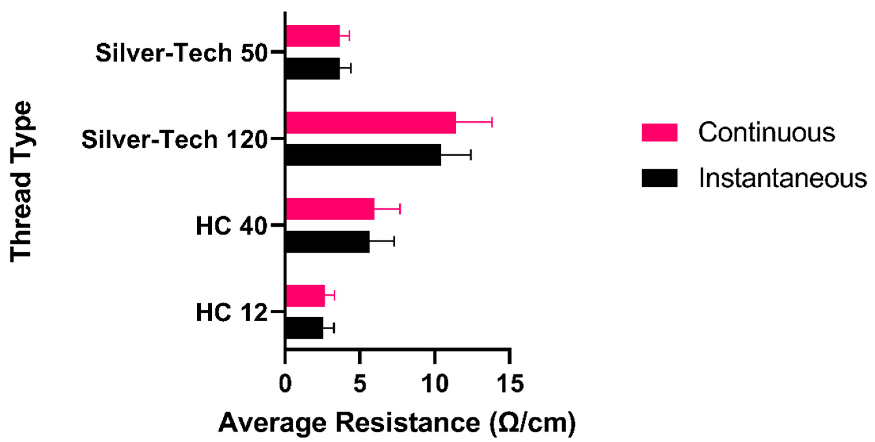
Figure 4 demonstrates the average resistance of each of the groups of five samples, as well as the standard deviation of each group. It can be easily seen that except for the Silver-Tech 120, all other threads had a relatively stable resistance among different samples, which is to be expected, assuming the material is uniform.
Additionally, one can see that in all four cases, in the instantaneous voltage increase mode, the average resistance values are somewhat lower than in the case of the incremental voltage ramp-up. This can be explained by the fact that in the second case, the threads had more time to get hot progressively. Given the fact that the resistance of every material is temperature-dependent and this can be approximated into a linear relationship, it can be deduced that all the threads had a positive temperature coefficient (PTC). This PTC effect can be tuned by controlling the concentration of silver embedded around the polyamide core of the threads.
Table 3 below summarizes the resistance values per thread type, as calculated through the various experimentation steps, and using the setup shown in
Figure 1.
Another interesting finding is the performance differences among the four threads examined, and most notably, between these of the same families.
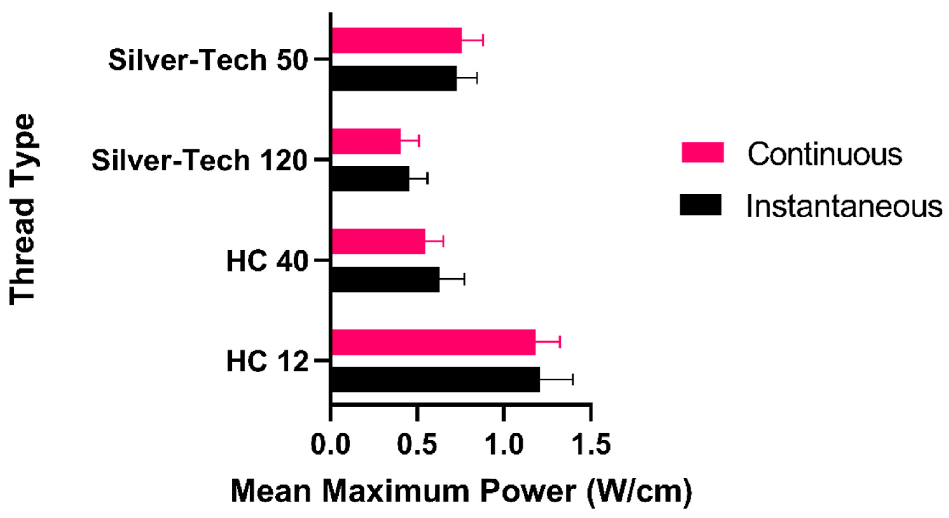
Figure 5 presents the performance of all the threads for their mean maximum attainable power before failing.
It was evident that in general, all threads seemed able to tolerate higher instantaneous power than continuous, a finding that was in line with the effects of Joule heating. These effects eventually cause such a high-temperature rise in the material that will make it fail with time. Even though HC 12 and Silver-Tech 50 seemed to sustain more power in the continuous setting, that was not the case, as their standard deviation margins significantly increased compared to the instantaneous setting, and such a claim cannot be generalized.
Another notable finding was that the Silver-Tech 120 was the most volatile thread of all, with individual samples demonstrating differences in maximum power sustained as big as 170 mW. Thus, one should proceed with extra caution when planning sensitive electronic circuits relying on that thread.
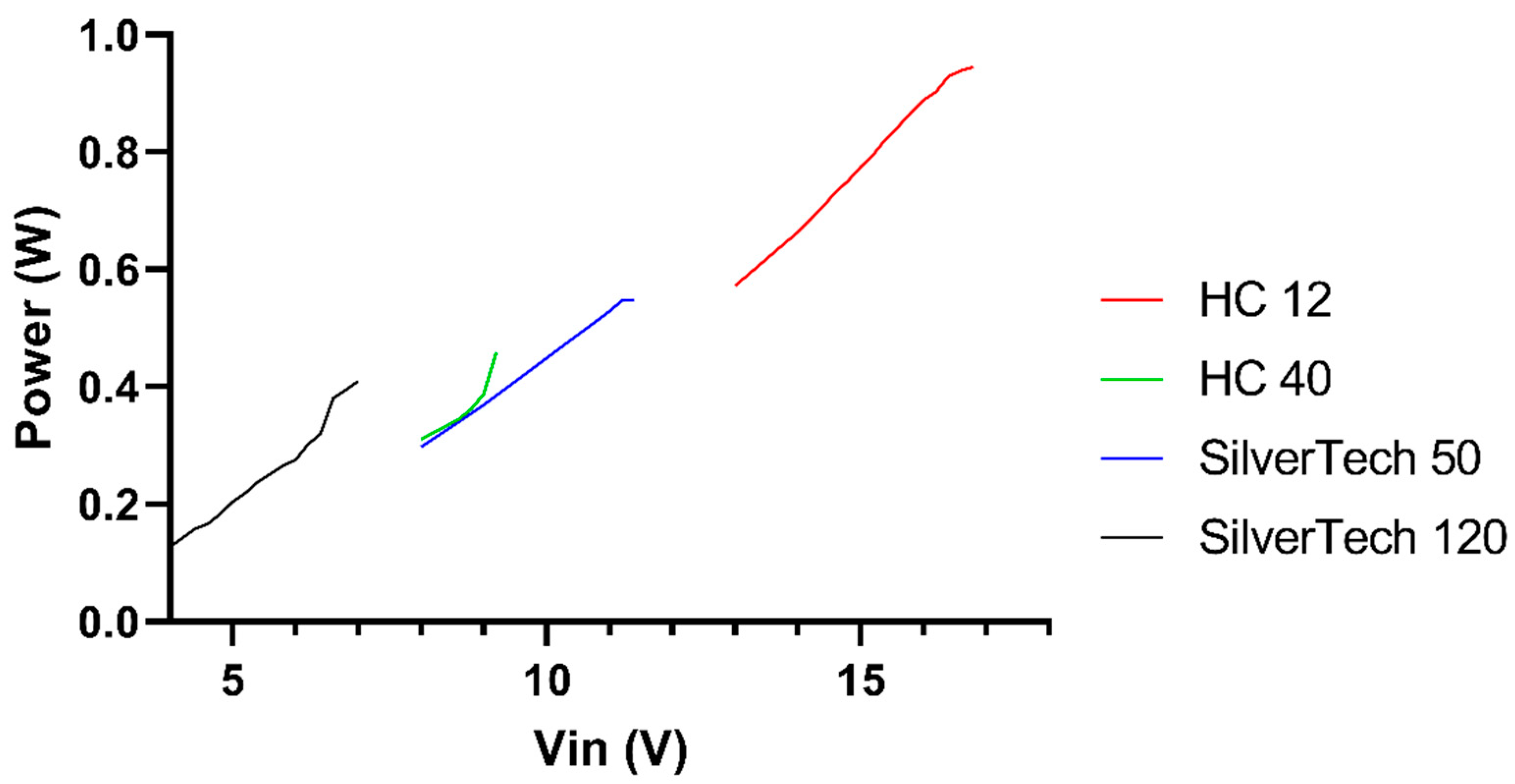
Since in the experiment design, four different threads were put in a voltage divider circuit, it is useful to study them for the input voltage, from 0 V to their registered breakdown voltage. As shown in
Figure 6, each thread fails at a distinct range, virtually giving the end-user an almost full coverage to the range from 0 V to 17 V. That is recorded with the circuit described in
Figure 1 and can be tweaked accordingly with the rest of the circuit elements. However, it was still an unexpected find, as no matter the difference in power handling capabilities of the threads, with the four studied, a whole voltage spectrum could be uninterruptedly covered. That is a great advantage, as by just sewing a different thread to an unchanged circuit, the voltage and power could be changed. It should be noted that in
Figure 6, except for Silver-Tech 120, only voltages relatively close to the failing point of individual samples have been plotted for clarity.
Lastly, it was good to see that the differences between the mean sustained power in the two modes for each fiber were very small, with Silver-Tech 50 exhibiting the biggest difference of all, at 35.5 mW. This was still less than 10% compared to the individual mean values recorded, 551 mW for instantaneous and 586 mW for continuous operation, respectively.
3.2. Thread Structural Behaviour
Aside from the electrical performance of the threads, by pushing them to their limits, they sustained significant damages to their structure, which were observed visually during the experiment, and then subsequently examined under SEM. The main remark from the visual observation was that all threads presented here were starting to contract along their length axis when they were close to failing.
Table 4 summarizes this behavior. That gave rise to the hypothesis that all the threads failed, not because they reached their absolute limits, but because due to being anchored on both sides to the crocodile clips providing the potential difference, this contraction led to them physically splitting in half.
Such a finding does not invalidate the results of the experimentation, both because the time elapsed between the contraction of the threads and the actual separation was extremely small, and because after sustaining such significant damage, it was obvious that such a thread would not be used again as intended. It is worth mentioning that the contraction observed was permanent, as after removing the applied voltage even before the threads failed, their original length was never restored. Even though that can be attributed to the materials and techniques used in the fabrication of such threads, such research is beyond the scope of this paper.
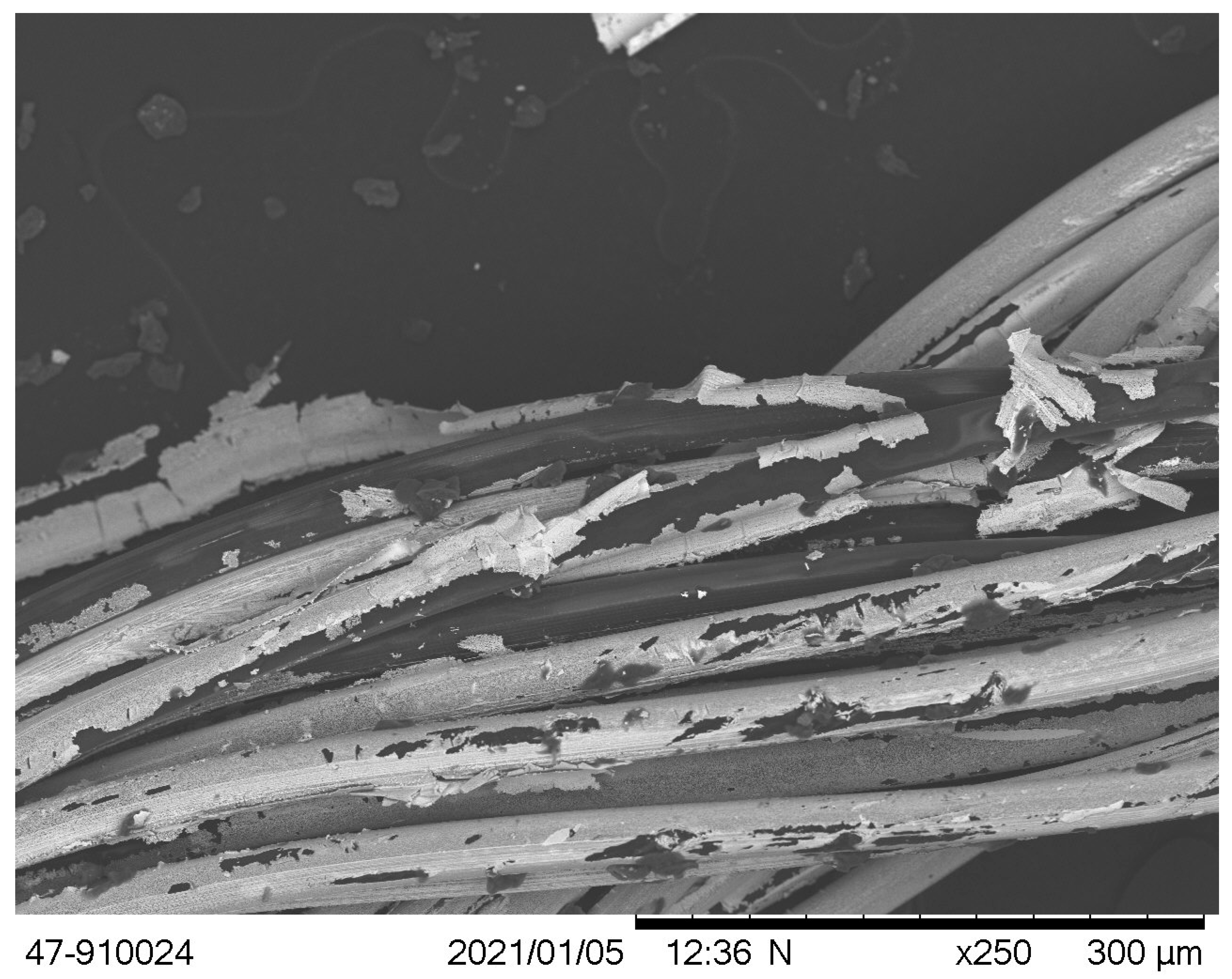
Figure 7 demonstrates a healthy sample of the Silver-Tech 120 thread, which was cut from the same yarn as the samples used in the electrical characterization piece of this work. A striking observation was the existence of an extensive amount of delamination of the silver plating to which the volatility of the electrical behavior of this thread could be attributed.
The sample was thoroughly examined, along its length, to verify that such surface abnormalities were present throughout its length and not just in this random spot, due to possible accidental mistreatment during sample handling and loading. The results verified that this image describes the full 1 cm length of the sample.
Additionally, as
Figure 7 suggests, the research correlating the damages the threads have sustained from the moment they are fabricated to the moment they reach an end consumer should be realized. SEM image of the healthy and electrically unused thread verified the existence of an extensive amount of delamination of the silver plating even before any experimentation. It is reasonable to expect that this volatility and the structural defect will affect the electrical behavior of this thread. This could as well be coupled to damages sustained after the consumer builds a finished product with the threads, having subjected them to bends, stresses, and embroidery.
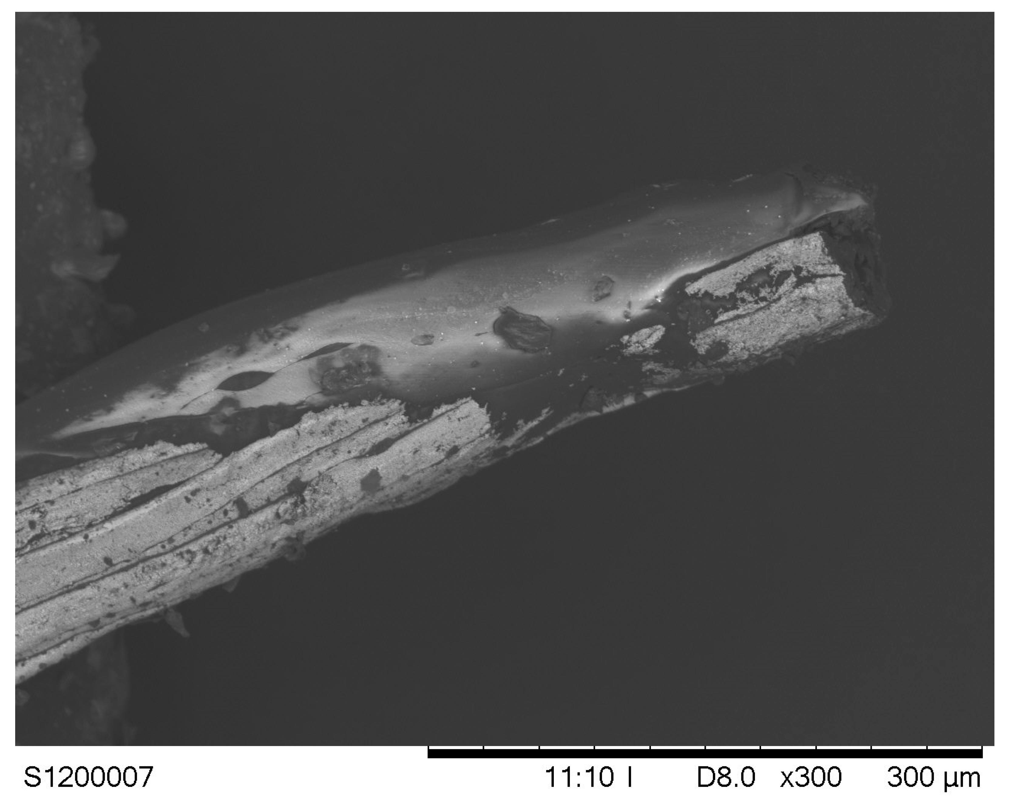
In
Figure 8, the same type of thread is shown after it has failed. The thread has physically split, and it is visible that at its end, the whole structure has formed a single object. It can be observed that these fibers which used to constitute the threads have all but disappeared in a single blob of molten polymer. The interesting part is that under SEM, polyamide, and in general polymers would appear as dark grey/black while here, there is an indication that the molten polymer has partially engulfed the silver plating close to the point of separation.
While the experiment was being carried out, a thermal camera (TI160, ULIRVision) was targeting the thread samples to provide an insight into the temperatures registered at the moment of breakdown.
Table 5 shows these values per thread type, as both in instantaneous and in continuous mode of testing, the threads were failing at comparative temperature values. That is expected, as these temperature values are slightly lower than the glass transmission temperatures of the polymers used in the fiber core. This indicated that the threads were not failing electrically, but structurally, as increased temperatures in the core making them soft and malleable, and under the effect of gravity (as catenaries) they separated.
4. Future Work
Even though this work established that the four studied conductive threads can sustain a substantial amount of power before they fail, the experiment was performed with free-standing threads. Therefore, an interesting potential future extension would be to repeat the experiment for threads already embroidered to some type of fabric or substrate, which will sever their convective abilities.
Moreover, as such work is very important for other researchers in the field of flexible and stretchable electronics as it provides very important observations in terms of electrical limits of used threads. This will guarantee that more reliable circuits will be made if the used electrical threads are within safe limits where their response is as expected; therefore, similar work of electrical characterization of additional threads can be realized in the future.
Additionally, another area to be explored could be how much heat can the wearer withstand, assuming the thread is part of some kind of wearable device, in direct contact with the skin. It might be the case that the maximum current carrying capacity of the threads could not be utilized in such a case. Therefore, further future work in the general thermal characterization of such threads is proposed, which will contribute with observations that will help designers of textile electrical circuits to achieve better reliability and stability of the expected performance.
The use of silver threads in AC circuits is expected to grow in the future as they can be part of various electrical structures for heating, wireless communications, or inductively coupled elements. Because of that, characterization of the silver threads in a wide range of frequencies will allow a better understanding of their behavior, and it is marked as a future work for our group.
Lastly, the threads could be examined under vacuum to remove the convective thermal dissipation altogether from the picture, and to establish what the absolute electrical limits of such threads are.
5. Conclusions
In summary, the scope of this work was to examine commercially available conductive threads with respect to their electrical properties, given that their manufacturers only give a nominal value for electrical resistivity.
Ten samples of each thread were successively used as a device under test, forming part of a voltage divider circuit, with a resistor of a known value. For five of them, the voltage was instantly being increased to their breaking point, and for five of them, this was happening in steps of 60 s.
There were three notable results observed. Primarily, the fact that every sample among the ones of the same thread has a much different resistance, and that is not so closely coinciding with the nominal value given. Secondly, the fact that each thread can support a higher power momentarily, compared to continuously, is in line with the physics describing electrical circuits, resistive heating, and convective heat transfer. Lastly but most importantly, the fact that the way the individual thread samples have been damaged is not consistent even among the samples of the same series or same family of threads. The last observation makes the need for further research in the thermal characterization of the threads even more prominent. Additionally, research in correlating the damages the threads have sustained from the moment they are fabricated to the moment they reach an end consumer should be realized. This could as well be coupled to damages sustained after the consumer builds a finished product with the threads, having subjected them to bends, stresses, and embroidery.
Overall, this work shows that even though the four studied conductive threads can sustain a significant amount of power for a prolonged period, users should tread cautiously, as their performance cannot at this stage be standardized, and their usability for precision applications might have to be further assessed. However, the power capacity of the individual threads might make them ideal candidates for applications such as woven/embroidered antennas or sensors.
Author Contributions
Conceptualization, G.M.S. and M.S.; methodology, M.S.; software, A.K.S.; validation, A.K.S., M.S. and G.M.S.; formal analysis, A.K.S.; investigation, M.S.; resources, A.K.S.; data curation, M.S.; writing—original draft preparation, A.K.S.; writing—review and editing, A.K.S.; visualization, A.K.S., M.S.; supervision, G.M.S.; project administration, G.M.S.; funding acquisition, G.M.S. All authors have read and agreed to the published version of the manuscript.
Funding
This research was funded through the European Union’s Horizon 2020 research and innovation programme under grant agreement No. 854194.
Data Availability Statement
The data presented in this study is available on request from the corresponding author.
Conflicts of Interest
The authors declare no conflict of interest.
References
- Gonçalves, C.; Ferreira da Silva, A.; Gomes, J.; Simoes, R. Wearable E-Textile Technologies: A Review on Sensors, Actuators and Control Elements. Inventions 2018, 3, 14. [Google Scholar] [CrossRef] [Green Version]
- Tangsirinaruenart, O.; Stylios, G. A Novel Textile Stitch-Based Strain Sensor for Wearable End Users. Materials 2019, 12, 1469. [Google Scholar] [CrossRef] [Green Version]
- Huang, T.; He, P.; Wang, R.; Yang, S.; Sun, J.; Xie, X.; Ding, G. Porous Fibers Composed of Polymer Nanoball Decorated Graphene for Wearable and Highly Sensitive Strain Sensors. Adv. Funct. Mater. 2019, 29, 1903732. [Google Scholar] [CrossRef]
- Wu, R.; Ma, L.; Hou, C.; Meng, Z.; Guo, W.; Yu, W.; Yu, R.; Hu, F.; Liu, X.Y. Silk Composite Electronic Textile Sensor for High Space Precision 2D Combo Temperature–Pressure Sensing. Small 2019, 15, 1901558. [Google Scholar] [CrossRef]
- Engin, M.; Demirel, A.; Engin, E.Z.; Fedakar, M. Recent Developments and Trends in Biomedical Sensors. Measurement 2005, 37, 173–188. [Google Scholar] [CrossRef]
- Huang, J.-S.; Jiang, T.-Y.; Wang, Z.-X.; Wu, S.-W.; Chen, Y.-S. A Novel Textile Antenna Using Composite Multifilament Conductive Threads for Smart Clothing Applications. Microw. Opt. Technol. Lett. 2016, 58, 1232–1236. [Google Scholar] [CrossRef]
- Ali, S.; Hassan, A.; Hassan, G.; Bae, J.; Lee, C.H. All-Printed Humidity Sensor Based on Graphene/Methyl-Red Composite with High Sensitivity. Carbon 2016, 105, 23–32. [Google Scholar] [CrossRef]
- Wang, X.; Liu, Z.; Zhang, T. Flexible Sensing Electronics for Wearable/Attachable Health Monitoring. Small 2017, 13, 1602790. [Google Scholar] [CrossRef]
- Kadara, R.O.; Jenkinson, N.; Banks, C.E. Characterization and Fabrication of Disposable Screen Printed Microelectrodes. Electrochem. Commun. 2009, 11, 1377–1380. [Google Scholar] [CrossRef]
- Kadara, R.O.; Jenkinson, N.; Li, B.; Church, K.H.; Banks, C.E. Manufacturing Electrochemical Platforms: Direct-Write Dispensing versus Screen Printing. Electrochem. Commun. 2008, 10, 1517–1519. [Google Scholar] [CrossRef]
- Hsu, S.L.-C.; Wu, R.-T. Synthesis of Contamination-Free Silver Nanoparticle Suspensions for Micro-Interconnects. Mater. Lett. 2007, 61, 3719–3722. [Google Scholar] [CrossRef]
- Lakafosis, V.; Rida, A.; Vyas, R.; Yang, L.; Nikolaou, S.; Tentzeris, M.M. Progress Towards the First Wireless Sensor Networks Consisting of Inkjet-Printed, Paper-Based RFID-Enabled Sensor Tags. Proc. IEEE 2010, 98, 1601–1609. [Google Scholar] [CrossRef] [Green Version]
- Matsuhisa, N.; Kaltenbrunner, M.; Yokota, T.; Jinno, H.; Kuribara, K.; Sekitani, T.; Someya, T. Printable Elastic Conductors with a High Conductivity for Electronic Textile Applications. Nat. Commun. 2015, 6, 7461. [Google Scholar] [CrossRef]
- Stoppa, M.; Chiolerio, A. Wearable Electronics and Smart Textiles: A Critical Review. Sensors 2014, 14, 11957–11992. [Google Scholar] [CrossRef] [PubMed] [Green Version]
- Ismar, E.; Zaman, S.; Bahadir, S.K.; Kalaoglu, F.; Koncar, V. Seam Strength and Washability of Silver Coated Polyamide Yarns. IOP Conf. Ser. Mater. Sci. Eng. 2018, 460, 012053. [Google Scholar] [CrossRef]
- Atwa, Y.; Goldthorpe, I.A. Metal-Nanowire Coated Threads for Conductive Textiles. In Proceedings of the 14th IEEE International Conference on Nanotechnology, Toronto, ON, Canada, 18–21 August 2014; pp. 482–485. [Google Scholar]
- Atwa, Y.; Maheshwari, N.; Goldthorpe, I.A. Silver Nanowire Coated Threads for Electrically Conductive Textiles. J. Mater. Chem. C 2015, 3, 3908–3912. [Google Scholar] [CrossRef] [Green Version]
- Irwin, M.D.; Roberson, D.A.; Olivas, R.I.; Wicker, R.B.; MacDonald, E. Conductive Polymer-Coated Threads as Electrical Interconnects in e-Textiles. Fibers Polym. 2011, 12, 904–910. [Google Scholar] [CrossRef]
- Alagirusamy, R.; Eichhoff, J.; Gries, T.; Jockenhoevel, S. Coating of Conductive Yarns for Electro-Textile Applications. J. Text. Inst. 2013, 104, 270–277. [Google Scholar] [CrossRef]
- Ruppert-Stroescu, M.; Balasubramanian, M. Effects of Stitch Classes on the Electrical Properties of Conductive Threads. Text. Res. J. 2018, 88, 2454–2463. [Google Scholar] [CrossRef]
- Atakan, R.; Acikgoz Tufan, H.; uz Zaman, S.; Cochrane, C.; Kursun Bahadir, S.; Koncar, V.; Kalaoglu, F. Protocol to Assess the Quality of Transmission Lines within Smart Textile Structures. Measurement 2020, 152, 107194. [Google Scholar] [CrossRef]
- Ismar, E.; uz Zaman, S.; Tao, X.; Cochrane, C.; Koncar, V. Effect of Water and Chemical Stresses on the Silver Coated Polyamide Yarns. Fibers Polym. 2019, 20, 2604–2610. [Google Scholar] [CrossRef]
- Dils, C.; Werft, L.; Walter, H.; Zwanzig, M.; Krshiwoblozki, M.V.; Schneider-Ramelow, M. Investigation of the Mechanical and Electrical Properties of Elastic Textile/Polymer Composites for Stretchable Electronics at Quasi-Static or Cyclic Mechanical Loads. Materials 2019, 12, 3599. [Google Scholar] [CrossRef] [PubMed] [Green Version]
- Schwarz, A.; Kazani, I.; Cuny, L.; Hertleer, C.; Ghekiere, F.; De Clercq, G.; De Mey, G.; Van Langenhove, L. Electro-Conductive and Elastic Hybrid Yarns–The Effects of Stretching, Cyclic Straining and Washing on Their Electro-Conductive Properties. Mater. Des. 2011, 32, 4247–4256. [Google Scholar] [CrossRef]
- MADEIRA Garnfabrik Technical Datasheet HC 12 2019. Available online: https://www.madeira.com/embroidery-solutions/embroidery-supplies/industrial-embroidery-threads/technical-threads/high-conductive-threads (accessed on 12 January 2021).
- MADEIRA Garnfabrik Technical Datasheet HC 40 2019. Available online: https://www.madeira.com/embroidery-solutions/embroidery-supplies/industrial-embroidery-threads/technical-threads/high-conductive-threads (accessed on 12 January 2021).
- AMANN Group AMANN TechX Brochure. Available online: https://www.amann.com/fileadmin/user_upload/AMANN_TechX_Brochure_EN.pdf (accessed on 2 February 2021).
- Tobler-Rohr, M.I. The supply chain of textiles. In Handbook of Sustainable Textile Production; Woodhead Publishing: Cambridge, UK, 2011; pp. 45–149. ISBN 978-0-85709-136-9. [Google Scholar]
- Eyerer, P.; Schüle, H. Polymer Engineering 1; Springer: Berlin, Germany, 2019. [Google Scholar]
- Adams, D.; Alford, T.L.; Mayer, J.W. Silver Metallization: Stability and Reliability; Engineering materials and processes; Springer: London, UK, 2008; ISBN 978-1-84800-026-1. [Google Scholar]
- von Krshiwoblozki, M.; Linz, T.; Neudeck, A.; Kallmayer, C. Electronics in Textiles–Adhesive Bonding Technology for Reliably Embedding Electronic Modules into Textile Circuits. Adv. Sci. Technol. 2012, 85, 1–10. [Google Scholar] [CrossRef]
| Publisher’s Note: MDPI stays neutral with regard to jurisdictional claims in published maps and institutional affiliations. |
© 2021 by the authors. Licensee MDPI, Basel, Switzerland. This article is an open access article distributed under the terms and conditions of the Creative Commons Attribution (CC BY) license (https://creativecommons.org/licenses/by/4.0/).


