1. Introduction
In recent years, either dedicated or cellular-based communication standards were developed across the globe to enable vehicular communication. Whatever the choice, standardization bodies keep in mind that vehicular communication has stringent requirements. Therefore, the frequency range was recommended by the International Telecommunication Union (ITU) [
1] to be in the range of 76–81 GHz in order to meet appropriate wireless solutions for automotive RadCom systems.
The concept of a RadCom system has been investigated since the early 2000s. However, combining two systems with different needs is not straightforward. Classical radar waveform designs aim at creating waveforms with optimal autocorrelation properties to minimize sidelobe levels in distance estimation, hence reducing its estimation errors. One of the most popular signals achieving such a property are linear frequency modulated pulses also known as “chirp” signals. Designing a RadCom system on this basis, however, heavily degrades the symbol rate, which is important for communication systems [
2].
To accommodate the needs of both systems, the use of multicarrier signals was proposed by Levanon in 2000 [
3] and 2002 [
4]. Compared to single carriers, which have only one dimension time domain, multicarrier waveforms are two dimensional systems where both time and frequency are used efficiently. This frequency diversity appealed to many other researchers who proposed to adopt orthogonal frequency division multiplexing (OFDM) as a RadCom waveform in [
5,
6]. The main advancements of this concept were proposed later on by Strum and al. and published in their invited paper [
7] in 2011. In their previous paper, the authors focused on the use of OFDM RadCom systems for vehicular applications. In fact, OFDM-based signals can easily provide the range and velocity estimation of targets surrounding the transmitter while offering robustness against multipath fading and simple equalization for communicating targets. However, OFDM is very sensitive to the Doppler shift, which can cause intercarrier interference (ICI), thereby deteriorating the communication aspect of the RadCom system. In addition, OFDM radar systems require a high cyclic prefix (CP) padded to the transmitted signal to preserve the time orthogonality of the modulation symbols and prevent intersymbol interference (ISI), but at the cost of reduced spectral efficiency since the CP part of the signal is not used for either detection or communication.
In order to overcome the shortcomings of CP-OFDM, multiple candidate waveforms for 5G were investigated over the course of the past few years. To relax the orthogonality condition, they rely on different designs of synthesis functions. Universal filtered multicarrier (UFMC) is one of the most attractive 5G waveforms candidates, and it was first introduced in [
8]. It offers a good trade-off between performance and complexity, and it is suitable for supporting multiple services [
9,
10]. Applying filtering per groups of subcarriers [
11] (namely, sub-bands), UFMC achieves low out-of-band (OOB) emissions while keeping the simplicity of OFDM [
12]. In fact, UFMC decomposes the frequency spectrum into narrow-band orthogonal subcarriers in the complex plane, making use of straightforward OFDM knowledge [
12]. More specifically, in the UFMC scheme, the entire band of subcarriers
is subdivided into
S sub-bands, with
Q subcarriers each, such that
Nc. Each sub-band is then filtered by a prototype filter of length
L and shifted to the appropriate sub-band frequency [
11]. As long as the same length of sub-band filter is used [
12], subcarriers in UFMC are orthogonal in the complex plane. Hence, UFMC can use quadrature amplitude modulation (QAM) constellation.
Moreover, a RadCom system must be able to operate over a multiuser V2X communication scenario; hence, the need for multiple-access techniques imposes itself. The use of code division multiple access (CDMA) with direct-sequence spread spectrum (DS-CDMA) was proposed in 2015 [
13] and earlier in 2006 in [
14]. This technique proved to have great range and velocity estimation while allowing for multiple users to share the same time–frequency resource using unique orthogonal codes. However, the conventional DS-CDMA spreads user data to a short-duration chip, causing a wide band transmission. In addition, a complex receiver is needed in order to reduce severe ISI. MC-CDMA, as presented in [
15], is an efficient multiple-access technique, where CDMA is associated with multicarrier waveforms to benefit from the simplicity of multicarrier modulation and demodulation while increasing the spectral efficiency provided by the superposition of multiple users. However, MC-CDMA studies were limited to only the OFDM waveform. Consequently, we chose to extend state-of-the-art work, combine CDMA with the UFMC waveform, and evaluate its performance in a vehicular environment.
In this paper, we propose a novel multiuser RadCom system where UFMC is used as the RadCom waveform instead of OFDM. The UFMC can offer great power efficiency thanks to the omission of the CP, and retain compatibility with the conventional OFDM signal, which achieves low system complexity. We also propose MC-CDMA as a multiaccess technique in order to support multiuser transmission and increase power efficiency. Meanwhile, the novel system is evaluated with and without MC-CDMA in terms of bit error rate (BER), and a mathematical analysis model of the BER is established and compared with the OFDM RadCom system. Moreover, while the UFMC filter is a key factor for this waveform performance, filter-length investigation is provided in order to conclude how it should be chosen to obtain optimal results.
This paper is organized as follows:
Section 2 focuses on the signal model of the RadCom system, radar processing, and system parametrization.
Section 3 is dedicated to the OFDM RadCom signal model.
Section 4 is devoted to the UFMC RadCom. BER simulation results and a discussion for both radar and communication scenarios, and filter-length analysis are presented in
Section 5. Lastly,
Section 6 concludes this work.
2. RadCom System Model and Processing
2.1. RadCom Approach
In RadCom systems, overall radio resources must be first shared between multiusers (multivehicles; hence the MA technique), and second between two functionalities, radar and communication. In the following sections, we adopted a time-division multiplexing (TDM) approach to separate both aspects of the RadCom system. TDM is a straightforward approach that we applied to the RadCom system by simply separating radar signals and communication signals over the time domain, as depicted in
Figure 1. Priority in terms of resource allocation is evidently given to the radar rather than communication due to the need for continuous detection. Nevertheless, the transmitter is always able to communicate; for instance, if the vehicle changes the cell, it needs to send a communicating message to the base station (BS). The transmitter sends repeated frames in order to detect the neighboring vehicles. After a certain delay
, it receives its reflected signal. This delay
induced to the signal is inherently related to the application constrains, such as the radar’s maximal detection range. However, other users may send communicating messages to the main user, thus interfering with the reflected signal, and detection is degraded. The TDM approach mainly indicates to the main user if he is either on a communication or a radar time slot in order to trigger the proper (radar/communication) receiver to decode the frame. This approach decreases the overall complexity of the RadCom system by overcoming the need for interference cancellation techniques. We chose the time-sharing method because it is the simplest approach for radar or communication integration. The goal of this study is to evaluate our proposition in vehicular channels. In the future, we aim to study other sharing approaches, such as frequency sharing and Sub-beamy.
2.2. Signal Propagation
Let
be a passband transmitted signal, where
is the carrier frequency, and
B is the bandwidth of
x. Considering multipath propagation, the passband received counterpart of
is expressed as:
where
denotes the number of propagation paths
, and
is the time-varying channel gain associated to the
l-th path. This model also accounts for multitarget cases.
The time-varying delay is due to the varying motion between transmitter (RadCom system) and receiver (targeted vehicle), and is given by the following expression:
where
c is the speed of light,
is the distance between RadCom transmitter and targeted vehicle at
. For simplicity, we omit the
subscript.
v is the relative speed at
[
16]. In this case, acceleration and higher-order motion were ignored. We introduced parameter
to model both the communication system and the radar using the same equation. In this case, 4cm0cm
Substituting (
2) in (
1), it follows that baseband received signal
is
where
is a constant delay,
is the motion-induced frequency shift, also known as the Doppler shift (Doppler shift is function of the carrier frequency and angle of arrival
of the
l-th path, such that
[
17],
is the maximal shift in this case). The term
is known as the time–scale factor [
18].
Equation (
3) implies that the received signal is the sum of attenuated Doppler-shifted (in frequency), time-stretched/-compressed (due to time scaling) and phase-shifted delayed copies of the transmitted signal. Phenomena of multipath propagation considering Doppler effects can be modeled as convolution with a filter, given as:
Equation (
4) is the impulse response of the channel. Its discrete-time counterpart considering a critically sampled model can be given as follows:
where
stands for sampling time, notation
is adopted, and
n stands for the time index.
2.3. RadCom System Model
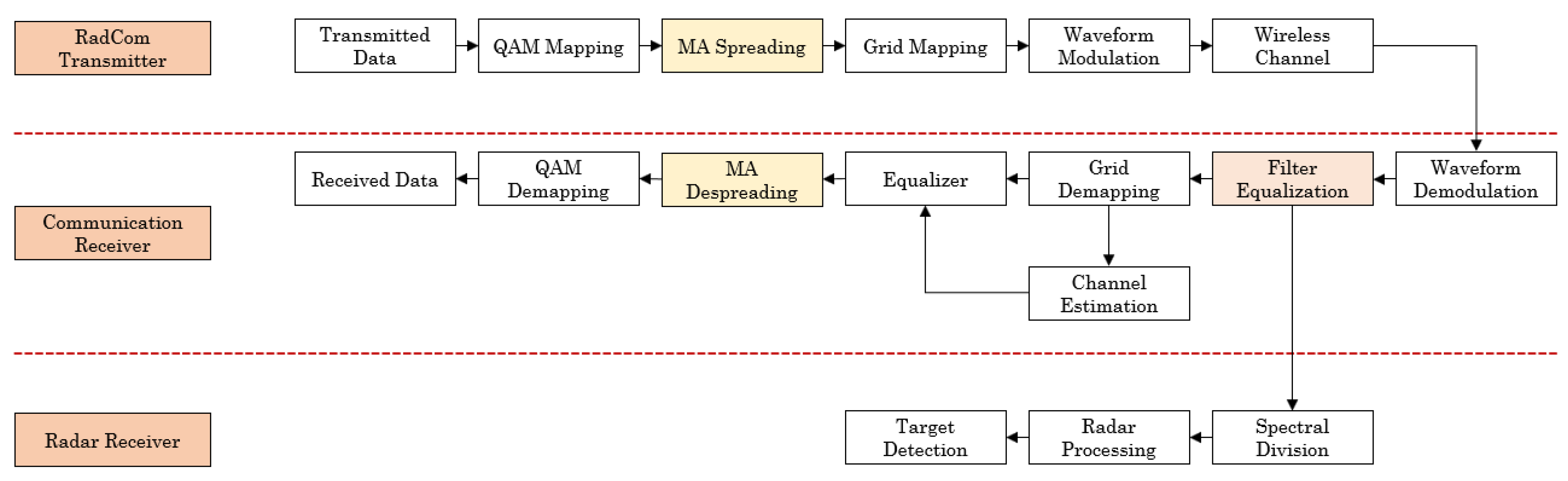
We consider a system model as depicted in
Figure 2. A data source generates random bits, which are then modulated using QAM mapping. Afterwards, the QAM symbols are rearranged in a time–frequency grid. For communication purposes,
pilots are inserted to be used in channel estimation at the communication receiver side. This grid is then shaped in multicarrier symbols using either UFMC or OFDM waveform before passing through the wireless channel following the model given in (
5).
At the receiver side, multicarrier symbols are demodulated using the corresponding waveform. Channel estimation is performed for both the communication and the radar system, but in different ways and for different purposes. For the communication system, the received frequency-domain pilots are first extracted to perform channel estimation using least-squares (LS) or minimum mean squared error (MMSE) estimation. Depending on the pilot arrangement, interpolation in the frequency or time domain (or both) is needed to estimate the channel at the nonpilot subcarriers of each symbol. Once the channel matrix is constructed, a simple zero-forcing equalizer is applied before QAM demodulation.
For radar, however, the entire transmitted signal grid is used to perform channel estimation. Below, we focus on explaining how this processing works, which is presented in the radar receiver section in
Figure 2.
Blocks represented in yellow are only needed in the case that MC-CDMA is deployed. User symbols are first spread over the frequency domain using unique uncorrelated codes before grid mapping, and despreading is only triggered by the communication receiver in order to decode the user signals.
In the receiver side, the MC-CDMA system suffers from huge performance degradation due to multiaccess interference (MAI) and ISI. Thus, many receivers implementing equalization and multiuser detection were studied for better interference mitigation. The first studied multiuser detector is the maximum likelihood (ML) detector, offering close to optimal results, but it is highly complex. Other blind joint equalizers, such as MMSE, were considered, but for a vehicular environment, training sequences are mandatory to perform multiuser detection, degrading the data rate on the other hand. In [
19], a two-stage receiver was proposed and proved to surmount many state-of-the-art receivers. In our case, this receiver could not be implemented due to its unsustainable implementation complexity in uplink scenarios. Regardless of all the above-mentioned receivers and their performance, we chose to implement a decorrelator receiver that was a single user detector that offered a great trade-off between performance and complexity.
Lastly, the “filter equalization” block, presented in pink, is used only for UFMC-modulated symbols.
2.4. Radar Processing
As we demonstrated in
Section 2.2, the channel equation fully contains information about distance and velocity. Hence, estimating these two parameters for radar is equivalent to the channel estimation for the communication system. The main difference is the use of the entire transmitted grid in radar instead of only a few pilots for communication.
On the basis of known transmitted symbols, raw channel estimation was first performed. For OFDM signals, it is expressed as
where
denotes the OFDM estimated channel,
the received signal, and
is the transmitted pilots for communication and the grid for radar. For UFMC, on the other hand, raw channel estimation at each subcarrier can be written as
where
denotes the UFMC estimated channel,
the received signal, and
means the subcarrier belonging to the
s-th sub-band.
is the known filter frequency response at this subcarrier. From Equations (
6) and (
7), it is clear that UFMC channel estimation only differs from the OFDM one by the filter response. Hence, in the system model diagram (
Figure 2), we propose to add a filter equalization block to account for the filter impact on the UFMC-received signal. This operation afterwards makes the UFMC signal equivalent to OFDM. Hence, below, we drop the
and
subscripts.
This first step of channel estimation is simply a spectral division of the received signal by the transmitted one; hence, in the system model diagram, we present it by its name: spectral division. After spectral division (and filter equalization for UFMC), the estimated frequency-domain channel transfer function
at
q-th subcarrier for the
r-th symbol (ignoring the stretching and compression effects) can be given by
where
describes the subcarrier spacing,
denotes the additive white Gaussian noise of the
q-th subcarrier for the
r-th symbol;
is the OFDM symbol length, where
denotes Fast Fourier transform (FFT) length, and
is CP length. Equation (
8) shows that the delay (hence, range) can be estimated using inverse FFT (IFFT) over the frequency axis. The Doppler shift (hence, velocity) can be evaluated using FFT over the time axis. This is equivalent to applying a 2D periodogram, as depicted in
Figure 3. The main advantage in this approach is that the delay and Doppler estimations are independent. At first, this operation estimates frequency
and symbol
indices, which should then be translated to distance and velocity through the following equations:
and , where denotes the total number of the transmitted symbols, and N and M are the FFT and IFFT length of the 2D periodogram, respectively. is the total duration of the OFDM symbol.
Deciding if a peak in the periodogram is a true target is basically a statistical detection problem that boils down to binary hypothetical testing. Hypotheses can be formulated as in Equation (
11), where in
, the received signal is noise, and in
, the received signal is the target-reflected one, propagating through the channel plus the noise.
To decide between the two hypotheses, a test static
, which is a function of the received signal, is computed and compared to a threshold
, such that:
The result of the comparison of the test statistics with the threshold in Equation (
12) is obtained from the probability density function (PDF) of the test statistic under
versus the PDF under
.
In radar processing, power detection is adopted. Hence, the threshold can be expressed as [
20]:
where
is false-alarm probability, and
is noise power. More details are provided in [
20].
2.5. Waveform Parametrization
To allow for the proper parametrization of a RadCom waveform, the following criteria should be respected for both communication and radar systems:
: where is the maximal expected delay spread to avoid ISI,
: to avoid ICI
: to achieve spectral efficiency.
Subcarrier spacing is limited by the maximal Doppler shift, hence the speed of the target, while the cyclic prefix is limited by the delay, hence the target’s distance. These two parameters add additional constraints for the radar. Maximal unambiguous distance is determined by subcarrier spacing
as follows:
which also determines the distance resolution:
is bandwidth. Furthermore, maximal unambiguous velocity is determined by the symbol time (denoted
to account for both OFDM and UFMC):
which also determines the distance resolution:
is observation time.
4. UFMC RadCom Signal Model
The UFMC discrete-time baseband signal is the superposition of the sub-bandwise filtered subcarriers [
11]; therefore, it can be expressed as follows:
where ⊗ denotes linear convolution, and
is the filter used in the
s-th sub-band. It is defined in (
21) as:
with
being the prototype filter of length
L, and
denoting the starting frequency of the lowest sub-band.
is the
s-th group of subcarriers, which is an OFDM symbol shifted to the appropriate sub-band. It is given by (
22):
where
are complex symbols transmitted on the
q-th subcarrier in the
s-th sub-band during the
r-th period. They are spread over the overall signal and transformed into the time domain, with inverse discrete Fourier transform (IDFT) of length
. Term
performs frequency shifting of both data and filter coefficients to the appropriate sub-band. Because of convolution, the resulting UFMC signal is of length
. The filtering operation makes it possible to suppress the OOB leakages, with the Dolph–Chebyshev filter being the most common in the literature [
11].
Replacing (
21) and (
22) in (
20), and applying some simplifications, the transmitted UFMC signal can be written as in (23).
with
being the prototype filter shifted to the sub-band center frequency [
11]. Considering the same channel model as for OFDM, the received UFMC signal can be expressed as follows:
Figure 4 depicts the synthesis of a UFMC signal.
BER Analytical Model
In this subsection, we elaborate an analytical model of the BER. The analytical expression of the M-ary QAM modulation over additive white Gaussian noise (AWGN) is given by Equation (
24).
where
M is the modulation order,
denotes
, and
Q is defined as the
Q function:
BER calculation is easily performed using the following approximation of the
Q function:
Hence, for OFDM, the BER over each subcarrier can be deducted from the Equation (
24). However, as subcarriers in the UFMC system are being filtered, noise variance on the
subcarrier of the
sub-band is then divided by the equivalent filter response and can be expressed as follows.
Thus, the BER expression of the
subcarrier of the
sub-band can be written as
5. Simulation Results
In this section, some simulations and discussions are illustrated. We verify the proposed approach of UFMC and UFMC-CDMA RadCom systems and compare it with that of an OFDM RadCom system. First, the performance of the radar system is examined and compared with that of OFDM. Afterwards, UFMC and UFMC-CDMA communication systems are evaluated over different channels and compared with OFDM. Spreading sequences and filter-length simulations are provided for both radar and communication to find how they either degrade or enhance overall performances. All simulated scenarios were performed in MATLAB.
5.1. Radar-System Performance Evaluation
Table 1 summarizes the simulation parameters that were chosen according to the design criteria presented previously in
Section 2.5.
For targets, we chose to simulate 4 targets in which 2 targets shared the same distance and very close velocity to verify velocity resolution. Target 1 at a distance m with velocity m/s, Target 2 with m and m/s, Target 3 at a distance m distance m and m/s, and Target 4 with m and m/s. The UFMC parameters adopted in this case were sub-band size and filter length was 16 for optimal performance.
In a vehicular context, relevant maximal target distance does not exceed m. Considering the sampling time of the signals, receivers can efficiently mitigate the effect of ISI, when maximal delay is within the CP duration for OFDM. For UFMC, on the other hand, the filter ramp-up and -down at the edges of the symbol guarantees soft protection against ISI. The energy contained in the L last samples of the UFMC signal is relatively small. However, the choice of filter length also impacts the correct estimation of target distance and velocity, since energy is not equal among all subcarriers.
Figure 5 depicts the periodogram of the two received signals computed using the parameters in
Table 1. Results confirmed that both suggested waveforms are suitable for radar, as we can clearly see the four targets on the distance–velocity grid. Furthermore, the UFMC waveform reduces the high OOB power emission while retaining the simplicity of the conventional OFDM signal. This also offers increased spectral efficiency due to the omission of CP.
While UFMC proved to be suitable for radar application as a new 5G waveform, we suggest to implement MA techniques, more specifically CDMA, to study how the spreading can affect obstacle detection. The spreading sequences that we chose in our simulation are the Walsh–Hadamard sequences because of their ease of implementation, high autocorrelation, and low cross-correlation properties. The order of the used sequences is , and the evaluation of radar performance is performed with different scrambling patterns. The nature of the spreading sequences used by the transmitter changed the outcome of the simulation.
As depicted in
Figure 6, we chose three Walsh–Hadamard codes with the same length, categorized as follows: a nonscrambled sequence, which is a sequence of ones, and usually the first generated sequence in the Hadamard matrix; the second code is more scrambled compared to the first and sequels 64 chips of the same binary codeword; the last sequence is the most scrambled sequence that could be generated. By choosing these three configurations, we implemented both worst- and best-case scenarios, and a third case to back up the overall results.
In order to illustrate the difference between the three codes,
Figure 7 depicts the periodogram of UFMC-CDMA. The nonscrambled sequence yielded severe deterioration to the received signal compared to the other sequences, while the high-scrambled sequence presented optimal results. Interferences induced to the transmitted signal by its own echos in this multipath environment decreased the probability of detection due to constant energy spreading. Consequently, in order to minimize interference resulting from the presence of multiple copies of the spread signal, the use of a scrambled signature sequence divides the signal energy differently over all subcarriers, optimizing radar-system performance.
5.2. Communication-System Performance Evaluation
In this subsection, we compare the performance of the communication system of the UFMC scheme with OFDM over a multipath vehicular channel with different Doppler frequencies, in particular, the tapped delay line A (TDL-A) channel. The TDL-A channel model has a Doppler spectrum that is characterized by Jake’s spectrum shape. The power delay profile (PDP) of the model is presented in [
21], and the delay spread used to scale the normalised tap delays was
. This delay spread was chosen to correspond to a short delay profile in a UMi Street-canyon for a 70 GHz carrier frequency to match the carrier frequency of our RadCom system.
Seven-symbol slots were considered in the transmission system, and pilot-aided channel estimation was used in our simulations. We chose to insert pilot symbols in the grid according to two different configurations. In the frequency domain, the positions of the pilots were determined by pilot spacing. In our case, we fixed the pilot spacing to 4; hence, 512 resource elements (RE) were allocated for pilots. For the time domain, we chose a low-density configuration where only the first symbol was allocated for pilots, and high-density configuration where the first and the fifth symbols were allocated for pilot symbols. For complexity and enhancement considerations, it is more interesting to use the MMSE channel estimator and ZF equalizer.
While communicating, the system parameters are updated for optimization reasons. First, subcarrier spacing is reduced to 15 KHz for optimal spectral efficiency; hence, sampling frequency is also reduced. Moreover, the total number of transmitted symbols is no longer fixed at 175 symbols and becomes flexible depending on the requirements of the transmitter. No error-correction coding was deployed. For UFMC-CDMA, we added multiuser interference (MUI) with 3 different patterns, where 5, 6, and 7 users were superimposed at each subcarrier for each pattern, respectively.
As presented in
Figure 8, the high-density configuration slightly outperformed the low-density configuration; however, the overall performance of both OFDM and UFMC waveforms was highly degraded due to the high delays induced by the TDL-A channel. Comparing the previous figures shows that the gap between the pilot configurations is more significant over a higher maximal Doppler shift i.e., a higher speed. This is due to the time-domain enhancement of the pilot insertion. With regard to waveform comparison, UFMC and OFDM exhibited the same BER performance, while UFMC offered the great advantage of OOB reduction and increased the overall spectral efficiency.
Regarding UFMC-CDMA, the TDL-A channel delays and patterns of interference between served users directly impacted the BER. System performance degraded as the number of users became larger, as shown in
Figure 9. However, even for the long delays induced by channel and filter selectivity, UFMC-CDMA showed improved overall performance.
5.3. Filter-Length Analysis
The last stage of our simulations was filter-length analysis, where we defined the filter length that is suitable for the RadCom application. We mainly fixed the SNR to 10 dB and performed both detection and communication to observe how filter length can either improve or worsen the performance of the UFMC RadCom system.
The frequency selectivity of the filter is is what makes UFMC signal well-localized in the frequency domain and reduces OOB emissions. However, filter-frequency selectivity may cause system performance loss, as
Figure 10 shows. When filter length increases, selectivity among subcarriers increases. On the basis of these results, we recommend that filter length should be chosen to be proportional to the number of subcarriers divided by sub-band size
.
Figure 10 also shows that UFMC-CDMA, even with a high-scrambled signature sequence, suffered from the same deterioration as that caused by filter-frequency selectivity.
Regarding the communication aspect of the RadCom UFMC system, we evaluated filter length only over an AWGN channel and with different sub-band sizes for a better comparison.
The BER versus filter-length curves for different sub-band sizes are presented in
Figure 11. By increasing sub-band size and filter length, overall performance was degraded. For the case of
, the BER was at
dB for a filter length that ranged from 2 to 128. However, for
, the BER began to rapidly degrade as soon as the filter length reached
. For other sub-band cases, degradation was close to
. Hence, optimal filter-length configuration
L should be chosen to be smaller than
for optimal performance.
6. Conclusions
In this paper, UFMC, as a new 5G waveform, and UFMC-CDMA were proposed as a RadCom system, and they proved to be suitable for this application by means of simulations while offering great radar and communication performance. First, the OFDM and UFMC waveform parametrization and the UFMC-CDMA signal model details were described. An analytical model of the UFMC BER was also provided. On the basis of RadCom system requirements, multiaccess techniques can be implemented to support a V2X multiuser environment; consequently, simulations were performed with and without multiaccess. The UFMC waveform is capable of supporting a RadCom system with affordable complexity, similar to OFDM, while offering optimal spectral efficiency. In addition, filter length was investigated, and filter length should be chosen to be smaller than for communication, Regarding radar requirements, it should be chosen to be proportional to . As for UFMC-CDMA, it was proven that the choice of spreading sequence can affect the overall performance of the radar. The more scrambled the sequence is, the more optimal results are. Furthermore, filter-frequency selectivity affected UFMC-CDMA performance. The performed simulations did not hold any error-correction coding; thus, added error correction coding would enhance system performance.


 ,
, 


