Article

Enabling Parallelized-QEMU for Hardware/Software Co-Simulation Virtual Platforms

1
Department of Electronics, University of Alcalá, 28801 Alcalá de Henares, Spain
2
Department of Applied Mathematics, Materials Science and Engineering and Electronics Technology, Rey Juan Carlos University, 28933 Móstoles, Madrid, Spain
*
Author to whom correspondence should be addressed.
Electronics 2021, 10(6), 759; https://doi.org/10.3390/electronics10060759
Submission received: 30 January 2021 / Revised: 9 March 2021 / Accepted: 19 March 2021 / Published: 23 March 2021
(This article belongs to the Section Computer Science & Engineering)

Abstract

:
Presently, the trend is to increase the number of cores per chip. This growth is appreciated in Multi-Processor System-On-Chips (MPSoC), composed of more cores in heterogeneous and homogeneous architectures in recent years. Thus, the difficulty of verification of this type of system has been great. The hardware/software co-simulation Virtual Platforms (VP) are presented as a perfect solution to address this complexity, allowing verification by simulation/emulation of software and hardware in the same environment. Some works parallelized the software emulator to reduce the verification times. An example of this parallelization is the QEMU (Quick EMUlator) tool. However, there is no solution to synchronize QEMU with the hardware simulator in this new parallel mode. This work analyzes the current software emulators and presents a new method to allow an external synchronization of QEMU in its parallelized mode. Timing details of the cores are taken into account. In addition, performance analysis of the software emulator with the new synchronization mechanism is presented, using: (1) a boot Linux for MPSoC Zynq-7000 (dual-core ARM Cortex-A9) (Xilinx, San Jose, CA, USA); (2) an FPGA-Linux co-simulation of a power grid monitoring system that is subsequently implemented in an industrial application. The results show that the novel synchronization mechanism does not add any appreciable computational load and enables parallelized-QEMU in hardware/software co-simulation virtual platforms.

1. Introduction

The emergence of Multi-Processor System-On-Chip (MPSoC) with homogeneous and heterogeneous processor architectures has increased the difficulties of hardware (HW) and software (SW) designs and their verification [1].
Companies such as Xilinx, Intel, or ARM provide devices that integrate MPSoCs. These devices integrate software resources, also called the Processing System, which are linked with Field-Programmable Gate Arrays (FPGA), also called Programmable Logic. These devices can combine the flexibility of the software, such as Operating Systems (OS) or bare-metal applications, with the high-performance hardware designs, such as hardware accelerators and sophisticated Intellectual Property (IP) modules. However, since it is necessary to simulate the behavior of the whole system to verify the platform, i.e., software and hardware, and their intercommunication; the verification of these devices is intricate.
To reduce this difficulty, virtual platforms are presented as a perfect solution for evaluating whole systems and analyzing hardware/software proposals before their implementation stage. These virtual platforms use hardware/software co-simulation techniques profusely described in the literature [2,3,4]. In those, the software and hardware designs are combined at different levels of abstraction and with different timing accuracy. Their use allows verifying designs without the need for real boards, which dramatically reduces costs and verification time. Nevertheless, the main limitation is the low speed of this co-simulation.
Typically, three options have been used to speed up co-simulation. Since simulation speed depends on the number of triggered events, one option is to use a higher abstraction level, which requires fewer triggered events. To that end, this work presents a virtual platform that allows using SystemC language to describe hardware, as in [5], and Transaction Level Modeling (TLM) to model communications [6].
Another alternative is to parallelize the resources of virtual platform, focusing on the hardware or software simulators. In recent years, Moore’s Law has stagnated due to the physical limitations of the current technology [7]. To continue offering higher performance, the current trend consists of increasing the number of CPUs. Thus, significant efforts to parallelize the software simulators and adapt them to new challenges have been described in the literature.
The last option is based on emulation or virtualization. The emulation and virtualization allow using the host’s hardware resources to run the guest’s full system. Hence, you can get quick emulations or achieve native performance. Therefore, most tools apply techniques to emulate software behavior rather than simulate it, decreasing debugging features and increasing execution speed.
The synchronization carried out in a co-simulation virtual platform is essential to obtain correct results. Even though there are works that have advanced in the parallelization of the software emulator (see Section 2.1), they have not addressed the synchronization of the software emulator with other applications (i.e., the hardware simulator).
Our work analyzes the current software emulators in the market and presents an external synchronization mechanism for QEMU (Quick EMUlator), the most compatible open-source software emulator. The synchronization mechanism modifies the original QEMU proposal for Multi-Thread translator (parallelized mode) [8], used to increase co-simulation performance. The modifications enabling the use of parallelized-QEMU to emulate multi-core embedded devices in hardware/software co-simulation virtual platforms.
The proposed mechanism does not introduce a substantial overhead in the QEMU speed. This novel solution allows running hardware/software co-simulations in a fast way, jointly simulating Processor Subsystem and Programmable Logic in a few minutes.
The rest of the manuscript is organized as follows: background and proposal description are discussed in Section 2; the new method proposed to allow external synchronization in QEMU is presented in Section 3; the experimental results are exposed in Section 4; finally, the conclusions are discussed in Section 5.

2. Background and Proposal Description

2.1. Hardware/Software Co-Simulation Virtual Platforms

A virtual platform is a software tool that allows the simulation of the design to be verified. Its use allows verification from simple designs to full systems using different levels of abstraction. Besides, the concept of co-simulation is related to add and synchronize multiple simulators or emulators in the same virtual platform to verify the whole system.
The most used strategy to build a hardware/software co-simulation virtual platform is based on a Discrete Event Simulator (DES) or simulation kernel, which distributes the tasks between the software design (CPU–Processing System) and the hardware design (FPGA fabric–Programmable Logic) [9,10,11]. Each hardware/software design can be seen as a module within the discrete event simulator. Moreover, each module can be made up of a simulator/emulator, and its synchronizations and communications are carried out through messages. Both modules can be described at different abstraction levels depending on the precision/speed trade-off that the user can assume.
In a discrete event simulator, state changes occur only through events [9]. The simulation run time increases with the number of triggered events. Therefore, a usual approach to improve simulation speed is to use higher abstraction levels with fewer events.
As it has been stated in multiple works [11,12], the best abstraction level to verify both software and hardware designs is the transaction level, which is detailed enough to check designs with timing accuracy but does not consider all the details of gate level that would slowdown the simulation.
The most common approach to build a virtual platform consists of an open-source processor emulator to reproduce the behavior of the software execution, such as QEMU [13] or Gem5 [14]; and a hardware simulator such as SystemC, which enables modeling the hardware designs from the algorithm level to the Register-Transfer Level (RTL).
In this setup, the processor emulator is made up of an Instruction Set Simulator (ISS), which interprets guest instructions and executes them on a host. It also involves a Bus Functional Model (BFM), which models the external processor interface and its connection with the surrounding hardware. Simultaneously, the hardware simulator behaves as the simulation kernel to distribute the simulation events in hardware/software modules (see Figure 1).
In this setup, both the software and hardware modules can introduce a high computational load, which implies a very slow simulation of a complex system. However, its use is very suitable during the early stages of the design flow.
FPGA-based SoC devices increase the complexity of hardware/software designs and, hence, their verification. Also, a trade-off between the timing accuracy and the speed of the simulation is observed. To carry out the verification of software binaries, it is necessary to simulate the hardware design located in the FPGA. The reason is that the software results will largely depend on the hardware results. For mixed hardware software designs, the difference of timing accuracy between the two is usually three or more orders of magnitude. A difference like this requires increasing the global timing accuracy of co-simulation, rising the number of processed events. Therefore, due to the need to synchronize both hardware and software components, it is essential to provide an efficient interface to verify the transactions between software and hardware.
SystemC and TLM 2.0, proposed as IEEE standard in 2011 and based on C + +, have become the most common languages to build hardware/software interfaces for co-simulation virtual platforms. Some examples are QBox [13], COREMU [15], Simics by Wind River Systems [16], or PetaLinux by Xilinx. These co-simulation virtual platforms allow instantiating RTL modules modeled in SystemC and using the native kernel (DES) of SystemC as hardware simulator and kernel of co-simulation. However, the SystemC kernel runs the simulation sequentially and has code limitations that prevent it from parallelizing its kernel [17,18]. Therefore, it introduces a penalty on complex FPGA-based SoC systems with multiple CPUs and RTL modules running in parallel. Contributions to parallelize SystemC are presented in [19]. However, these contributions have not yet been included in the OSCI SystemC Standard [6]. Also, their use is limited to the academic field.
To reduce long co-simulation run times, some virtual platforms such as PetaLinux or QBox have delegated the responsibility to the software emulators they adopted. This way, they focus on improving the interface, memory management, or the ecosystem. Like COREMU, others have chosen to create multiple modules to instantiate copies of the same software emulator in different threads and control their progress. However, they have not presented a follow-up of the work, and their impact has been diminished.
Table 1 shows the current most commonly used open-source software (SW) emulators. They are OVPsim, Unicorn, Gem5, and QEMU. The main reasons for their success are their high portability to different architectures and their updated repository and extensive documentation. This has led companies such as ARM, Xilinx, or Synopsys to adopt them for their products.
OVPsim is a private virtual platform emulator released by Imperas, which simulates complex multiprocessor platforms with arbitrary local and shared-memory topologies [20,21,31]. It offers open-source CPU models and free Application Programming Interfaces (APIs) to build processor, peripheral, and platform models. OVPsim’s main advantages are extensive documentation and support for different processor architectures. However, OVPsim does not allow building cycle-accurate models but rather instruction-accurate models [22]. Moreover, [22] shows that OVPsim is slower than QEMU. Also, it supports fewer hardware processors.
Gem5 is a microarchitecture simulator. Nevertheless, it supports a full-system mode, which enables it to be used as an emulator. It provides cycle-accurate precision since it is based on a DES. Therefore, its simulation speed is not as high as QEMU or OVPSim, both of which take advantage of a Dynamic Binary Translation (DBT) engine or the Kernel-based Virtual Machine (KVM) engine. Although the use of KVM is extended to virtualize desktop machines [32], its use to verify embedded devices is not very extended.
QEMU is currently the open-source instruction-accurate software emulator adapted to the largest number of hardware processors. Initially, it was created using a sequential execution. However, the increase in the number of CPUs (or cores) has forced researchers to look for alternatives such as the KVM engine or the Multi-Thread Tiny Code Generator (MTTCG) engine. These options speed up simulations of operating systems [8], parallelizing the load of QEMU in the host CPUs. Multiple works have been published describing its use to build high-performance hardware/software co-simulation environments [11,13,20]. Instruction-accurate is considered enough for functional verification of MPSoCs [22].
As a simplified version of QEMU, Unicorn [27] improves the framework and flexibility of QEMU, thus making a safe software emulator. Nonetheless, it offers fewer features than QEMU, and it has been ported to only a few hardware platforms. Its use is limited to research purposes [29].
Two main approaches have been used to include QEMU as software emulator within the co-simulation virtual platform: mono-process approach and multi-process approach.
In the mono-process approach used in [13,33], QEMU is included as a dynamic library in the virtual platform. Thus, the software emulator and the hardware simulator run in the same process, allowing the synchronization and communication mechanisms to be implemented as simple function calls.
The multi-process approach is based on the use of an inter-process communication mechanism. The last versions of PetaLinux tools by Xilinx include a new feature to allow the connection of QEMU to an external simulation environment, such as SystemC. This approach integrates simulators (QEMU and SystemC-DES) as different OS processes and sends transactions and synchronizes time through UNIX sockets. Such a solution provides flexibility. Nevertheless, the main weakness is the limited simulation speed it provides. This applies specifically to high I/O rates in which the inter-process communication overhead significantly reduces the co-simulation speed. This is an important aspect when the synchronization message rate is high. Another disadvantage of the QEMU emulator is that the multi-host thread feature is not supported, forcing the reduction of simulation speed and sequential execution. Therefore, its use in the verification of OS where multi-core systems are growing is limited.
QBox or “QEMU in a box” [13] is an in-progress solution to develop a QEMU version equipped with a TLM2.0 external interface to facilitate its integration in a hardware simulation environment. This virtual platform allows co-simulation using SystemC, and it provides shared libraries that contain QEMU-based CPU models. Currently, QBox only supports three types of ARM CPUs. Although it is a desirable open-source solution for heterogeneous architectures, currently it does not support the multi-host thread for fast OS simulations (similar to PetaLinux).

2.2. QEMU as Software Emulator

QEMU (Quick-EMUlator) is a fast processor emulator using Dynamic Binary Translation (DBT) to achieve fast emulation speed [8,23]. It is an open-source virtualization platform that allows cross-platform execution of operating systems and bare-metal applications. Dynamic binary translation makes it possible to run binary code generated for target (or guest) processor (e.g., ARM-Zynq Board) on another host processor, which has an entirely different instruction set (e.g., Intel i9). This means that it translates the instructions of the target CPU into the instructions of the host CPU. Then, it executes the instructions on the host CPU.
The guest CPU instructions are organized in basic Translation Blocks (TB). A translation block is a guest instruction sequence that executes without branches, except at the end of the block. A jump instruction signals the end of a block.
Presently, QEMU supports a wide range of processors (like x86, ARM, MIPS, or RISC), PCI peripherals, serial ports, graphic cards, and more services. In 2012, Xilinx included QEMU in its PetaLinux tool suite to verify embedded operating systems. Currently, it supports emulation of MPSoCs Xilinx families as Zynq or Zynq UltraScale, and Versal as well. However, even though these families have multi-core microprocessors, the tool only uses a single host-core for co-simulation due to the QEMU main loop limitations.

2.3. Parallelized-QEMU Project

In response to the current trend of increasing the number of CPUs or cores per device, a parallelized-QEMU project was launched. The Multi-Threaded Tiny Code Generator (MTTCG) project was included in QEMU 2.9. It allows the translator of QEMU to run one host thread per guest CPU (also known as virtual CPU or vCPU). Some platforms, such as PetaLinux, use this feature to speed up the OS emulation [8].
Currently, it is a work-in-progress project designed to provide full multi-threading support in additional system emulations. Some changes were introduced in the translator code to migrate from a single-thread solution (where vCPUs are executed sequentially) to a one thread per vCPU solution. These changes mainly affect the code dealing with the memory consistency, the execution of atomic instructions, the management of the blocks translated by each vCPU, and dirty page tracking [13,25]. Figure 2 shows the internal QEMU architecture using the MTTCG mode, in which there is a direct assignment of each guest CPU to each thread in the host CPU.
QEMU-MTTCG achieves high performance through the parallelization of the emulation computational load. In addition, to reduce the code translation operations, once a translation block has been translated for a given vCPU, this translation can be reused by other vCPUs in need to execute that piece of code. For this purpose, a cache hierarchy that centralizes all translation blocks translated by each vCPU has been added [25].
However, the notion of time remains as an unsolved task in this new multi-thread case. In fact, when the multi-thread mode is selected, the QEMU instruction counter is automatically disabled. Our work presents a solution to obtain the software notion of time from the time of each vCPU.

2.4. Proposal Description

The need to emulate multicore embedded devices has motivated some projects to advance in the parallelization of the QEMU-DBT. As a consequence, a new parallel translation engine called Multi-Thread TCG (MTTCG) has been developed.
However, in this new parallel mode, the synchronization of the QEMU with an external application (i.e., the hardware simulator) has not been resolved. This synchronization is fundamental in order to include QEMU in a hardware/software co-simulation tool. It should be noted that this tool is highly valuable for the verification of mixed hardware/software designs implemented in embedded devices such as MPSoCs + FPGAs.
This paper focuses on enabling a synchronization mechanism between QEMU and an external hardware simulator using the QEMU parallel emulation mode (MTTCG). This allows to verify multi-core applications and hardware designs in a co-simulation virtual platform using parallelized-QEMU. Our solution to add the external synchronization mechanism proposed in QEMU is based on three main points:
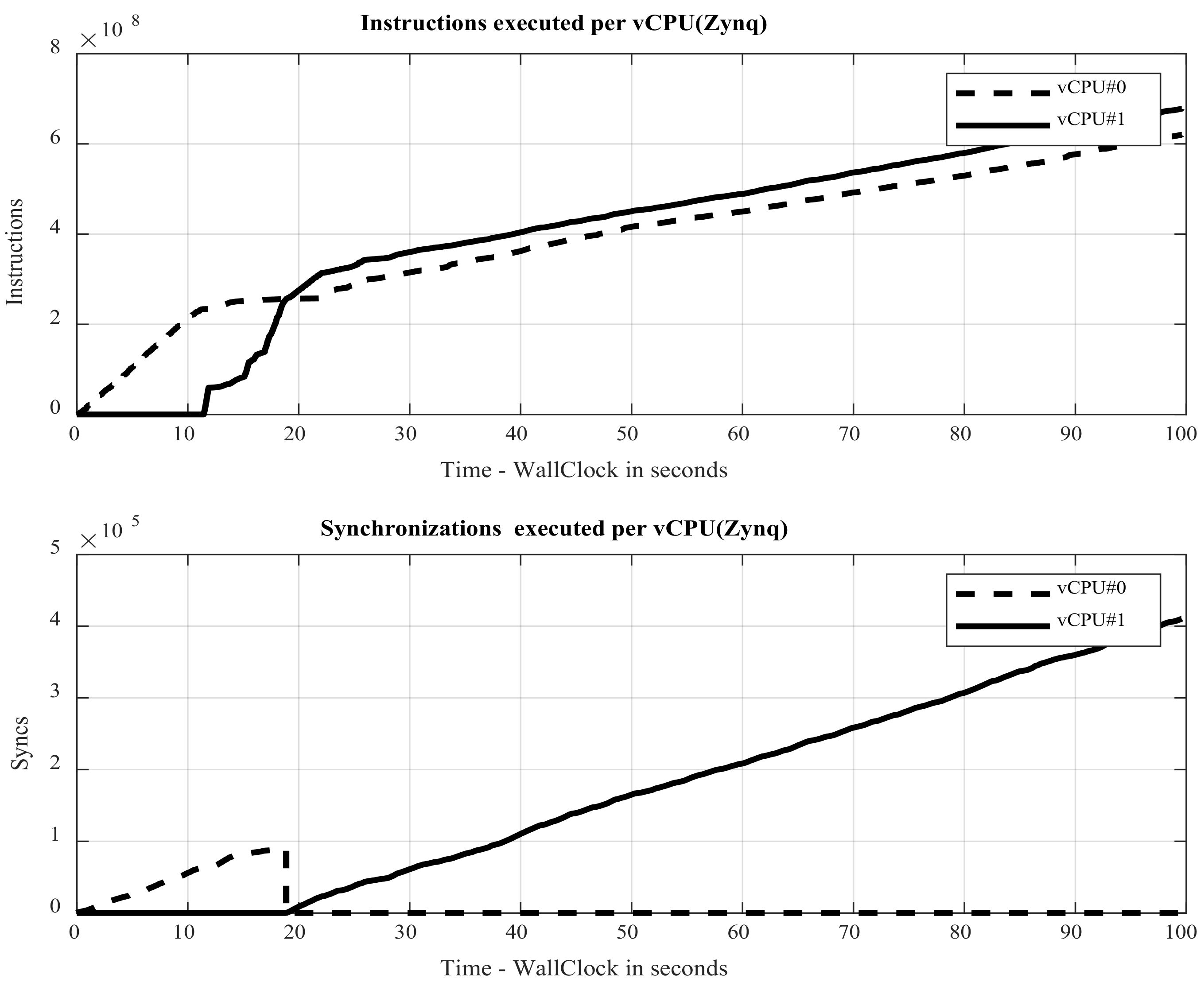
  • A procedure to obtain the number of instructions executed by each processor in a multicore emulation. The notion of time for each virtual CPU can be calculated from this instruction counter, providing an approximately timed processor model.
  • A method to break the QEMU translation loop and execute a synchronization point with the hardware simulator. This is critical as to not affect the performance of QEMU translation loop and achieve fast emulations.
  • A method to manage the software timing notion from hardware simulator point of view in multi-core systems. A synchronization between the external hardware simulator and the software emulator (QEMU) is essential to allow a correct co-simulation.
The mechanism proposed does not introduce appreciable overheads in the QEMU speed. The aforementioned improvements presented in this work allow running hardware/software co-simulations in a fast way.

3. QEMU External Synchronization Mechanism

QEMU-MTTCG was chosen as the software emulator for this paper. The main reason is that QEMU, together with Gem5, is one of the most widely used emulators for research purposes and the industrial field. Additionally, it has more available architectures. However, from the two previously mentioned options, only QEMU is able to emulate the Xilinx Zynq and UltraScale+ families, which integrate MPSoC and an FPGA fabric in the same die.
To use QEMU as a software emulator in a co-simulation environment, a synchronization is required to enable it running jointly with a hardware simulator or other external modules. This section describes the changes required to integrate QEMU in a co-simulation environment.
It is essential to define an interface to communicate and synchronize the hardware simulator and the software emulator whenever there is a hardware/software interaction. In every interaction, the state of each module and its time advance must be shared between them. These interactions can be classified into three types:
  • Input/Output (I/O) accesses from software to hardware (physical).
  • Asynchronous interrupts (physical).
  • Synchronization points (virtual).

3.1. Hardware/Software Interactions

For each memory range assigned to a hardware module, QEMU uses a memory-mapped (MMIO) object to detect input/output access targeted to this range. The MMIO object performs a call to the write()/read() processing functions to manage the access to that memory range. These write()/read() functions work as callbacks and block QEMU execution until they return. The functions receive arguments that provide all the access/transaction attributes (address, size, data, and time) and notify the hardware simulator about these events. In response, the hardware simulator uses this information to update the target modules. The QEMU execution is resumed once the target device concludes the transaction.
In the case of asynchronous interrupts, QEMU does not check if a hardware interrupt is pending for every translation block. When QEMU is notified that a new interrupt is triggered, an event is generated and added to the QEMU events queue. After the interrupt event is processed, the interrupt is sent to the virtual Generic Interrupt Controller (vGIC). Once this happens, the vCPU is notified of an interrupt exception [8]. Nevertheless, there is a delay between the moment when the hardware triggers an interrupt and the moment when the vCPU is notified. This is caused by the large number of events that QEMU must schedule and handle. To solve this issue and avoid timing error, our solution blocks the hardware simulator until the QEMU scheduler attends to the interrupt and vGIC is notified. Figure 3 depicts the differences of interrupt management for the real board case versus QEMU case (Virtual board case), when an Interrupt ReQuest (IRQ) is triggered.
The synchronization points represent the instants in which the hardware/software modules are synchronized to prevent one simulator/emulator from lagging behind another. They become essential when there are no input/output accesses or interrupts. Unlike input/output accesses and interrupts, this type of interaction does not represent a real physical interaction but is an internal mechanism to synchronize both simulators/emulators. Synchronization points are the most frequently generated interactions; therefore, they should be as fast and light as possible. They also become a mechanism to control the temporal precision of the software emulator.

3.2. The Notion of Time in QEMU

QEMU was not developed to model the CPU timing. Instead, it is an instruction-accurate emulator, made using a sequential execution. It is accepted that an instruction accuracy is enough to perform a functional verification for most of the MPSoC applications. Few papers have offered solutions to obtain timing modeling of the CPUs in QEMU. In [11] a fast cycle-accurate instruction set simulator, based on QEMU, is presented. It models the processor pipeline to obtain cycle-accuracy. It uses a very basic approach to model the data hazard. This is valid for the considered scalar processor (ARM9). However, described techniques are difficult to extend to modern and more sophisticated processor. The work [34] describes a QEMU-based simulator for modern superscalar out-of-order processor. It models the cache controller and the branch predictor to achieve a cycle-approximate accuracy. In [35] proposes to mix OVPSim with QEMU to get timing derails of caches and Translation Lookaside Buffers (TLBs). Previous papers only provide specific solutions that cannot be extended to all the machines on the market. In addition, to obtain a cycle-accuracy, these solutions introduce an extra overhead that reduces the simulation speed.
In QEMU and other platforms that integrate QEMU, such as QBox or PetaLinux, this aspect has been simplified, using the number of guest instructions executed on the host to measure the elapsed time. Due to this, QEMU has instruction-time precision. The number of instructions executed by QEMU is defined by an internal guest instruction counter updated when an entire translation block is executed on the host.
Let’s us consider the case of a processor with a single vCPU. The time advance can be obtained by Equation (1) where cn is the number of cycles it takes to execute the n-th instruction (MOV, AND, SUB, ADD, etc.). TCLK is the period of the CPU clock, and kcache-n is a factor that considers the influence of cache misses or branch misprediction on in n-th instruction. N is the total number of executed instructions.
Δ t C P U = n = 1 N c n · T C L K · k c a c h e n T C L K · C P I · N
This paper focuses on adding a synchronization mechanism to QEMU-MTTCG to enable its use in fast hardware/software co-simulation virtual platforms. Since we plan to use these virtual platforms to validate MPSoC design for application fields that require long simulation times, the simulation speed is a critical factor. Due to the aforementioned limitations of cycle-accurate models together with the high simulation speed requirement, some simplifications have been applied to Equation (1). Firstly, the cache influence has not be taken into account, therefore kcache-n = 1. Also, the period of the CPU clock (TCLK) is assumed to be constant. The number of cycles per instruction (cn) can be approximated by its average value (cycles per instruction (CPI)). Although the CPI is obtained for a specific benchmark, it can be considered to be a reliable reference to characterize the average performance of the processor. To use the CPI rate, we can assume the time advance is proportional to the number of executed instruction N, with TCLK · CPI being a constant term.
QEMU only emulates CPUs concurrently when it uses KVM or MTTCG. Only one thread is available in other setups to perform the translation sequentially using a round-robin approach. In this case, QEMU uses only one counter to count the total number of instructions executed by all vCPUs. In the MTTCG case, since the vCPUs execute these instructions in parallel instead of sequentially, the total number of executed instructions are not proportional to the elapsed time, causing a timing error. Figure 4 depicts this timing error on an example of dual-vCPUs running in single-thread mode (Figure 4a), compared with a correct case operating in multi-thread mode (Figure 4b). Each block represents the time elapsed between two consecutive interactions (A, A’, B, B’, …), and the numbers represent the order in which the blocks are used to increment the total software time. The arrows indicate which block is used to increment the software time at each instant. Please note that in the single-thread case, a timing error appears because in the parallel case, the sum of each CPU time is not the total time of the software.
Figure 4b shows the desired software timing flow in case there is more than one vCPU. The software emulator time (TOTAL in Figure 4) must be obtained from the vCPU that has executed the highest number of instructions (in this case, vCPU#1).

3.3. Implementation of External Synchronization in QEMU-MTTCG

Synchronization points allow the software emulator to send time and status messages to the hardware simulator to maintain successful synchronization in the virtual platform. This section explains how the code changes in QEMU-MTTCG in order to introduce the synchronization points.
To carry out this proposal, it is necessary to define three aspects. The first one is the QEMU code place where the synchronization points can be inserted safely. Second, the required changes to obtain the state information of each vCPU that it must be sent to the hardware simulator. The last one defines the method to manage the synchronization points in the QEMU running under MTTCG mode. Each one of these three aspects are described below.

3.3.1. Location of the Synchronization Points

The translation-execution loop is based on a translation from the Translation Blocks guest to the Translation Blocks host and its subsequent Translation Blocks execution on the host. Figure 5 shows the QEMU flow and where to introduce the synchronization point.
When an internal/external event needs to break the translation-execution loop, an exception is triggered. The exceptions force to store the state of the vCPU and break the translation-execution-loop in a secure mode. Thus, it allows the remaining processes of QEMU or peripherals to be updated before serving the exception. This is the right time to send a synchronization message to the hardware simulator since the state of the vCPU is safe and does not change. It should be noted that in the multi-thread case, this point can be reached at the same time by different vCPUs. For this reason, a mutex has been introduced to serialize and protect simultaneous access to the synchronization point. The exceptions of QEMU are triggered by multiple reasons, which are described below. However, there are more factors to trigger an exception described in QEMU documentation [8]:
  • Exceeding the maximum limit of instructions executed (icountMax). This exception enables carrying out other pending tasks and processing events associated with the management of the whole emulated system. The icountMax value is the maximum limit of instructions executed in a translation-execution loop (in Equation (1), it equals variable N) and is user-configurable.
  • An external interaction toward the vCPU. Which is any signal that is generated outside vCPU flow and modifies its state (i.e., asynchronous interrupts).
  • Other exceptions generated by the guest code. Most of them are related to the guest code, the QEMU management of the vCPUs, and the emulated peripherals.

3.3.2. vCPU Instruction Counter

To obtain the number of instructions executed by the vCPU, our new proposal is based on the method applied in the single-thread case, avoiding the loss of compatibility with the original case. During the translation phase, assembly instructions are added at the beginning and the end of each host Translation Blocks (TB). These instructions are also called the prologue (P) and the epilogue (E) of the TB (see Figure 6). The prologue (P) accesses the instructions counter of each vCPU, located in the vCPU structure that defines its state. The epilogue (E) increases the instruction counter with the number of equivalent TB guest executed instructions. Thus, the number of executed instructions for each vCPU is updated during the execution phase.
Initially, QEMU keeps only one instruction counter shared among all vCPUs. In this paper, an instruction counter has been included in each vCPU structure. Also, its access from the prologue and epilogue has been guaranteed.

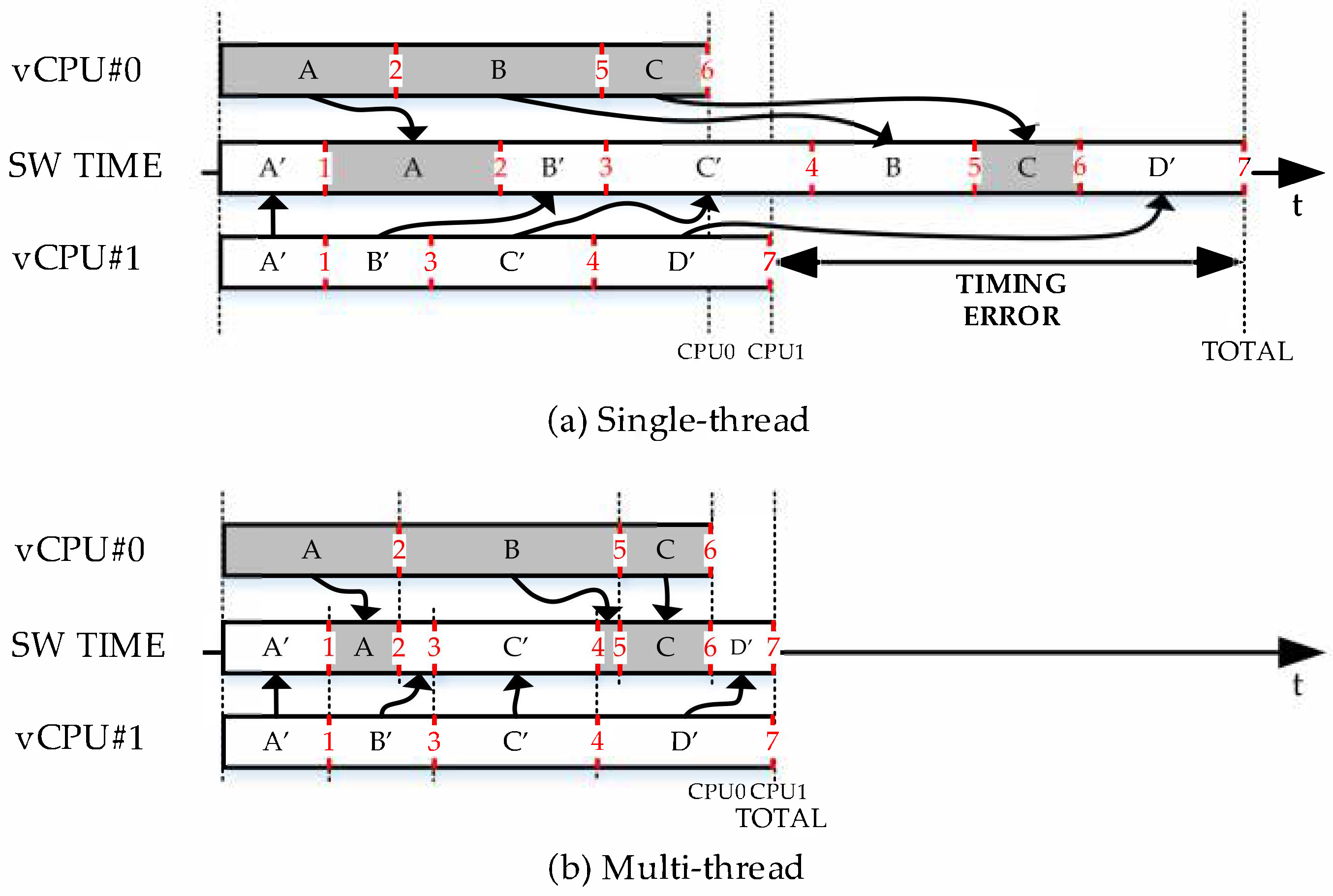
3.3.3. Management of Synchronization Points

Given that each vCPU has its instruction counter, the simulated time [9] of each vCPU (local simulated time) can be obtained from Equation (1). The main factors that determine the speed of instruction execution of each vCPU are as follows:
  • Instructions shared between vCPUs. The synchronization in parallel execution of vCPUs is guaranteed by QEMU-MTTCG when an instruction affects multiple vCPUs. As with DES, the affected vCPUs are blocked until all vCPUs reach the same simulation time. Otherwise, and for most of the instructions, the instructions of each vCPU are executed as fast as possible [25].
  • The structure of the guest code in each vCPU is decisive in its speed of execution. A complex structure of the guest code means that QEMU will make more translations and changes to the TB cache table. Therefore fewer executions will be chained, decreasing the performance of the vCPU simulation.
  • The workload of the machine/OS on which QEMU runs. Therefore, the speed at which QEMU executes its instructions can change in function on the host OS load.
The above features produce time differences between the vCPUs. To guarantee that a vCPU with less executed instruction does not update the notion of the time of the software emulator (simulated time), the time values sent to the hardware simulator must be monotonically increasing. Otherwise, it would generate an inconsistency in the time of the hardware simulator. It should be noted that this condition also eliminates the influence of the number of vCPUs on the total number of generated synchronization points. This is because the number of synchronization points will depend only on the vCPU that has executed the highest number of instructions, achieving the diagram described in Figure 4b.
Since multiple vCPUs can trigger synchronization points at very close instants, a threshold has been introduced to control the minimum number of instructions that must be executed before the next synchronization point happens.
For these reasons, the following expression has been included as a condition of a synchronization point where TSW is the time of the software emulator and is equal to the maximum time of all vCPU; THW is the time of the hardware simulator; Tht is the minimum time that the software emulator can advance in the co-simulation virtual platform.
s y n c = 1 , T S W = max T v C P U n   > T H W + T h t 0 , o t h e r w i s e

4. Test and Results

This paper aims to integrate QEMU-MTTCG in a co-simulation virtual platform that uses the SystemC kernel as Discrete Event Simulator manager and hardware simulator. The presented external synchronization mechanism is essential to synchronize QEMU-MTTCG as the software emulator with the hardware simulator. Within the virtual platform, QEMU is instantiated as a dynamic library. Besides, a TLM 2.0-based API has been developed to provide the necessary communication infrastructure between QEMU and the hardware simulator.
The test and results section presents the influence of virtual interactions (synchronization points) and physical interactions (Input/Output/interrupt).
A Linux (MPSoC Zynq-7000-ARM Cortex-A9 dual-core) has been used, such as in [14], to test virtual and physical interactions and using different setups. To test virtual interaction, it will run the Linux boot and the ParMiBench benchmark, which is specialized in multi-core embedded devices. Then, to test physical interactions, a real project of a hardware/software system will use it.
The simulation performance can be calculated as the ratio between the guest simulation time considered by our virtual platform and the time consumed to run the simulation, also known as wallclock time [9]. Since the co-simulation virtual platform is executed under an operating system, the running time is not deterministic and can vary. Therefore, each setup runs ten tests, and the average and variance of the host execution time (wallclock time) have been calculated.

4.1. Overhead of Virtual Interactions in Co-Simulation

The next tests analyze the impact of the virtual interactions, which means the number of synchronizations (N_SYNC) in the co-simulation. No hardware module was added to isolate the influence of the changes introduced in the software emulator. Neither one tested any physical interaction with the hardware. Furthermore, it was checked that the time of hardware simulator is correctly synchronized with the software emulator.
To compare the overhead in the co-simulation introduced by the modifications in QEMU-MTTCG, three different setups have been tested using a Linux boot.
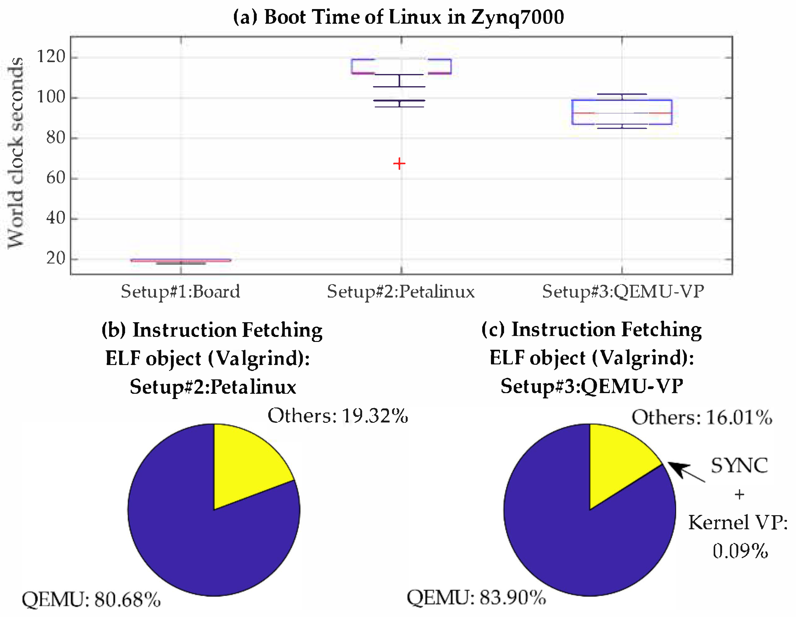
  • Setup#1: Real board. Linux boot in the physical system (ZedBoard-Zynq7000).
This test shows the real execution time in the real platform.
  • Setup#2: QEMU-PetaLinux. Linux boot using QEMU-MTTCG provided by PetaLinux. This setup shows the execution time using the QEMU version included in PetaLinux. Therefore, we selected this version as star point to apply our solution.
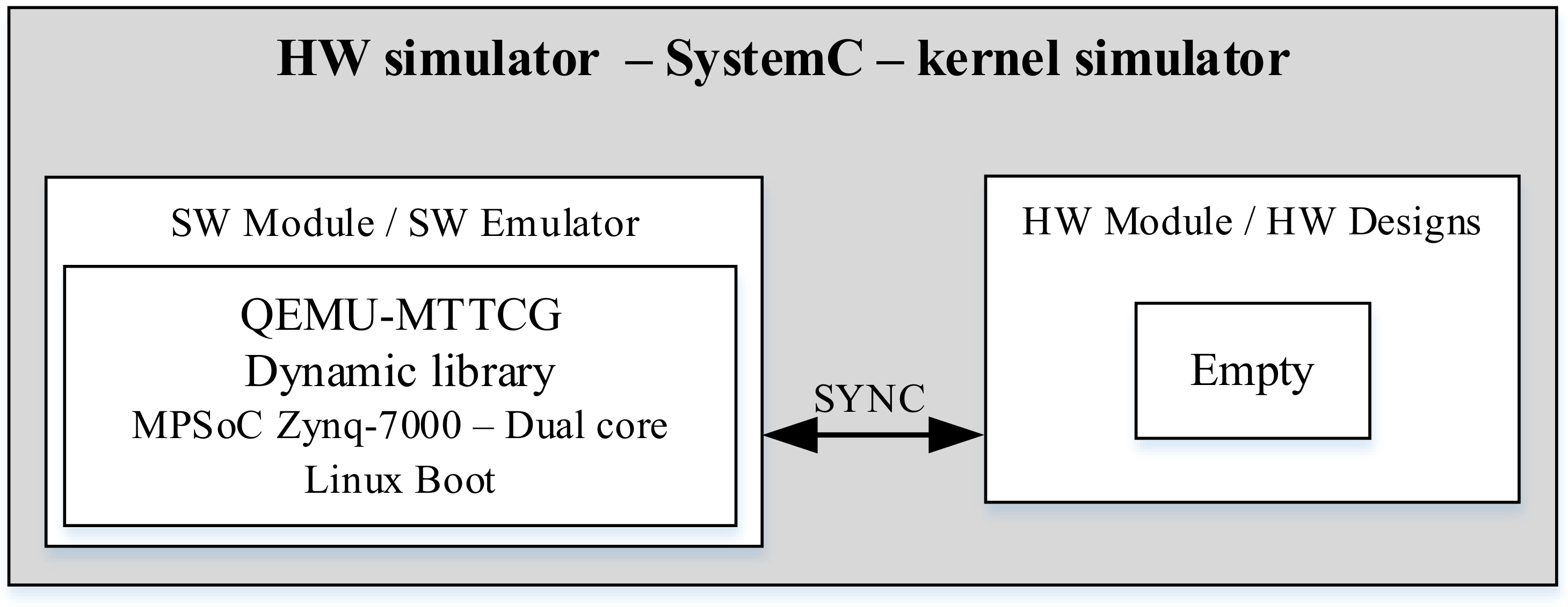
  • Setup#3: QEMU-VP. (QEMU for virtual platforms) Linux boot using the version of QEMU-MTTCG patched with our external synchronization mechanism. In this setup, QEMU is included in a SystemC-based Virtual Co-simulation Platform (see Figure 7).
Figure 7. Setup#3. QEMU-MTTCG inside a co-simulation virtual platform as software (SW) emulator.
Electronics 10 00759 g007
In previous setups, the number of synchronizations performed between the software emulator and the co-simulation kernel is evaluated. The results are in function with the Tht threshold value (see Equation (2)) and the maximum limit of instructions executed by the QEMU translation-execution loop (icountMax). Besides, the overhead introduced by the number of synchronizations on the simulation speed is analyzed.
Multiple tests have been carried out using Setup#3, sweeping the Th and icountMax parameters. In each test, the number of synchronizations and the wallclock time consumed in a Linux boot has been measured. These test results are shown in Figure 8, using a logarithmic scale for all the axes. As it can be observed in Figure 8a, the number of synchronizations can be controlled by the icountMax and Th parameters, as indicated by Equation (2). It can be seen that the number of synchronizations shoots up exponentially as Tht and icountMax parameters are diminished.
However, Figure 8b shows that the icountMax parameter is the only one with a real impact on the software emulation’s wallclock time (wallclock in seconds). Thus, it can be concluded that the value of the Tht parameter by itself does not influence the host simulation time or wallclock time. Hence, providing the user with a handy mechanism to define the timing precision of the software emulator. The reason is that icountMax forces the QEMU translation-execution loop to break when icountMax instructions are executed. This stopping breaks the chains between the TBs, decreasing the high performance of the QEMU translator-execution loop, consequently slowing down its simulation speed significantly.
It should be noted that icountMax represents the maximum limit of the software timing precision. By default, its value in QEMU is 216. For compatibility reasons and based on the study carried out in this work, this value must not be modified to preserve the high performance of QEMU unless it is necessary to have higher timing precision for the software emulator. In any case, icountMax is user-configurable from our virtual platform.
Figure 9a shows that the Linux boot execution times for Setup#2 (QEMU-PetaLinux) and Setup#3 (QEMU-VP) with our modifications are similar. Thus, it is demonstrated that the changes made do not generate a significant overhead for virtual interactions.
Furthermore, execution times are reduced since PetaLinux runs more management processes that slow down the simulation.
Profiling techniques have been used to get the overhead introduced by the virtual interactions. Figure 9b,c show the results obtained with Valgrind during the simulation for Setup#2 (QEMU-PetaLinux) and Setup#3 (QEMU-VP). As it can be observed, the modifications introduced to allow the integration of QEMU-MTTCG on our co-simulation virtual platform has a small impact on run time, and it does not exceed 0.1% of instructions executed.
The ParMiBench benchmark was used in order to measure the overhead when executing other types of applications different from a Linux boot. ParMiBench [36] is a benchmark specialized in multiprocessor-based embedded systems. It is a parallelized version of MiBech and specializes in the embedded devices. ParMiBench provides four categories: Automation and Industry Control, Network, Office, and Security. In this case, the benchmark was executed by directly launching QEMU-PetaLinux, which prevents the overhead added by the PetaLinux managing scripts. Table 2 summarizes details on these applications and the inputs used for each case.
Figure 10 shows the results of the execution time taken for each ParMiBench applications. Tests have been done for Setup#2-QEMU-PetaLinux and for Setup#3-QEMU-VP. The figure shows the relative increment of the wallclock time for QEMU-VP when compared with the QEMU-PetaLinux. Consequently, a result of 5% means that QEMU-VP is 5% slower than QEMU-PetaLinux.
To conclude, a Linux boot running in a QEMU-MTTCG for a co-simulation virtual platform only increases the execution time by 5× when compared with the real platform (Figure 9a Setup#1(Board) versus Setup#2(QEMU-VP)). Furthermore, the modification applied in our solution does not introduce a substantial overhead (less than 10%) when running ParMiBench applications.
Figure 11 shows the instructions and synchronizations executed by each vCPU in the first 100 seconds (wallclock) of the Linux boot in Setup#3, and it reflects the behavior described by Equation (2). In Zynq, CPU#0 behaves as the Master CPU; hence, vCPU#0 is the first to boot the system and later wakes up vCPU#1. This behavior can be seen in the first 10 seconds of Figure 11 Top. Figure 11-bottom shows the CPU it has the preference to synchronize. When vCPU#0 is the only active core, all synchronizations are generated by it. Once the vCPU#1 wakes up, and the number of instructions executed by vCPU#1 is more significant than vCPU#0, the synchronizations are no longer managed by vCPU#0.

4.2. Overhead of Physical Interactions in Co-Simulation

This section analyzes the effect of physical interactions between the software emulator and the hardware simulator, i.e., input/output (IO) access and interrupts. To isolate the effect of physical interactions in the co-simulation, both icount and Th remain constant.
A real project of a power grids monitoring system has been chosen as a case study. This system allows checking the synchronization between the software and the hardware in a real application. It also periodically exchanges information between the software simulator and the hardware simulator through input/output accesses and interrupts.
The power grids monitoring system’s architecture can be seen in Figure 12 and is based on a hardware/software design. The hardware/software co-design is composed of an embedded Linux (dual-core) that runs an application to obtain data on the power grid state. The application accesses the FPGA or the hardware when it detects an interrupt (IRQ) from the FPGA. This interrupt indicates that the data obtained by the hardware is ready to be read. The hardware design is made up of two hardware accelerators described at the RTL level and at medium complexity. The first accelerator is a signal acquisition module (IP-ADC). The IP-ADC reads the voltage and current sensors of the power grid. The second hardware accelerator is called IP-PLL and reads data from IP-ADC. Then, it calculates the frequency, phase, alpha-beta transformation, and Direct-quadrature-zero transformation of the power grid. The IP-PLL uses a Sequence Detector based on SOGI (Second-Order Generalized Integrator), plus a Phase-Locked Loop (PLL) with Backward integration. It has been designed using High-level synthesis tools, as described in previous works [37]. When the PLL finishes performing its calculations, it saves the results in a Dual-port BRAM memory. Then, it generates the interrupt which indicates to the Linux Application that the data can be read. Once Linux reads the power grid data from BRAM memory located in hardware, it sends it over MODBUS (Ethernet) to a supervisor. The FPGA clock frequency is 100 MHz, and the hardware ADC and PLL accelerators run periodically, generating an interrupt every 100 µs. Both hardware accelerators consume 9.54% of Slices, 14.55% of DSPs, and 1.78% of BRAMs memories from the FPGA (Zynq-7000).
Figure 13 shows a frame of the co-simulation results with the input/output events (physical interaction) and synchronization (virtual interaction) events. These are generated in each periodic interruption (100 µs). One read access per 100 µs is executed, which means a 32-bit access per interrupt (40 KB/s). The triangle symbols time the instant an event is generated. The IO_EVENT signal indicates the start of an input/output access event, and the SYNC_EVENT signal indicates a synchronization event between the software emulator and the hardware simulator. It can be seen that for each interrupt, Linux accesses the hardware through an input/output access. Therefore, Linux detects the interruption, wakes up the Application, and executes read access to hardware. The time from when the interrupt is triggered until Linux accesses the hardware is the Linux response time. The large number of synchronization events that are seen allows keeping the software emulator and hardware simulator in sync with a timing precision of 1 µs.
To analyze the overhead of input/output accesses in the co-simulation, a sweep of the number of inputs/outputs has been carried out, which will increase the number of writes/reads that are executed for each interruption (every 100 µs). In each test, one second is simulated with a precision of 10 ns in the hardware simulator. The maximum CPU IO throughput programmed for the Zynq-7000 is 25 MB/s [38], for this reason, tests have been performed up to this value. The results of multiple tests are shown in Figure 14a and, as shown, even though the input/output rate is increasing, there is no appreciable change in the wallclock or the running time of the co-simulation. This is because the computational load of the hardware simulator and QEMU is higher than the virtual and physical interactions, even though it used the highest input/output rate supported by the real board.
To check the overhead of the input/output accesses and interrupts on the host, profiler tests have been used again. Taking the highest input/output rate understudy, Figure 14b shows that most of the host instructions, which are executed by the virtual platform, are focused on the hardware simulator. While, despite having a high input/output rate (25 MB/s), only 0.007% of instructions are dedicated to the management of the input/output/interrupt and the synchronization between the software emulator and the hardware simulator. This shows that the synchronization mechanism included in QEMU-MTTCG does not add any appreciable computational load for physical interactions compared to the computational load of a real hardware/software co-simulation.

5. Conclusions

This paper presents a new proposal for integrating QEMU as a software emulator in co-simulation virtual platforms based on SystemC. The integration enables fast MPSoC + FPGA verification using QEMU’s MTTCG parallel execution mode.
The new proposal is based on a synchronization mechanism between the QEMU and an external hardware simulator. The synchronization mechanism sends messages to the hardware simulator and uses the coherency time described for QEMU. Moreover, the mechanism allows setting the timing precision of the QEMU with a low impact on the co-simulation run time or wallclock time.
A quantitative analysis of the proposal and real tests have been carried out to analyze the new proposal’s overhead in co-simulation. These experiments verify the impact of virtual and physical interactions between software emulator and hardware emulator for a Linux Boot, different typical software applications and an FPGA-Linux co-simulation of a real industrial application. The results show the slight effect of the proposed external synchronization mechanism in QEMU’s runtime and the co-simulation.
To conclude, the results show that the new proposal allows including parallelized-QEMU in hardware/software co-simulation virtual platforms without adding substantial overhead. It also allows taking advantage of the software emulator’s parallelization to reduce the execution time of the co-simulation in real projects.

Author Contributions

Conceptualization, R.M., E.J.B. and E.D.; methodology, R.M. and E.D.; software, R.M. and E.D.; formal analysis, E.D.; investigation, R.M., E.J.B., R.N. and E.D.; writing—original draft preparation, E.D.; writing—review and editing, R.M., R.N., E.J.B. and E.D.; visualization, E.D.; supervision, R.M. and E.J.B.; project administration, R.M.; funding acquisition, R.M. and E.J.B. All authors have read and agreed to the published version of the manuscript.

Funding

This work has been supported in part by the Spanish Ministry of Science, Innovation, and Universities through the RETOS 2017 project, RTC-2017-6262-3.

Acknowledgments

The authors would like to thank Slavka Madarova for her huge support in English review.

Conflicts of Interest

The authors declare no conflict of interest.

References

  1. Rodriguez-Andina, J.J.; Valdes-Pena, M.D.; Moure, M.J. Advanced Features and Industrial Applications of FPGAS-A Review. IEEE Trans. Ind. Inform. 2015, 11, 853–864. [Google Scholar] [CrossRef]
  2. Wu, Y.; Fu, L.; Ma, F.; Hao, X. Cyber-Physical Co-Simulation of Shipboard Integrated Power System Based on Optimized Event-Driven Synchronization. Electronics 2020, 9, 540. [Google Scholar] [CrossRef] [Green Version]
  3. Kim, M.; Kim, S.W.; Han, Y. EPSim-C: A Parallel Epoch-Based Cycle-Accurate Microarchitecture Simulator Using Cloud Computing. Electronics 2019, 8, 716. [Google Scholar] [CrossRef] [Green Version]
  4. Xu, B. Boyi Xu; Li Da Xu; Hongming Cai; Cheng Xie; Jingyuan Hu; Fenglin Bu; Ubiquitous Data Accessing Method in IoT-Based Information System for Emergency Medical Services. IEEE Trans. Ind. Inform. 2014, 10, 1578–1586. [Google Scholar] [CrossRef]
  5. Mendoza, F.; Pascal, J.; Nenninger, P.; Becker, J. Framework for dynamic verification of multi-domain virtual platforms in industrial automation. In Proceedings of the IEEE 10th International Conference on Industrial Informatics, Beijing, China, 25–27 July 2012; pp. 935–940. [Google Scholar] [CrossRef]
  6. Design Automation Standards Committee. Standard IEEE Standard for Reference SystemC® Language Manual; IEEE Standards Association: New York, NY, USA, 2011. [Google Scholar]
  7. Duraton, M.; De Bosschere, K.; Coppens, B.; Gamrat, C.; Gray, M. HiPEAC Vision. UGent: Ghent, The Netherlands, 2019. [Google Scholar]
  8. QEMU. QEMU Official Web Page. Available online: https://www.qemu.org/ (accessed on 21 December 2020).
  9. Fujimoto, R.M. Parallel and Distributed Simulation Systems, 1st ed.; John Wiley & Sons, Inc: Hoboken, NJ, USA, 2000. [Google Scholar]
  10. Weinstock, J.H.; Murillo, L.G.; Leupers, R.; Ascheid, G. Parallel SystemC Simulation for ESL Design. ACM Trans. Embed. Comput. Syst. 2016, 16, 1–25. [Google Scholar] [CrossRef]
  11. Chiang, M.C.; Yeh, T.C.; Tseng, G.F. A QEMU and SystemC-based cycle-accurate ISS for performance estimation on SoC development. IEEE Trans. Comput. Des. Integr. Circuits Syst. 2011, 30, 593–606. [Google Scholar] [CrossRef]
  12. Manbachi, M.; Sadu, A.; Farhangi, H.; Monti, A.; Palizban, A.; Ponci, F.; Arzanpour, S. Real-Time Co-Simulation Platform for Smart Grid Volt-VAR Optimization Using IEC 61850. IEEE Trans. Ind. Inform. 2016, 12, 1392–1402. [Google Scholar] [CrossRef]
  13. Delbergue, G.; Burton, M.; Konrad, F.; Le Gal, B.; Jego, C. QBox: An industrial solution for virtual platform simulation using QEMU and SystemC TLM-20. In Proceedings of the 8th European Congress on Embedded Real Time Software and Systems (ERTS 2016), Toulouse, France, 27–29 January 2016. [Google Scholar]
  14. Alian, M.; Kim, D.; Sung Kim, N. pd-gem5: Simulation Infrastructure for Parallel/Distributed Computer Systems. IEEE Comput. Archit. Lett. 2016, 15, 41–44. [Google Scholar] [CrossRef]
  15. Wang, Z.; Liu, R.; Chen, Y.; Wu, X.; Chen, H.; Zhang, W.; Zang, B. COREMU. ACM Sigplan Not. 2011, 46, 213. [Google Scholar] [CrossRef]
  16. Magnusson, P.S.; Christensson, M.; Eskilson, J.; Forsgren, D.; Hallberg, G.; Hogberg, J.; Larsson, F.; Moestedt, A.; Werner, B. Simics: A full system simulation platform. Computer 2002, 35, 50–58. [Google Scholar] [CrossRef] [Green Version]
  17. Domer, R. Seven Obstacles in the Way of Standard-Compliant Parallel SystemC Simulation. IEEE Embed. Syst. Lett. 2016, 8, 81–84. [Google Scholar] [CrossRef]
  18. Becker, D.; Moy, M.; Cornet, J. Parallel Simulation of Loosely Timed SystemC/TLM Programs: Challenges Raised by an Industrial Case Study. Electronics 2016, 5, 22. [Google Scholar] [CrossRef] [Green Version]
  19. Binkert, N.; Beckmann, B.; Black, G.; Reinhardt, S.K.; Saidi, A.; Basu, A.; Hestness, J.; Hower, D.R.; Krishna, T.; Sardashti, S.; et al. The gem5 simulator. ACM Sigarch Comput. Archit. News 2011, 39, 1–7. [Google Scholar] [CrossRef]
  20. Lonardi, A.; Pravadelli, G. On the co-simulation of systemC with QEMU and OVP virtual platforms. In IFIP Advances in Information and Communication Technology; Springer: Cham, Switzerland, 2015; Volume 464, pp. 110–128. [Google Scholar]
  21. Imperas. OVPsim. 2008. Available online: http://www.ovpworld.org/ (accessed on 20 January 2021).
  22. Cucchetto, F.; Lonardi, A.; Pravadelli, G. A common architecture for co-simulation of SystemC models in QEMU and OVP virtual platforms. In Proceedings of the 2014 22nd International Conference on Very Large Scale Integration (VLSI-SoC), Playa del Carmen, Mexico, 6–8 October 2014; pp. 1–6. [Google Scholar] [CrossRef]
  23. Bellard, F. QEMU, a Fast and Portable Dynamic Translator. In Proceedings of the USENIX Annual Technical Conference, Anaheim, CA, USA, 10–15 April 2005; pp. 41–46. [Google Scholar]
  24. Morales, F.; Bismarck, J.L. Evaluating Gem5 and QEMU Virtual Platforms for ARM Multicore Architectures; KTH Royal Institute of Technology in Stockholm: Stockholm, Sweden, 2016. [Google Scholar]
  25. Cota, E.G.; Bonzini, P.; Bennee, A.; Carloni, L.P. Cross-ISA machine emulation for multicores. In Proceedings of the 2017 IEEE/ACM International Symposium on Code Generation and Optimization (CGO), Austin, TX, USA, 4–8 February 2017; pp. 210–220. [Google Scholar] [CrossRef]
  26. Butko, A.; Garibotti, R.; Ost, L.; Sassatelli, G. Accuracy evaluation of GEM5 simulator system. In Proceedings of the 7th International Workshop on Reconfigurable and Communication-Centric Systems-on-Chip (ReCoSoC), York, UK, 9–11 July 2012; pp. 1–7. [Google Scholar] [CrossRef]
  27. Menard, C.; Castrillon, J.; Jung, M.; Wehn, N. System simulation with gem5 and SystemC: The keystone for full interoperability. In Proceedings of the 2017 International Conference on Embedded Computer Systems: Architectures, Modeling, and Simulation (SAMOS), Pythagorion, Greece, 17–20 July 2017; pp. 62–69. [Google Scholar] [CrossRef]
  28. Abudaqa, A.A.; Al-Kharoubi, T.M.; Mudawar, M.F.; Kobilica, A. Simulation of ARM and x86 microprocessors using in-order and out-of-order CPU models with Gem5 simulator. In Proceedings of the 2018 5th International Conference on Electrical and Electronic Engineering (ICEEE), Istanbul, Turkey, 3–5 May 2018; pp. 317–322. [Google Scholar] [CrossRef]
  29. Jünger, L.; Weinstock, J.H.; Leupers, R.; Ascheid, G. Fast SystemC Processor Models with Unicorn. In Proceedings of the Rapid Simulation and Performance Evaluation: Methods and Tools on—RAPIDO ’19, Valencia, Spain, 22 January 2019; pp. 1–6. [Google Scholar] [CrossRef]
  30. Nguyen, A.Q.; Dang, H.V. Unicorn: Next Generation CPU Emulator Framework. 2015. Available online: http://www.unicorn-engine.org/ (accessed on 15 January 2021).
  31. Zhang, D.; Zeng, X.; Wang, Z.; Wang, W.; Chen, X. MCVP-NoC: Many-Core Virtual Platform with Networks-on-Chip support. In Proceedings of the 2013 IEEE 10th International Conference on ASIC, Shenzhen, China, 28–31 October 2013; pp. 1–4. [Google Scholar] [CrossRef]
  32. Kilic, O.; Doddamani, S.; Bhat, A.; Bagdi, H.; Gopalan, K. Overcoming Virtualization Overheads for Large-vCPU Virtual Machines. In Proceedings of the 2018 IEEE 26th International Symposium on Modeling, Analysis, and Simulation of Computer and Telecommunication Systems (MASCOTS), Milwaukee, WI, USA, 25–28 September 2018; pp. 369–380. [Google Scholar] [CrossRef]
  33. Chen, I.-H.; King, C.-T.; Chen, Y.-H.; Lu, J.-M. Full System Emulation of Embedded Heterogeneous Multicores Based on QEMU. In Proceedings of the 2018 IEEE 24th International Conference on Parallel and Distributed Systems (ICPADS), Singapore, 11–13 December 2018; pp. 771–778. [Google Scholar] [CrossRef]
  34. Kang, S.; Yoo, D.; Ha, S. TQSIM: A fast cycle-approximate processor simulator based on QEMU. J. Syst. Archit. 2016, 66–67, 33–47. [Google Scholar] [CrossRef]
  35. Lee, K.; Han, W.; Lee, J.; Chwa, H.S.; Shin, I. Fast and accurate cycle estimation through hybrid instruction set simulation for embedded systems. In Proceedings of the 2016 IEEE Real-Time Systems Symposium (RTSS), Porto, Portugal, 29 November–2 December 2016; p. 370. [Google Scholar] [CrossRef]
  36. Iqbal, S.M.Z.; Liang, Y.; Grahn, H. ParMiBench—An Open-Source Benchmark for Embedded Multiprocessor Systems. IEEE Comput. Archit. Lett. 2010, 9, 45–48. [Google Scholar] [CrossRef]
  37. Sanchez, F.M.; Mateos, R.; Bueno, E.J.; Mingo, J.; Sanz, I. Comparative of HLS and HDL implementations of a grid synchronization algorithm. In Proceedings of the IECON 2013—39th Annual Conference of the IEEE Industrial Electronics Society, Vienna, Austria, 10–13 November 2013; pp. 2232–2237. [Google Scholar] [CrossRef]
  38. Xilinx. Zynq-7000 SoC Technical Reference Manual—UG565. 2021. Available online: https://www.xilinx.com/support.html (accessed on 22 March 2021).
Figure 1. Block diagram of the general setup of Discrete Event Simulator (DES)-based HW/SW co-simulation virtual platform.
Electronics 10 00759 g001
Figure 2. Quick EMUlator(QEMU)-MTTCG internal architecture.
Electronics 10 00759 g002
Figure 3. Interrupt management: (a) real board vs. (b) virtual board cases.
Electronics 10 00759 g003
Figure 4. Comparison between timing flows for two vCPUs: (a) single-thread mode; (b) multi-thread mode.
Electronics 10 00759 g004
Figure 5. Flow chart for the location of the synchronization point.
Electronics 10 00759 g005
Figure 6. Block diagram to define how to get instruction counter in the TB host using prologue and epilogue.
Electronics 10 00759 g006
Figure 8. Results of the number of synchronization and host runtime in seconds (wallclock) for different setups of Tht and icountMax: (a) number of synchronizations (N SYNC); (b) Wallclock.
Electronics 10 00759 g008
Figure 9. Linux boot time (wallclock) for different scenarios: (a) boot Linux time in different platforms; (b) Instruction Fetching profiling for Setup#2:PetaLinux; (c) Instruction Fetching profiling for Setup#3:QEMU-VP.
Electronics 10 00759 g009
Figure 10. Wallclock time comparation for ParMiBench. Setup#2 QEMU-PetaLinux vs. Setup#3 QEMU-VP.
Electronics 10 00759 g010
Figure 11. Sync management as a function of vCPUs: (Top) instructions executed per vCPU; (Bottom) synchronization executed per vCPU.
Electronics 10 00759 g011
Figure 12. Linux + HW setup. QEMU-MTTCG inside a co-simulation virtual platform as software simulator. ADC and PLL IP accelerators in hardware simulator.
Electronics 10 00759 g012
Figure 13. Co-simulation frame showing physical and virtual interactions. Example of the number of IO and synchronization events for each interrupt at 40 KB/s IO rate.
Electronics 10 00759 g013
Figure 14. Linux + ADC + PLL micro-grid monitoring system results: (a) time (wallclock) results for different IO rates in PS-PL; (b) Instruction Fetching profiling for 25 MB/s IO rate.
Electronics 10 00759 g014
Table 1. Comparison of most used software emulators.
SW EmulatorLicenseEngineAccurateSpeedPlatforms
Supported
Refs.
Simics (Wind River)PrivateKVM: Multi-threadFunction●●●●○●○○○○[11,16]
OVPSim (Imperas)Open/privateDBT: Single-threadInstruction●●○○○●●●●○[20,21,22]
QEMU-DBTOpenDBT: Single-threadInstruction●●●○○●●●●●[20,23]
QEMU-KVMOpenKVM: Single-threadInstruction●●●●●●○○○○[23,24]
QEMU-MTTCGOpenDBT-Parallel: Multi-threadInstruction●●●●○●●●○○[25]
Gem5OpenDES: Single-threadCycle●○○○○●○○○○[19,26,27,28]
UnicornOpenDBT: Single-threadInstruction●●●○○●●●○○[29,30]
Table 2. ParMiBench benchmarks descriptions with input configuration.
BenchmarkCategoriesSummaryConfiguration
basicmathAutomationIt makes mathematical calculations such as cubic function solving, angle conversions, and integer square root.Large data set: 1 Giga numbers.
bitcountAutomationIt measures the processor bit manipulation capability by counting the number of bits.An input of long type (31 bits with 1).
susanAutomationIt is an image recognition application, which detects corners and edges.PGM picture: 2.8 MB.
patriciaNetworkIt uses a sparse leaf nodes-based data structure used instead of a full-tree.Text file containing 5000 IP addresses.
dijkstraNetworkIt computes the single-source and all-pairs shortest paths in an adjacency matrix graph.All-pairs: 160 × 160 matrix.
stringsearchOfficeIt gets a specific word in several given phrases by using case sensitive or insensitive comparison algorithms.Input data set size: 32 MB 1024 patterns or keys of length (m): 5
shaSecurityIterative one-way hash function cryptographic algorithm.-P 2 (Dual-core)
Publisher’s Note: MDPI stays neutral with regard to jurisdictional claims in published maps and institutional affiliations.

