Article

Design and Analysis of Wideband Flexible Self-Isolating MIMO Antennas for Sub-6 GHz 5G and WLAN Smartphone Terminals

1
Sourayan Technologies Pvt. Ltd., Pune 411037, India
2
Department of Electrical Engineering, Faculty of Engineering, Jouf University, Sakaka 42421, Saudi Arabia
3
Department of Electronics and Communication Engineering, CSPIT, Charotar University of Science and Technology (CHARUSAT), Changa 388421, India
4
Department of Electrical Engineering, Feng Chia University, Taichung 407, Taiwan
5
Synergy Microwave Corp., Paterson, NJ 07504, USA
*
Author to whom correspondence should be addressed.
Electronics 2021, 10(23), 3031; https://doi.org/10.3390/electronics10233031
Submission received: 31 October 2021 / Revised: 30 November 2021 / Accepted: 1 December 2021 / Published: 4 December 2021
(This article belongs to the Special Issue Antenna Designs for 5G/IoT and Space Applications)

Abstract

:
A single radiator that is a part of four-port diversity Multiple-Input Multiple-Output (MIMO) antenna design is composed of four octagonal rings embedded between the two opposite sides of a T-shaped conductive layer surrounded by inverted angular edge cut L-shaped and E-shaped structures. The radiators are placed at the four corners with common ground at the center of a smartphone to form a four-element mobile MIMO antenna. The printing of the antenna is carried out on the flexible polyamide substrate (dielectric constant = 3.5 and loss tangent = 0.0027) with dimensions of 70 × 145 × 0.2 mm3. A wide impedance bandwidth of (84.12%) 2.39 to 5.86 GHz is achieved for all four radiators. The compact size of the radiators along with their placement enables the proposed MIMO antenna to occupy much less area while preserving the space for 2G/3G/4G antennas. The placement of the antennas results in self-isolation between antenna elements by achieving isolation greater than 17.5 dB in the desired operating bands. Furthermore, besides showing a high efficiency of 85% and adequate gain above 4 dBi, good diversity performances such as Envelope Correlation Coefficient (ECC) of less than 0.05, Diversity Gain (DG) of above 9.8 dB, Mean Effective Gain (MEG) of −3.1 dB, Channel Capacity of 21.50 bps/Hz, and Total Active Reflection Coefficient (TARC) of below −10 dB are achieved by the flexible MIMO smartphone antenna. The effect of bending along the X and Y-axis on the performance of the proposed MIMO antenna is also analyzed where decent performance is observed. This makes the proposed flexible four-element MIMO antenna a potential candidate to be deployed in future smartphones.

1. Introduction

The upcoming promising technology for 5G smartphone communication is the use of MIMO, which uses two or more antennas for simultaneous transmission and reception over a communication channel. With the increasing number of mobile users, there is a need to increase channel capacity, which is possible through MIMO, where multiple antennas can be employed in the mobile terminals and base stations [1,2]. Presently, various countries are focusing on sub-6 GHz Long Term Evolution (LTE) bands such as 3.4–3.6 GHz and 3.6–3.8 GHz. In addition, 3.5–4.2 GHz, 3.3–3.4 GHz/4.8–5 GHz, and 3.6–4.2 GHz/4.4–4.9 GHz are also incorporated by the USA, Japan, and China, respectively, for 5G applications [3]. The allocation of the 5G spectrum for countries is different, stretching from 3.3–6 GHz, and for future 5G applications, the multiple licensed and unlicensed bands will be amalgamated. Therefore, a multi-port antenna operating between 3.3 and 6 GHz is essential for smartphone applications [4,5,6]. Employing multiple antennas with MIMO and 5G capability requires high inter-elemental isolation to ensure smooth communication between the wireless channels along with high data rates in handheld devices. Due to the use of multipath technology, higher data rates using MIMO technology are possible, leading to an increase in the range and reliability without extra bandwidth usage. Thus, spectral efficiency significantly improves and ultimately helps in coping with the necessity of higher data rates for various services [7]. To achieve the desired Electro-Magnetic (EM) signal, the antennas are placed in the smartphones. However, if the antennas are non-conformable, they consume extra space. Therefore, conformal antennas are designed to be accommodated anywhere within the limited space available inside smartphones. Thus, conformal antennas save space, which can then be utilized for increasing the functionality of the smartphones [8].

2. Literature Review

Recently, several researchers have carried out intensive work on MIMO antennas for mobile phones [9,10,11,12,13,14,15,16,17,18,19,20,21,22,23,24,25]. However, the space limitation in mobile phones brings challenges in integrating a greater number of antennas with a good value of isolation and lower ECC. Single-port [9], dual-port [10,11,12,13,14,15,16], and quad-port [17,18,19,20,21,22,23,24,25] MIMO antennas are proposed for smartphone terminals by researchers. The single-port antenna proposed in [9] resonates at a dual-frequency band; however, the efficiency of the antenna is much lower, and it does not cover the 5G band. Dual-port smartphone antennas resonating at dual [10,11,12], quad [13], wideband [14,15], and ultrawideband [16] frequency bands are also proposed. The antenna proposed in [10,11,12] has acceptable gain, efficiency, and MIMO performance; however, it resonates at mm-wave 5G band, thus not covering the required sub-6-GHz 5G band. The antenna in [11,12,13] has a thickness of 5 and 6 mm, respectively, occupying a larger space within the smartphone and thus hindering practical usage. Antennas in [14,15] cover applications such as LTE/Wireless Local Area Network (WLAN) bands; however, the gain in [14] is negative and no efficiency is calculated, whereas the antenna in [15] operates only in the LTE band. The antenna in [16] achieves wide bandwidth, very high isolation, and the lowest thickness (0.508 mm) as compared to other two-port antennas; however, to increase the processing capability while attaining much higher download/upload speeds for applications such as mobile Internet of Things (IoT) and improved data rates, a greater number of antenna elements are needed. To achieve the same, various four-port antennas [17,18,19,20,21,22,23,24,25] are proposed, out of which the antenna in [18,20,21,22,23,25] operates at the sub-6 GHz 5G band while other antennas are resonating at LTE [19] and WLAN [24] bands. The antenna in [18] has a decent frequency response and isolation without using any decoupling techniques; however, the efficiency and SAR analysis of the antenna are not evaluated while the gain achieved is also lower than the proposed antenna. The four-element antenna [20] is printed on the front and back of the substrate, where lack of gain and SAR evaluation with lower efficiency make the antenna less usable in practical smartphone applications. Even though SAR analysis is carried out in [21], the lower bandwidth in the 5G regime with a lack of planar antenna geometry leads to the occupation of more space and thus makes the antenna less practical for slim mobile phones. Even after achieving decent frequency response and MIMO performance, the lack of SAR analysis and lower flexibility make the antennas in [22,23,25] a weak contender as compared to the proposed antenna for WLAN and sub-6 GHz 5G smartphone applications. Moreover, no bending analysis is carried out in any of the dual or four-port antennas discussed.
The novel contributions of the proposed work are as follows:
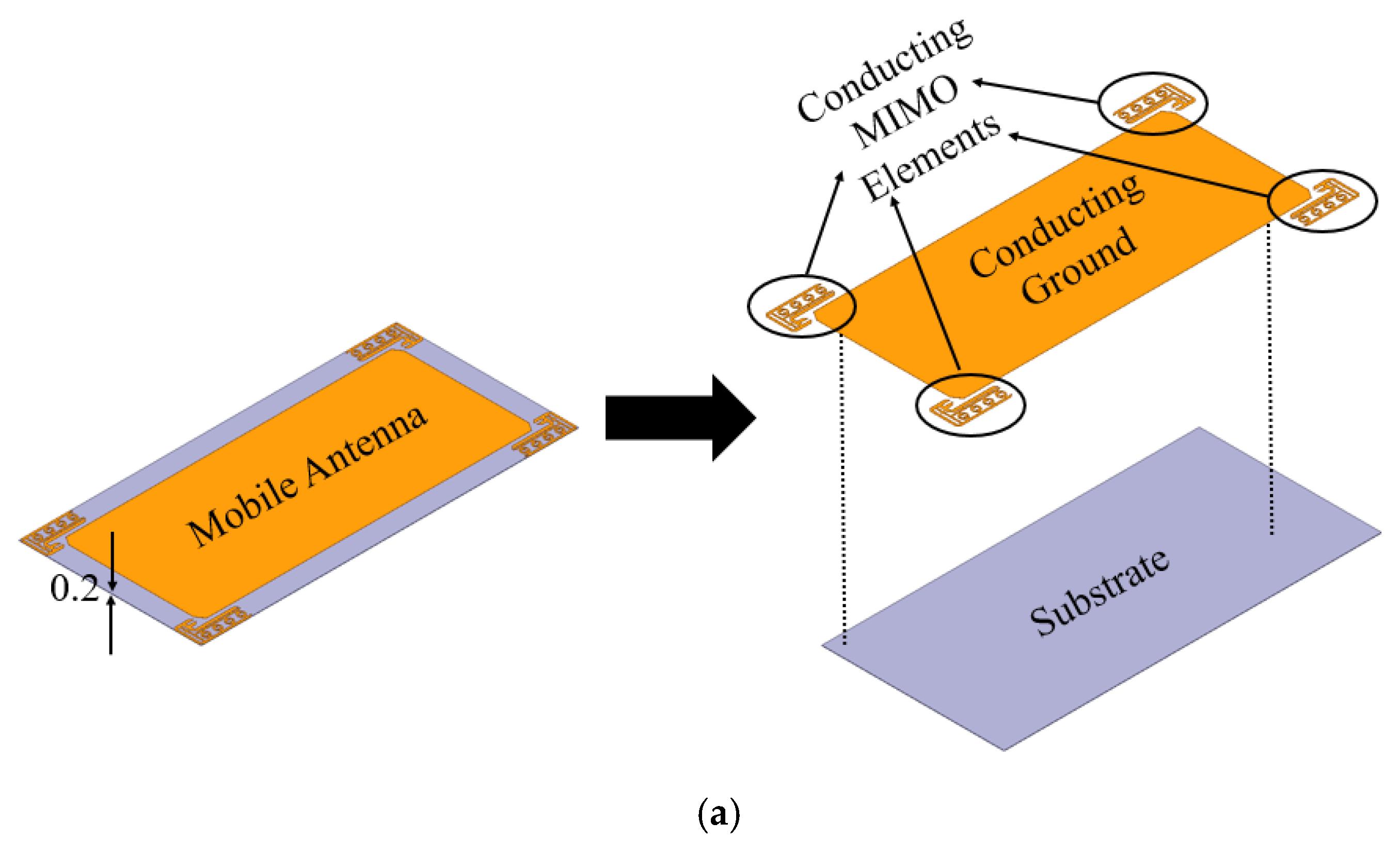
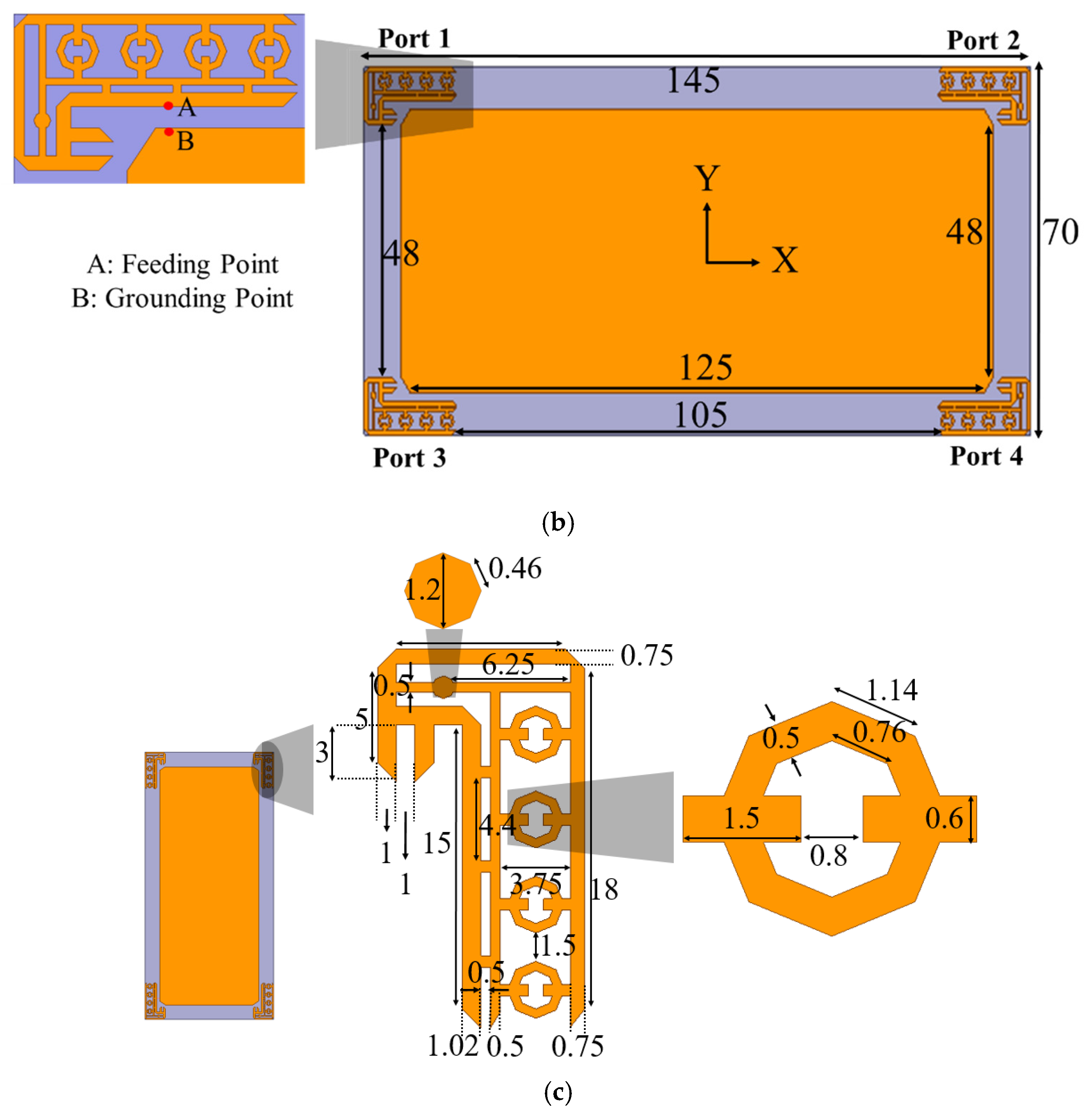
  • The antenna is a four-port structure with all the four elements connected to a common ground plane.
  • The antenna operates in the entire sub-6 GHz 5G band (3.3 GHz–5 GHz) along with the WLAN band (2.4 GHz and 5 GHz).
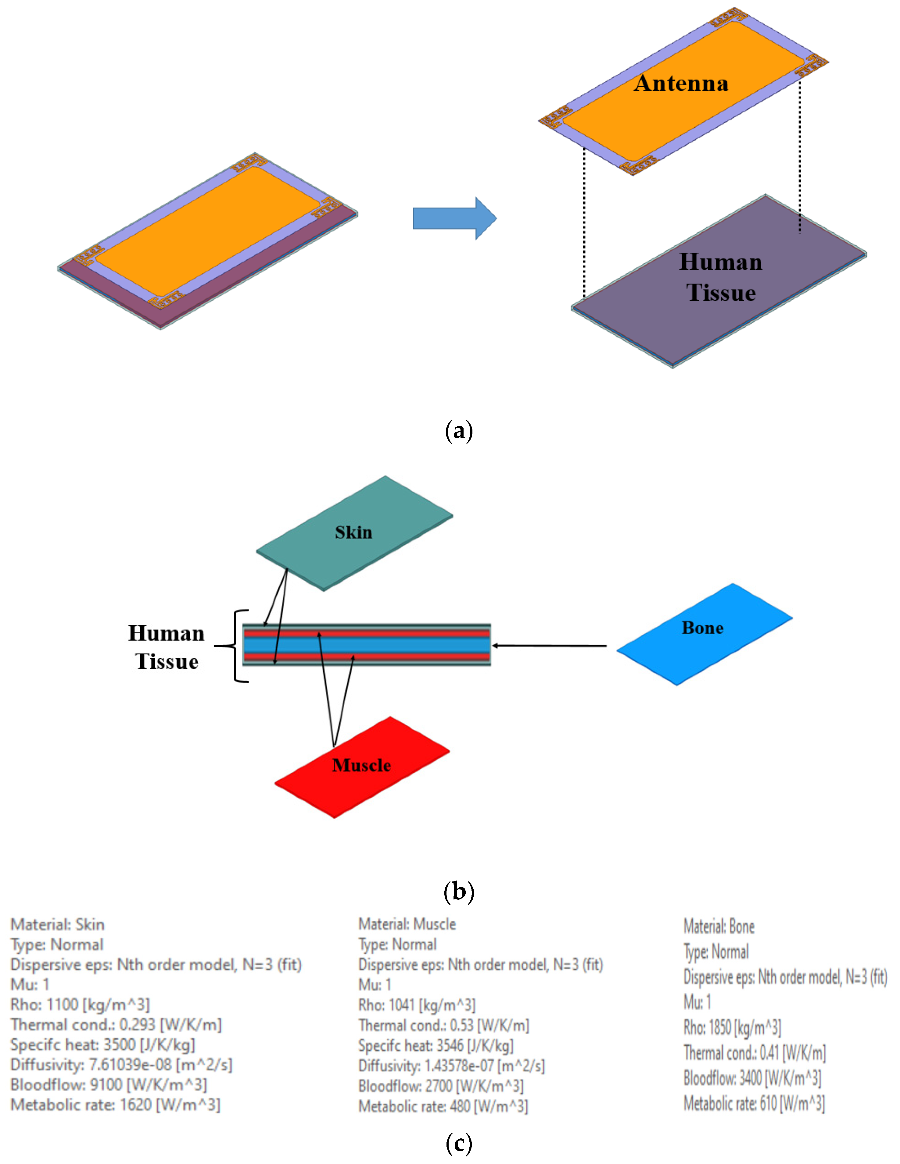
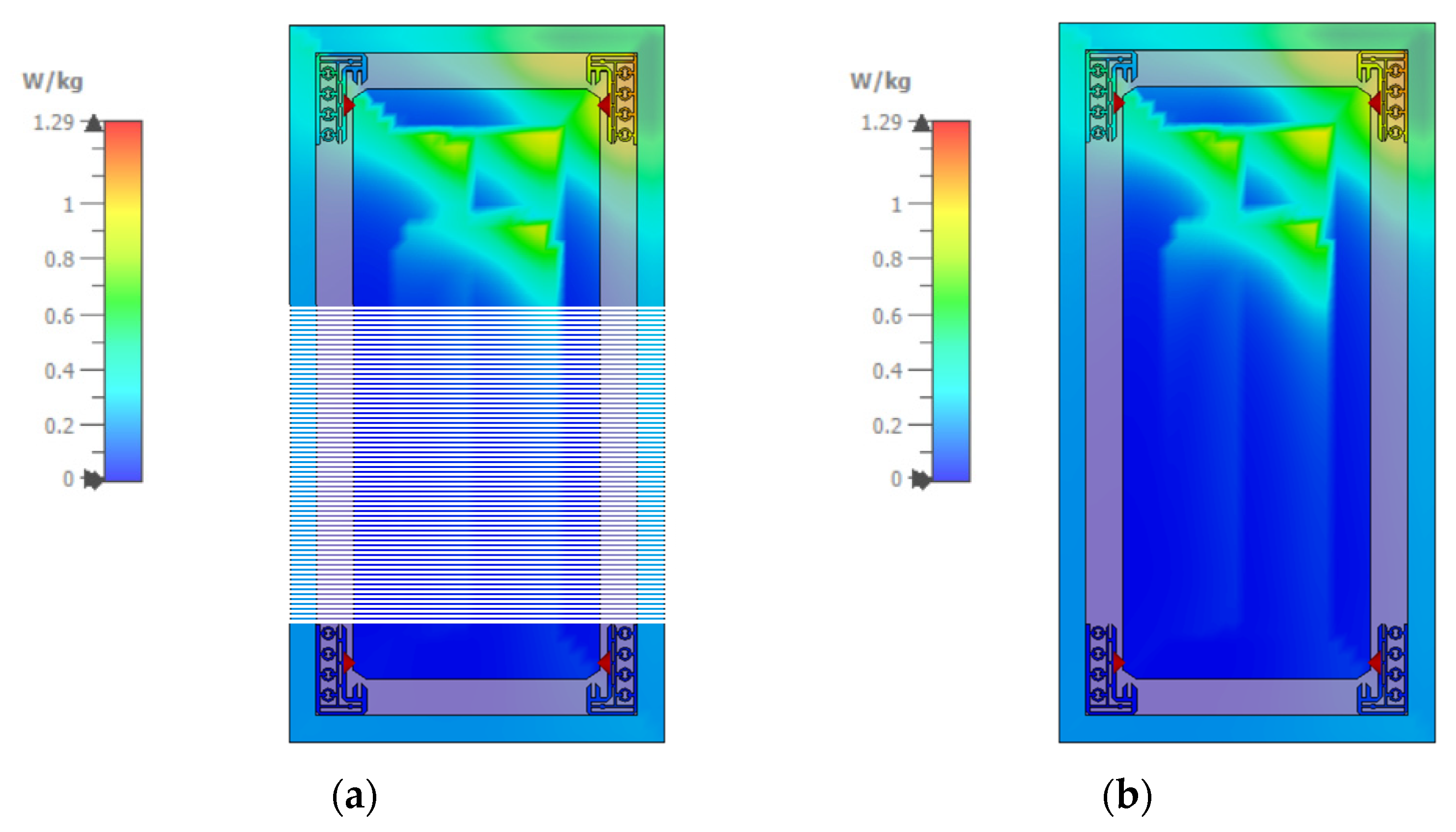
  • SAR analysis is carried out at two resonant peaks (3.5 and 5.1 GHz) in order to ensure the safe usage of the antenna in mobile terminals.
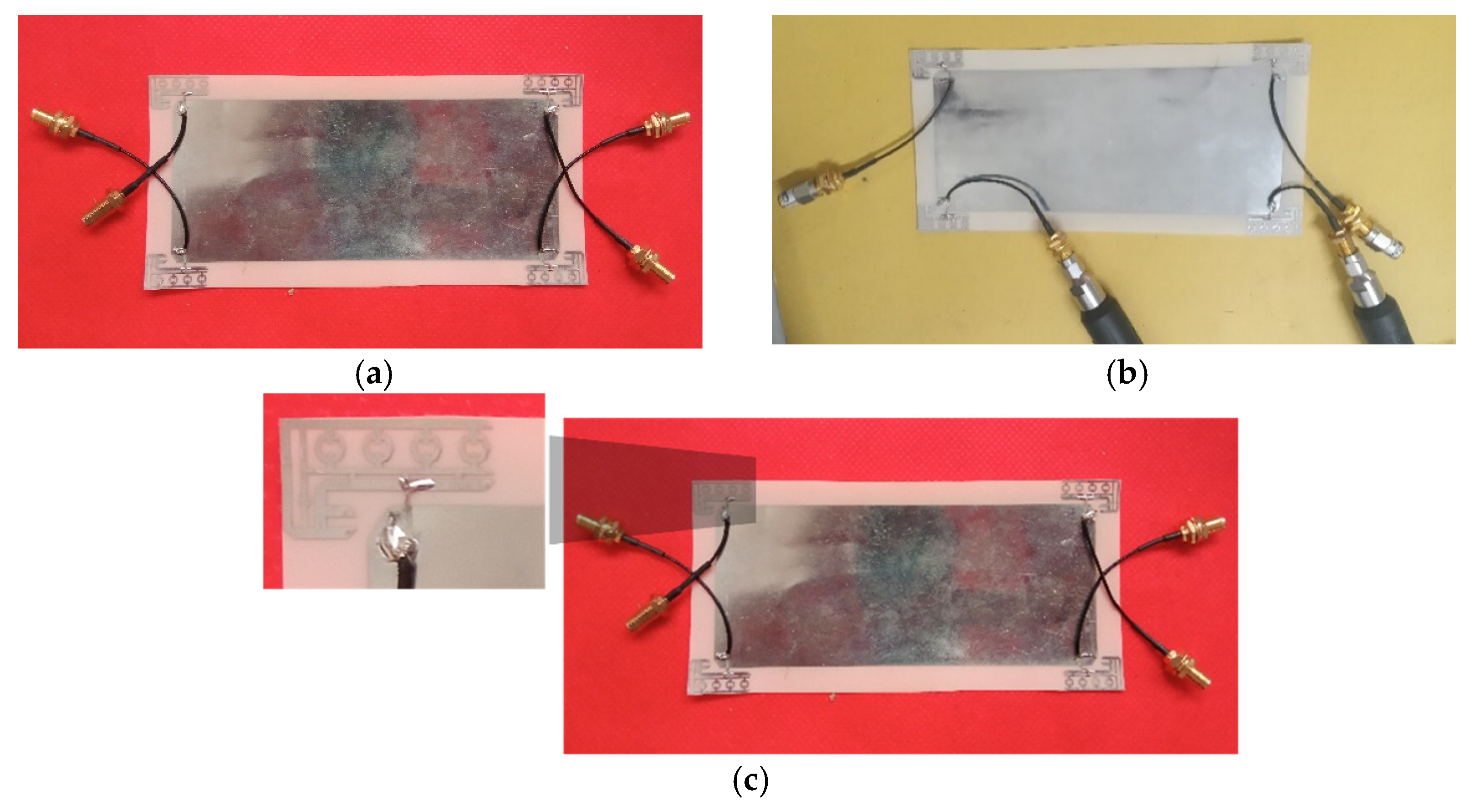
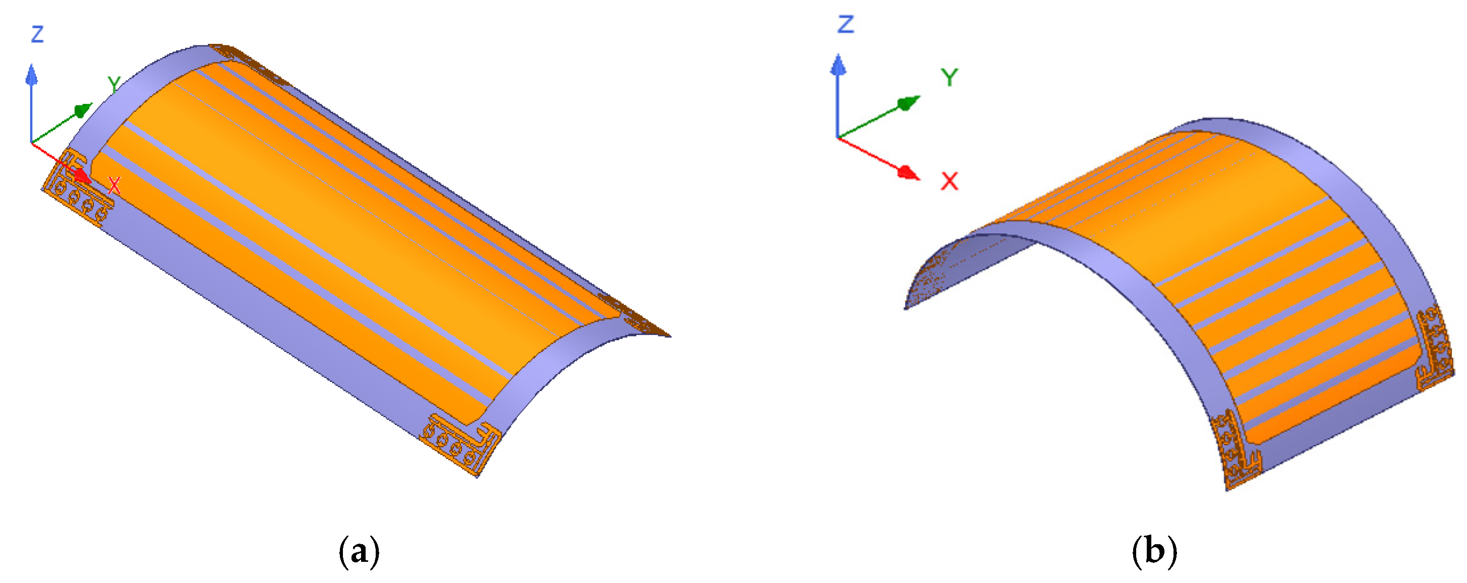
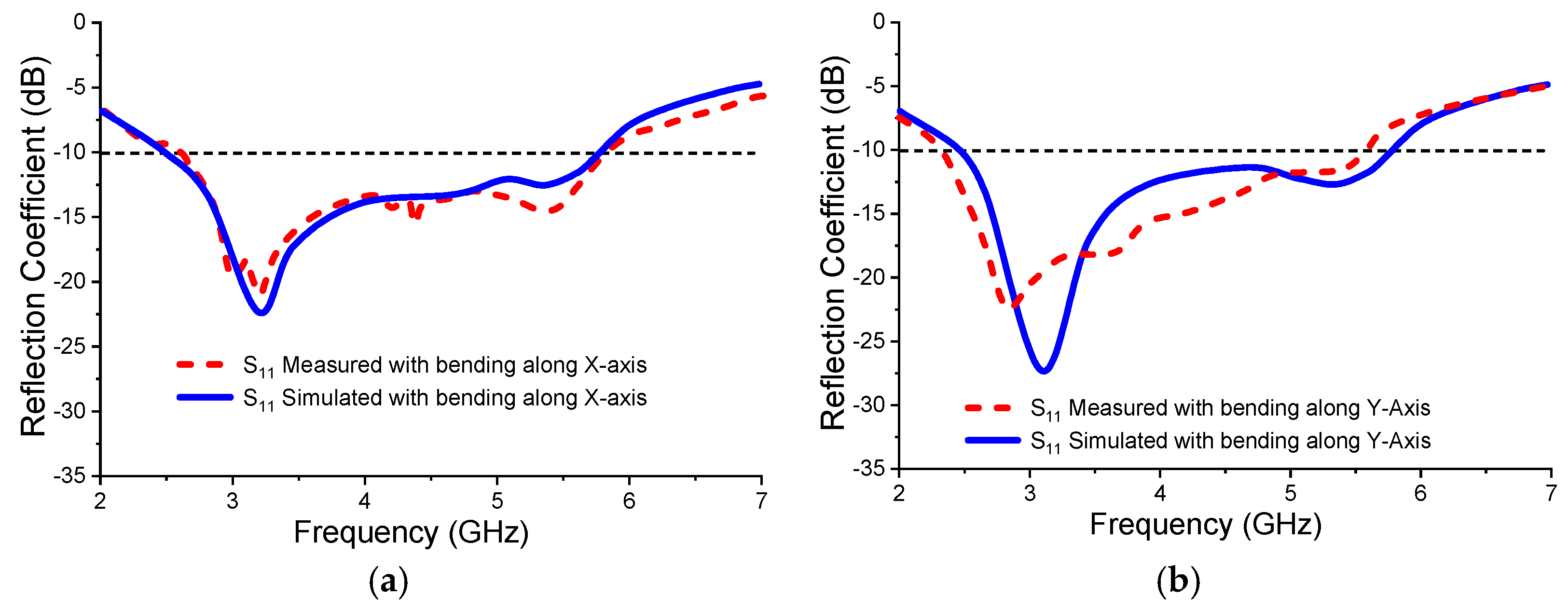
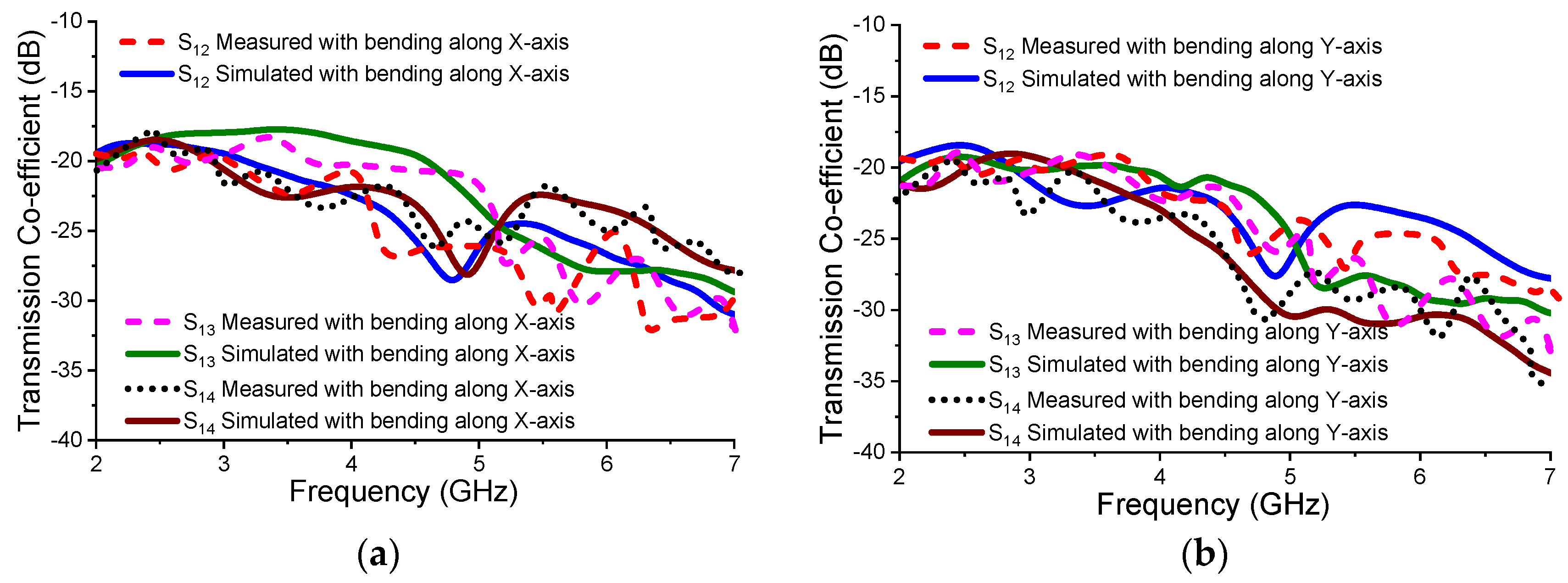
  • Bending analysis is performed, which shows decent performance in terms of MIMO diversity, transmission, and scattering parameters that guarantee the practical usage of the antenna for slim and foldable smartphone devices.
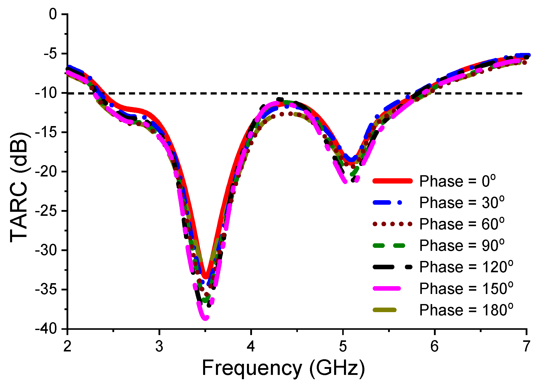
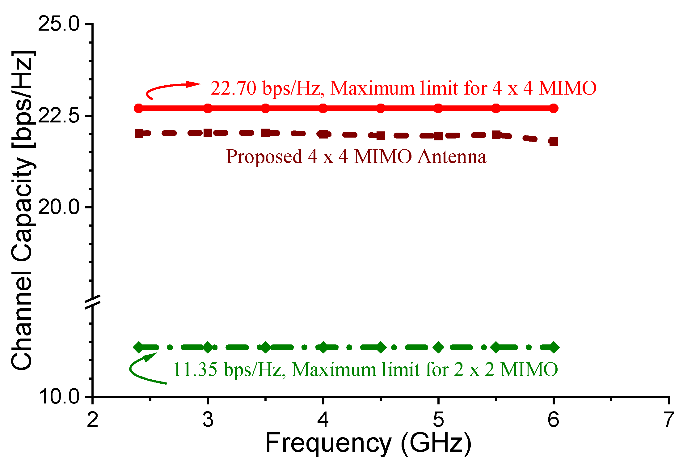
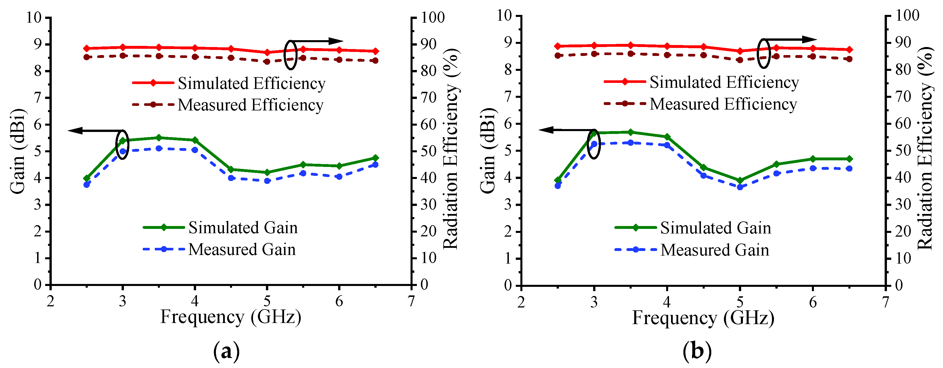
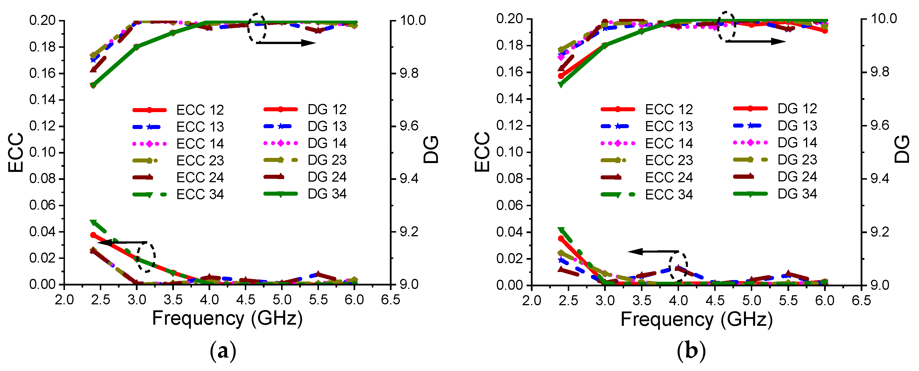
  • The antenna has demonstrated high gain (>4 dBi), high inter-elemental isolation (>17.5 dB), and reasonable efficiency (85%) with all the diversity parameters such as ECC, DG, TARC, MEG, and channel capacity meeting the requirements of MIMO antennas. Scattering, transmission, and MIMO parameters matched well under normal as well as bending conditions.
This paper illustrates a planar four-port and four-element flexible MIMO antenna resonating at WLAN and sub-6 GHz 5G bands. Having features such as flexibility, a bi/omnidirectional radiation pattern, planar structure, wide bandwidth covering Sub-6 GHz and WLAN bands, high inter-elemental isolation, and suitable MIMO diversity parameters under normal and bending conditions makes the proposed antenna appropriate for smartphone applications. Each radiator has a single feeding port connected to the central common radiating plane. The antenna achieves the required isolation as the four antenna elements are positioned at the diagonally opposite corners of the ground plane, thus achieving the required spatial diversity. SAR analysis and the flexibility of the antenna prove the practical usage of the antenna for slim and foldable smartphone devices.

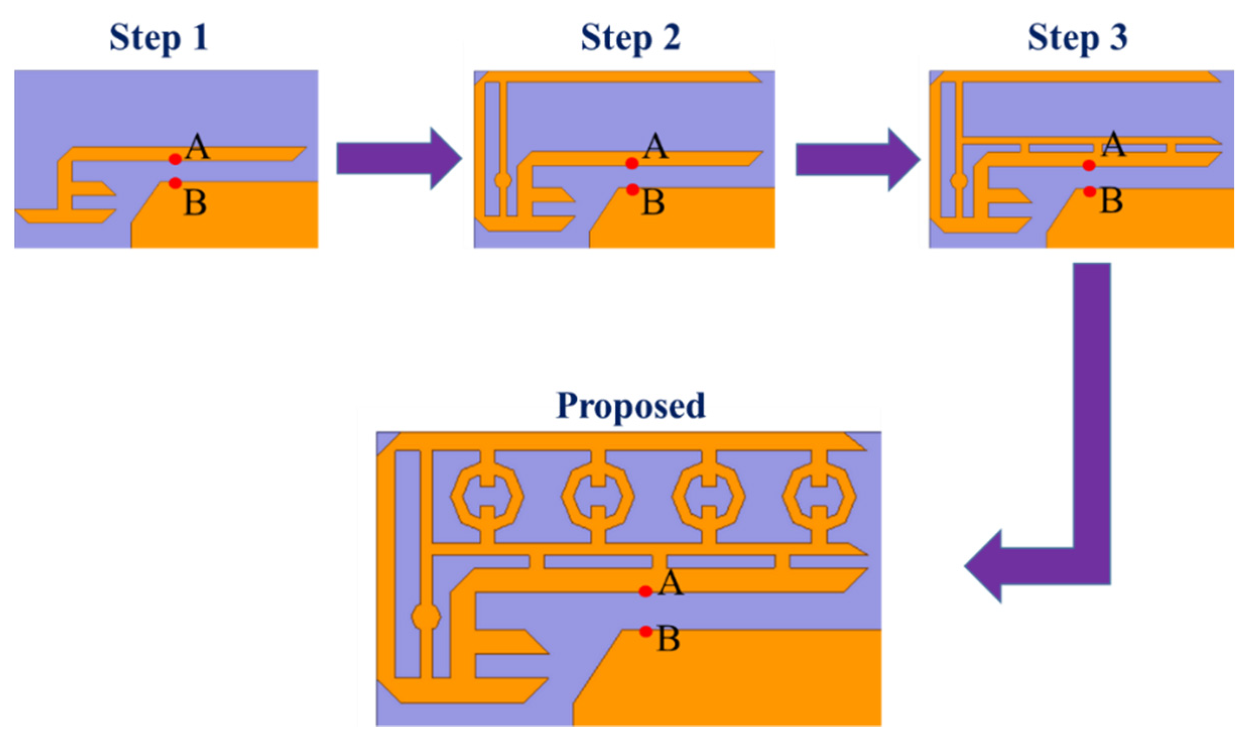
3. Mobile Antenna Design and Geometry

Figure 1a shows the layered view of a flexible four-element MIMO antenna geometry with the common conducting ground at the center. A flexible polyamide substrate (dielectric constant of 3.5 and loss tangent of 0.0027) is used with diagonally placed antenna elements at the corner of a common ground plane. Figure 1b shows the top view where it is observed that the dimensions of the antenna are 145 × 70 × 0.2 mm3. Four conductive antenna elements (diagonally placed) with the common center-ground and fed using a discrete port (A: feeding point and B: grounding point) are all printed on the top side of the substrate.
The detailed view of the single element structure of the antenna is illustrated in Figure 1c, which consists of four octagonal rings embedded between two opposite sides of a T-shaped conductive layer surrounded by inverted angular edge cut L-shaped and E-shaped structures. The inset view of the solid octagonal shape located on a T-shaped branch and four hollow octagonal shapes on the right side of a T-shaped branch is shown. The latter hollow octagonal shapes are connected with two rectangular stubs separated by a distance of 0.8 mm to the vertical side edges. All the edges of the inverted L-shaped strips and E-shaped strip are cut at an angle of 45°. The dimensions are indicated in the figure itself, where the units are in terms of millimeters (mm).
While designing the proposed flexible single-element antenna, a few steps are followed to reach the final design, as shown in Figure 2, and their corresponding reflection coefficient results are shown in Figure 3. Initially, an inner E-shaped strip having angular cuts at the edges (step 1) is adopted. The antenna in this case shows a single band performance at a resonance of 3.8 GHz. In the second step, an additional angular edge cut inverted L-shaped conductive strip along with a vertical strip embedded with a solid octagon is inserted for enhancing the frequency response where dual-band performance is observed; however, the lower band is not in the WLAN/5G regime. Thus, in the third step, a horizontal line is incorporated above the E-shaped strip, which is interfaced with the top edge of the E-shaped strip through three vertical conductive strips. The same leads to improved frequency response; however, the wideband performance is still not achieved. So, in the final stage, four octagonal rings are inserted for achieving bandwidth and reflection coefficient performance to cover the essential WLAN/5G bands. Thus, the final step shows the simulated −10 dB impedance bandwidth spanning from (84.67%) 2.37–5.85 GHz.

4. Results and Discussion

The proposed four-port flexible smartphone MIMO antenna is fabricated and measured. The fabricated antenna is demonstrated in Figure 4. Each element is given a separate feed through Sub Miniature version A (SMA) to UFL connector concerning the common ground. The S parameters and radiation patterns are measured using the Keysight vector network analyzer and shielded anechoic chamber. While measuring the S-parameters, when two antenna elements are considered as an active radiator, the other two antenna elements are terminated with a load impedance of 50 Ω, as shown in Figure 4b. The inset view is illustrated in Figure 4c in order to clearly showcase the fabricated antenna geometry.

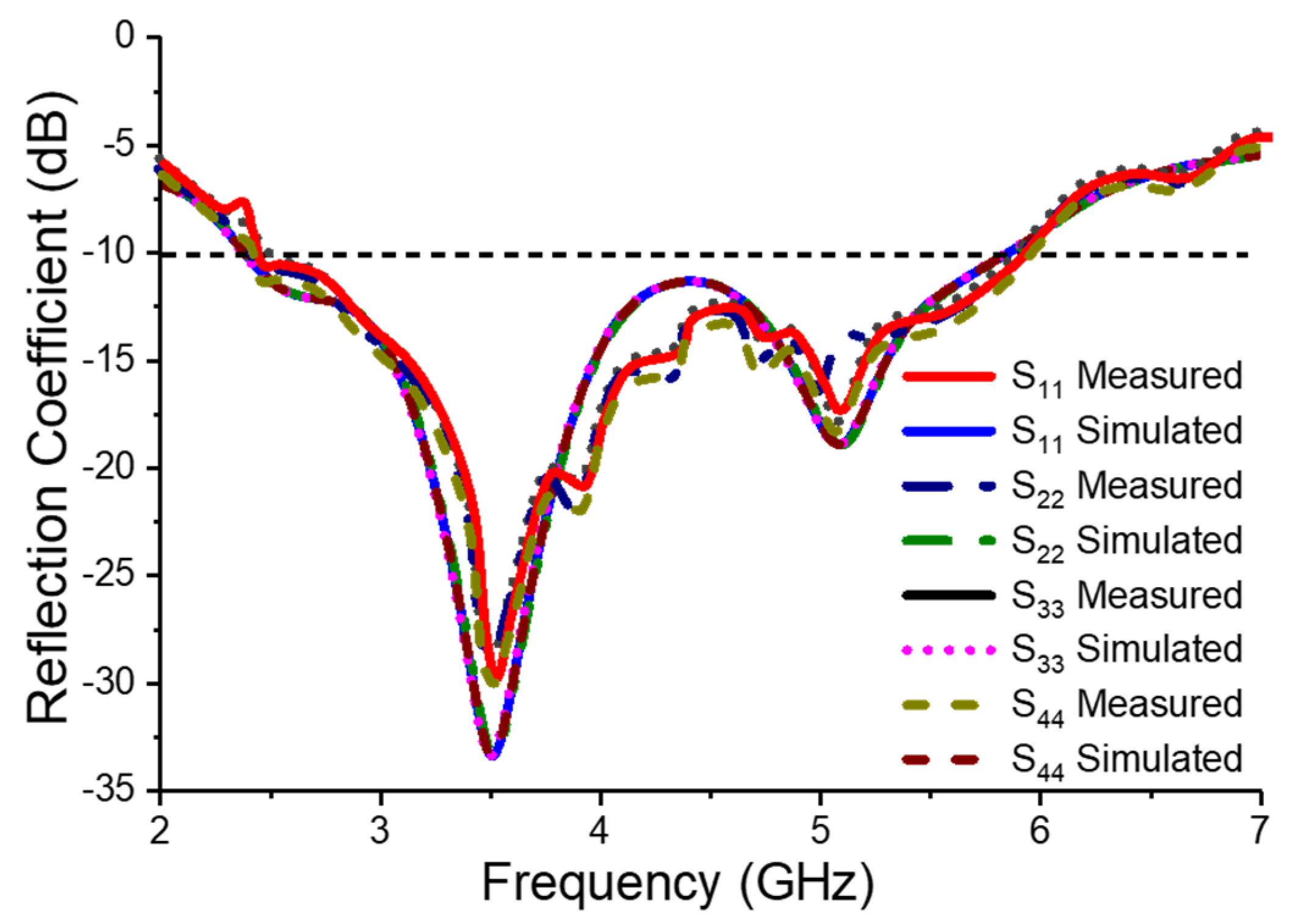
4.1. Reflection Coefficient (dB)

The simulated reflection coefficient results as seen in Figure 5 depicts that all four antenna elements radiate in the frequency band ranging from (84.67%) 2.37–5.85 GHz. The measured reflection coefficient results illustrate that all four antenna elements radiate in the frequency band ranging from (84.12%) 2.39–5.86 GHz. The measured S parameters agree very well with the simulated ones. The slight disparity may be due to the tolerance in size due to the fabrication process and losses across the UFL to SMA connector.

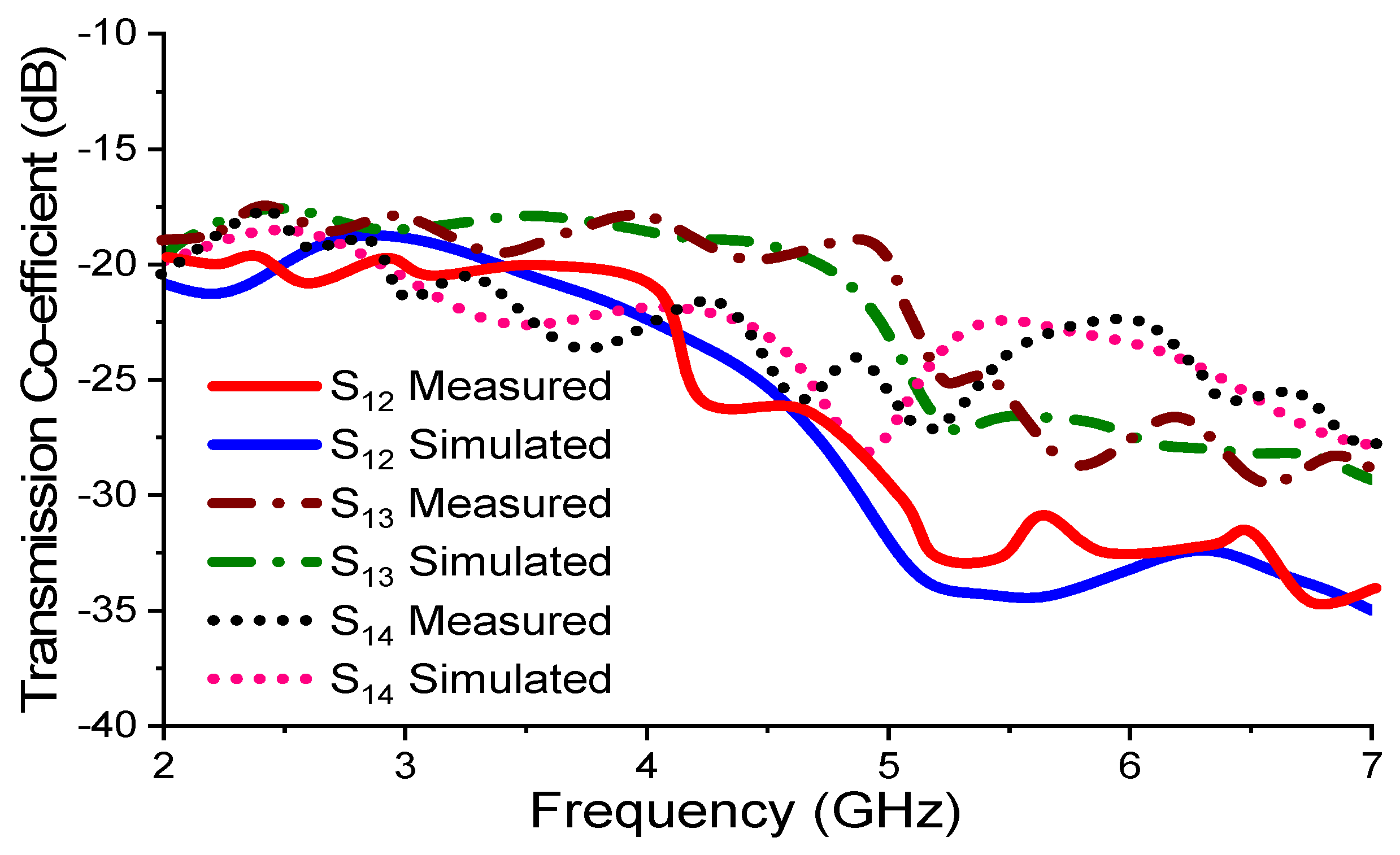
4.2. Transmission Coefficient (dB)

The simulated and measured transmission coefficient (Sij/Sji) results are illustrated in Figure 6. It is easily seen that the mutual coupling between port 1 and port 3 (S13) exhibits the worst-case mutual coupling of −17.5 dB as they are spaced only 48 mm apart. Further, the antenna elements (port 1 and port 2 (S12)) show the minimum coupling of −18 dB as they are spaced at 145 mm apart. Moreover, all the antenna elements exhibit the worst-case mutual coupling of −17.5 dB, which is acceptable for the independent operation of each antenna element in the desired operating band of interest [12,25,26].

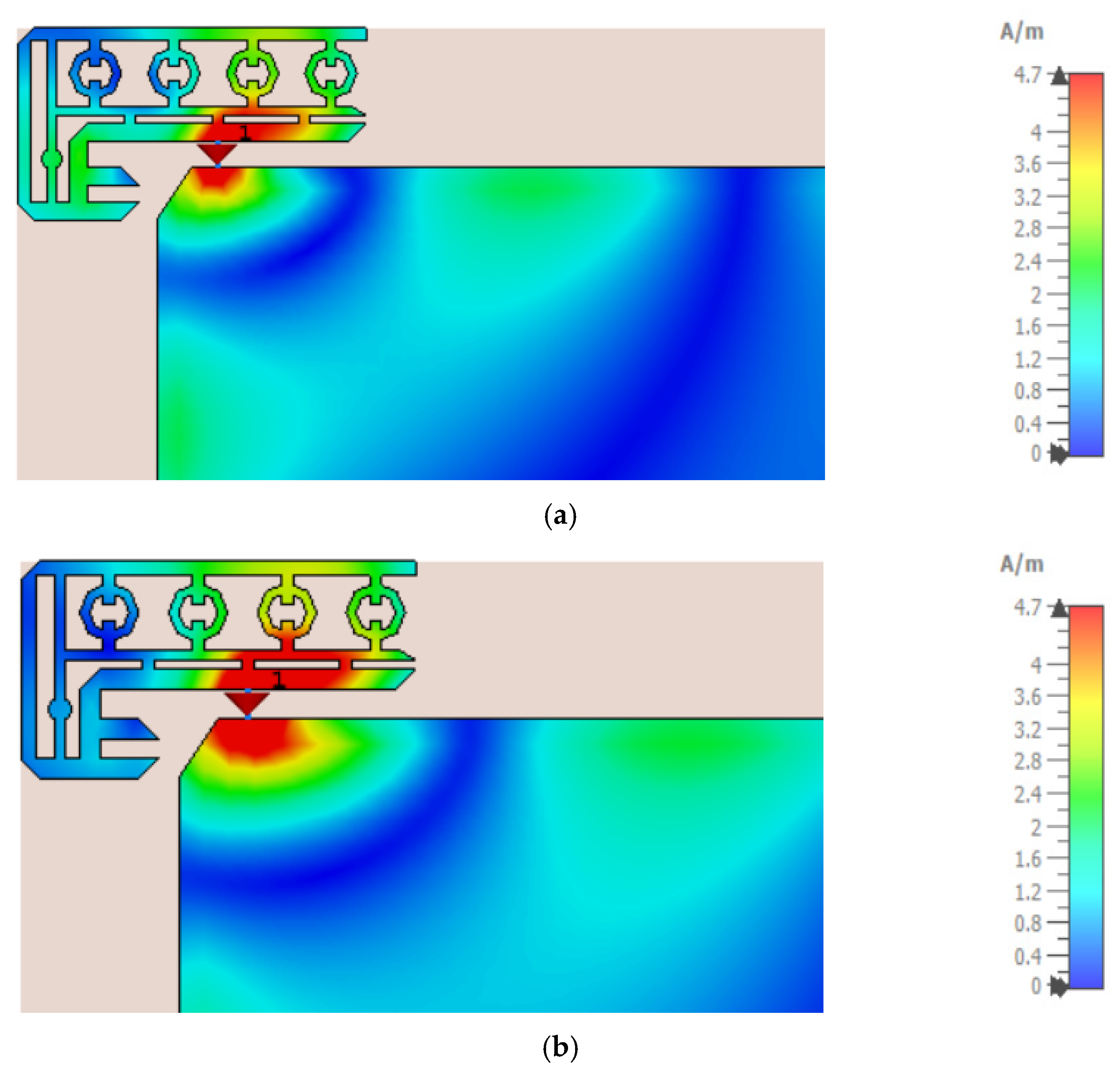
4.3. Surface Current Disctribution (A/m)

To better understand the working mechanism of the proposed mobile MIMO antenna, the surface current distribution at frequencies 3.5 GHz and 5.1 GHz is presented in Figure 7. As observed from Figure 7a, the maximum current flows in the lower part of the radiator, i.e., the E-shaped structure, which results in the generation of resonance at 3.5 GHz. Similarly, from Figure 7b, it is visualized that the current flows through the octagonal ring as well as from the inverted L-shaped strip, which helps in the generation of resonance at 5.1 GHz. So, these two modes are overlapped with the fundamental mode of 3.5 GHz lying in the frequency range of 2.37–5.85 GHz band.

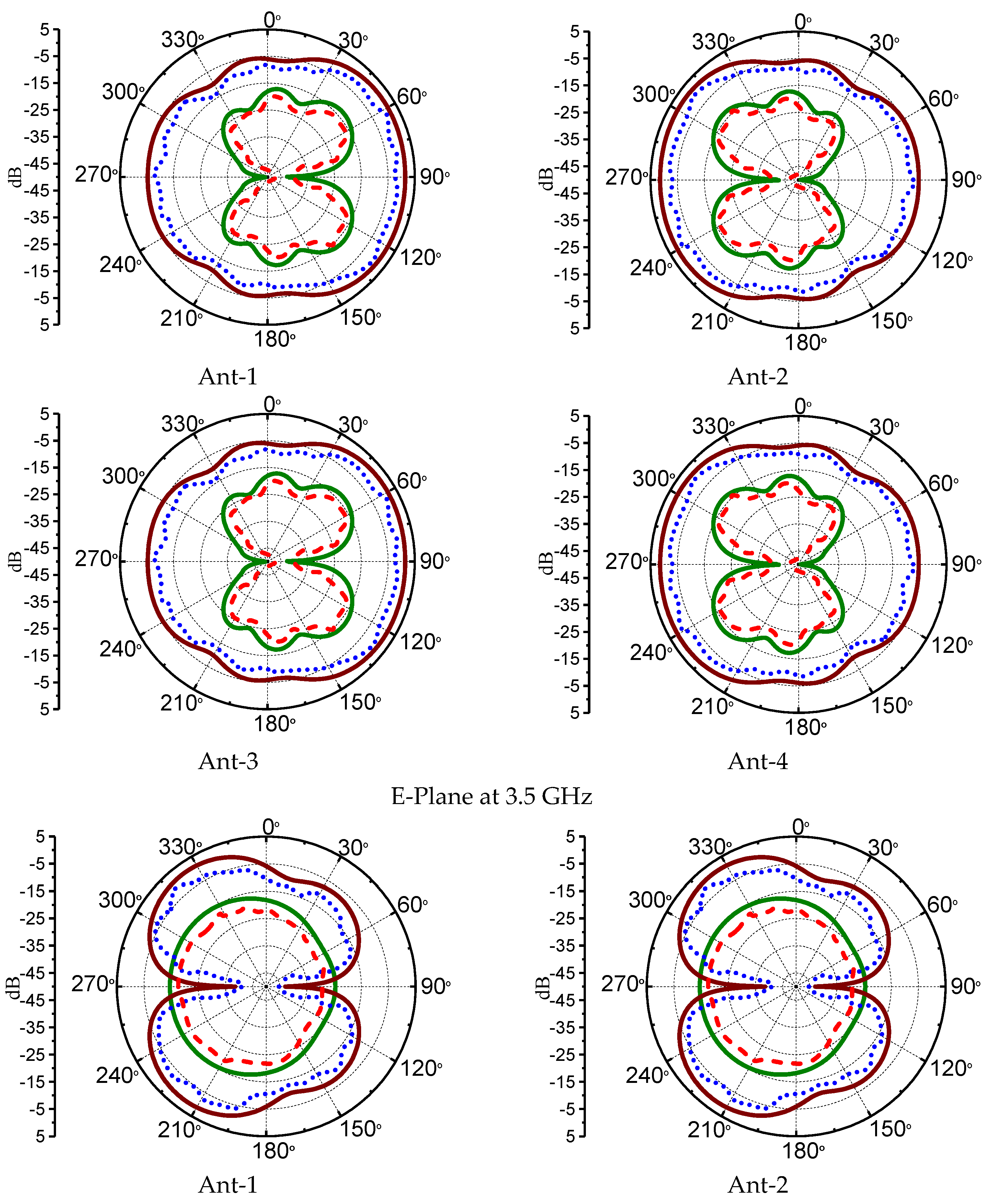
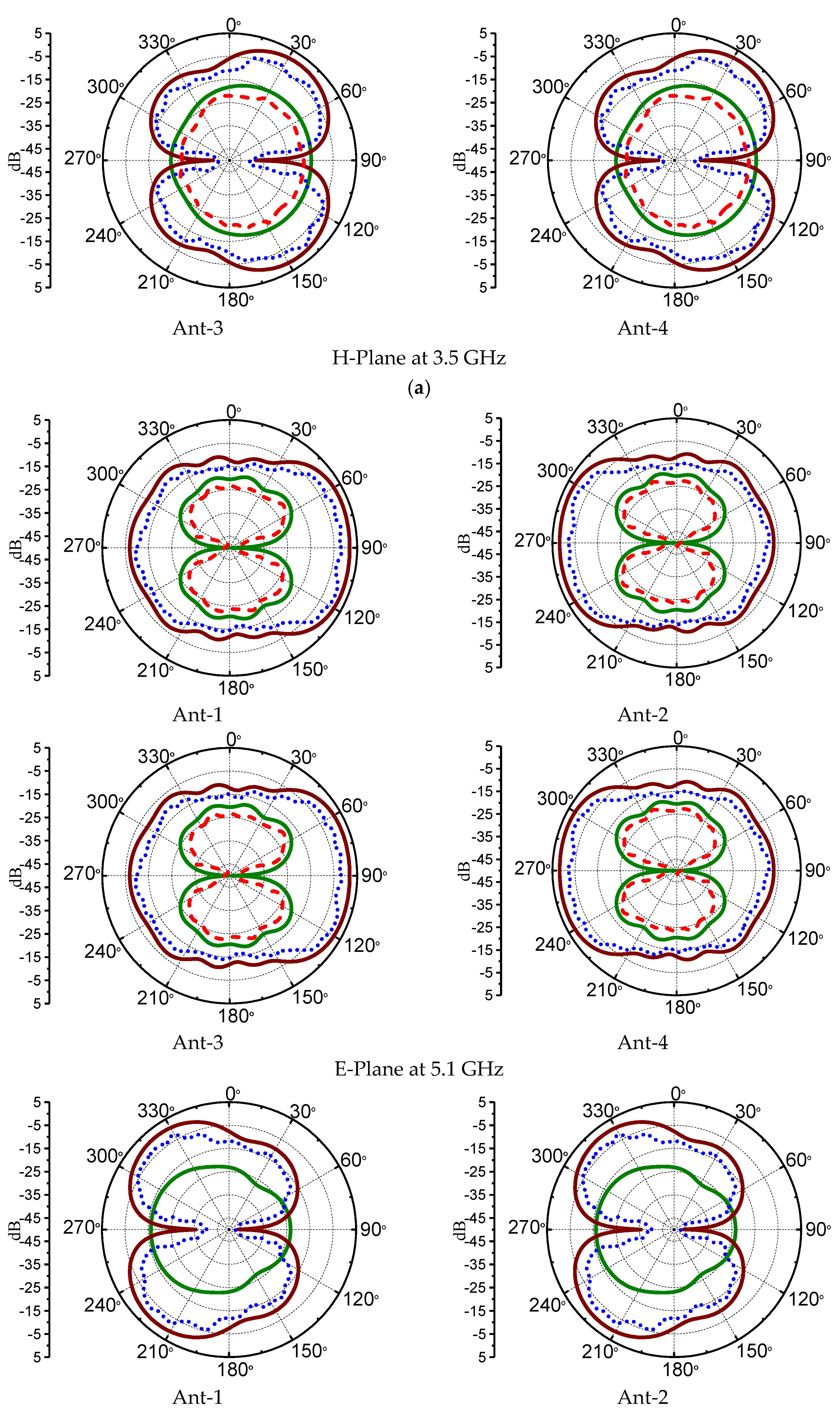
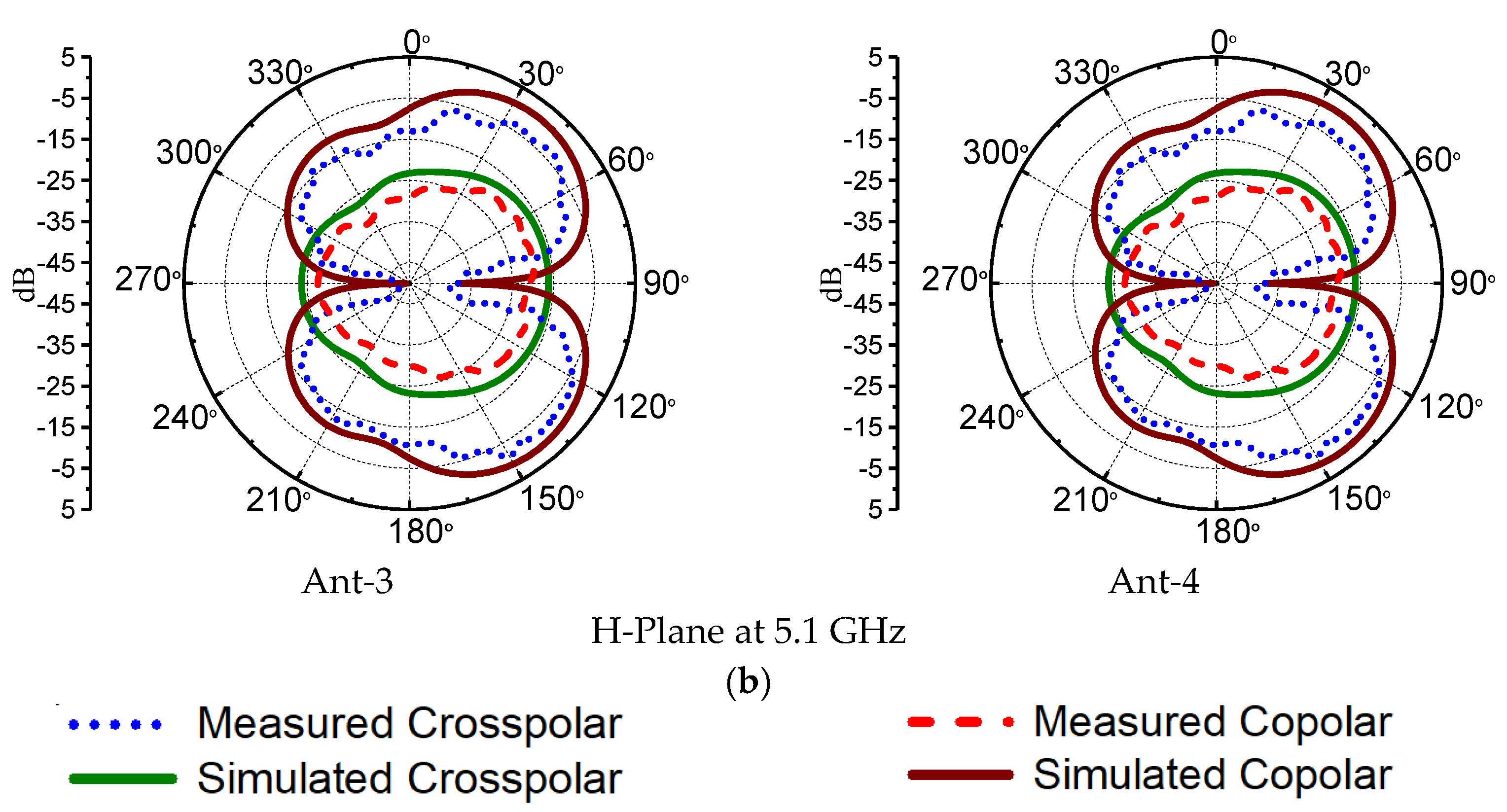
4.4. Radiation Pattern (2D)

To evaluate the radiating performance including far-field patterns of the proposed wideband mobile terminal antenna, the simulated and measured radiation patterns in the E-plane and H-plane at 3.5 GHz and 5.1 GHz are depicted in Figure 8. While measuring the radiation patterns of one port, the other ports are terminated with 50 Ω load impedance. From Figure 8a, it is easily observed that in the E-plane, Ant-1 and Ant-3 as well as Ant-2 and Ant-4 exhibit the same radiation patterns, while the radiation patterns of Ant-2 are a mirror image of Ant-1 and radiation patterns of Ant-4 are a mirror image of Ant-3. Likewise, from Figure 8b, it is noted that in the H-plane the radiation patterns of Ant-1 and Ant-2 as well as Ant-3 and Ant-4 are the same, while the radiation patterns of Ant-4 are a mirror image of Ant-1 and the radiation patterns of Ant-3 are a mirror image of Ant-2. However, in both the E-plane and H-plane, all the antenna elements exhibit the radiation patterns with minimum cross-polar magnitude of −15 dB.

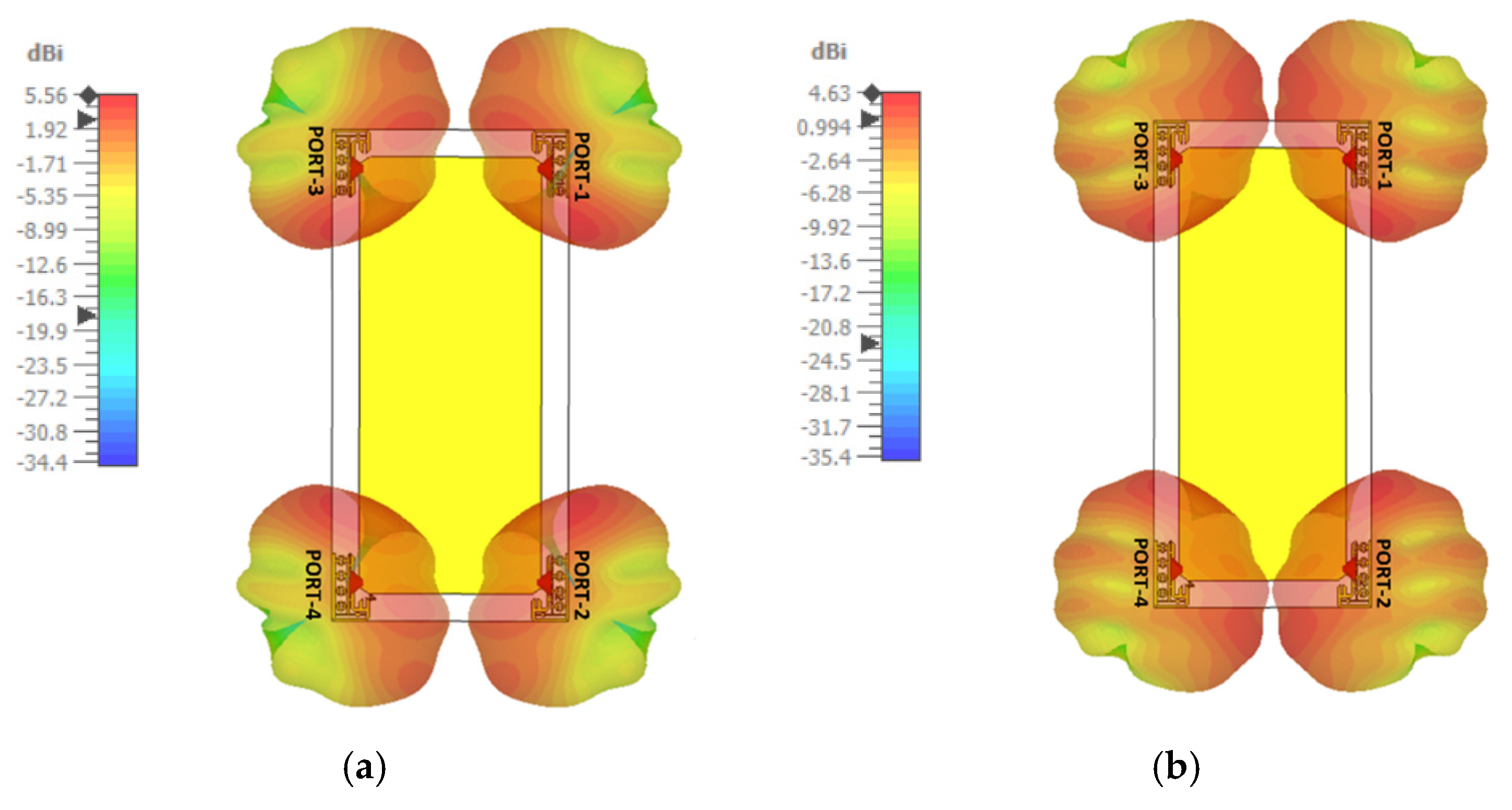
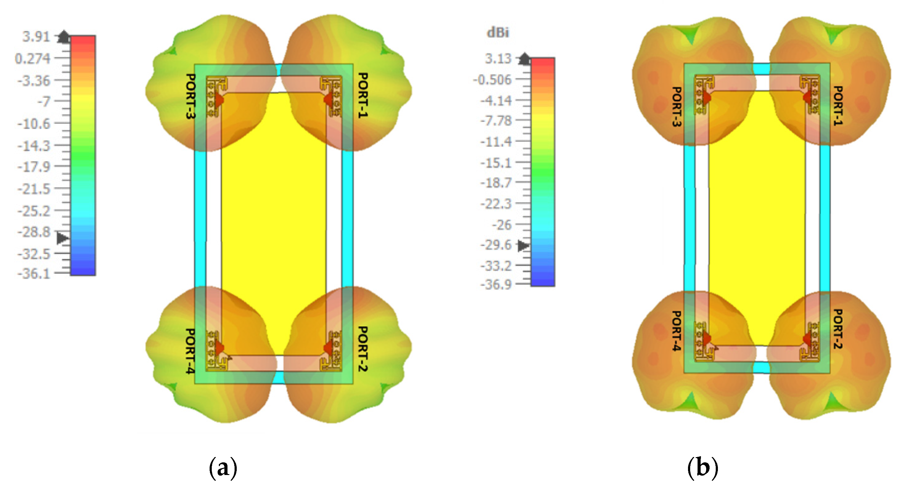
4.5. Radiation Pattern (3D)

The three-dimensional (3D) radiation plots for the total radiated power for all the antenna elements at 3.5 GHz and 5.1 GHz are depicted in Figure 9. The 3D patterns are drawn under the condition when one port is excited while the other ports are terminated with 50 Ω load impedance. As seen from Figure 9 at 3.5 GHz, the maximum gain is achieved for all the ports 1, 2, 3 and 4 with the value of 5.56 dBi, which are placed in the vicinity of the cleared ground region at the corners of the back plane. Likewise, as seen in Figure 9b at 5.1 GHz, the slightly lower gain values around 4.63 dBi are obtained since the size of the antenna elements becomes relatively smaller as compared to the guided wavelength λg.

4.6. Gain and Efficiency

The simulated and measured values of the gain and efficiency of proposed antenna elements are depicted in Figure 10. Due to the similar performances and deployment of antenna elements in the layout of a smartphone antenna, the gain and efficiency of a single antenna element are shown in Figure 10. A minimal difference between simulated and measured values of gain and efficiency is observed, which may be due to the tolerance of the coaxial cable with the SMA connector, 50 Ω load termination impedance, and the impact of hand soldering. However, the simulated gain and measured gain vary from 4 dBi to 5 dBi in the desired frequency range. Likewise, the simulated and measured efficiency is well above 85% throughout the desired operating band of interest.

5. MIMO Diversity Analysis
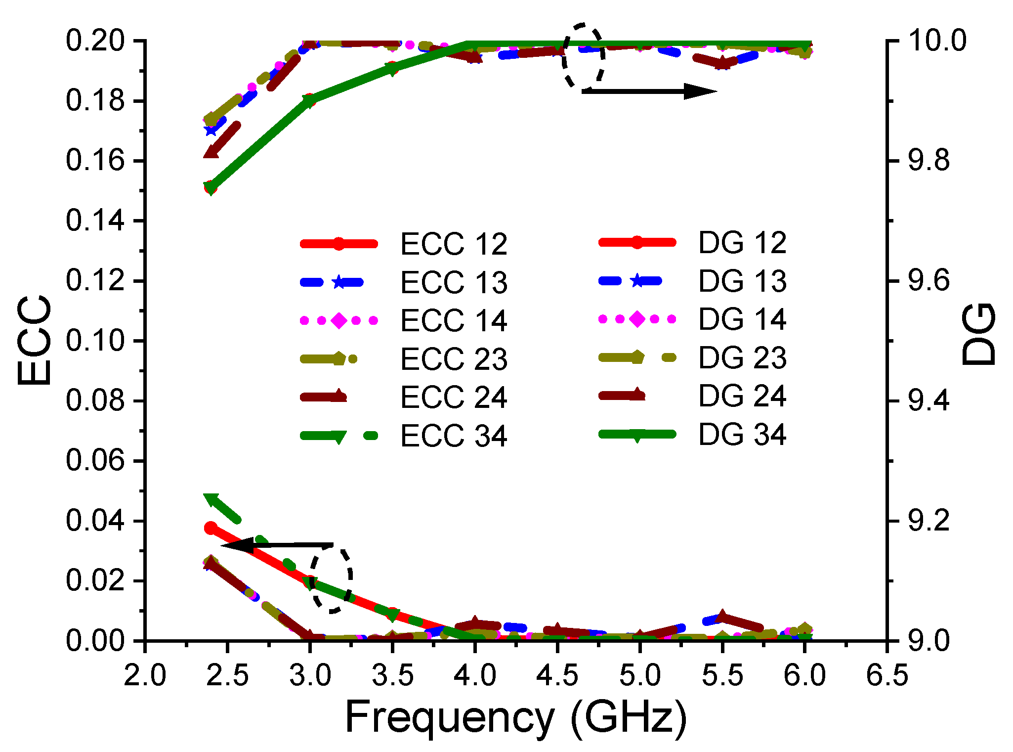
This section investigates the MIMO performance including ECC, DG, TARC, MEG, and MIMO channel capacity for analyzing the performance of the proposed wideband flexible MIMO antenna for smartphone applications.

5.1. ECC and DG

The ECC is a very essential metric to analyze the performance of a smartphone in the presence of a rich scattering environment as the performance of the smartphone is significantly affected by different hand postures. The ECC values should be <0.5 in the presence of a scattering environment to quantify the uncorrelated operation of each antenna element in the multiple antenna system. The ECC is computed from either S-parameters or from 3D far-field radiation patterns. By considering Equation (1), the ECC values are calculated as [26]:
ECC = | [ F i ( θ , φ ) F j ( θ , φ ) ] d Ω 2 | | F i ( θ , φ ) | 2 d Ω | F j ( θ , φ ) | 2 d Ω
where, in Equation (1), F i ( θ , φ ) and F j ( θ , φ ) are the 3D radiation patterns of the antenna when port i is excited and port j is excited, respectively. Ω represents the solid angle, θ , φ represents spherical angles (elevation, azimuth), and * denotes the Hermitian product.
The calculated ECC values for the proposed flexible MIMO antenna are well below 0.05, as depicted in Figure 11.
The diversity gain is calculated by using Equation (2) [26]:
DG = 10 1 | ECC | 2
Figure 11 depicts the value of DG obtained using Equation (2) from far-field radiation patterns. It can be noted that the DG value is greater than 9.8 dB throughout the functioning band. This confirms the good diversity performance of the proposed flexible MIMO antenna.

5.2. TARC

The TARC is a parameter used to validate the performance of an MIMO antenna in a rich multipath fading environment where the phase angle of every path keeps on changing. TARC can be calculated using Equation (3) [26]:
Γ = ( | S i i + S i j e j θ | 2 ) + ( | S j i + S j j e j θ | 2 ) 2
where θ is the input phase angle that is varied from 0° to 180° with an interval of 30°, Sii and Sjj are the reflection coefficients of port one and port two, respectively, and Sij and Sji are the port isolation (dB) between antenna elements.
Figure 12 illustrates the TARC values, which are almost stable throughout the operating bands, which ensures that the proposed four-element mobile MIMO antenna system has achieved high port isolation as well as very stable performance under a multipath fading scattering environment.

5.3. MEG

The MEG values are calculated referring to Equation (4) [26] by considering cross-polarization ratio (XPR) = 0 dB for indoor applications and XPR = 5 dB for outdoor applications under a fading environment.
MEG = π π 0 π [ XPR XPR + 1 G θ ( θ ,   ϕ ) P θ ( θ , ϕ ) + 1 1 + XPR G ϕ ( θ ,   ϕ ) P ϕ ( θ ,   ϕ )
where, in Equation (4), G θ , G ϕ are power gain patterns of antenna elements, and P θ , P ϕ are the available power in vertical and horizontal polarization, respectively. The XPR is the cross-polarization ratio and is expressed as in Equation (5):
XPR = 10 l o g 10 ( P v p a P h p a )
where P v p a and P h p a represent the power received by a vertically polarized antenna and horizontally polarized antenna, respectively. The calculation of MEG signifies the effect of total efficiency, gain, and wireless medium to measure the antenna channel mismatch across the desired operating band of interest. For good diversity performance and power balance, the ratio of MEG of antenna i/MEG of antenna j should be below −3 dB. The calculated MEG values are articulated in Table 1, where it is easily confirmed that all the MEG values are well below −3 dB.

5.4. Channel Capacity

The channel capacity is an essential metric to evaluate MIMO antenna performance in a practical environment and is shown in Figure 13. The channel capacity for the proposed four-port flexible MIMO antenna is calculated using Equation (6), as mentioned in [27,28]. From Figure 13, it is observed that the measured efficiency is around 21.50 bps/Hz under the condition of averaging 10,000 Rayleigh fading with a signal-to-noise ratio (SNR) of 20 dB. It is also noted that the channel capacity of the proposed four-port MIMO antenna is much closer to the ideal channel capacity and is almost 1.89 times larger than the maximum limit for a 2 × 2 MIMO antenna.
C = k { l o g 2 [ d e t ( [ I ] + η S N R k [ H ] [ H ] )   ] }
In Equation (6), I is the identity matrix, SNR denotes the mean SNR, k is the rank of the matrix HH, H is the channel matrix, and HH is the Hermitian Transpose matrix.

6. Bending Analysis

The performance of the proposed four-element flexible MIMO antenna is investigated by varying the operative electrical length under bending conditions. Simulation is carried out in Computer Simulation Technology (CST) Studio Suite®, where the antenna is bent over a cylindrical structure of radius 50 cm, as shown in Figure 14. The antenna validation for flexible applications is performed by plotting the scattering and transmission characteristics as well as gain, efficiency, ECC, and DG [29].

6.1. Reflection Coefficient

Figure 15a,b show the measured and simulated reflection coefficient when the antenna is bent along the X and Y-axis, respectively. It can be easily visualized that an almost identical impedance bandwidth is observed by bending the antenna along the X and Y-axis, respectively, and it operates very well in the desired 5G and WLAN bands.

6.2. Transmission Coefficient

Figure 16a,b show the measured and simulated transmission coefficient when the antenna is bent along the X and Y-axis, respectively. Here, it can be observed that the simulated and measured transmission coefficient is very well above 17.5 dB between all the antenna elements.

6.3. Gain and Efficiency

Figure 17 shows the gain and efficiency of the antenna when the antenna is bent along both the X and Y-axis. It can be observed that there is negligible effect when the antenna is bent along a radius of 50 cm in both the X and Y-axis, and both gain and efficiency are above 4 dBi and 85%, respectively.

6.4. ECC and DG

The ECC and DG under bent conditions are shown in Figure 18. The ECC and DG are almost the same as that in the case of unbent conditions. Here, it is observed that the ECC value is less than 0.05, whereas DG is above 9.8 throughout the desired bands.

7. Impact on User Due to Smartphone Antenna (SAR Analysis)

In this section, the proposed flexible smartphone MIMO antenna is analyzed by interfacing it with the human tissue model. The study on human tissue is essential for assessing its influence on the antenna performance, while it will be interesting to analyze the effect of radiation on a part of the human body close to it.
Figure 19a illustrates the layered view of human tissue underneath the MIMO antenna. The human tissue model simulated for testing with the antenna is shown in Figure 19b, where bone forms the innermost layer covered by muscle, and lastly skin forms the uppermost layer. The characteristics of various layers are depicted in Figure 19c.

7.1. Effect of SAR Analysis on Radiation Pattern (3D)

Figure 20 shows the 3D radiation pattern of the MIMO antenna in the close vicinity of human tissue. As illustrated, good radiation patterns with adequate pattern coverage and gain values are achieved for the MIMO antenna with the human tissue model. Clearly, the human tissue model reduced the antenna characteristics. As seen, the antenna with human tissue in its vicinity still achieves gain values more than 3 dB. The patterns are radiating in different directions, and thus the antenna demonstrated decent spatial diversity at a resonating frequency of 3.5 GHz and 5.1 GHz.

7.2. Effect of SAR on Human Tissue

SAR provides information about the EM absorption by a human body during the transmission and reception of radio frequency signals, which is a grave issue for smartphone systems, and the value of this should be as low as possible. The simulated values of SAR for the proposed MIMO smartphone design in the locality of human tissue model at 3.5 GHz and 5.1 GHz are investigated in Figure 21. The obtained SAR value is lower than the SAR limit in the USA (1.6 W/kg).

8. Performance Comparison of Proposed Antenna

The performance comparison of the proposed four-element mobile MIMO antenna with other mobile MIMO antennas is presented in Table 2.
From the above table, it is observed that the proposed antenna outperforms the other smartphone MIMO antennas in terms of the following criteria:
  • Four-port structure unlike other antennas [9,10,11,12,13,14,15,16] that have two-port configurations.
  • In comparison to four-port antennas [17,18,19,20,21,22,23,24,25], the proposed antenna covers the entire sub-6 GHz 5G band along with the WLAN band (2.37–5.85 GHz) with SAR analysis carried out at two resonant peaks (3.5 and 5.1 GHz).
  • The antennas in [18,20,21,22,23,25] also cover the sub-6 GHz band; however, in [18,22,23,24,25], no SAR analysis is carried out. In [22] as well, the analysis of gain and SAR is missing.
  • The antenna in [21] has a lower bandwidth (3.4–3.6 GHz). Additionally, no bending analysis is carried out for any of the antennas.
  • Flexible structure, high gain, high inter-elemental isolation, and reasonable efficiency with all the diversity parameters such as ECC, DG, TARC, MEG, and channel capacity meeting the requirements of the MIMO antenna make the proposed antenna a good contender for future mobile devices. Scattering, transmission, and MIMO parameters matched well under normal as well as bending conditions.

9. Conclusions

A four-port flexible smartphone antenna with a wideband regime is proposed for sub-6 GHz 5G and WLAN communications. The planar antenna configuration includes four conducting radiators connected to the common ground, which is printed on the flexible substrate. The optimized antenna elements radiate in the range spanning from (84.64%) 2.37–5.85 GHz. The antenna achieves self-isolation greater than 17.5 dB, a decent gain of above 4 dBi, an efficiency of 85%, and bi/omnidirectional radiation patterns with co-cross levels greater than 15 dB. The diversity parameters of MIMO are also analyzed in terms of ECC, TARC, MEG, and channel capacity, where sufficient results meeting the desired limits are achieved. In addition, SAR and bending analyses are also carried out, where safe SAR values are achieved while scattering, transmission, and MIMO parameters match well under normal and bending conditions. The obtained outcomes demonstrate the potential of the proposed flexible MIMO antenna for use in future smart mobile handsets.

Author Contributions

Conceptualization, J.K. and C.-Y.-D.S.; methodology, A.D.; software, J.K.; validation, J.K., C.-Y.-D.S. and A.P.; formal analysis, A.G.A. and A.D.; investigation, J.K. and A.P.; writing—original draft preparation, J.K. and A.D.; writing—review and editing, J.K. and A.D.; visualization, A.G.A.; supervision, C.-Y.-D.S. and A.P.; project administration, J.K.; funding acquisition, A.G.A. All authors have read and agreed to the published version of the manuscript.

Funding

This research received no external funding.

Data Availability Statement

All data are included within the manuscript.

Conflicts of Interest

The authors declare no conflict of interest.

References

  1. Sim, C.-Y.-D.; Chen, H.-D.; Kulkarni, J.; Lo, J.-J.; Hsuan, Y.-C. Recent Designs to Achieving Wideband MIMO Antenna for 5G NR Sub-6GHz Smartphone Applications. In Proceedings of the 2020 International Symposium on Antennas and Propagation (ISAP), Osaka, Japan, 25–28 January 2021; pp. 417–418. [Google Scholar]
  2. Javed, I.; Tang, X.; Shaukat, K.; Sarwar, M.U.; Alam, T.M.; Hameed, I.A.; Saleem, M.A. V2X-Based Mobile Localization in 3D Wireless Sensor Network. Secur. Commun. Netw. 2021, 1–13. [Google Scholar] [CrossRef]
  3. Desai, A.; Upadhyaya, T.; Patel, J.; Patel, R.; Palandoken, M. Flexible CPW fed transparent antenna for WLAN and sub-6 GHz 5G applications. Microw. Opt. Technol. Lett. 2020, 62, 2090–2103. [Google Scholar] [CrossRef]
  4. Ishteyaq, I.; Khalid, M. Multiple input multiple output (MIMO) and fifth generation (5G): An indispensable technology for sub-6 GHz and millimeter wave future generation mobile terminal applications. Int. J. Microw. Wirel. Technol. 2021, 1–17. [Google Scholar] [CrossRef]
  5. Huang, J.; Dong, G.; Cai, Q.; Chen, Z.; Li, L.; Liu, G. Dual-band MIMO antenna for 5G/WLAN mobile terminals. Micromachines 2021, 12, 489. [Google Scholar] [CrossRef]
  6. Kulkarni, J.; Dhabre, S.; Kulkarni, S.; Sim, C.-Y.D.; Gangwar, R.K.; Cengiz, K. Six-Port Symmetrical CPW-Fed MIMO Antenna for Futuristic Smartphone Devices. In Proceeding of the 2021 6th International Conference for Convergence in Technology (I2CT), Maharashtra, India, 2–4 April 2021; pp. 1–5. [Google Scholar]
  7. Srivastava, K.; Kumar, S.; Kanaujia, B.K.; Dwari, S. Design and packaging of ultra-wideband multiple input-multiple-output/ diversity antenna for wireless applications. Int. J. RF Microw. Comput. Aided Eng. 2020, 30, e22357. [Google Scholar] [CrossRef]
  8. Jha, K.R.; Jibran, Z.A.P.; Singh, C.; Sharma, S.K. 4-Port MIMO Antenna Using Common Radiator on a Flexible Substrate for Sub-1GHz, Sub-6GHz 5G NR, and Wi-Fi 6 Applications. IEEE Open J. Antennas Propag. 2021, 2, 689–700. [Google Scholar] [CrossRef]
  9. Huang, D.; Zhengwei, D.; Wang, Y. Eight-band antenna for full-screen metal frame LTE mobile phones. IEEE Trans. Antennas Propag. 2018, 67, 1527–1534. [Google Scholar] [CrossRef]
  10. Hussain, R.; Alreshaid, A.T.; Podilchak, S.K.; Sharawi, M.S. Compact 4G MIMO Antenna Integrated with a 5G Array for Current and Future Mobile Handsets. IET Microw. Antennas Propag. 2017, 11, 271–279. [Google Scholar] [CrossRef] [Green Version]
  11. Ren, Y.-J. Ceramic Based Small LTE MIMO Handset Antenna. IEEE Trans. Antennas Propag. 2012, 61, 934–938. [Google Scholar] [CrossRef]
  12. Xu, Z.-Q.; Sun, Y.-T.; Zhou, Q.-Q.; Ban, Y.-L.; Li, Y.-X.; Ang, S.S. Reconfigurable MIMO antenna for integrated-metal-rimmed smartphone applications. IEEE Access 2017, 5, 21223–21228. [Google Scholar] [CrossRef]
  13. Shi, X.; Zhang, M.; Wen, H.; Wang, J. Compact quadruple band MIMO antenna for 5G mobile applications. In Proceedings of the 12th European Conference on Antennas and Propagation (EuCAP 2018), London, UK, 9–13 April 2018; pp. 1–5. [Google Scholar]
  14. Lee, W.W.; Jang, B. A tunable MIMO antenna with dual-port structure for mobile phones. IEEE Access 2019, 7, 34113–34120. [Google Scholar] [CrossRef]
  15. Deng, C.; Xin, L. Wideband MIMO antenna with small ground clearance for mobile terminals. IET Microw. Antennas Propag. 2019, 13, 1419–1426. [Google Scholar] [CrossRef]
  16. Nie, L.Y.; Lin, X.Q.; Qiang, Q.Y.Z.; Zhang, J.; Wang, B. Structure-shared planar UWB MIMO antenna with high isolation for mobile platform. IEEE Trans. Antennas Propag. 2018, 67, 2735–2738. [Google Scholar] [CrossRef]
  17. Ikram, M.; Hussain, R.; Hammi, O.; Sharawi, M.S. An L-shaped 4-element monopole MIMO antenna system with enhanced isolation for mobile applications. Microw. Opt. Technol. Lett. 2016, 58, 2587–2591. [Google Scholar] [CrossRef]
  18. Biswas, A.; Gupta, V.R. Design and development of low-profile MIMO antenna for 5G new radio smartphone applications. Wirel. Pers. Commun. 2020, 111, 1695–1706. [Google Scholar] [CrossRef]
  19. Zhang, Y.-H.; Yang, S.-R.; Ban, Y.-L.; Qiang, Y.-F.; Guo, J.; Yu, Z.-F. Four-feed reconfigurable MIMO antenna for metal-frame smartphone applications. IET Microw. Antennas Propag. 2018, 12, 1477–1482. [Google Scholar] [CrossRef]
  20. Sun, L.; Haigang, F.; Yue, L.; Zhijun, Z. Tightly arranged orthogonal mode antenna for 5G MIMO mobile terminal. Microw. Opt. Technol. Lett. 2018, 60, 1751–1756. [Google Scholar] [CrossRef]
  21. Sun, L.; Haigang, F.; Yue, L.; Zhijun, Z. Compact 5G MIMO mobile phone antennas with tightly arranged orthogonal-mode pairs. IEEE Trans. Antennas Propag. 2018, 66, 6364–6369. [Google Scholar] [CrossRef]
  22. Deng, C.; Di, L.; Xin, L. Tightly arranged four-element MIMO antennas for 5G mobile terminals. IEEE Trans. Antennas Propag. 2019, 67, 6353–6361. [Google Scholar] [CrossRef]
  23. Chattha, H.T. 4-port 2-element MIMO antenna for 5G portable applications. IEEE Access 2019, 7, 96516–96520. [Google Scholar] [CrossRef]
  24. Cheng, Y.; Hui, L.; Sheng, B.Q.; Zhu, L. A compact 4-element MIMO antenna for terminal devices. Microw. Opt. Technol. Lett. 2020, 62, 2930–2937. [Google Scholar] [CrossRef]
  25. Ricardo, G.-V.; Hildeberto, J.-A. Compact UWB uniplanar four-port MIMO antenna array with rejecting band. IEEE Antennas Wirel. Propag. Lett. 2019, 18, 2543–2547. [Google Scholar]
  26. Kumar, A.; Ansari, A.Q.; Kanaujia, B.K.; Kishor, J. A novel ITI-shaped isolation structure placed between two-port CPW-fed dual-band MIMO antenna for high isolation. Int. J. Electron. Commun. AEU 2019, 104, 35–43. [Google Scholar] [CrossRef]
  27. Wen, J.; Liu, B.; Cui, Y.; Hu, W. High-isolation eight-element MIMO array for 5G smartphone applications. IEEE Access 2019, 7, 34104–34112. [Google Scholar]
  28. Saxena, G.; Jain, P.; Awasthi, Y. High diversity gain super-wideband single band-notch MIMO antenna for multiple wireless applications. IET Microw. Antennas Propag. 2020, 14, 109–119. [Google Scholar] [CrossRef]
  29. Desai, A.; Palandoken, M.; Kulkarni, J.; Byun, G.; Nguyen, T.K. Wideband Flexible/Transparent Connected-Ground MIMO Antennas for Sub-6 GHz 5G and WLAN Applications. IEEE Access 2021, 9, 147003–147015. [Google Scholar] [CrossRef]
Figure 1. Four-element MIMO antenna geometry: (a) Layered view; (b) Top view; (c) Inset view of antenna element (all dimensions in mm).
Electronics 10 03031 g001aElectronics 10 03031 g001b
Figure 2. Evolution steps of the proposed mobile MIMO antenna element.
Electronics 10 03031 g002
Figure 3. Reflection coefficient S11 (dB) of evolution steps of mobile MIMO antenna.
Electronics 10 03031 g003
Figure 4. Fabricated antenna geometry of 4-element mobile MIMO antenna: (a) Top view; (b) Top view with 50 Ω termination; (c) Inset view of antenna element.
Electronics 10 03031 g004
Figure 5. Simulated and measured reflection coefficient of 4-element mobile MIMO antenna.
Electronics 10 03031 g005
Figure 6. Simulated and measured transmission coefficient of 4-element mobile MIMO antenna.
Electronics 10 03031 g006
Figure 7. Current distribution of 4-element mobile MIMO antenna at (a) 3.5 GHz and (b) 5.1 GHz.
Electronics 10 03031 g007
Figure 8. Simulated and measured Co/Cross pol plot of 4-element mobile MIMO antenna at (a) 3.5 GHz and (b) 5.1 GHz.
Electronics 10 03031 g008aElectronics 10 03031 g008bElectronics 10 03031 g008c
Figure 9. Simulated 3D radiation pattern at (a) 3.5 GHz (b) 5.1 GHz.
Electronics 10 03031 g009
Figure 10. Gain and efficiency of 4-element mobile MIMO antenna.
Electronics 10 03031 g010
Figure 11. ECC and DG of 4-element mobile MIMO antenna.
Electronics 10 03031 g011
Figure 12. TARC of 4-element mobile MIMO antenna.
Electronics 10 03031 g012
Figure 13. Channel capacity of 4-element mobile MIMO antenna.
Electronics 10 03031 g013
Figure 14. Geometry of bending the antenna along (a) X-axis, (b) Y-axis.
Electronics 10 03031 g014
Figure 15. Measured and simulated reflection coefficient of 4-element mobile MIMO antenna by bending along (a) X-axis, (b) Y-axis.
Electronics 10 03031 g015
Figure 16. Measured and simulated transmission coefficient of 4-element mobile MIMO antenna by bending along (a) X-axis, (b) Y-axis.
Electronics 10 03031 g016
Figure 17. Gain and efficiency of 4-element mobile MIMO antenna by bending along (a) X-axis, (b) Y-axis.
Electronics 10 03031 g017
Figure 18. ECC of 4-element mobile MIMO antenna by bending along (a) X-axis, (b) Y-axis.
Electronics 10 03031 g018
Figure 19. Antenna and human tissue model: (a) Layered view; (b) Layered view of human tissue; (c) Properties of human tissue model.
Electronics 10 03031 g019
Figure 20. SAR at (a) 3.5 GHz, (b) 5.1 GHz.
Electronics 10 03031 g020
Figure 21. SAR investigation at (a) 3.5 GHz, (b) 5.1 GHz.
Electronics 10 03031 g021
Table 1. MEG of the proposed antenna.
Frequency (GHz)MEGAnt-1/2 (dB)MEG Ant-1/3 (dB)MEG Ant-1/4 (dB)MEG Ant-2/3 (dB)MEG Ant-2/4 (dB)MEG Ant-3/4 (dB)
3.5−3.01−3.01−3.01−3.01−3.01−3.01
5.1−3.01−3.01−3.01−3.01−3.01−3.01
Table 2. Performance comparison of the proposed antenna.
RefYearSize (mm3)FlexibleNo. of PortsFrequency Band (GHz)Gain
(dBi)
Efficiency (%)IsolationECC
[9]2018142 × 79 × 7.5No1(698–960 MHz) and
(1.710–2.690 GHz)
--42----
[10]201760 × 100 × 0.965No21.870–2.530 GHz
28 GHz
4, 87514~0.18
[11]2012110 × 45 × 5No2698 –960 and 1.710–2.690 GHz0–5/2–720–70/4010~0.4/0.03
[12]2017145 × 72 × 0.8No2824–960 MHz,
1.710–2.690 GHz
−0.32–1.4 i/1.6–4.859–72170.02/0.4
[13]2018136 × 68 × 6No23.5–3.9 GHz, 2.3–2.5 GHz, 3.3–3.5 GHz
and 4.25–4.45 GHz
--5010~0.2
[14]201960 × 100 × 1No22.5–3.6 GHz−4.9–−1.9--100.16
[15]201965 × 130 × 1No21710–2690 MHz--60–8019<0.005
[16]2018110 × 120 × 0.508Semi23 to 102.6--38~0.0002
[17]2016100 × 60 × 0.8No42017 and 2265 MHz4.277010~0.18
[18]2020120 × 65 × 1.6No4N77 (3.3–4.2 GHz),
n78 band (3.3–3.8 GHz) and n79 band (4.4–5 GHz),
2,4,4.71--18.8<0.018
[19]2018160 × 85 × 0.8No4824–960 MHz/
1710–2690 MHz)
Reconfigurable
--7010~0.2
[20]2018153 × 77 × 1No43.3–3.6 GHz--64.210~0.11
[21]2018150 × 73 × 0.8No43.4–3.6--51–74 20<0.06
[22]2019140 × 70 × 0.8No43400–3600 MHz--5111.6--
[23]201950 × 100 × 4.5No42.7–3.6 GHz380–90−25 dB--
[24]202039 × 30 × 1No45.15–5.85 GHz2.8>7020<0.02
[25]201938.3 × 38.3 × 0.8No43–13.2 GHz0.5–6.372–97170.02
Proposed 70 × 145 × 0.2Yes42.37–5.85 GHz4–5.58517.5<0.05
Publisher’s Note: MDPI stays neutral with regard to jurisdictional claims in published maps and institutional affiliations.

