1. Introduction
Automation progress in the industry has never been faster. It has been 10 years since the idea of “Industry 4.0” was published [
1]. The changes that have taken place since then have completely changed the approach to designing and managing technological processes. Today, protection devices not only protect equipment but also control them and perform diagnostic functions (allow predicting maintenance or errors in the nearby future) [
2]. Instead of a few devices controlling the technological process (classic solutions), with solutions compliant with Industry 4.0, we have one device that can control and secure the process in real time. The coauthor of the article took part in the development of a power plant designed according to Industry 4.0 guidelines. It gave him the opportunity to explore and analyze how Industry 4.0 has an impact (on a large scale) on the structure of a system (which plays a role in control and diagnosis of the entire technological process).
Depending on the technological process, the control system must follow certain requirements, but the main goal of reliability is common for each system, independently of the control standard. Such control can be realized locally (by a local PLC controller) or by a central unit (main PLC controller) or DCS (Distributed control system) depending on the communication structure. Intelligent protection devices can display and store data using the merging unit. The unit can manage whole subsystems and control protection devices which are connected to it or send all data to the main control system (DCS), which is responsible for a technological process in the factory. The crucial thing in the development of Industry 4.0 as it relates to protection devices is the communication protocol that will be used. It has a main impact on how the structure will look, how fast transfer data will be, and the reliability of the entire topology of the network. The impact of different communication topologies is discussed in detail in
Section 2, evaluating its large influence on the reliability.
Many articles have discussed the subject of Industry 4.0, its key elements based on software development, measurements from various sensors and devices as a whole [
3], or its related ideas [
4]. There are also concepts linking the physical (hardware) and virtual elements (software) as part of the integration of the process production [
5]. During the literature review, the authors tried to find guidelines for the interpretation of Industry 4.0 in the power distribution system and power supply. Searching for keywords relating to Industry 4.0, it was found that the definition of Industry 4.0 has not been clearly outlined in all aspects [
6,
7,
8,
9]. In this article, the authors undertake the description of Industry 4.0 interpretation methodology for power supply systems and process control standards in the field of low-voltage switchgear. The authors would like to point out that there are not many publications in the fields discussed in this article.
The paper is organized as follows: in
Section 2, the concept of automation in low-voltage switchyards according to Industry 4.0 is proposed. The structure of modern protection and control systems in low-voltage switchgear is presented in
Section 3.
Section 4 contains an analysis of the reliability of control protection systems, and
Section 5 outlines the maintenance and work environment for the proposed solutions.
Section 6 and
Section 7 deal with the problem of solution compatibility in terms of data acquisition and storage. Newer devices for data collection and diagnostics require a new approach to designing modern data management systems. Dedicated control systems are based on local servers in cases where the sensitivity of data and security are at the highest level. However, for global data access, the solutions offered by multichord cloud systems allow global data access.
Section 8 describes the results obtained from local structures built in laboratories and from testing facilities of Industry 4.0 automation. Conclusions and the usability of the Industry 4.0 concepts are analyzed in
Section 9.
2. Automation in Low-Voltage Switchyards According to Industry 4.0 Standard
The evolution of new technological advances in the field of protection, control, and data transfer enables a new approach to designing diagnostic and protection equipment in the field of low voltage. The concept of wire connections between devices has disappeared in favor of digital solutions. Constant access to “online” data allows for ongoing monitoring of devices that was previously impossible [
10]. New developments have contributed to the emergence of new solutions in the field of industrial communication protocols (IEC61850, Profinet) [
11,
12]. Thanks to these results, the functionality of existing solutions has expanded. The expansion of the functionality of security, control, and data transfer devices took place not only at the hardware level, but also at the software level. With such an approach, one should ask whether it is possible to diagnose power devices in a given application, as well as identify the diagnostic functions to implement. Thanks to this approach, the standardization of production solutions at the hardware level simplifies the design of the devices themselves. The level of advancement of diagnostics of power devices is constantly growing and may be increased during the operation of devices by changes in the software, which was not the case in classic solutions at the design stage of a given system. Thanks to the continuous archiving of events, the user can predict potential failures on the basis of collected data. Each failure, on the other hand, provides additional data for analysis, thanks to which it will be possible to avoid further failures in the event of a similar scenario.
As mentioned before, a key aspect of the digitization of security and diagnostic solutions that are part of Industry 4.0 is the data collected for analysis. The different concepts for their replacement are shown in the diagrams below (
Figure 1,
Figure 2 and
Figure 3). The schematic diagrams present a low-voltage two-section switchgear consisting of two feeder bays, a coupling bay with a circuit-breaker, a coupling bay with a disconnector, and an ATS system. During normal operation, each section operates independently of the other; in the event of failure of one of the power sources, the ATS system is switched on and, thus, the circuit breaker in the clutch field is closed.
Each section has a number of loads, including drives controlled by PLC controllers, which are called IEDs (intelligent electronic device). In modern solutions, they play the main role of protection, control, and diagnostics. Depending on the manufacturer, their functionality and the possibilities of exchanging and collecting data vary.
Figure 1 shows direct communication with the supervision system (DCS), from which the supervision over the supplied receiver takes place.
Figure 2 shows the connection to the DCS supervisory system through the main controller (gateway). When creating such concepts, one should take into account the importance of the loads supplied from the LV switchgear for the entire application. In the case of critical loads, redundant solutions should be used to increase the reliability of the system, as shown in
Figure 3. A comparison of the three cases described in section was shown in
Table 1.
3. Structure of Modern Protection and Control Systems in Low-Voltage Switchgear
Modern energy distribution systems in the field of low-voltage switchgear can be divided as follows:
Classic, in which we deal with control and communication systems by wire;
Hybrid, in which we deal with both classic and digital solutions based on industrial communication protocols;
Fully digital, based on industrial communication protocols (IEC61850, PROFINET), in line with the concepts of Industry 4.0.
As a result of this division, both the topology and the protection and control system can take different structures. The biggest challenge is designing hybrid solutions, where two concepts of control, diagnostics, and protection collide. This can contribute to many problems resulting from the reliability of a given application, e.g., due to the lack of continuous monitoring of the condition of devices. The best solution in such cases is to choose one of the solutions (classic or fully digital), where the rules for all facilities powered by these energy distribution systems are standardized. Classic solutions are used less and less, mainly in existing facilities, where the same standard of application operation must be maintained. When dealing with newly designed applications, fully digital solutions are used.
Depending on the function of a given device in the topology of the entire system, various communication structures can be outlined. This is due to the relatively different inertia times of measurements or physical phenomena. For example, thermal changes are classified as slow-changing phenomena [
13], compared to short-circuits [
14], where the response time of the device in the form of a trip signal must be immediate. In this case, the use of advanced industrial protocols such as PROFINET or IEC61850 will not be applicable in these processes (temperature change, remote reading of network parameters, etc.). These protocols are crucial in fast-changing processes such as security, where the speed of switching off a given device is of key importance for the safety of both the technological process itself and the people, control systems, where the signal switching off a given device should be received as quickly as possible by the switching off device, and interlocks, in which fast information about the possibility of switching on a given device or its absence must be delivered with the shortest possible delay.
Therefore, it can be assumed that the following rules apply to the topology used in Industry 4.0. In the feeders and couplings, the main switch or field controller should be equipped with a communication system based on the IEC61850 standard. This feature should also be characteristic of the ATS system. In outgoing bays, where we have a number of different devices protecting and monitoring the condition of both power receivers and switchgear elements, it should be possible to use several devices, depending on the purpose and speed of changes in physical processes. Thus, for PLC protection devices (IEDs), the Profinet protocol has become the standard. For other loads, such as measurements, diagnostics of slow-changing processes is done using the Modbus RTU/TCP protocol [
15].
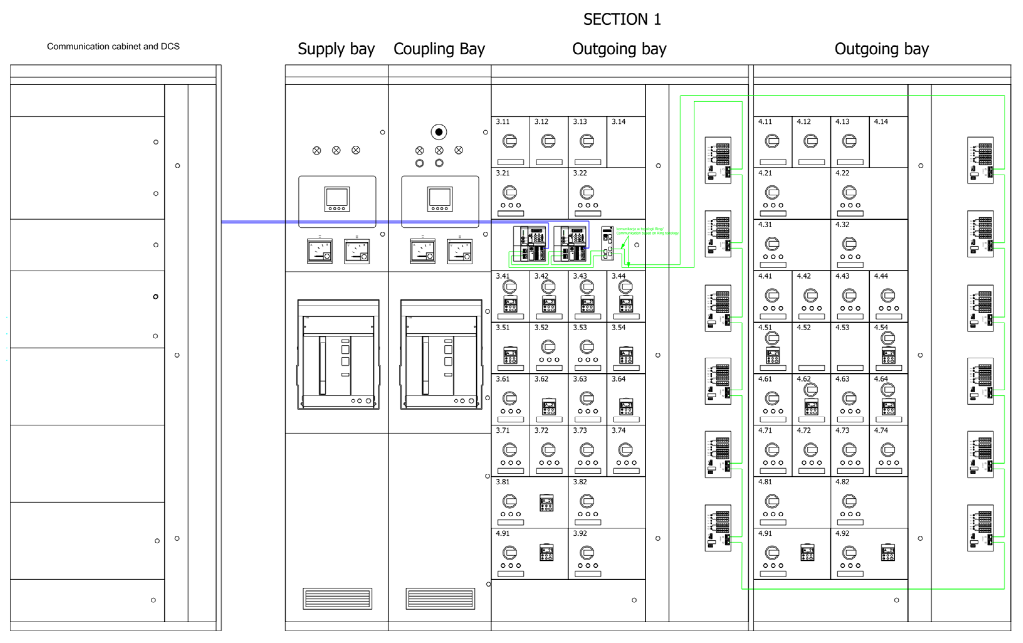
Figure 4 and
Figure 5 show an example of a low-voltage switchgear (two-section, which shows the method of connecting devices based on the ProfNet protocol in a ring structure).
4. Reliability of Control-Protection System
Process reliability and control are key elements of any power distribution system, where a power outage can cause irreparable damage. Therefore, when designing digital switchgears according to Industry 4.0 standard, attention should be paid to the communication structure of the entire process (protocol compliance, transmission speed) [
16,
17], as well as their location in the cabinet supplying key loads. In low-voltage switchgears, we can meet with different load characteristics (direct motor control, reverse or wave operation), as well as a different range of currents from a few amperes to several hundred. Due to the large operating range of each load, problems may arise due to thermal changes, as well as disturbances resulting from high current values. Therefore, in order to increase the prediction of failures, the key elements of the withdrawable modules are monitored in order to minimize their damage and, thus, the failure of the power supply, e.g., drives essential for the safety of the system. This is achieved thanks to thermal sensors that are mounted in the most sensitive places, as shown in
Figure 6.
Another aspect influencing the reliability of the system is the already mentioned communication system. In order to ensure the highest possible reliability of data transmission and to minimize disturbances resulting from large currents that may appear in withdrawable modules, the communication devices should not be located inside the withdrawable modules. Their location in the connection compartments guarantees an increase in the reliability of transmission and, thus, of the entire control system.
Figure 7 shows the ring topologies, in which the main communication modules are located in the discussed connection compartment. A general diagram of this solution was shown in
Section 2 (
Figure 3).
5. Maintenance and Environment
Modern power supply and control systems have changed the approach to the design of drive control systems, as well as their diagnostics [
18]. Thanks to the use of digital solutions and data collection, compared to classic solutions, both the system operator and the manufacturer can monitor the state of the technological process online [
19]. Thanks to these solutions and appropriate modification on the software side, it is possible to create diagnostic and service logics.
Figure 8 and
Figure 9 show two different approaches to diagnosing electric drives. In order to simplify the diagram, one of the many variants of both the control system and the protection functions is shown. This is to show the differences in the approach to implementation and the possibilities of each of the solutions.
Figure 8 shows the power supply and control system, consisting of a fuse switch, a PLC (IED) for protection of the drive, and a contactor as an element that switches the drive, which is equipped with a temperature sensor. This sensor is connected directly to the IED protection. On the right, we can see a typical low-voltage switch-off circuit with withdrawable modules together with the system of signal inputs to the PLC controller and the switching system. The communication process between the PLC and the system is via the communication protocol, according to the topology described in
Section 2 and
Section 3.
Figure 9 shows the classic power and control system. The main current path includes a motor circuit breaker as a protection element for the motor and a contactor that performs a control function. All alarm signals (emergency shutdown, thermal protection), control, and position control are based on wire connections. Communication with the DCS supervision system also takes place via wire connections. In this type of solution, we are not able to control all states of contacts or switches online, and data collection is not possible at the level of the control system itself, which was possible with the solution with a PLC controller. The change in the logic of the entire system involves a redesign of the wire connections and, thus, physical modification of the system. In digital solutions, the same effect can often be obtained by modifying the logic in the device itself, increasing its diagnostic capabilities without interfering with the physical part.
6. Compatibility of Solutions
The energy distribution system in industrial plants is constantly changing. There are continuous modernizations of the existing power control infrastructures in favor of the more modern ones based on digital control solutions. We are talking here about security, communication, and control systems. The dynamically developing market of digital switchgears means that, in order to integrate various systems (both classic and modern), certain compromises are required when creating control and protection systems. In connection with the above, hybrid solutions, where classic and digital solutions are encountered, require a certain compromise, especially in the field of data collection from devices and their diagnostics. In such solutions, problems may arise due to the way data is collected and transferred. Classic solutions send wire signals directly to the DCS (distribution control system). On the other hand, in the digital part of these solutions, information is collected in local PLC controllers, which go through the main PLC controllers in the switchgear, as can be seen in
Figure 10. Therefore, in hybrid solutions, we can deal with different collection structures and data exchange already on the level of one switchgear, even with the choice of one device supplier. As a result, problems with standardization and unification of solutions between different switchboards in a given application may arise.
Another problem that can be encountered in hybrid solutions is the bifunctional ability to control devices. For example, some of the signals can be doubled in the form of fully digital and wire signals, while keeping the same logical functions. One such element may be the control of low-voltage circuit breakers that comply with the IEC61850 standard [
12,
20]. In hybrid solutions, we can control them through digital signals, as well as by introducing on or off the appropriate wire inputs of the signal. In this type of solution, we also have two structures, in which one is constantly monitored and diagnosed in the event of a failure (here, we are talking about digital solutions); in the case of a classic solution, information about damage, e.g., wiring, does not take place.
The above descriptions only refer to selected examples of problems that can be encountered in the case of hybrid solutions. When designing selected structures, you should consider at the design stage what devices will be available (each of them can operate with different structures), and, most importantly, what the nature of the switchgear will be. The choice of fully digital solutions certainly simplifies many diagnostic aspects thanks to continuous monitoring of events in real time [
21]. This allows predicting events in the event of a potential damage to the devices, as well as changing the protection function or adding another to investigate a given problem with the device.
7. Cloud
Control, diagnostic, and security systems are constantly evolving. Newer and newer devices for data collection and diagnostics require a new approach to designing modern process management systems [
22]. In industrial solutions, there are dedicated control systems based on local servers, in cases where the sensitivity of data and security are at the highest level. However, the development of new digital communication standards and a broader look at control, supervision, and diagnostics systems change this approach (from local systems to those with remote access). These solutions are based on remote monitoring and process diagnostics systems in order to better manage and detect undesirable phenomena, as shown in
Figure 11. In this type of solution, we do not have the rights to control the technological process; however, we have the ability to read all system parameters, thanks to which we can increase the predictive capabilities of the system.
This brings new challenges and opportunities. The first is a method of collecting data from hundreds of thousands of devices, whereas the second is obtaining key data that will increase the reliability of a given installation. Compatibility of solutions within different manufacturers is a completely different aspect (even with the use of unified standards of data exchange between devices. This aspect is not discussed in this article.
Diagnostic and monitoring processes of equipment in low-voltage switchgear start with the switch itself. In modern solutions, circuit breakers are equipped with an interface in the IEC61850 standard, which has become the foundation of Industry 4.0 in the power supply sector. In addition to the circuit breaker, key devices support this standard, such as the ATS system. In the distribution part (control systems), we can meet other standards mentioned in the previous section, such as PROFINET or Modbus. Thanks to interfaces such as hubs or gateways, these devices send information from devices to the cloud, which increases their monitoring and diagnostic capabilities (
Figure 11).
An additional benefit that is not directly described in any of the requirements of cloud solutions is the ability to monitor manufactured products around the world. Until now, with classic solutions, monitoring and diagnostic processes of already operating devices were negligible. Only local suppliers could afford to verify their products, where both the product and the customer were well known to them. Cloud solutions have changed the approach to data collection by producers. Global manufacturers, whose products are sold in the millions, access the devices connected to the cloud to create new opportunities for monitoring the condition of their equipment, as well as for improvements as a result of drawing conclusions from unforeseen events in the past.
The implementation of these solutions allows standardizing the equipment already at the design stage to one standard for the entire range of devices through their modularity, which was not previously possible. Changes and modifications that, in classic solutions, required the replacement of the entire apparatus in order to expand their functionality are currently changing at the software level through remote access. Thanks to cloud solutions, the processes of diagnostics, monitoring, and servicing can take place from anywhere in the world, and this makes cloud solutions an innovation on the scale of Industry 4.0 in low-voltage switchgear systems.
The solutions described above are already implemented on the market, thanks to which the access to diagnostic data and monitoring of machines and devices is increasing. One of the basic applications is, e.g., the issue of conducting a periodic service where the user is informed about the performance of these activities, as shown in
Figure 12.
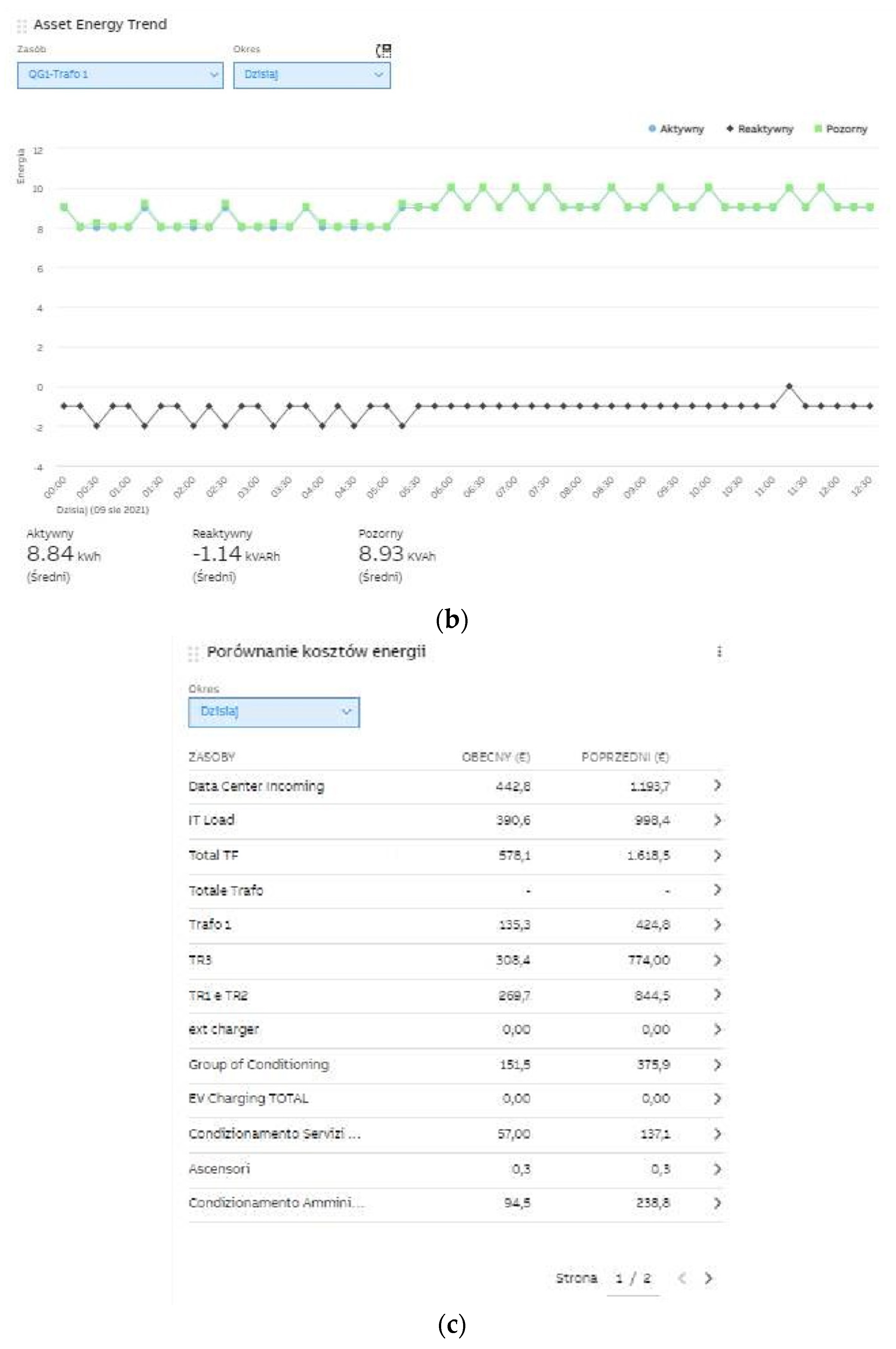
In addition to checking individual parameters of devices and their condition (
Figure 13), we are able to control and monitor the correct operation of the entire switchgear and have access to the history of its operation, as shown in
Figure 14 and
Figure 15 [
23].
8. Results
The application of Industry 4.0 standards in the unit power supply and control systems, with full monitoring of all input/output signals, allows increasing the diagnostic capabilities of the entire structures of low-voltage switchgears. The use of new communication protocols allows us to collect diagnostic data globally, with high accuracy in the long term, in a previously unattainable way. Redundancy in communication circuits and an ordered tree or ring structures increase the reliability of the entire power system, in addition to giving real-time information about potential failures, either on the device side or on the connection between network nodes. The implementation of the above tasks without reproducing them in reality may bring unreliable results. Only the results of the working system based on the new design standard allow assessing the greatest profits resulting from the change to Industry 4.0 standards. The results clearly show that providing two different data transmission sources increases the reliability of the constructed system (in the event of failure of one of them), and new standards such as PROFINET (on the load side) or IEC61850 (on the supply side) increase their reliability and set criteria that these devices must meet. In addition to the fast data transmission, which is required with such a large amount of collected data, it is also necessary to properly analyze and collect them. The annual data balance obtained from an operating unit in the field of vacuum circuit breakers amounts to approximately 16 GB of data. It should be remembered that we are talking about one device that was analyzed. Depending on the size of the industrial plant, the amount of information that must be collected may reach several hundred GB, which must be taken into account when designing the network structure system, as well as the diagnostics and monitoring systems of modern factory low-voltage supply. Such an amount of data analyzed at the “cloud computing” level allows for effective control and prediction of various events depending on the priority of their importance, starting with low-priority alarms, through informing about regular device services, ending with prediction of possible system failure.
9. Conclusions
In the era of a changing world, the change in human habits resulting from the generational change, as well as the development of new technologies, has allowed us to look at power supply and control systems in a new way.
The Industry 4.0 revolution started a decade ago. During this period, the approach to designing power systems in low-voltage switchgears changed. Where high reliability is required, solutions based on PLC controllers are used to increase it. Continuous monitoring of the process in real time improves the diagnostics of devices throughout the production process. Flexibility in the configuration of devices already at the stage of their use is an additional benefit that was impossible in classic solutions. Security settings such as overcurrent protection with any time-dependent characteristic, distance protection, earth fault protection, current direction sensing, and differential transformer protection can all be remotely programmed by the user. Diagnostics of power supply devices, in the long term, is also crucial in the era of event prediction. This requires the collection of a large amount of data to be analyzed. Considering that only one device was tested, in the real production process, there may be several hundred; thus, when automation systems are at the design stage, this amount of data should be considered. The solutions described here undoubtedly have many advantages; however, their implementation is expensive and requires specialist knowledge.
Industry 4.0 solutions are not applicable to all branches of industry, since some automation processes are individual developments, e.g., in the automotive industry; however, they have been found useful in the development of power station supply.
Author Contributions
Conceptualization, Ł.S., J.S., R.D. and M.S.; methodology, Ł.S. and A.S.; software, R.D.; validation, J.S. and M.S.; formal analysis, Ł.S. and J.S.; investigation, R.D.; resources, M.S. and R.D.; data curation, Ł.S., J.S., R.D. and M.S.; writing—original draft preparation, Ł.S. and M.S.; writing—review and editing, Ł.S., J.S., A.S. and M.S.; visualization, Ł.S. and R.D.; supervision M.S. All authors have read and agreed to the published version of the manuscript.
Funding
This research, which was carried out under the theme Institute E-2, was funded by the subsidies on science granted by the Polish Ministry of Science and Higher Education.
Conflicts of Interest
The authors declare no conflict of interest.
References
- Mrugalska, B.; Wyrwicka, M.K. Towards Lean Production in Industry 4.0. Procedia Eng. 2017, 182, 466–473. [Google Scholar] [CrossRef]
- Qin, J.; Liu, Y.; Grosvenor, R. A Categorical Framework of Manufacturing for Industry 4.0 and Beyond. Procedia CIRP 2016, 52, 173–178. [Google Scholar] [CrossRef] [Green Version]
- Alasdair, G. Industry 4.0: The Industrial Internet of Things; Apress: New York, NY, USA, 2016. [Google Scholar]
- Barciński, A. Internet of Things in Industry. Available online: https://automatykaonline.pl/Artykuly/Przemysl-4.0/Internet-Rzeczy-w-przemysle (accessed on 10 March 2017).
- Shafiq, S.I.; Sanin, C.; Szczerbicki, E.; Toro, C. Virtual Engineering Object/Virtual Engineering Process: A specialized form of Cyber Physical System for Industrie 4.0. Procedia Comput. Sci. 2015, 60, 1146–1155. [Google Scholar] [CrossRef] [Green Version]
- Liao, Y.; Deschamps, F.; Loures, E.R.; Ramos, L. Past, present and future of Industry 4.0—A systematic literature review and research agenda proposal. Int. J. Prod. Res. 2017, 55, 3609–3629. [Google Scholar] [CrossRef]
- Lu, Y. Industry 4.0: A survey on technologies, applications and open research issues. J. Ind. Inf. Integr. 2017, 6, 1–10. [Google Scholar] [CrossRef]
- Ślusarczyk, B. Industry 4.0: Are we ready? Pol. J. Manag. Stud. 2018, 17, 232–248. [Google Scholar] [CrossRef]
- Oztemel, E.; Gursev, S. Literature review of Industry 4.0 and related technologies. J. Intell. Manuf. 2020, 31, 127–182. [Google Scholar] [CrossRef]
- Chen, B.; Wan, J.; Shu, L.; Li, P.; Mukherjee, M.; Yin, B. Smart Factory of Industry 4.0: Key Technologies, Application Case, and Challenges. IEEE Access 2018, 6, 6505–6519. [Google Scholar] [CrossRef]
- Dias, A.L.; Sestito, G.S.; Turcato, A.C.; Brandão, D. Panorama, challenges and opportunities in PROFINET protocol research. In Proceedings of the 13th IEEE International Conference on Industry Applications (INDUSCON), São Paulo, Brazil, 12–14 November 2018; pp. 186–193. [Google Scholar]
- Wester, C.; Adamiak, M.; Vico, J. IEC61850 protocol-practical applications in industrial facilities. In Proceedings of the 2011 IEEE Industry Applications Society Annual Meeting, Orlando, FL, USA, 9–13 October 2011; pp. 1–7. [Google Scholar]
- Liu, J.; Li, Y.; Zhao, H. A Temperature Measurement System Based on PT100. In Proceedings of the 2010 International Conference on Electrical and Control Engineering, Wuhan, China, 25–27 June 2010; pp. 296–298. [Google Scholar]
- Li-an, C. Prediction for magnitude of short circuit current in power distribution system based on ANN. In Proceedings of the 2011 International Symposium on Computer Science and Society, Kota Kinabalu, Malaysia, 16–17 July 2011; pp. 130–133. [Google Scholar]
- Kim, C.; Robinson, D. Modbus monitoring for networked control systems of cyber-defensive architecture. In Proceedings of the 2017 Annual IEEE International Systems Conference (SysCon), Montreal, QC, Canada, 24–27 April 2017; pp. 1–6. [Google Scholar]
- Rentschler, M.; Heine, H. The parallel redundancy protocol for industrial IP networks. In Proceedings of the 2013 IEEE International Conference on Industrial Technology (ICIT), Cape Town, South Africa, 25–28 February 2013; pp. 1404–1409. [Google Scholar]
- Kirrmann, H.; Weber, K.; Kleineberg, O.; Weibel, H. HSR: Zero recovery time and low-cost redundancy for Industrial Ethernet (High availability seamless redundancy, IEC 62439-3). In Proceedings of the 2009 IEEE Conference on Emerging Technologies & Factory Automation, Palma de Mallorca, Spain, 22–25 September 2009; pp. 1–4. [Google Scholar]
- Dang, T.; Merieux, C.; Pizel, J.; Deulet, N. On the Road to Industry 4.0: A Fieldbus Architecture to Acquire Specific Smart Instrumentation Data in Existing Industrial Plant for Predictive Maintenance. In Proceedings of the 2018 IEEE 27th International Symposium on Industrial Electronics (ISIE), Cairns, Australia, 13–15 June 2018; pp. 854–859. [Google Scholar]
- Schlechtendahl, J.; Keinert, M.; Kretschmer, F. Making existing production systems Industry 4.0-ready. Prod. Eng. Res. Devel. 2015, 9, 143–148. [Google Scholar] [CrossRef]
- IEC 61850-7-1:2011. Communication Networks and Systems for Power Utility Automation-Part 7-1: Basic Communication Structure—Principles and Models; International Electrotechnical Commission: Geneva, Switzerland, 2011. [Google Scholar]
- Bellagente, P.; Ferrari, P.; Flammini, A.; Rinaldi, S.; Sisinni, E. Enabling PROFINET devices to work in IoT: Characterization and requirements. In Proceedings of the 2016 IEEE International Instrumentation and Measurement Technology Conference, Taipei, Taiwan, 23–26 May 2016; pp. 1–6. [Google Scholar]
- Alcácer, V.; Cruz-Machado, V. Scanning the Industry 4.0: A Literature Review on Technologies for Manufacturing Systems. Eng. Sci. Technol. Int. J. 2019, 22, 899–919. [Google Scholar] [CrossRef]
- Javied, T.; Bakakeu, J.; Gessinger, D.; Franke, J. Strategic energy management in industry 4.0 environment. In Proceedings of the 2018 Annual IEEE International Systems Conference (SysCon), Vancouver, BC, Canada, 23–26 April 2018; pp. 1–4. [Google Scholar]
| Publisher’s Note: MDPI stays neutral with regard to jurisdictional claims in published maps and institutional affiliations. |
© 2021 by the authors. Licensee MDPI, Basel, Switzerland. This article is an open access article distributed under the terms and conditions of the Creative Commons Attribution (CC BY) license (https://creativecommons.org/licenses/by/4.0/).


 ,
, 


