1. Introduction
1.1. Background
According to the report of Cisco, there is an ever-increasing number of devices that are wirelessly connected to the Internet, which will reach approximately 12.3 billion by 2023 [
1]. The performance requirements of the next generation communication system are a peak data rate of 1000 Gbps (gigabits per second) and air latency of less than 100 microseconds (
) [
2]. Furthermore, NR over NTN is being specified in Release 17 [
3]. Hence, this paper aims to stimulate future investigations by the research community on the next generation communication system. One of the research focuses of next-generation communication systems is to achieve 3D seamless coverage, thereby providing efficient, high-quality, low-cost, and global roaming broadband communication services [
4]. 5G relies on the seamless integration of non-terrestrial communication systems (such as unmanned aerial vehicles and ultra-low orbit satellites) with cellular communication systems to achieve this goal [
5]. Satellite communication systems have become the choice to achieve higher capacity, real-time communication, and wider coverage due to their abilities of seamless connectivity and high data rates [
6]. Although the traditional satellite communication systems can cover the globe, it is difficult to meet the increasing demand for users due to their low spectrum utilization and limited satellite capacity.
Compared with Geostationary Earth Orbit (GEO) and Medium Earth Orbit (MEO), Low Earth Orbit (LEO) satellites have many advantages, such as low cost, short delay, small path loss, and so on. There have been many mega-constellations of LEO satellites demonstrated by recent commercial corporations to provide global broadband internet access services, e.g., OneWeb, StarLink, Space X, and HongYan [
7]. At the same time, CubeSats is also being studied which is cost-effective and can be built using commercial off-the-shelf components [
8,
9]. Aiming at ubiquitous connection requirements of users, the next generation communication system puts forward higher requirements for multi-antenna multiple input multiple output (MIMO) technology. However, the small size and light weight make the onboard resource of LEO satellite severely restricted. It is difficult for a multi-antenna device on a single satellite to meet the requirements of MIMO technology for channel isolation, and it is difficult to implement the MIMO technology in a single satellite application scenario. The phased array antenna which can improve the Equivalent Isotropic Radiated Power (EIRP) and the spectral efficiency by building a virtual multi-antenna system is applied to multi-beam satellites. In addition, with the development of Orthogonal Frequency Division Multiplexing (OFDM) and multiplexing diversity technology, packets can be transmitted by coordinating multiple beams in multi-beam satellite communication systems. The demand for system capacity and reliability of the next-generation communication system to achieve global seamless ubiquitous access can be satisfied.
In dense urban areas, the user equipment (UE) cannot receive satellite line-of-sight (LOS) signals, and the signal to interference noise ratio (SINR) of received non-line-of-sight (NLOS) signals is low, which makes it difficult to meet the demodulation threshold of communication signals. Therefore, satellites cannot be used to transmit signals in dense urban areas, resulting in a waste of radio resources. In multi-beam satellite communication systems, multi-beam satellites can provide multi-dimensional coverage for users according to the users’ demands. Received NLOS signals are superimposed to enhance the SNR, which can meet the demodulation threshold of communication signals. With the development of various emerging applications and the promotion of new disruptive services and applications, the demand for network efficiency is constantly improving [
10]. The realization of Extended Reality (XR), Holographic Telepresence (HT), and Connected Autonomous Vehicles (CAV) require the support of large bandwidth. The traditional satellite communication systems have fixed bandwidth which is difficult to expand [
11]. In multi-beam satellite communication systems, the multi-dimensional coverage can effectively increase bandwidth, improve system capacity, and meet users’ demands. Compared with terrestrial communication systems, the distribution areas of users which are covered by satellite communication systems are different day and night [
12]. In multi-beam satellite communication systems, beams can be scheduled dynamically according to users’ demands to ensure that users can be covered dynamically and radio resources can be used effectively. Users can be provided with time-sharing services. The European Space Agency (ESA) has promoted a project of beam hopping techniques for multi-beam satellite systems in 2004 [
13], and Hughes has developed and launched the Spaceway-3 satellite system using the hopping spot beam [
10]. However, most of the existing researches about beam hopping technology has been analyzed for the GEO satellite communication system.
In this paper, we construct a scenario where multi-satellite and multi-beam simultaneously transmit uplink data for a single user. The multi-satellite multi-beam cooperative communication system has the following characteristics:
The user can transmit packets with multiple different beams at the same time. The users have the function of joint packet transmission and processing.
Satellites share each other’s channel status and control information through the gateway, but do not share packets. There is obvious spatial isolation between the different beams of satellites, which can provide convenience for flexible spectrum utilization schemes.
The cross-satellite and cross-dimensional packet transmission scheme in the multi-satellite multi-beam cooperative communication system can effectively increase the user transmission rate. Expanding the space dimension can ensure the stability and flexibility of the link. The seamless coverage of the world can improve the global spectrum utilization. However, while providing high-speed, efficient, reliable, and stable services, there are also many technical challenges.
High dynamic and multiple dimensional radio resources optimization: In the multi-satellite multi-beam cooperative communication system, the LEO is moving at high speed. The channel between satellites and users changes rapidly. The signals of different beams suffer different fading. Users are covered by different beams of different satellites, and there is obvious spatial isolation between different beams. Therefore, how to make full use of the degree of freedom in the airspace and select the optimal resource for transmission according to different SINR and QoS is an urgent problem to be solved in the multi-satellite multi-beam cooperative communication system.
Time division and discontinuous packet segmentation: After the multi-satellite multi-beam resource allocation is completed, the radio resource of a beam cannot meet the user’s needs, and the radio resource is non-continuous to the user. The packets are transmitted by different beams, and the size of the packets does not match the allocated radio resources. Therefore, how to segment packets into smaller packets effectively to match optimal resources for coordinated transmission is another difficult problem in the multi-satellite multi-beam cooperative communication system.
1.2. Contributions
In multi-beam satellite communication systems, multi-dimensional coverage is adopted. In this paper, in response to the above problems, a multi-beam satellite cooperative transmission scheme based on cross-layer and cross-dimension resources optimization and irregular gradient adaptive packet segmentation is proposed. In the scheme, multi-layer multi-dimensional radio resources are abstracted as the multi-layer multi-dimensional distribution of fireflies. SINR and QoS are taken as the weight to influence the attraction between fireflies. Multi-layer and multi-dimensional resources optimization is carried out by using the multi-peak processing ability of the firefly algorithm, and the optimal resources are selected for allocation. In addition, the irregular gradient algorithm is introduced as the rule of packet segmentation, and the optimal resources are taken as the weight of gradient change to map different packets to radio resources, which realizes the mapping balance between packets and radio resources and ensures the efficiency and reliability of transmission. The main purpose of this paper is to solve the optimal allocation problem in the case of multi-layer and multi-dimensional radio resources multiplexing. The contributions are as follows:
We propose a cross-layer and cross-dimension radio resources optimization model based on the weighted discrete firefly algorithm. CSI and QoS are taken as the weight to select optimal resources. The problem of high dynamic multi-dimensional radio resources optimization is solved in multi-beam satellite communication systems;
An adaptive packet segmentation scheme based on the irregular gradient algorithm is proposed. The optimal resources are weighted to realize the mapping balance between packets and radio resources. The problem of low spectrum utilization in satellite communication systems caused by the discontinuous optimal resources is solved. The cooperative transmission of multi-beam satellite is realized;
The normalized system throughput and user satisfaction index of the proposed cooperative transmission scheme in multi-beam satellite communication systems are analyzed and evaluated through simulation.
The rest of this paper is organized as follows.
Section 2 describes the related works about resource allocation.
Section 3 describes the model of multi-beam satellite communication systems and introduces the user connection and mapping model of radio resources and packets. In
Section 4, the multi-beam satellite cooperative transmission scheme based on cross-layer and cross-dimension resources optimization and irregular gradient adaptive packet segmentation is introduced, and the user satisfaction index is proposed to evaluate the proposed algorithm. In
Section 5, the performance comparison of the proposed cooperative transmission scheme is analyzed, and the advantages of the scheme are illustrated by simulation.
Section 6 summarizes this paper.
2. Related Work
In order to improve spectrum efficiency in satellite communication systems, a large number of radio resource allocation algorithms have been proposed. In [
14], the total throughput of all cells is maximized under the condition that system throughput and QoS requirements are considered. In [
15], in the user-intensive scenario, satellite and ground networks cooperate to complete the backhaul transmission and ensure the QoS of traffic. Abderrahim, M et al. [
16] consider a variety of scenarios and optimizes the data rate and resource allocation of all nodes. However, these resource allocation algorithms are mainly applied to single-beam satellite communication systems or terrestrial heterogeneous networks, which cannot meet the demands of radio resources allocation of spectrum multiplexing between different satellites in multi-beam satellite communication systems.
Among them, the works of resource allocation in multi-beam satellite communication systems have been studied before. In [
17], a congestion pricing game model is proposed to meet the different demands of ground users in different satellite links in non-geosynchronous satellite systems. In [
18], a dynamic bargaining resource allocation algorithm is proposed, and the numerical test results show the influence of different algorithm parameters on the optimal pricing and the profit of the satellite system. In [
19], a perfect market incentive-based technology for spectrum optimization of GEO multi-beam satellite systems with different user preferences to improve spectrum utilization is designed. The current multi-beam satellite cooperative transmission systems only consider the resource allocation between the inner beams of a single satellite. For multi-beam satellite communication systems, only the resource allocation of CDMA (Code Division Multiple Access) is considered between different satellites and different beams [
20,
21]. In [
22], they introduce a potential game-based approach to implement collaborative user scheduling and power allocation in the uplink multi-beam satellite IoT (S-IoT) networks. In this paper, the problem of radio resource allocation based on OFDM is studied in multi-beam satellite communication systems.
Resource allocation of macrocell and microcell cooperative transmission in terrestrial heterogeneous networks is being studied intensively. In [
23,
24,
25,
26], resource allocation of macrocell and microcell cooperative transmission in terrestrial heterogeneous networks is introduced. Terrestrial communication systems mainly make use of the different coverage range and transmitting power of macrocell and microcell to carry out cooperative transmission, but the priority of the satellite coverage is not different. There is little difference in transmission power. If power and coverage are used for user division, it is easy to cause misdivision, resulting in lower transmission efficiency. In order to realize the spectrum multiplexing, effective radio resource allocation is the key to improve the system performance.
Heuristic algorithms for radio resource allocation have been tried before. In [
27], a resource management scheme aiming at maximizing resource utilization and user service weight is proposed, and an improved cuckoo algorithm for optimization to ensure QoS of high-priority users is introduced. In [
28], a low-orbit satellite communication system based on wave hopping is designed, and the greedy algorithm to solve the resource allocation of the system is used, which improves the system throughput and space-borne resource utilization. However, the traditional heuristic algorithms can only find the local optimal solution. It is difficult for the traditional heuristic algorithm to solve the problems of high dynamic multi-dimensional resources optimization and Time-division and discontinuous packet segmentation in multi-beam satellite communication systems.
In [
29,
30], the subcarrier resource allocation based on the OFDM system in the visible light terrestrial system is studied. In [
31], the subcarrier separation technology is used to allocate the subcarrier resources of the OFDM-based multi-user system to maximize the total rate. In [
32], the subcarrier resources in the OFDM system are allocated on the basis of multi-user fairness.
At present, satellite communication systems are one of the potential technologies for the development of 6G. The cooperative transmission schemes which are similar to the scheme proposed in this paper are introduced in the latest research of 6G. In [
33,
34], ground cooperative transmission systems are introduced. In [
11], the beams of GEO and LEO can cooperatively serve users. User information can be shared among all satellites. In [
35], a multi-satellite cooperative access scheme is proposed. The users covered by multiple satellites can access these satellites at the same time. In [
36], in the satellite-ground cooperative transmission network, a packet is cooperatively transmitted in multiple links at the packet level, which can allocate link capacity more finely. At the receivers, the tagged packets are reordered. However, it mainly focuses on the selection of the transmission path and lacks attention to resource allocation. In [
37], an example of a multi-satellite joint transmission scheme is given. The user connects multiple satellites at the same time for joint transmission to obtain transmission diversity gain and increase system capacity. In [
38], spot beams of GEO are used to coordinately transmit packets for mobile users. In [
39], the spot beams of GEO are decomposed into virtual beams for coordinated transmission through beamforming of the gateway.
There are problems of segmentation, synchronization, and signal processing. These problems have also been explored in the literature [
40,
41,
42,
43,
44,
45,
46]. In [
40], different segments of different contents are stored in cooperative caching systems. In [
41], in order to prevent the interference packet from colliding with the expected packets, the packets are divided to reduce the bit error rate. In [
42], the influence of different packet sizes on the system efficiency is analyzed. The system efficiency is improved by dividing the packets into different sizes. In [
43], a satellite uplink time synchronization scheme that does not rely on time reference is proposed. In [
44], a synchronization scheme is proposed in the multi-beam satellite system in the case of different beam differential delay transmission. In [
45], a scheme of packet reorganization is proposed. In [
46], the technology of packet reassembly in Wireless Sensor Networks improves the reliability of packet transmission.
Therefore, inspired by the above researches, this paper proposes a multi-beam satellite cooperative transmission scheme based on cross-layer and cross-dimension resources optimization and irregular gradient adaptive packet segmentation to solve the problem of radio resource allocation in multi-beam satellite communication systems.
3. System Model
In this section, the model of multi-beam satellite communication systems is introduced. On this basis, the connection mode of different satellites and different beams and the multi-dimensional mapping model between packets and radio resources are analyzed and modeled.
3.1. Model of Multi-Beam Satellite Communication System
We focus on the satellite communication system of B5G and 6G. The technology can advance on the basis of the system model of OneWeb. As a result, we have fully considered the new technology of 5G which can support the multi-beam satellite communication system. The system model of the multi-beam satellite communication system is composed of the OneWeb system model, 5G NR new technology, and the satellite channel model.
As shown in
Figure 1, the model of multi-beam satellite communication systems is introduced. The LEO constellation is built which is composed of 720 satellites on the basis of OneWeb. The satellites uniformly distribute in 18 polar orbits at a distance of 1200 km. The number of the satellite is 40 in one polar orbit. The inclination angle of each orbital surface is
. Each satellite revolves around the earth. There are most three satellites that can cover the same service area. With the development of spaceborne phased array antenna, multi-port amplifier, renewable technology, and software radio technology, the beams can be flexibly adjusted and the radio resources can be allocated efficiently in the multi-beam satellite communication system.
Spaceborne phased array antenna: The phased array antenna controls the feed phase and realizes the beam sweep. By controlling the feed phase of the radiating element in the array antenna, the shape of the pattern can be changed. At present, the bandwidth of the phased array antenna is 4 GHz. The antenna volume is less than 1 dm, and the scanning Angle is greater than , which can effectively improve the system throughput.
Multi-port amplifier: Multi-port amplifier is mainly composed of the input matrix, output matrix, and high power amplifier. Input signals are distributed to all input matrices. After being distributed through the high-power amplifier, they are recombined in the output matrix. At present, multi-port amplifiers can be suitable for frequency bands such as S/L/Ka/Ku.
Renewable technology: Renewable technology is to receive satellite multi-source payload data and perform information fusion processing on it. With the development of OFDM, multiple access, and power control, the data processing capability of satellites has been effectively improved.
Software radio technology: Software radio refers to the realization of various radio communication functions (such as working frequency band, modem type, data format, encryption mode, and communication) through software loading on an open, standardized, and modular general hardware platform. By reloading part of the software in orbit, satellites can support the latest waveform and protocol standards to update the corresponding technology. At present, software radio can support 256 Mbit, repetitive programming on-orbit, and 100 Mbit/s.
Figure 1.
Model of multi-beam satellite communication system.
Figure 1.
Model of multi-beam satellite communication system.
According to the options in the 3GPP, a four-color multiplexing scheme is used between beams. Spectrum is shared between satellites. The protocol between satellites and users includes control plane protocol and user plane protocol, which processes the data packets with different delays, different QoS requirements, and different sizes generated by users. Physical signals between satellites and users are processed by Low Density Parity Check Code (LDPC) and Quadrature Phase Shift Keying (QPSK). Channel multiplexing is realized by OFDM.
There are several satellites and users in the multi-beam satellite communication system. Multi-beam satellites are denoted as , P is the number of multi-beam satellites. Users are denoted as , Q is the number of users. The user connected to the satellite is denoted as . The user has several types of packets, which are defined as , I is the number of packets.The segmentation packet is defined as , where the label c represents the segmentation number of the packet . The satellite has a set of beams , J is the number of beams, in which each beam may have the same or different coverage. In this paper, different satellites use spectrum resources with the same bandwidth of B, and the beam uses OFDM to transmit. The number of subchannels of the satellite is N, where the total number of subchannels occupied by the beam is , and the bandwidth occupied by each sub-channel is . Make denoted the allocation radio resources set, which is allocated to the packets of the user . represents the number of subchannels occupied by the packets in the frequency domain. represents the slot occupied by the packets in the time domain, and represents the demand for the packets . The packet is assigned a set of radio resources which are represented as .
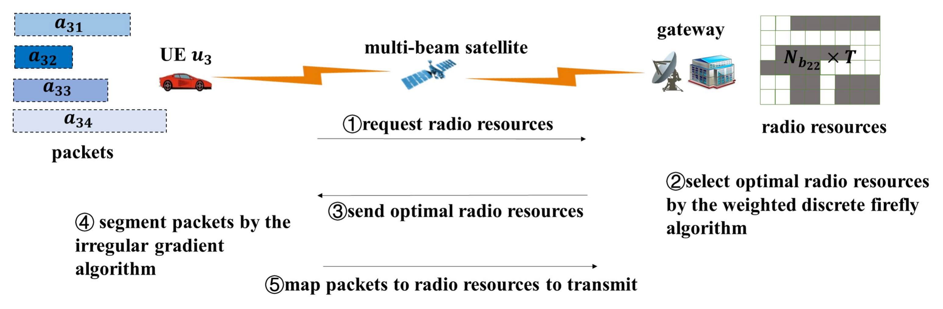
Figure 2 describes the transmission process of multi-beam satellite communication systems from resources requests to packet transmitting. At first, after the connection between satellites and users is established, resources requests are transmitted to the gateway. Then, the gateway optimizes the radio resources of the beam of the satellite according to the request. Next, the optimal resources are assigned to users’ packets. Then, the packets are segmented into smaller packets. In the end, the smaller packets are mapped to the optimal resources, and users can transmit the packets by the optimal resources.
3.2. User Connection Model
In the multi-beam satellite communication system, multiple beams can be used to serve one user’s packets. Therefore, the traditional two-dimensional resource grid cannot accurately describe the characteristics of multi-satellite and multi-beam connection with multiple connection modes, which leads to an increase in the complexity of resource allocation.
In the multi-satellite multi-beam cooperative communication system, there are mainly four connection models between satellites and users, as shown at the time
in
Figure 1. The first model is the single-satellite single-beam connection model, where the user
is only connected to a beam of the satellite
. The second model is that the user connects to multiple beams of one satellite. The user
connects to two beams of the satellite
. Another model is the multi-satellite single-beam connection model, where the user
connects to a beam of the satellite
and a beam of the satellite
. The last model is the connection between the user and multi-satellite multi-beam. The user
is connected to a beam of the satellite
and two beams of the satellite
at the same time. In this case, the users’ packets are transmitted simultaneously by a beam of the satellite
and two beams of the satellite
according to the result of resource allocation.
3.3. System Propagation Model
In this paper, we mainly consider the effects of large scale fading (including free space loss, scintillation effect, cloud and rain attenuation, and oxygen absorption), small scale fading, transmission delay, and doppler effect under different beams. The difference of channel fading under different beams is mainly reflected in the difference in elevation angle, distance, and carrier frequency. We will conduct a detailed analysis below:
3.3.1. Satellite Channel Model
In this paper, different packets are transmitted through different beams of one satellite or different beams of different satellites. Therefore, we mainly consider the influence of satellite channels on signal transmission in two different scenarios. One is the difference of channels in different beams of one satellite. The other is the difference of channels in different beams of multiple satellites.
In the LEO satellite communication system, as shown in
Figure 3, the signal of the packet
is mainly influenced by large scale fading (including free space loss, scintillation effect, cloud and rain attenuation, and oxygen absorption), small scale fading, transmission delay, and doppler effect. The channel impulse response of the beam
of the satellite
which is used to transmit the packet
can be expressed as:
where
is large scale fading parameter.
represents free space loss.
,
,
are scintillation effect, rain attenuation, and oxygen absorption, respectively, which we set to 1, 1.585, and 1.
is the transmission delay.
is the doppler effect.
is the value of doppler shift in the beam
of the satellite
.
is small scale fading defined as TDL channel in 3GPP.
As shown in
Figure 3b, at the current time, the satellite
can only provide user
with one beam, and other beams of satellite
cannot be used for transmission because the band of other beams is occupied or the channel fading is serious. However, the user
needs to transmit a large number of packets and has the highest priority, the adjacent satellite
will be scheduled to serve the user
. As shown in
Figure 4, the distance between the satellite
and user
is 1500 km and the distance between the satellite
and user
is 1700 km. When the distance between satellite and user is different, the free space fading, doppler shift, and transmission delay are different.
3.3.2. Free Space Loss Model of Satellite Channel
Figure 3a shows that packets are transmitted through different beams of one satellite. In different beams, the distance between the user and the satellite can be regarded as the same. Different beams use different carrier frequencies for transmission. According to
Figure 4a, we can see when the distance between the user and the satellite is 1500 km, the free space fading generated by beam 1 with 28.1 GHz and beam 2 with 28.2 GHz is 245.5 dB and 245.7 dB, respectively. In order to better show the influence of the distance on free space fading, doppler shift, and transmission delay, we have underlined the free space fading, doppler shift, and transmission delay values of satellites located at 1500 km and 1700 km in
Figure 4. The red line indicates the free space fading, doppler shift, and transmission delay of the satellite
with a height of 1500 km. The black line indicates the free space fading, doppler shift, and transmission delay of the satellite
with a height of 1700 km.
Figure 3b shows that packets are transmitted through different beams of multiple satellites. In different beams, the distance between the user and the satellite is quite different. At the same time, different beams use different carrier frequencies for transmission. It can be seen in
Figure 4a that when the distances between satellites and users are 1700 km and 1500 km, the free space fading of beams with the same carrier frequency of 28.1 GHz is 248 dB and 245.5 dB, respectively. The free space fading can be expressed as:
where
c is the velocity of light.
and
are gain of transmitter and receiver, respectively, which we set to 1.
L is system loss parameters.
is the distance between the satellite and the user, which can be get from Equation (
3).
is the carrier frequency. The carrier frequency of different beams is different. As the distance
between the satellite
and the user
and the carrier frequency
of the beam
increases, The free space fading
of the beam
of the satellite
transmitted the packet
increases.
where
.
is the angle between
and
r. The range of
is
.
and
are the longitude and latitude of the user
that generates the packet
, respectively.
is the longitude of the satellite
.
is the radius of the earth.
r is the orbit radius of the satellite.
3.3.3. Doppler Shift Model of Satellite Channel
In the satellite communication system, doppler shift is caused by relative movement between satellites and users. Doppler shift leads to carrier frequency offset, constellation rotation, and inter-carrier interference, resulting in serious signal distortion, high bit error rate, affecting system throughput. As shown in
Figure 4b, when the distance between user and satellite is 1500 km in scenario (a) in
Figure 3, the doppler shift of both beams is
. In scenario (b) in
Figure 3, when the distance between satellites and users is 1700 km and 1500 km, the doppler shift is
,
, respectively. Doppler shift in satellite channel can be expressed as:
where
. The value of
,
r, and
are as described above.
is maximum access angle which is
.
3.3.4. Transmission Delay Model of Satellite Channel
As shown in
Figure 4c, when the distance between user and satellite is 1500 km in scenario (a) in
Figure 3, the transmission delay at the same distance is 34ms. In scenario (b) in
Figure 3, when the distance between satellites and users is 1700 km and 1500 km, the transmission delay is 56.5 ms and 50 ms, respectively. The transmission delay can be simplified as:
where
is the distance between the satellite
and the user
which generate the packet
.
c is the velocity of light. The value of
is as described above. As the distance of the satellite increases, the transmission delay increases.
4. Multi-Beam Satellite Cooperative Transmission Scheme Based on Cross-Layer and Cross-Dimension Resources Optimization and Irregular Gradient Adaptive Packets Segmentation
In this section, at first, the multi-beam satellite cooperative transmission scheme based on cross-layer and cross-dimension resources optimization and irregular gradient adaptive packet segmentation is mathematically expressed. Then, the cross-layer and cross-dimension radio resources optimization model based on the weighted discrete firefly algorithm and the adaptive packet segmentation scheme based on the irregular gradient algorithm are introduced. Finally, we put forward the user satisfaction index and evaluate the proposed algorithm.
4.1. Problem Formulation
According to the analysis of the multi-beam satellite communication system, the availability of multi-dimensional radio resources changes dynamically. At the same time, the influence of CSI and QoS should be considered when optimal resources are selected. Since the optimal resources in the multi-beam satellite communication system are discontinuous, packets need to be effectively segmented to adapt to the optimal resources. Therefore, we propose a multi-beam satellite cooperative transmission scheme based on cross-layer and cross-dimension resources optimization and irregular gradient adaptive packets segmentation.
In this paper, in order to focus on the problem of resource allocation, we assume that satellites and beams have been connected to users. At the same time, considering the connection model between users and satellites mentioned above, the interference of the packet
can be expressed as:
where the first part of Equation (
6) is the interference to the packet
caused by other packets
of the user
which are transmitted by the same beam of the same satellite. The second part of Equation (
6) is the interference to the packet
caused by other packets
of other users
which are transmitted by the same beam of the same satellite.
is the transmitting power of the beam
of the satellite
. In this paper, the transmitting power of each beam is set to the same, 60 W.
is the channel gain of the beam
of the satellite
transmitted the packet
. According to the propagation model described above, different beams have different channel gains. The channel gain of each beam changes with changes in large scale fading, small scale fading, transmission delay, and doppler shift. The channel gains of different beams which are used to transmit packets are different. The packets are suffered from different interference. As the channel gain of the beams increases, the interference suffered by the packets increases.
Let the binary variable
represent the connection between beams and users. When
, it means that the user
connects to the beam
of the satellite
, otherwise,
. The bandwidth occupied by segmentation packets
is
where
B is the system bandwidth.
N is the number of subchannels of the satellite
and
is the number of subchannels occupied by the packet
in the frequency domain.
At the receiver, we separately calculate the SINR of the beams that transmit different parts of the packet. The SINR of the beam
of the satellite
that transmit the segmentation packet
is
where
is Gaussian white noise. According to the propagation model described above, different beams of different satellites have different channel gains. The channel gain changes with the randomness of the channel.
is the interference suffered by the packet
as mentioned by Equation (
6). When the beam
of the satellite
connect to the user
which generate the packet
, that is,
and
.
is the power to transmit the packet
.
Therefore, the system capacity is:
According to the above parameter description, the mathematical model of radio resource allocation problem with the optimization goal of maximizing the system capacity can be defined as:
Equation (
11) introduces that radio resources of the beam
of the satellite
occupied by different packets,
and
, cannot be overlapped at the same time. Equation (
12) indicates that different packets,
and
, can occupy the radio resources of the beam,
and
, at the same time, which belong to different satellites,
and
. Equation (
13) indicates that the gateway can allocate resources or not according to the judgment conditions in the process of resource allocation. Equation (
14) means that the user
can connect multiple beams of multiple satellites simultaneously. There will always be a beam of a satellite connected to the user. The transmitted power is limited by the total power given by Equation (
15).
4.2. A Cross-Layer and Cross-Dimension Radio Resources Optimization Model Based on the Weighted Discrete Firefly Algorithm
As shown in
Figure 5, a cross-layer and cross-dimension radio resources optimization model based on the weighted discrete firefly algorithm is recommended by considering the mapping model between cross-layer and cross-dimension resources and fireflies and the influence of CSI and QoS as the weight of fireflies’ attraction.
In this paper, the position of each firefly represents the radio resource
of the beam
of the satellite
and the CSI of radio resources and the QoS of packets are expressed as the weight of the brightness
of the firefly. The ratio of bandwidth and SINR
is the adaptive value. The matrix
is used to represent the result of each optimization, and the dimension of the matrix is
.
S is the total number of satellites in the system.
is the total number of beams in the system.
U is the total number of users in the system.
A is the total number of packets in the system.
N is the total number of sub-channels provided by each beam of each satellite.
T represents the exchange time of one request process, that is, the total time of one resources allocation process. The set of the optimal radio resources selected each time is represented as
y. The representation of the matrix
is as follows:
Among them . is the optimal satellite. is the optimal beam. is the served user. is the transmitted packet. is the frequency index of the optimal radio resources. is the time index of the optimal radio resources.
The firefly’s brightness
can be written in the following equation:
where
is the value of initial attraction, that is, the value of attraction when
.
is the given fixed light absorption coefficient.
r is the distance between two fireflies. CSI and QoS are the weight of
r. The distance between two fireflies can be expressed as:
where
represents the difference between two radio resources.
and
represent different radio resources.
k represents dimension, and
represents the position of the
i-th firefly in dimension
k.
The position of the
i-th firefly moved by the influence of
j-th firefly can be defined as:
where the second part in the above equation represents the influence of attraction. The third part represents the random parameter. The
represents the random value between [0, 1].
is a random parameter. Since the radio resource allocation in the multi-beam satellite communication system is a complex discretization problem, this paper adopts
to discretize the radio resources.
The ratio of the bandwidth to SINR of the user’s packet
is determined as fitness function
to find the optimal resources index. The bandwidth occupied by the packets
of user
within time
T is
The total bandwidth of the beam of the satellite is B, which is divided into N subchannels. The bandwidth occupied by each subchannel is in a symbol. is the number of subchannels of the beam occupied by the packet in the frequency domain, which is different in different beams of different satellite occupied by the packet . The bandwidth occupied by the packet of the beam of the satellite is in a symbol. is the number of symbols of the beam occupied by the packet in the time domain, which is different in different beams of different satellite occupied by the packet . The bandwidth occupied by the packet of the beam of the satellite is . In summary, The bandwidth of all beams of all satellites occupied by the packet is in T, that is, in a TTI. In the case of channels with different SINR, the index of the optimal radio resources, and , are different. The bandwidth occupied by the packet is also different.
The formula defined as the fitness function is as follows:
where
is the bandwidth occupied by the packets
of user
within time
T.
is the SINR of the packets
.
The detailed flow chart of the weighted discrete firefly algorithm using
as the fitness function is given in Algorithm 1.
| Algorithm 1 Improved discrete firefly algorithm |
| Input: source-index, num-source, SINR, QoS, = 1, = 0.5, = 0.5, = 0.9, maximum iteraton t-max. |
| Output: best-source-index. |
| while
do |
| for do |
| for do |
| if then |
| Move firefly i towards firefly j by considering the |
| distance between i and j using; |
| Update source-index; |
| Update light intensity. |
| else |
| Update parameter; |
| . |
| end if |
| end for |
| end for |
| end while |
4.3. An Adaptive Packets Segmentation Scheme Based on the Irregular Gradient Algorithm
In the multi-beam satellite communication system, optimal resources are taken as the weight of gradient segmentation. The packets are segmented in an irregular way to adapt to the discontinuous optimal resources, which are transmitted cooperatively by multi-satellite to improve the spectrum efficiency and maximize the utilization of resources.
According to 3GPP, radio resources are divided into time domain resources and frequency domain resources. In the time domain, they are sequentially divided into frames, subframes, slots, and symbols. In the frequency domain, they are divided into resource blocks (RB) and resource elements (RE). Unlike LTE, in order to adapt to the multiple scenarios of 5G, the transmission time interval (TTI) of 5G is defined as a slot. Moreover, in the frequency domain, subcarrier spacing can be set as 15 kHz, 30 kHz, 60 kHz, 120 kHz, and 240 kHz according to different scenarios. The uplink and downlink channels are no longer fixed slots, and the slots can be flexibly allocated according to the demand for packets.
Similar to the 3GPP 5G Non-Terrestrial Network (NTN), the radio resources of the NTN in 3GPP are also divided into time domain resources and frequency domain resources. The difference from the ground is that a higher frequency band is used in NTN for transmission.
As shown in
Figure 6, we use the same resource division method as 3GPP. In the time domain, the slot is the smallest unit of TTI, which contains 14 OFDM symbols. In the frequency domain, the system bandwidth is divided into multiple RBs and each RB contains 12 consecutive subcarriers. Each RB occupies 12 consecutive subcarriers and a symbol. In each TTI, we allocate RBs according to user demands. The maximum allocatable slot resources are 14 OFDM symbols in a TTI, and the maximum frequency domain resources that can be allocated are related to the allocatable bandwidth and subcarrier spacing. Different from 3GPP, the relative movement between satellites and users and long distances cause large delays, so we mainly use 120 kHz subcarrier spacing to reduce the interference of carriers and frequency offset in our system.
Figure 6 shows a detailed explanation of the adaptive packet segmentation scheme based on the irregular gradient algorithm. In this paper, the user generates packets with different delays, different QoS requirements, and different sizes at the application layer. After processing by high layers, the packets are multiplexed at MAC. It is different from the rule in which packets are multiplexed into fixed-size transmission blocks in the 5G MAC. In this paper, the packets are segmented according to optimal resources. The segmented packets are padding zeros according to the size of the transmission block to ensure that packets can be sent when resources are insufficient. In the PHY, the packets are coded and modulated, and mapped to the corresponding RB.
In this paper, while ensuring transmission quality, the scattered radio resources are integrated to transmit packets to improve spectrum efficiency. As mentioned above, the optimal resources RB are found according to the cross-layer and cross-dimension radio resources optimization model based on the weighted discrete firefly algorithm. When the size of the optimal continuous RB is smaller than the size of the packet that needs to be transmitted, the packet is divided into smaller packets at the MAC according to the size of the optimal continuous RB. Then, zero padding is performed according to the fixed size of the transmission block. The above steps are cyclically executed until the RB in this TTI is used up or all packets are successfully transmitted.
At the receiver, the user completes frame synchronization and slot synchronization in the PHY according to Primary Synchronization Signal (PSS) and Secondary Synchronization Signal (SSS) to receive the physical signal in each beam. After multiple TTIs, the segmented packets transmitted by different satellites and beams are cached to the receiver. When all the segmented packets of one packet are transmitted to the receiver, the segmented packets are sorted at the MAC layer according to their sequence numbers and reassembled. The reassembled packets are transmitted to the upper layer.
4.4. User Satisfaction Index
In this paper, the user satisfaction index is expressed as
and defined as the ratio of the bandwidth actually allocated to packets to the bandwidth required by users. If the ratio is equal to 1, it means that the radio resources allocated to users can fully meet the demands of users. Otherwise, the smaller the value is, the fewer radio resources are allocated to packets, and the demands of users cannot be met.
where
is the bandwidth actually allocated to all packets which are generated by the user
.
is the bandwidth required by the all packets which are generated by the user
in all beams of all satellites.
The user satisfaction index of the adaptive packet segmentation scheme based on the irregular gradient algorithm is 18% higher than that without the irregular gradient algorithm.
5. Simulation Results and Performance Analysis
In this paper, the proposed multi-beam satellite cooperative transmission scheme based on cross-layer and cross-dimension resources optimization and irregular gradient adaptive packet segmentation is evaluated by simulation based on MATLAB R2019a. In order to verify the proposed algorithm in this paper, the multi-beam satellite communication system is built, where the satellite constellation mainly adopts the features of OneWeb, whose parameters are shown in
Table 1.
As shown in
Figure 7, the user generates multiple packets. Firstly, each packet is mapped to the radio bearer according to QoS. Secondly, the packets are segmented according to allocated radio resources, and each segmented packet
is tagged with
c. Thirdly, each segmented packet is mapped to the different beams for transmission and processed in satellite. The receiver receives the packets of each beam separately. The PSS and SSS received are autocorrelated with the local SSS and PSS in order to complete the frame and time slot synchronization within each beam. Then the receiver caches the received packets. After multiple TTIs, when all segmented packets of one packet had been received, the segmented packets are sorted and reassembled according to their own label
c.
Under multi-beam satellites coverage, we mainly consider the normalized system throughput and user satisfaction index with four communication scenarios as shown in
Figure 8, that is, single-satellite single-beam multi-user, single-satellite multi-beam multi-user, multi-satellite single-beam multi-user, and multi-satellite multi-beam multi-user. In the simulation, the parameters of the firefly algorithm are shown in
Figure 8. Comparing scenario (a) with (b), it can be clearly seen that the normalized system throughput is significantly improved due to the increase of beam. Comparing scenario (b) with (c), there is interference between users when the beams of different satellites share bandwidth. The SINR is reduced. The normalized system throughput is reduced. Comparing scenario (b) with (d), when multiple satellites serve multiple users, while the quality of resources that users can allocate become worse, the normalized system throughput is even much higher than that of other scenarios because of the large bandwidth, coordination transmission between multi-beam and flexible allocation according to user demands.
As shown in
Figure 9,
Figure 9a abstractly represents the part of radio resources of multi-beam satellites, where the yellow parts are available resources that can be allocated to users.
Figure 9b abstractly shows the part of radio resources that are allocated to different packets in scenario (d). Different colors indicate radio resources that are allocated to different packets.
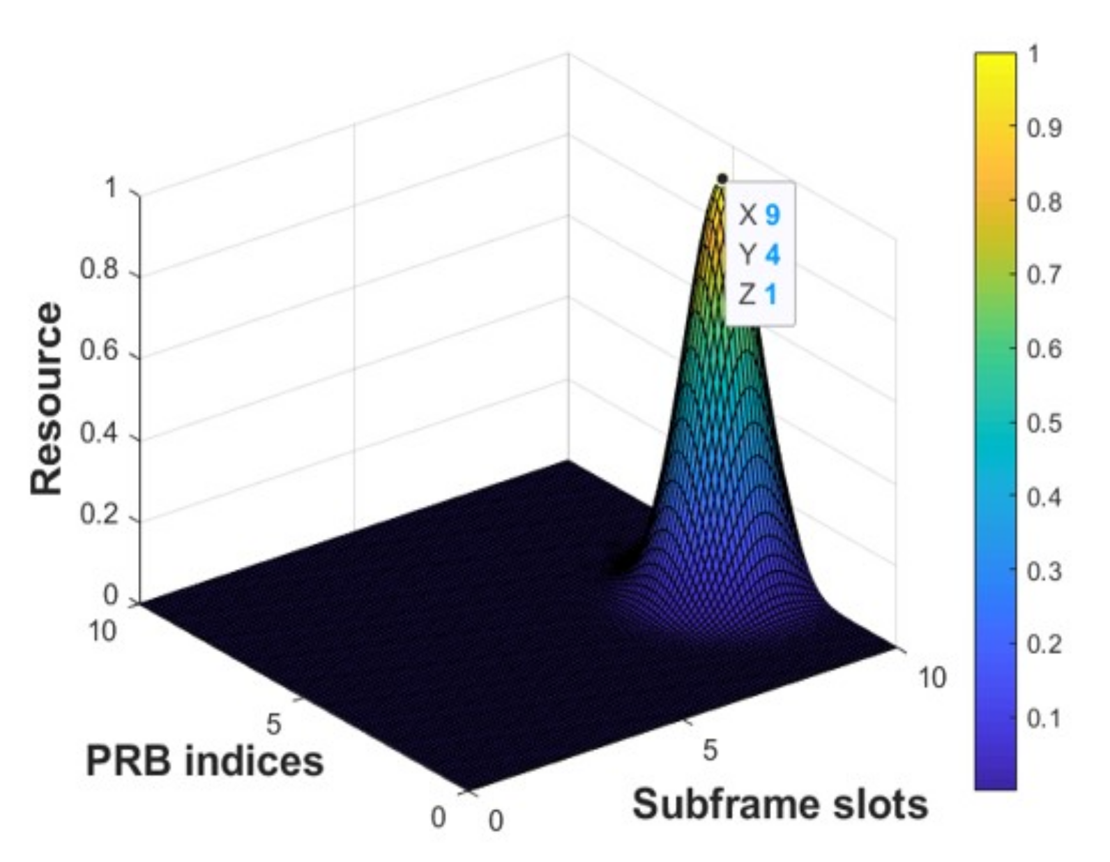
Figure 10 shows the index of the optimal resources that are selected in an iteration by using the cross-layer and cross-dimension radio resources optimization model based on the weighted discrete firefly algorithm.
In this paper, as shown in
Figure 11a, there is data diversity in the multi-beam satellite communication system which means that the data of one user is transmitted through different physical channels (such as different beams of one satellite or different beams of multiple satellites) after segmentation. The SINR of each beam is not superimposed, and the packet is not repeatedly superimposed and sent. In order to better show that the difference of the SINR of each beam, we have underlined the relationship between SINR and BER of different beams in
Figure 11 respectively. When the SINR of the beam
is 1.5, the BER of the beam
is 0.12. When the SINR of the beam
is 2.1, the BER of the beam
is 0.13. When the SINR of the beam
is 2.5, the BER of the beam
is 0.15. In this paper, unlike traditional MIMO systems, we use beams with similar SINRs to transmit different packets to achieve data diversity. After segmenting packets at the transmitter, the received segmented packets are buffered at the receiver. After multiple TTIs, the packets will be reorganized and combined into a packet. Finally, the data packet would be processed.
According to the above analysis, the multi-beam satellite cooperative transmission scheme based on cross-layer and cross-dimension resources optimization and irregular gradient adaptive packet segmentation can significantly improve the normalized system throughput. However, the normalized system throughput is different under the proposed algorithm with different iterations.
Figure 11b shows that as the number of iterations increases, the normalized system throughput increases and then remains at a stable amount. When the normalized system throughput reaches stabilization, the increase of the number of iterations does not significantly improve the normalized system throughput, but the time required still increases. Therefore, in this paper, the number of iterations is set to 3.
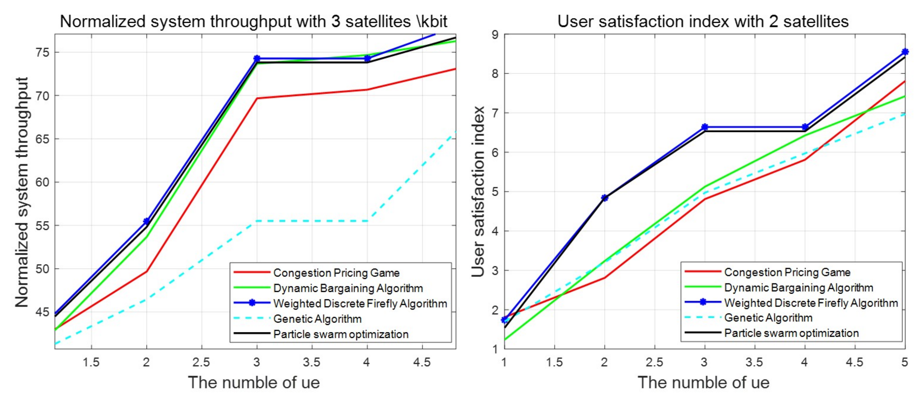
As shown in
Figure 12, in the multi-beam satellite communication system, we adopt other resource allocation algorithm to compare with the proposed algorithm in this paper, which are congestion pricing game algorithm, dynamic bargaining algorithm, particle swarm optimization algorithm, and genetic algorithm. According to the research results in references [
47,
48], we found that, at the same time, there are 3 multi-beam satellites covering users at
,
,
or 2 multi-beam satellites covering users at
,
. We analyze the influence of different numbers of satellites on the normalized system throughput. It can be clearly seen from
Figure 12 that with the increase of the number of satellites, the normalized system throughput is also increasing. Among them, the worst performance is the genetic algorithm. The best one is the proposed algorithm in this paper. In other words, with the same number of satellites under optimal parameters, the proposed algorithm in this paper can better improve the normalized system throughput. After selecting the optimal resources, packets are segmented to be adapted to the optimal resources, which can make full use of resources, increase the transmission rate, and increase the system throughput at the same time.
We evaluate the performance of different algorithms according to the user satisfaction index proposed above. As shown in
Figure 13, the user satisfaction index using the proposed algorithm in this paper is higher. The proposed algorithm carries out cross-layer and cross-dimension optimization. Firstly, the optimization selection is carried out among different satellites. Then the optimization selection is carried out among beams of the optimal satellite. Finally, the optimal resources are carried out among radio resources. It can be seen from
Figure 12 and
Figure 13 the proposed algorithm in this paper can effectively improve normalized system throughput and user satisfaction index.


 ,
, 


