Article

Multi-Objective Grasshopper Optimization Based MPPT and VSC Control of Grid-Tied PV-Battery System

1
Department of Electrical Engineering, NIT Srinagar, Srinagar 190006, India
2
Department of Electrical Engineering, University of Kashmir, Srinagar 190006, India
3
BEARS, NUS Campus, University Town, Singapore 138602, Singapore
4
Ingenium Research Group, Universidad Castilla-La Mancha, 13071 Ciudad Real, Spain
*
Author to whom correspondence should be addressed.
Electronics 2021, 10(22), 2770; https://doi.org/10.3390/electronics10222770
Submission received: 18 September 2021 / Revised: 1 November 2021 / Accepted: 9 November 2021 / Published: 12 November 2021

Abstract

:
This article presents the control of a three-phase three-wire (3P-3W) dual-stage grid-tied PV-battery storage system using a multi-objective grass-hopper optimization (MOGHO) algorithm. The voltage source converter (VSC) control of the presented system is implemented with adaptive kernel width sixth-order maximum correntropy criteria (AKWSOMCC) and maximum power point tracking (MPPT) control is accomplished using the variable step-size incremental conductance (VSS-InC) technique. The proposed VSC control offers lower mean square error and better accuracy, convergence rate and speed as compared to peer adaptive algorithms, i.e., least mean square (LMS), least mean fourth (LMF), maximum correntropy criteria (MCC), etc. The adaptive Gaussian kernel width is a function of the error signal, which changes to accommodate and filter Gaussian and non-Gaussian noise signals in each iteration. The VSS-InC based MPPT is provided with a MOGHO based modulation factor for better and faster tracking of the maximum power point during changing solar irradiation. Similarly, an optimized gain conventional PI controller regulates the DC bus to improve the power quality, and DC link stability during dynamic conditions. The optimized DC-link generates an accurate loss component of current, which further improves the VSC capability of fundamental load current component extraction. The VSC is designed to perform multi-functional operations, i.e., harmonics elimination, reactive power compensation, load balancing and power balancing at point of common coupling during diverse dynamic conditions. The MOSHO based VSS-InC, and DC bus performance is compared to particle swarm optimization (PSO) and genetic algorithm (GA). The proposed system operates satisfactorily as per IEEE519 standards in the MATLAB simulation environment.

1. Introduction

The grid-tied Photovoltaic (PV) system has become a natural choice for green energy, considering PV power’s sharp cost curtailment [1]. The grid-tied PV systems have shown considerable commitment as a stable and reliable participant in the modern power grid [2,3].
Maximum power point tracking (MPPT) is crucial for achieving the desired efficiency and payback time of PV systems [4]. In [5,6], a detailed review of widely used traditional, intelligent and optimization based MPPT methods have been provided. In [7], an exhaustive review of artificial neural network (ANN) based MPPT has been provided along with ANN-based variable step-size MPPT is also proposed. The perturb and observe (P&O) and incremental conductance (InC) based MPPTs are among the widely implemented techniques due to their ease of implementation, reduced computational burden and adequate efficiency. In conventional InC and P&O techniques, the step size or duty cycle perturbation ( Δ D ) remains fixed, where the trade-off has to be made between faster response and oscillations across the maximum power point (MPP). During steady-state smaller Δ D is desirable, which reduces the operating point oscillations across MPP and eventually PV power ( P PV ) oscillations. Whereas, during a dynamic state larger Δ D contributes to the faster dynamics and helps in the quick attainment of the MPP [8].
The variable step-size P&O/InC MPPT offers the extra advantage of easy implementation and lower computational burden, can be implemented by various methods, where most of the algorithms are very similar, i.e., Δ D changed according to the multiplication of modulation or scaling factor ( δ ) and derivative of power to current ( δ Δ P / Δ I ) [9], or to voltage ( δ Δ P / Δ V ) [10] or to step-change in duty cycle ( δ Δ P / Δ D ) [11]. In [9] variable step-size InC (VSS-InC) MPPT is implemented for the boost control, which shows good dynamic response but suffers from high overshoot due to fixed δ . In [10] according to the experimental observation, VSS-InC/P&O MPPT controls the boost converter, where δ is kept between 1 to 2.5% of the inverse of PV current ( I PV 1 ) . In [11] δ is autotuned for the robust performance of buck converter control by VSS-P&O MPPT at the cost of the computational burden. In [12], load current based adaptive step size MPPT is suggested, D is made a function of derivative of current to change in duty cycle ( Δ I / Δ D ) where δ is kept constant. In [13], for the VSS-InC method, δ = 0.001 is chosen at the design stage and Δ D is made a function of the power derivative on the difference of voltage and current derivatives ( δ Δ P / ( Δ V Δ I ) ) . The selection of δ is crucial for the MPPT performance and bad selection may introduce steady-state oscillations and slow down the tracking speed. In [14] the δ < Δ D max / | dP / dV | is suggested to improve the performance of VSS-InC MPPT. In [15], a modified P&O method utilizes a direct duty ratio control for achieving drift-free MPPT operation at the first step-change in duty cycle during rapidly changing irradiation levels. The InC—with self-adaptive and immanent decision-making capability—is presented in [16], where three consecutive points on the power-voltage curve accurately detect the steady and dynamic conditions. In the presented work, the δ has been optimized for the VSS-InC MPPT as the first objective of the implemented multi-objective grasshopper optimization (MOGHO) algorithm [17]. The designing of δ is performed on an offline basis, it does not affect the computational complexity of the VSS-InC, improves the MPP tracking speed and accuracy.
The DC bus is of utmost importance for the stability of the system. The DC link voltage ( V dc ) is regulated by the conventional PI controller. Meta-heuristic optimization techniques (MOT) have been frequently used for PI controller gain optimization, which reduces the V dc transients during a steady and dynamic state and increase the DC link stability [18]. In [19] the Jaya algorithm is employed to increase the power quality by optimizing the PI controller gains and filter parameters. The Jaya algorithm is a specific parameter less technique that is robust but less efficient. In [20,21], the DC link optimization with the salp swarm optimization (SSO) technique and generalized normal distributed algorithm (GNDO) are presented. The SSO technique delivers a poor convergence rate on higher-dimensional problems and GNDO is inspired by the Gaussian distribution and require no special controlling parameters. In [22], the comparative analysis of regulated V dc with whale optimization algorithm (WOA) and particle swarm optimization (PSO) is performed. Both WOA and PSO suffers from slow convergence, low accuracy, and local minima stagnation. Many potent deep reinforcement learning (DRL) based optimization techniques, i.e., soft actor-critic (SAC) [23], deep deterministic policy gradient (DDPG) [24], expert assistant DDPG (EADDPG) techniques [25], etc. can further be utilized for the performance enhancement of grid-tied PV systems. In the presented work, MOGHO is utilized for the V dc regulation by PI controller gains optimization as the second objective of multi-objective optimization techniques. The MOGHO offers a better convergence rate and balance between the exploration and exploitation phase which ensures to reduce the chances of local minima stagnation [17].
Numerous VSC control algorithms of various domains such as time domain, frequency domain, adaptive controls etc. for the grid-tied PV system have been investigated and implemented by the researchers. The synchronous reference frame (SRF), power balance theory (PBT), and many more [26] are among the widely used time-domain techniques, which are easy to implement and have less computational burden but produce more steady-state error. In [27], active reactive power control of instantaneous and average nature (IARC and AARC), balanced positive sequence compensation (BPSC), positive-negative sequence compensation (PNSC), etc. based on VSC controls have been proposed. The frequency-domain controls, i.e., Kalman filter-based controls (KFC) [28], Stockwell transformation (ST), etc. [29] have higher computational complexity and slow convergence speed. On the other hand, adaptive controls have a moderate computational burden and deliver reduced steady-state error with a faster convergence speed. Adaptive algorithms such as least mean square (LMS) [30], least mean fourth (LMF) [31], maximum correntropy criteria (MCC) [32] deliver faster convergence and robustness. The LMS control due to the fixed step size, produce a relatively higher steady-state error as compared to the LMF, which acts as a higher-order filter for the error signal. The MCC utilizes the Gaussian kernel which is effective against both Gaussian and non-Gaussian noise signals. Many advanced versions of LMS, LMF and MCC, i.e., hyperbolic cosine LMS (HCLMS) [33], hyperbolic tangent function (HTF) [34], LMS-LMF [35], adaptive neuro-fuzzy LMS (ANF-LMS) [36], zero attracting normalized LMF (ZAN-LMF) [37], normalized MCC (NMCC) [38], fixed forward prediction (FFP) [39], adaptive kernel width sixth-order MCC (AKWSOMCC) [40], etc. The HC-LMS offers minimal dynamic oscillations, HTF acts as a higher-order filter, which offers reduced mean square error (MSE), combined LMS-LMF reduces the shortcomings of LMS control by switching between second and fourth-order filter, but the performance of both controls reduces during heavily tailed Gaussian noises due to fixed step-size. The ANF-LMS delivers neuro-fuzzy tuned step-size for enhanced performance but increases the computational complexity. The ZAN-LMF, NMCC and FPP vouch for faster convergence rate and speed but have a high steady-state error due to fixed step size. The AKWSOMCC can handle Gaussian and non-Gaussian noises efficiently, while acting as a higher-order filter and delivering a better fundamental load current component. The function approximation and noise cancellation offered by AKWSOMCC are better than its peer adaptive controls due to adaptive kernel width, which also improves the convergence speed despite computational complexity. The proposed AKWSOMCC algorithms parameters are carefully tuned depending on their application ensuring the desired performance during the diverse dynamic condition. The optimized MPPT and DC bus further enhance the capability of the proposed control.
In the presented work, the MOGHO algorithm fulfils two objectives by providing the optimum δ for VSS-InC MPPT and PI controller gains ( k p ,   k i ) for the V dc control, in a three-phase three-wire (3P-3W) grid-tied dual-stage PV-battery storage system. The VSC is controlled by the AKWSOMCC algorithm. During steady-state and dynamic states, the VSC control performs harmonics suppression, reactive power compensation, load balancing and active power balancing at the point of common coupling (PCC). The battery storage system maintains the power balance during dynamic conditions. The optimized DC bus generates an accurate loss current component, which further enhances the system’s performance. The main attributes of the proposed work are as follows:
  • MOGHO based scaling factor ( δ ) optimization for VSS-InC MPPT to achieve faster tracking and reduced power oscillations at MPP.
  • MOGHO based PI controller gains ( k p ,   k i ) optimization for the V dc control and generation of an accurate loss current component ( i L o s s ).
  • AKWSOMCC based VSC control for fundamental load current component extraction.

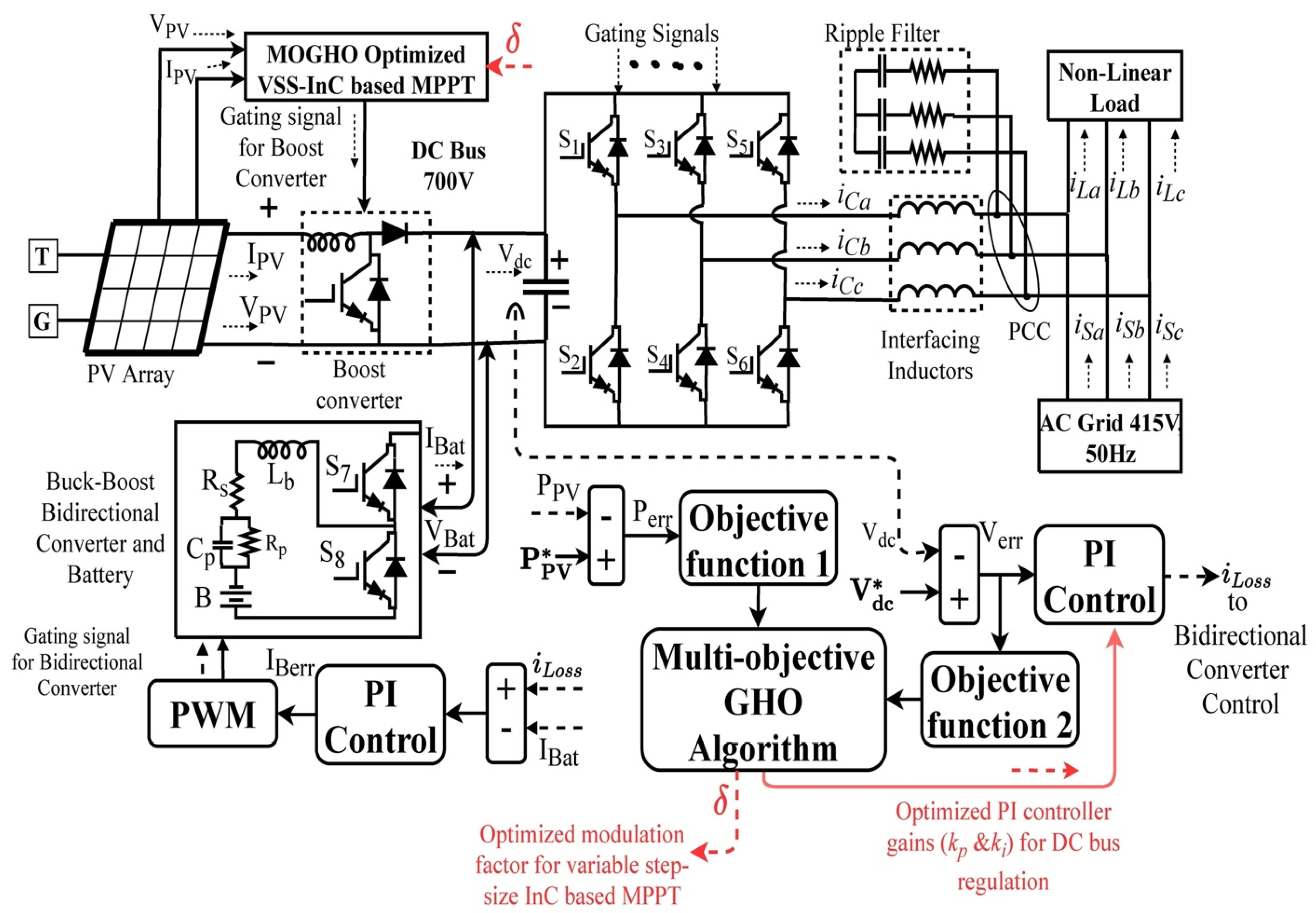
2. System Description

The proposed topology is presented in Figure 1. A dual-stage PV system of 33 kW along with battery storage is integrated with the 3P-3W grid. The PV array and battery design parameters are provided in Appendix A. The MOGHO algorithm optimizes the δ of VSS-InC based MPPT and PI controller gains ( k p & k i ) for V dc regulation. The boost converter is controlled by the gating signal delivered by the MPPT to stabilize the V PV . The battery current control during the charging and discharging phase is aided by the bi-directional buck-boost converter. The coupling capacitor at the DC link connects the DC and AC systems. The 3P-3W converter is attached to the PCC through interfacing inductors and ripple filters. The non-linear load of 16.5 kW and distribution grid of 415 V at 50 Hz are also attached to PCC.

3. Implemented Research Methodology

The implemented research methodology is depicted in Figure 2. The V PV ,   I PV , V dc , grid voltage magnitude ( V t ) , source voltage ( v S a b c ) and current ( i S a b c ) are sensed from the simulated system. The derivative of PV power ( P PV ) from the reference value ( P PV * ) is utilized for the generation of first integral square error (ISE-1) as the first objective function (Obj-1) to be minimized by the MOGHO algorithm as per (1). The optimized VSS-InC MPPT regulates the boost converter. At the DC bus, the comparison of V dc and ( V dc * ) is formed into second integral square error (ISE-2) as the second objective function (Obj-2) for MOGHO algorithm as per (2). The ISE as error indices is chosen, considering the decaying error with time. The MOGHO algorithm delivers the optimized δ and k p &   k i for the DC bus control. The accurate i L o s s current and feed-forward term ( W PV ) are provided to the AKWSOMCC for generating the switching signals of VSC control.
Obj 1 = 0 t ( P PV * P PV ) = 0 t P err 2
Obj 2 = 0 t ( V dc * V dc ) = 0 t V err 2

4. Multi-Objective Grass-Hopper Optimization Algorithm and Implementation

The MOGHO is a nature-inspired swarm intelligence (SI) technique that is based on the natural foraging and swarming behaviour of the grasshoppers. The grasshopper life cycle in two phases, i.e., nymph and adult are considered, where nymph does not have wings and move in the wind direction, whereas adults have wings and can travel a larger distance. The flow chart of the MOGHO is shown in Figure 3.
The grasshopper swarm is mathematically represented as (3), where P i is the fitness function, S i is the social interaction term, G i is the gravity term, A i is the wind advection term. The r 1 ,   r 2 , and r 3 are the random numbers within [0, 1], which introduces randomness.
P i = r 1 S i + r 2 G i + r 3 A i
The complete equation of the MOGHO is presented as per (4).
P i = r 1 [ j = 1 j i N S ( r ) ( d i j ) d i j ^ ] S i + r 2 ( g e g ^ ) G i + r 3 ( u e w ^ ) A i
The social interaction of grasshoppers is highly dependent on their social force and the distance between them. The social force ( S ( r ) ) is calculated as per (5), where f is the attraction intensity and l is the attractive length scale. The S ( r ) governs the social attraction and repulsion (or exploitation and exploration) of the grasshoppers. If f and l vary in the interval [0, 2.079] repulsion will occur and if f and l vary in the interval [2.079, 4] attraction will happen in grasshoppers. The grasshopper will be in its comfort zone when f and l remain exactly at 2.079. The d i j is the distance between i t h and j t h grasshopper and d i j ^ is a unit vector showing the direction of the grasshopper movement.
S ( r ) = f e x p ( r l ) e x p ( r )
d i j = | P j P i | ;   d i j ^ = P j P i d i j
The G i depending on gravitational constant ( g ) and unit vector e g ^ towards the centre of the earth. The A i term is a function of a constant u and unit vector e w ^ in wind direction. The grasshopper swarm behaviour of reaching and staying in the comfort zone can lead the iterative process towards local minima stagnation. For better chances of convergence, the modified equation of MOGHO is utilized as per (7).
P i = r 1 c 1 ( j = 1 j i N c 2 ( u b l b 2 ) S ( r ) ( d i j ) d i j ^ ) + T d ^
c = c 1 = c 2 = c m a x t ( c m a x c m i n t m a x )
The comfort zone coefficient ( c = c 1 = c 2 ) calculated as per (8) will have the same value but a different impact on the fitness function calculation as per (7). The c 1 is similar to the inertial weight in PSO, which reduces the search area as the iterations increases to balance the exploration and exploitation phase. The c 2 term reduces the repulsion, comfort, and repulsion zone (or the search area around global optima) between grasshoppers linearly to increase the chances of convergence and reduce the local minima stagnation. c m a x   and c m i n   are chosen as 1 and 0.000001 for the current problem. At the end of the iterative process, the MOGHO delivers the optimized δ and k p , k i gains. The presented system is aided with the four dedicated controls, i.e., optimized VSS-InC based MPPT control, bi-directional converter control, optimized V dc control and AKWSOMCC based VSC control.

4.1. MOGHO Based VSS–InC MPPT Control

The flow chart for the MOGHO based VSS-InC MPPT is shown in Figure 4. The VSS-InC varies the D with Δ D as perturbation step instead of fixed perturbation in conventional InC algorithm. The MPP is achieved when the variance of output conductance equals the negative of output conductance or the slope of the power–voltage (P–V) curve reaches zero as in the conventional InC algorithm as per (10).
Δ D = D ( n ) D ( n 1 ) = D m i n + δ ( P ( n ) P ( n 1 ) V ( n ) V ( n 1 ) )
Δ I P V Δ V P V = I P V V P V   At   MPP
The upper and lower bounds for δ optimization are selected based on experimental data presented in [7], which is 1–2.5% of I PV 1 and likewise the D min is also selected. The δ optimization is performed offline to reduce the computational burden of MPPT and optimized VSS-InC MPPT offers better efficiency, faster MPP tracking and reduced steady-state oscillations as compared to conventional InC MPPT algorithm. The variable and fixed step size MPPT operation are described in Figure 5. With a larger fixed step size, the MPP tracking will be very fast but chances of oscillations across MPP will be very high during steady-state, which gets reflected in higher P PV oscillations. The smaller fixed step size increases the efficiency and reduces the steady-state oscillations, but the tracking speed reduces. The variable step size uses a larger step size during irradiation change to reach quickly near the MPP and gradually reduces the step size near MPP to avoid the oscillations.

4.2. MOGHO Based Vdc Control

The battery current control and V dc control is shown in Figure 6. The DC bus is regulated by a conventional PI controller, which is tuned with the MOGHO algorithm. The MOGHO algorithm minimizes the Obj-2 and delivers the optimized gains for better stabilization of the V dc and generation of an accurate i L o s s current during dynamic conditions [13].
The comparison of i L o s s and battery current ( I Bat ) is fed to another PI controller, by which pulse width modulator (PWM) with logic gate, generates the adequate switching sequence. For the battery overcurrent protection, the I Bat is limited during charging and discharging up to I Bat max = 30 A. The I Bat control during the charging and discharging stage is performed by S7 and S8 switches of the bi-directional buck-boost converter.

5. AKWSOMCC Based VSC Control

The AKWSOMCC based compensator control is implemented by varying the kernel width as a function of the error signal as shown in Figure 7. The proper selection of the kernel width results in the smoothness of function approximation, better convergence rate and accuracy. The larger the kernel width, function smoothness will be more, but reduces sensitivity and may only behave as LMS. With a smaller kernel width, the locality of the training data is preserved, but the convergence rate will slow down. The proposed control with adaptive width brings the Gaussian and non-Gaussian noises of the error signal in the “observation window”. The adaptive Gaussian kernel width is a function of error signals, try to cover all Gaussian and non-Gaussian noises under the Gaussian bell curve for filtration. With adaptive kernel width, the whole network matrix or observation window need not be analysed, hence convergence speed increases. The sixth-order MCC acts as a higher-order adaptive filter with sixth-order power optimization. The MSE reduction with higher-order filters produces better steady-state behaviour. The adaptive kernel width ( σ n ) is a function of the error signal and fixed kernel width ( σ 0 ) as per (11). The pre-decided kernel width ( σ 0 = 10 ) will remain fixed during operation [27]. The error signal ( e n x ) is generated as per (12).
σ n 2 = e n x 2 + σ 0 2 ; where   x = ( a , b , c )
e n x = i L a µ p a W s p ; where   x = ( a , b , c )
The weight signals of each phase W pa ( n + 1 ) , W pb ( n + 1 ) and W pc ( n + 1 ) are generated as per (13).
W p x ( n + 1 ) = W p x ( n ) + e n x 5 μ μ p x σ n 2 e x p ( e n x 2 2 ( σ n 2 ) )   where   x = ( a , b , c )
The μ is the step size, μ p a , μ p b , μ p c are the unit templates or the in-phase components of source voltage generated as μ p a = v S x / V t (where x = a,b,c), where V t is the voltage magnitude and v S x will be the phase to ground source voltage. The W avg is the average weight signal calculated as per (14). The feed-forward term ( W PV ) is introduced in the VSC control for the power balancing is calculated as per (15), where V PV and I PV are the PV voltage and current signal.
W avg = 1 3 ( W p a + W p b + W p c )
W PV = 2 3 ( V PV I PV V t ) ;   where   V t = 2 3 ( v S a 2 + v S b 2 + v S c 2 )
The W sp will be the overall weight generated as per (16), which is further utilized for the current reference generation ( i s x * ; where x = a,b,c) as per (17). During specified power mode, the W sp f i x will replace the W sp as per (18) and generate the reference currents ( i s x f i x * ) as per (19).
W sp = W avg W pv
i s x = W s p μ p x ; where   x = ( a , b , c )
W s p f i x = 2 3 ( P f i x V t )
i s x f i x = W s p f i x μ p x ;   where   x = ( a , b , c )

6. Results and Discussion

The system is scrutinized under steady-state, irradiation variation mode, specified power mode, unbalanced grid voltage, abnormal grid voltage, unbalanced load, islanding, and re-synchronization mode, with optimized Duty cycle and V dc .

6.1. MOGHO Based VSS–InC MPPT Analysis

The V PV performance with MOGHO, PSO, and GA optimized δ for VSS-InC MPPT is compared to the non-optimized or initially selected fixed δ VSS-InC MPPT presented in Figure 8a. The non-optimized fixed δ is selected as 0.0001. During the steady-state at irradiation level of 1000 W/m2 the V PV variations are minimum with MOGHO tuned MPPT, whereas with fixed δ VSS-InC variations are significant and continuous. The PSO and GA optimized MPPT also reduce the V PV steady-state variations and performed comparatively better than non-optimized MPPT. During irradiation change from 1000 W/m2 to 600 W/m2 and vice versa, the MOGHO tuned MPPT manages to track MPP more quickly and accurately to settle down to the reference V PV .
The I PV comparison with MOGHO, PSO, GA optimized VSS-InC MPPT is compared with non-optimized VSS-InC MPPT in Figure 8b. During steady-state, MOGHO tuned MPPT maintains the I PV close to its reference value, while performing better than PSO and GA tuned MPPT. Even during irradiation variations, the I PV variations with MOGHO tuned MPPT remain minimum, which dies out more quickly due to faster and accurate tracking of MPP.
The P PV also performs better with MOGHO tuned VSS-InC MPPT in comparison with PSO and GA techniques as shown in Figure 8c. The P PV with adequate step size closely tracks P PV and deliver more average power, hence improving the MPPT efficiency. During irradiation variations, P PV variations are significantly reduced due to the accurate MPP tracking with MOGHO tuned VSS-InC MPPT.
The duty cycle (D) generated by the MOGHO tuned VSS-InC MPPT kept around the desired value, i.e., D = 0.137 as shown in Figure 8d. The D with MOGHO algorithm accurately tracks the MPP and takes very small steps to avoid the chances of oscillations around MPP. During dynamic state, the steps size increases to operate on a new load line and quickly track the shifted MPP for maximum power extraction. The D generated by MOGHO tuned MPPT during changing irradiations reduces the power oscillations to a greater extent and enhances the boost converter efficiency. Table 1 shows the comparative analysis of V PV , I PV settling time and boost converter efficiency with MOGHO, GA, PSO tuned MPPT and non-optimized VSS-InC MPPT with fixed δ . The VSC efficiency with MOGHO, GA, PSO tuned DC bus and non-optimized DC bus along with total dual-stage PV losses are also presented in Table 1.

6.2. MOGHO Algorithm Based DC Bus Analysis

The V dc is regulated by the MOGHO tuned conventional PI controller. The V dc should be maintained close to its reference value ( V dc * ) to ensure the stability of the system throughout the steady and dynamic states. The MOGHO regulated V dc remains close to V dc * with minimum variations as compared to PSO regulated, GA regulated and non-optimized DC bus (with initially selected gains) during diverse dynamic conditions, i.e., initial transients, irradiation variation, unbalanced load, specified power mode and abnormal grid voltage as shown in Figure 9a. The optimized DC bus generates an accurate loss component of current which is further utilized in battery current control ( I Bat ) as shown in Figure 6. The i L o s s current is shown in Figure 9b, where the MOGHO based i L o s s current have minimum variation as compared to PSO and GA. The MOGHO based accurate i L o s s current reduces the I Bat ripples and improves the overall performance of bi-directional converter control. Table 2 presents the optimized design variables, i.e., k p , k i and δ with various optimization techniques and their initially selected or non-optimized values. The initially chosen or non-optimized design variables also serves as the initial condition for the implemented optimization techniques. Table 3 shows the comparative performance of V dc during diverse dynamic conditions with MOGHO, PSO and GA optimization techniques.

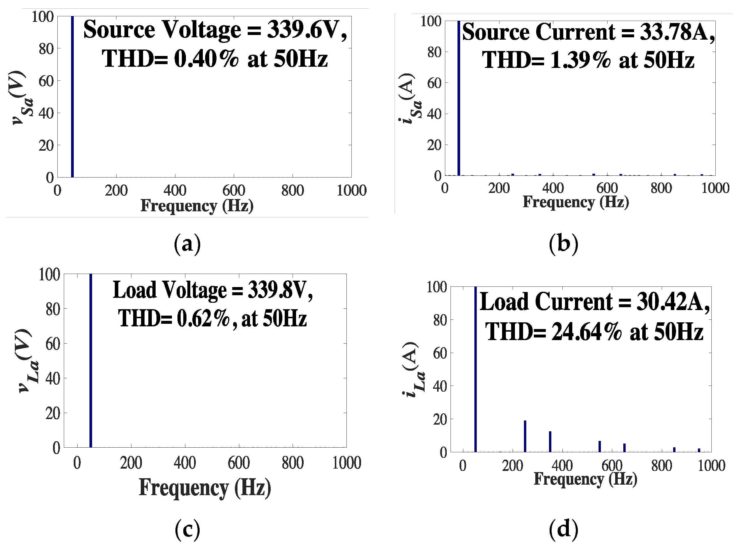
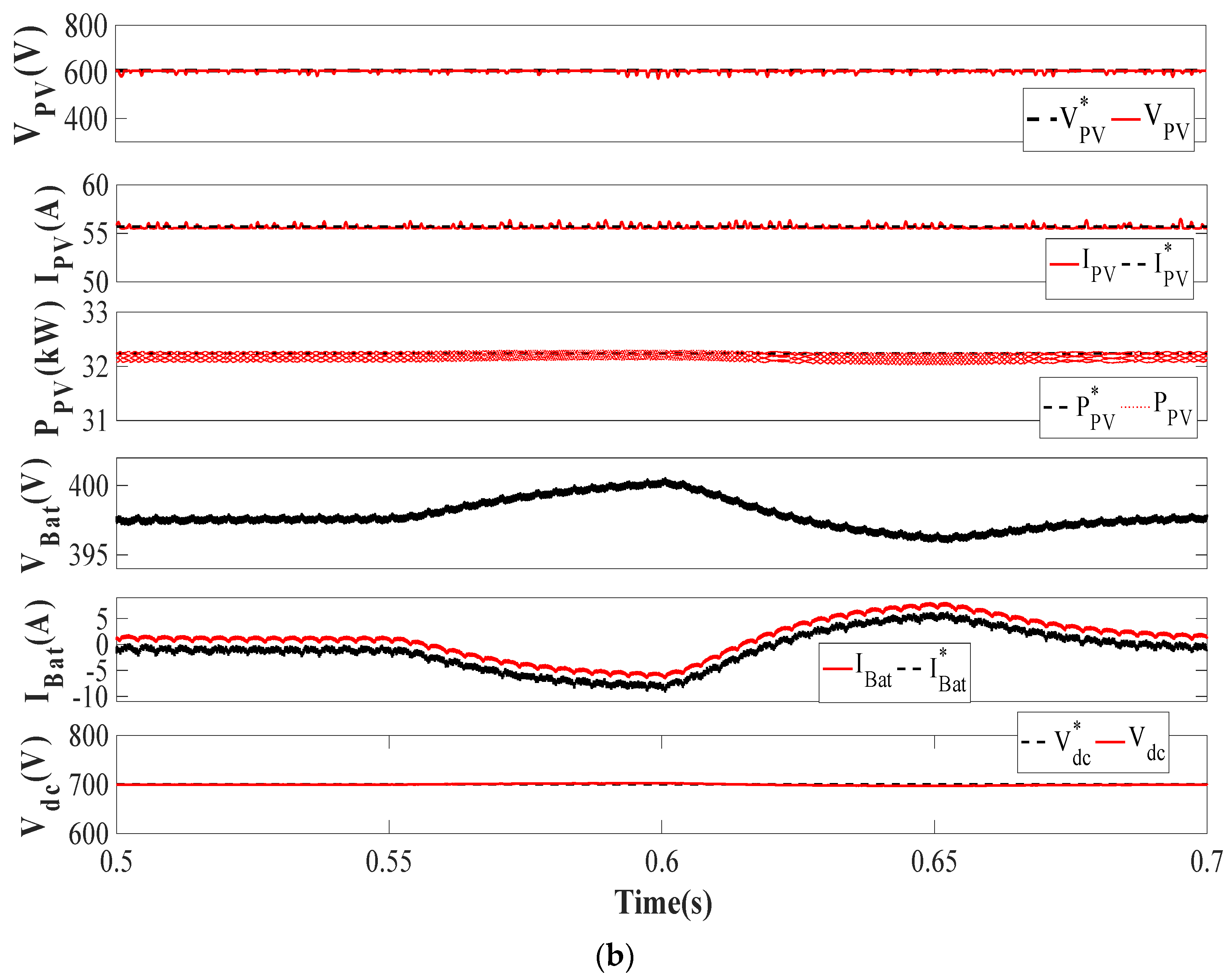
6.3. Steady-State Analysis

The steady-state is simulated by maintaining the solar irradiation level at 1000 W/m2. The total harmonics distortion (THD) of phase ‘a’ of grid voltage ( v S a ) , grid current ( i S a ) , load voltage ( v L a ) , and load current ( i L a ) are satisfactory as per IEEE519 standards are shown in Figure 10a–d. Table 4. presents the comparative THD analysis of v S a and i S a during steady-state with MOGHO, PSO, GA and without optimization technique. With the MOGHO algorithm the proposed system delivers comparatively minimum THD.

6.4. Irradiation Variation Analysis

The insolation level is reduced from 1000 W/m2 to 600 W/m2 at 0.15 s of simulation time. The grid voltages and currents ( v S a b c and i S a b c ) remain in phase opposition, but the i S a b c magnitude reduces with insolation level such as P g . The i S a b c follows its reference currents ( i S a b c * ) during the induced dynamic condition. The P g delivered to the grid reduces, as less power is being generated by the PV system while following its reference P g * . The power PV power ( P P V ) and battery collectively are sufficient enough to satisfy the load requirements. The phase ‘a’ of load current ( i L a ) and compensator current ( i C a ) remains in phase with each other. The Q g must be satisfied by the VSC itself leaving the sinusoidal nature of the source intact. The Q g follows the Q g * = 0 , which is the reference reactive power exchange from the grid as shown in Figure 11a. The PV voltage ( V P V ), current ( I P V ) and power ( P P V ) are also found following the reference PV voltage ( V PV * ) , current ( I PV * ) and power ( P PV * ) . The V P V settles down to 600 V after some variations with a boost converter, while I P V and P P V change accordingly with a reduced irradiation level. The battery voltage ( V B a t ) and current ( I B a t ) depict the battery’s charging and discharging rate. The I B A T follows its reference signal ( I Bat * ) . The V d c is maintained at the desired level of 700 V and keep matching with its reference DC link voltage ( V dc * ) is also shown in Figure 11b.

6.5. Load Unbalancing Analysis

The load unbalancing is simulated from 0.35 s to 0.45 s by removing the phase ‘a’ of the load. The i S a b c maintains the UPF with v S a b c while remaining 180 ° out of phase. The i S a b c exactly follows i S a b c * leading towards a stable system. During load unbalancing, only two phases of the load are connected to the system. Hence the load requirement reduces to 66% of the actual load requirement. The P g delivered to the grid increases during unbalanced load. The Q g exchange with grid remains zero in load unbalancing mode, as shown in Figure 12a. The V P V , I P V and P P V remain as it is with a fixed insolation level. The I B a t becomes more negative and follows I Bat * as more power is available for battery charging. The V B a t also increases as the rate of battery charging increases. The V d c is kept at the required level of 700 V, such as V dc * , as depicted in Figure 12b.

6.6. Specific Power Mode Analysis

The fixed or specified power mode is simulated from 0.55 s to 0.65 s of simulation time, where the system has to supply the pre-decided amount of power to the grid for handling the peak demand. The P g varies along with i S a b c as per the pre-decided grid demand. The i S a b c keep following its reference signals i S a b c * while maintaining the UPF in phase opposition to v S a b c . The i L a and i C a maintain the in-phase relation. The Q g is also held around zero while following its reference Q g * as shown in Figure 13a. The V P V , I P V and P P V shows no variation as the irradiation level is kept at 1000 W/m2. The I B a t and V B a t change according to load requirement or charging/discharging phase. The PV and battery are collectively managing the peak demand occurring on the grid. The V d c is also maintained at 700 V, as V d c * , as shown in Figure 13b.

6.7. Abnormal Grid Voltage Analysis

The grid voltage abnormality is simulated by changing the magnitude of v S a b c to 0.8 p.u. and 1.2 p.u. from 0.75 s to 0.85 s of simulation time. As the v S a b c changes i S a b c has to change to maintain the balance of power. The i C a and i L a remain in phase with each other. The P g changes abruptly with the abnormal grid voltage but settle down quickly. The Q g exchange with the grid is kept zero as Q g * as shown in Figure 14a. The V P V , I P V and P P V remain unchanged other than minor transients. The I B a t changes from charging to discharging mode as the grid voltage goes through sag and swell. The V d c is maintained at the desired level of 700 V as shown in Figure 14b.

6.8. Internal Control Signals Analysis

The internal control signals involving μ p a , i S a * ,   W avg ,   W PV , and W sp are presented in Figure 15. The μ p a remains sinusoidal with unity magnitude throughout the operation. The i S a * magnitude changes under the induced diverse dynamic conditions. The W avg reduces during load unbalancing, as the weight signal of phase ‘a’ diminishes to zero. The W avg also varies during abnormal grid voltage as weight signals of each phase changes as per voltage sag and swell. The W PV tries to balance the active power flow through the DC link. The W sp varies as a function of W avg and W PV . Figure 16 shows the W avg variations with proposed AKWSOMCC, MCC, LMF and LMS control during diverse dynamic conditions. The AKWSOMCC control delivers W avg with the minimum steady-state and dynamic state error. The convergence speed of the proposed control is also comparable with LMS and LMF controls. As the W avg is having reduced ripples with the proposed control, which offers better VSC performance and reduced overall losses in the system.

7. Future Research Direction

The authors wish to extend the presented work by utilizing the optimization techniques for reducing the switching losses of the VSC and boost converter and validating it through hardware implementation.

8. Conclusions

In the 3P-3W grid-tied dual-stage PV-battery storage system, a nature-inspired meta-heuristic technique named MOGHO algorithm has been implemented for optimization of modulation factor for VSS-InC MPPT algorithm and PI controller gains for DC bus regulation. The VSS-InC with the optimized modulation factor offers faster and accurate maximum power point (MPP) tracking with reduced oscillations across MPP. With optimization implemented, the settling time of PV voltage and current have been greatly reduced from 13.2 ms to 2.1 ms just after sudden irradiation change along with oscillations. The boost converter efficiency has also swollen from 98.82% to 99.82% with optimized VSS-InC MPPT. The MOGHO tuned DC bus optimization offers enhanced system’s stability during dynamic conditions and produces an accurate loss component of current. The accurate loss component of current further improves the AKWSOMCC based VSC control capability by extracting a precise fundamental component of current. The V dc rise time and settling time have been lessened to 0.8 ms and 3 ms with MOGHO in comparison with PSO, GA and non-optimized DC bus. Moreover, with MOGHO the steady-state and dynamic state error of V dc are obtained as low as 0.061% and 0.2% respectively. Due to the combined effect of optimized MPPT and DC bus, the VSC efficiency is grown from 98.47% to 99.23% and collective conduction losses of the boost converter and VSC have also been reduced from 875 W to 308 W. The parameter optimization is carried out on an offline basis, considering diverse dynamic conditions, to obtain the desired system’s performance during online operation without slowing down the convergence speed of the system. The AKWSOMCC based VSC control, with adaptive kernel width, acts as a higher-order filter against both Gaussian and non-Gaussian noises, without affecting the convergence speed. The AKWSOMCC control performs multi-functional operations, i.e., harmonics elimination, load balancing, reactive power compensation and active power balancing during dynamic conditions. The presented system operates satisfactorily as per IEEE 519 standards.

Author Contributions

The presented work was developed by the following contributions: conceptualization, methodology: M.C. and H.M.; software, formal analysis, research, writing—original draft preparation: I.H. and A.A.; writing—review and editing, and supervising: H.M.; writing—review and editing, and supervising: F.P.G.M. All authors have read and agreed to the published version of the manuscript.

Funding

The work reported herewith has been supported by Intelligent Prognostic Private Limited, Delhi India (Project Number: XX-02), and J&K Science Technology and Innovation Council, Department of Science and Technology, Jammu & Kashmir (JKST&IC/75/2020).

Conflicts of Interest

The authors declare no conflict of interest.

Nomenclature

DDuty cycle
Δ D Duty cycle perturbation
δ Scaling factor
K p , K i PI controller gains
i Loss Loss component of current (A)
V t Voltage magnitude (V)
V P V PV voltage (V)
V P V * Reference PV voltage (V)
I P V PV current (A)
I P V * Reference PV current (A)
P P V PV power (kW)
P P V * Reference PV power (kW)
V d c DC bus voltage (V)
V d c * Reference DC bus voltage (V)
P i Fitness function
S i Social interaction term
S ( r ) Social force
G i Gravity term
gGravitational constant
A i Wind advection term
e w ^ Unit vector in wind direction
e g ^ Unit vector towards earth’s centre
c = c 1 = c 2 Comfort zone coefficient
t max Maximum iteration
r 1 , r 2 , r 3 Random numbers between [1, 0]
fAttraction intensity
lAttraction length scale
d i j Distance between i t h and j t h grasshopper
I Bat Battery current (A)
I Bat * Reference battery current (A)
I Bat max Maximum battery current (A)
V Bat Battery voltage (V)
σ n Adaptive kernel width
σ 0 Fixed kernel width
e n x ( x = a , b , c ) Error signals
μ p x ( x = a , b , c ) In-phase components
W Px ( x = a , b , c ) Weight signals
W avg Average weight signals
W PV Feed forward term
W SP Overall weight
W SP fix W S P during fixed power mode
v S a b c Source voltage (V)
i S a b c Source current (A)
i S x * ( x = a , b , c ) Reference source current (A)
i S x f i x * ( x = a , b , c ) Fixed power mode reference currents (A)
v S a Source voltage phase ‘a’ (V)
i S a Source current phase ‘a’ (A)
v L a Load voltage phase ‘a’ (V)
i L a Load current phase ‘a’ (A)
P g Power delivered to grid (W)
P g * Reference P g
Q g Reactive power delivered to grid (W)
Q g * Reference Q g
u b j ,   l b j Upper and lower bound
N No. of search agents
3P-3WThree-phase three-wire
ANNArtificial neural network
MOSHOMulti-objective grasshopper optimization
VSCVoltage source converter
AKWSOMCCAdaptive kernel width sixth order maximum correntropy criteria
InCIncremental conductance
VSS-InCVariable step-size InC
PIProportional integral
ISE-1Integral Square Error-1
ISE-2Integral Square Error-2
Obj-1First objective function
Obj-2Second objective function
SISwarm intelligence
GAGenetic algorithm
PSOParticle swarm optimization
PVPhotovoltaic
P&OPerturb and observe
VSS-P&OVariable step-size P&O
MPPTMaximum power point tracking
MPPMaximum power point
MOTMeta-heuristic optimization technique
SSOSalp swarm optimization
GNDOGeneralized normal distribution optimization
WOAWhale optimization algorithm
DRLDeep reinforcement learning
SACSoft actor-critic
DDPGDeep reinforcement polocy gradient
EADDPGExpert assiatent DDPG
SRFSynchronous reference frame
PBTPower balance theory
IARCInstantaneous active reactive control
AARCAverage active reactive control
BPSCBalanced positive sequence compensation
PNSCPositive negative sequence compensation
KFCKalman filter based controls
STStockwell transformation
LMSLeast mean square
LMFLeast mean fourth
MCCMaximum correntropy criteria
HCLMSHyperbolic cosine LMS
HTFHyperbolic tangent function
ANF-LMSAdaptive neuro-fuzzy LMS
ZALMFZero attracting LMF
NMCCNormalized MCC
FFPFixed forward prediction
PCCPoint of common coupling
MSEMean square error
THDTotal harmonics distortion

Appendix A

PV array: Kyocera GT200 module, 23 and 7 panels connected in series and parallel, V pv = 604.9 V, I pv = 53.32 A & P pv   = 32.3 kW; buck-boost converters parameters, L i = 4 mH; boost converter parameters, L b = 3.11 mH; optimized PI gains and δ :- with GA, K P = 0.82, K i = 0.38, δ = 0.00036; with PSO, K P = 0.94, K i = 0.71, δ = 0.000049; with MOSHO, K P = 1.22, K i = 0.89, δ = 0.00071; initial values K P d c = 1, K i d c = 0 and δ = 0.0001; pre-decided kernel width, σ 0 = 10; battery parameters, V B a t = 400, I Bat = 14 Ah, battery capacity = 5.6 kWh; MOSHO parameters, c m a x   = 1 and c m i n   = 0.000001, t m a x   = 50, population size = 50, lower and upper bounds for K P = [0, 3], K i d c = [0, 3] and δ   = [0, 0.1]; sampling time, T s = 10 µs.

References

  1. Alluhaybi, K.; Member, S.; Batarseh, I. Comprehensive Review and Comparison of Microinverters. IEEE J. Emerg. Sel. Top. Power Electron. 2019, 8, 1310–1329. [Google Scholar] [CrossRef]
  2. Gandhi, O.; Kumar, D.S.; Rodríguez-Gallegos, C.D.; Srinivasan, D. Review of power system impacts at high PV penetration Part I: Factors limiting PV penetration. Sol. Energy 2020, 210, 181–201. [Google Scholar] [CrossRef]
  3. Kumar, D.S.; Gandhi, O.; Rodríguez-Gallegos, C.D.; Srinivasan, D. Review of power system impacts at high PV penetration Part II: Potential solutions and the way forward. Sol. Energy 2020, 210, 202–221. [Google Scholar] [CrossRef]
  4. Mao, M.; Cui, L.; Zhang, Q.; Guo, K.; Zhou, L.; Huang, H. Classification and summarization of solar photovoltaic MPPT techniques: A review based on traditional and intelligent control strategies. Energy Rep. 2020, 6, 1312–1327. [Google Scholar] [CrossRef]
  5. Karami, N.; Moubayed, N.; Outbib, R. General review and classification of different MPPT Techniques. Renew. Sustain. Energy Rev. 2017, 68, 1–18. [Google Scholar] [CrossRef]
  6. Motahhir, S.; El Hammoumi, A.; El Ghzizal, A. The most used MPPT algorithms: Review and the suitable low-cost embedded board for each algorithm. J. Clean. Prod. 2020, 246, 118983. [Google Scholar] [CrossRef]
  7. Messalti, S.; Harrag, A.; Loukriz, A. A new variable step size neural networks MPPT controller: Review, simulation and hardware implementation. Renew. Sustain. Energy Rev. 2017, 68, 221–233. [Google Scholar] [CrossRef]
  8. Loukriz, A.; Haddadi, M.; Messalti, S. Simulation and experimental design of a new advanced variable step size Incremental Conductance MPPT algorithm for PV systems. ISA Trans. 2016, 62, 30–38. [Google Scholar] [CrossRef]
  9. Mei, Q.; Shan, M.; Liu, L.; Guerrero, J.M. A novel improved variable step-size incremental-resistance MPPT method for PV systems. IEEE Trans. Ind. Electron. 2011, 58, 2427–2434. [Google Scholar] [CrossRef]
  10. Bhattacharyya, S.; Kumar P, D.S.; Samanta, S.; Mishra, S. Steady output and fast tracking MPPT (SOFT-MPPT) for P&O and InC algorithms. IEEE Trans. Sustain. Energy 2021, 12, 293–302. [Google Scholar] [CrossRef]
  11. Pandey, A.; Dasgupta, N.; Mukerjee, A.K. High-performance algorithms for drift avoidance and fast tracking in solar MPPT system. IEEE Trans. Energy Convers. 2008, 23, 681–689. [Google Scholar] [CrossRef] [Green Version]
  12. Jiang, Y.; Qahouq, J.A.A.; Haskew, T.A. Adaptive step size with adaptive-perturbation-frequency digital MPPT controller for a single-sensor photovoltaic solar system. IEEE Trans. Power Electron. 2013, 28, 3195–3205. [Google Scholar] [CrossRef]
  13. Chen, Y.T.; Lai, Z.H.; Liang, R.H. A novel auto-scaling variable step-size MPPT method for a PV system. Sol. Energy 2014, 102, 247–256. [Google Scholar] [CrossRef]
  14. Liu, F.; Duan, S.; Liu, F.; Liu, B.; Kang, Y. A variable step size INC MPPT method for PV systems. IEEE Trans. Ind. Electron. 2008, 55, 2622–2628. [Google Scholar] [CrossRef] [Green Version]
  15. Ahmed, J.; Salam, Z. A Modified P and O Maximum Power Point Tracking Method with Reduced Steady-State Oscillation and Improved Tracking Efficiency. IEEE Trans. Sustain. Energy 2016, 7, 1506–1515. [Google Scholar] [CrossRef]
  16. Kumar, N.; Hussain, I.; Singh, B.; Panigrahi, B.K. Self-Adaptive Incremental Conductance Algorithm for Swift and Ripple-Free Maximum Power Harvesting from PV Array. IEEE Trans. Ind. Inform. 2018, 14, 2031–2041. [Google Scholar] [CrossRef]
  17. Mansoor, M.; Mirza, A.F.; Ling, Q.; Javed, M.Y. Novel Grass Hopper optimization based MPPT of PV systems for complex partial shading conditions. Sol. Energy 2020, 198, 499–518. [Google Scholar] [CrossRef]
  18. Jumani, T.A.; Mustafa, M.W.; Alghamdi, A.S.; Rasid, M.M.; Alamgir, A.; Awan, A.B. Swarm Intelligence-Based Optimization Techniques for Dynamic Response and Power Quality Enhancement of AC Microgrids: A Comprehensive Review. IEEE Access 2020, 8, 75986–76001. [Google Scholar] [CrossRef]
  19. Mishra, S.; Ray, P.K. Power Quality Improvement Using Photovoltaic Fed DSTATCOM Based on JAYA Optimization. IEEE Trans. Sustain. Energy 2016, 7, 1672–1680. [Google Scholar] [CrossRef]
  20. Chankaya, M.; Hussain, I.; Ahmad, A.; Khan, I.; Muyeen, S.M. Nyström Minimum Kernel Risk-Sensitive Loss Based Seamless Control of Grid-Tied PV-Hybrid Energy Storage System. Energies 2021, 14, 1356. [Google Scholar] [CrossRef]
  21. Chankaya, M.; Hussain, I.; Ahmad, A.; Malik, H.; Márquez, F.P.G. Generalized Normal Distribution Algorithm-Based Control of 3-Phase 4-Wire Grid-Tied PV-Hybrid Energy Storage System. Energies 2021, 14, 4355. [Google Scholar] [CrossRef]
  22. Mosaad, M.I.; Ramadan, H.S.M.; Aljohani, M.; El-Naggar, M.F.; Ghoneim, S.S.M. Near-Optimal PI Controllers of STATCOM for Efficient Hybrid Renewable Power System. IEEE Access 2021, 9, 34119–34130. [Google Scholar] [CrossRef]
  23. Wu, J.; Wei, Z.; Li, W.; Wang, Y.; Li, Y.; Sauer, D.U. Battery Thermal-and Health-Constrained Energy Management for Hybrid Electric Bus Based on Soft Actor-Critic DRL Algorithm. IEEE Trans. Ind. Inform. 2021, 17, 3751–3761. [Google Scholar] [CrossRef]
  24. Wei, Z.; Quan, Z.; Wu, J.; Li, Y.; Pou, J.; Zhong, H. Deep Deterministic Policy Gradient-DRL Enabled Multiphysics-Constrained Fast Charging of Lithium-Ion Battery. IEEE Trans. Ind. Electron 2021, in press. [Google Scholar] [CrossRef]
  25. Wu, J.; Wei, Z.; Liu, K.; Quan, Z.; Li, Y. Battery-Involved Energy Management for Hybrid Electric Bus Based on Expert-Assistance Deep Deterministic Policy Gradient Algorithm. IEEE Trans. Veh. Technol. 2020, 69, 12786–12796. [Google Scholar] [CrossRef]
  26. Bhim, S.; Chandra, A.; Al-haddad, K. Power Quality Problems and Mitigation Techniques-Wiley Online Library. Available online: http://onlinelibrary.wiley.com/book/10.1002/9781118922064 (accessed on 1 January 2015).
  27. Abbassi, R.; Marrouchi, S.; Saidi, S.; Abbassi, A.; Chebbi, S. Optimal energy management strategy and novel control approach for DPGSs under unbalanced grid faults. J. Circuits Syst. Comput. 2019, 28, 1950057. [Google Scholar] [CrossRef]
  28. Shen, M.; Xiong, K.; Wang, S. Multikernel adaptive filtering based on random features approximation. Signal Process. 2020, 176, 107712. [Google Scholar] [CrossRef]
  29. Kumar, R.; Singh, B.; Kumar, R.; Marwaha, S. Recognition of underlying causes of power quality disturbances using stockwell transform. IEEE Trans. Instrum. Meas. 2020, 69, 2798–2807. [Google Scholar] [CrossRef]
  30. Agarwal, R.K.; Hussain, I.; Singh, B. Application of LMS-based NN structure for power quality enhancement in a distribution network under abnormal conditions. IEEE Trans. Neural Netw. Learn. Syst. 2018, 29, 1598–1607. [Google Scholar] [CrossRef] [PubMed]
  31. Agarwal, R.K.; Hussain, I.; Singh, B. LMF-based control algorithm for single stage three-phase grid integrated solar PV system. IEEE Trans. Sustain. Energy 2016, 7, 1379–1387. [Google Scholar] [CrossRef]
  32. Modi, G.; Kumar, S.; Singh, B. A Maximum Correntropy Criteria Based Adaptive Algorithm for an Improved Power Quality SPV System. In Proceedings of the 8th IEEE Power India International Conference (PIICON), Kurukshetra, India, 10–12 December 2018; pp. 1–6. [Google Scholar] [CrossRef]
  33. Kumar, A.; Seema; Singh, B.; Jain, R. Double stage grid-tied solar PV system using HC-LMS control. In Proceedings of the 2020-9th IEEE Power India International Conference (PIICON), Sonepat, India, 28 February–1 March 2020; pp. 3–8. [Google Scholar] [CrossRef]
  34. Jain, V.; Hussain, I.; Singh, B. A HTF-Based Higher-Order Adaptive Control of Single-Stage Grid-Interfaced PV System. IEEE Trans. Ind. Appl. 2019, 55, 1873–1881. [Google Scholar] [CrossRef]
  35. Srinivas, M.; Hussain, I.; Singh, B. Combined LMS–LMF-Based Control Algorithm of DSTATCOM for Power Quality Enhancement in Distribution System. IEEE Trans. Ind. Electron. 2016, 63, 4160–4168. [Google Scholar] [CrossRef]
  36. Badoni, M.; Singh, A.; Singh, B. Adaptive Neurofuzzy Inference System Least-Mean-Square-Based Control Algorithm for DSTATCOM. IEEE Trans. Ind. Inform. 2016, 12, 483–492. [Google Scholar] [CrossRef]
  37. Singh, A.K.; Hussain, I.; Singh, B. Double-Stage Three-Phase Grid-Integrated Solar PV System With Fast Zero Attracting Normalized Least Mean Fourth Based Adaptive Control. IEEE Trans. Ind. Electron. 2018, 65, 3921–3931. [Google Scholar] [CrossRef]
  38. Chankaya, M.; Hussain, I.; Ahmad, A. Seamless control of grid-tied PV-Hybrid Energy Storage System. Int. J. Emerg. Electr. Power Syst. 2021, 22, 000010151520210090. [Google Scholar] [CrossRef]
  39. Jain, V.; Hussain, I.; Singh, B. A FFP Based Adaptive Control of SPV System Tied to Weak Grid. IEEE Trans. Ind. Appl. 2018, 54, 3112–3121. [Google Scholar] [CrossRef]
  40. Chankaya, M.; Ahmad, A.; Hussain, I. Adaptive Kernel Width Maximum Correntropy based VSC control of grid-tied PV-BESS System. In Proceedings of the 2021 1st International Conference on Power Electronics and Energy (ICPEE), Shillong, Meghalaya, India, 5–7 March 2021; pp. 1–6. [Google Scholar]
Figure 1. Proposed topology.
Electronics 10 02770 g001
Figure 2. Research methodology.
Electronics 10 02770 g002
Figure 3. MOGHO flowchart.
Electronics 10 02770 g003
Figure 4. MOGHO algorithm based VSS-InC MPPT.
Electronics 10 02770 g004
Figure 5. Variable and fixed step size MPPT operation.
Electronics 10 02770 g005
Figure 6. Bi-directional converter and DC bus voltage control.
Electronics 10 02770 g006
Figure 7. AKWSOMCC based VSC control.
Electronics 10 02770 g007
Figure 8. (ad) System performance with optimized δ VSS-InC during steady-state and irradiation variation of (a)   V PV (b) I PV (c) P PV (d) D.
Electronics 10 02770 g008
Figure 9. (a,b) Optimized V dc analysis during dynamic conditions. (b) Optimized i L o s s current analysis during dynamic conditions system.
Electronics 10 02770 g009
Figure 10. (ad) THD analysis of v S a , i S a , v L a   and   i L a .
Electronics 10 02770 g010
Figure 11. Irradiation variation analysis of (a) v s a b c , i s a b c , i C a , i L a , P g & Q g (b) V PV , I PV , P PV , V Bat , I Bat , &   V dc .
Electronics 10 02770 g011aElectronics 10 02770 g011b
Figure 12. Load unbalancing analysis of (a) v s a b c , i s a b c , i C a , i L a , P g & Q g (b) V PV , I PV , P PV , V Bat , I Bat , &   V dc .
Electronics 10 02770 g012
Figure 13. Specific power mode analysis of (a) v s a b c , i s a b c , i C a , i L a , P g & Q g (b) V PV , I PV , P PV , V Bat , I Bat , &   V dc .
Electronics 10 02770 g013aElectronics 10 02770 g013b
Figure 14. Abnormal grid voltage variation analysis of (a) v s a b c , i s a b c , i C a , i L a , P g & Q g (b) V PV , I PV , P PV , V Bat , I Bat , &   V dc .
Electronics 10 02770 g014
Figure 15. Internal control signal analysis of μ p a , i S a * ,   W avg , W PV , and W sp .
Electronics 10 02770 g015
Figure 16. Average weights Wavg with AKWSOMCC, MCC, LMF and LMS algorithm.
Electronics 10 02770 g016
Table 1. MPPT, boost converter and VSC performance analysis during sudden irradiation level change.
ParametersMOGHOPSOGAWith Initially Selected δ
V PV settling time2.11 ms3.04 ms3.75 ms12.50 ms
I PV settling time2.12 ms3.02 ms3.74 ms13.25 ms
Boost Converter Efficiency99.82%99.61%99.42%98.82%
VSC Efficiency99.23%99.11%98.79%98.47%
Total dual-stage Losses (W)308 W414 W580 W875 W
Table 2. Optimized design variables ( k p , k i and δ ).
Decision VariablesMOGHOPSOGAWithout
Optimization
k p 1.220.940.821
k i 0.890.710.380
δ 0.000710.000490.000360.0001
Table 3. Comparative performance of DC bus.
ParametersMOGHOPSOGAWithout Optimization
Computational burdenHighModerateModerateNone
Rise time0.8 ms0.85 ms1.3 ms1.78 ms
Settling time3 ms6 ms6.5 ms15 ms
Steady-state error0.061%0.064%0.143%0.121%
Dynamic-state error (Irradiation change)1.800%2.457%2.943%3.929%
Dynamic-state error (Load unbalancing)0.200%0.571%0.671%1.857%
Dynamic-state error (Fixed power mode)0.829%1.243%1.643%2.571%
Dynamic-state error (Abnormal grid voltage)1.686%2.200%2.586%3.486%
Transient-state error1.229%1.264%1.886%2.714%
Table 4. THD comparison of v S a , i S a , v L a , i L a with AKWSOMCC based VSC controls.
ParametersMOGHOPSOGAWithout Optimization
vSa0.40%0.44%0.43%0.49%
iSa1.39%1.89%2.37%2.82%
vLa0.62%0.61%0.62%0.62%
iLa24.64%24.64%24.64%24.64%
Publisher’s Note: MDPI stays neutral with regard to jurisdictional claims in published maps and institutional affiliations.

