1. Introduction
The history of architecture and architectural drawings is so long that it cannot be separated from human culture. However, until the second half of the 20th century, when the spread of PCs made the use of computer-aided design (CAD) software [
1] possible, architectural drawings were completed on paper and archived only on paper or as scanned raster images. Even today, when CAD is widely used, CAD data are employed only for professional purposes, and most architectural drawings are used and distributed in an image format. Because there is a limit to the information that can be checked in these 2D images, there has always been a need for transforming them into vector data and 3D shape models. However, much time and effort is required to manually create numerous images as 3D vector data.
For example, we can quickly identify room extents or areas, door layouts, and shapes of drawings. Recently, some large-scale buildings use building information modeling (BIM) data for 3D building object information to systematically manage the life cycle, but most buildings do not use it for reasons, such as cost or construction period. This study can be the basis for BIM data [
2]. Ultimately, this study can be utilized as a basic research for automatically generating architectural drawings using artificial intelligence.
Converting raster images into vector-based drawings is a challenge for researchers, and, accordingly, numerous studies have been conducted. An architectural plan consists of various structural architectural objects and auxiliary information objects, such as walls, doors/windows, rooms, furniture, materials, door/window rotation radius, dimensions, and various texts. Since an architectural plan represents the shape of a horizontal section at a specific height, its three-dimensional shape must also be predicted, for example, a wall that is covered by the door/window image. These various objects must be classified and extracted, and their sizes should be meaningful.
Most of the problems tackled by existing studies were mainly solved through heuristic-based algorithms [
3,
4,
5,
6,
7,
8,
9,
10,
11,
12,
13,
14,
15], and the applied drawings were kept in a small amount of samples. In recent years, deep learning has been used to extract objects from images, and the accuracy of the objects has been improved [
16,
17,
18,
19,
20,
21]. However, to accomplish this, much effort was required to prepare a large amount of training data and for annotating a floorplan dataset [
22].
In order to overcome this limitation, we conducted learning with only a small amount of training data (30 floor plan images), and proposed an end-to-end 3DPlanNet Ensemble model that incorporates a complementary rule-based heuristic method. Despite the small amount of training data, a wall was created with an accuracy of 95% or more, and the 3D object was automatically created with an accuracy close to that of a previous study [
16]. Additionally, using the drawing’s area information, a 2D drawing without scale was created with an accuracy of 97% or more. As a result of this study, about 110,000 drawing images were converted into 3D vector data. In order to service to the actual system [
23], the insufficient parts were corrected manually, and a questionnaire survey on the performance of the 3DPlanNet Ensemble methods was also conducted with the corresponding modifiers.
2. Related Work
The task of converting 2D architectural drawing images into vector data has a long history in the field of pattern recognition. For example, many studies have analyzed image drawings using various heuristic algorithms, such as Hough transform, image vectorization, and generic methods [
3,
4,
6,
7,
8,
9,
10,
11,
12,
13]. In [
5,
14,
15], architectural semantic information was used with heuristics to convert AutoCAD 2D vector data into 3D models. The research in [
24,
25,
26,
27,
28,
29] was conducted to generate and analyze 3D models and drawings directly from data captured by 3D scans. However, their results show limitations in performance, such as accuracy and scalability, and could not be applied to the creation of a large number of 3D models.
Recently, there have been studies [
16,
17,
18,
19,
20,
21,
30,
31] that recognize 2D architectural plan images using deep learning based on data. For example, [
17,
18,
19,
20,
21,
30,
31] analyzed image drawings using graph neural network (GNN) [
17,
18], generative adversarial network (GAN) [
17,
20], convolutional neural network (CNN) [
19,
21], global convolutional network (GCN) [
30], and fully convolutional network (FCN) [
31]. One study [
16] showed the results of generating 3D models with high accuracy by extracting junction data through a convolutional neural network (CNN) modified with ResNet-152. A junction layer and a primitive layer were created through the junction data to create a wall and a closed curve. However, the method of creating a wall through junction data reduces the accuracy of the wall’s creation. For example, even in a location where there is no wall, a faulty wall can be created through two collinear junction points. In order to solve this limitation, we focused on recognizing the wall line itself, not the junction data, and we were able to create walls with high accuracy.
Although a large amount of training data are required for data-based learning, the reality is that there are little training data. For deep learning, training/test data (870 [
16], 319 [
30], 500 [
31]) were directly generated in the previous studies, but a great deal of time and effort was required. To solve this problem, we trained with 30 data (floor plan images) and used ensemble methods incorporating rule-based heuristic methods. As a result of this study, 110,000 3D models with a wall accuracy of more than 95% were produced and are currently being used as a web service [
23].
3. Methods
Converting raster images into vector-based drawings is a challenge for researchers, and, consequently, numerous studies have been conducted. Architectural drawings consist of various structural architectural objects and auxiliary information objects, such as walls, doors, windows, rooms, furniture, material, door/window rotation radius, dimensions, and various text. Recently, several studies [
16,
17,
18,
19,
20,
21,
30,
31] have recognized 2D architectural drawing images using deep learning based on data, but a large amount of learning data was required for learning. To solve this problem, we propose 3DPlanNet Ensemble methods that combine data-based methods with 30 pieces of learning data and rule-based heuristic methods.
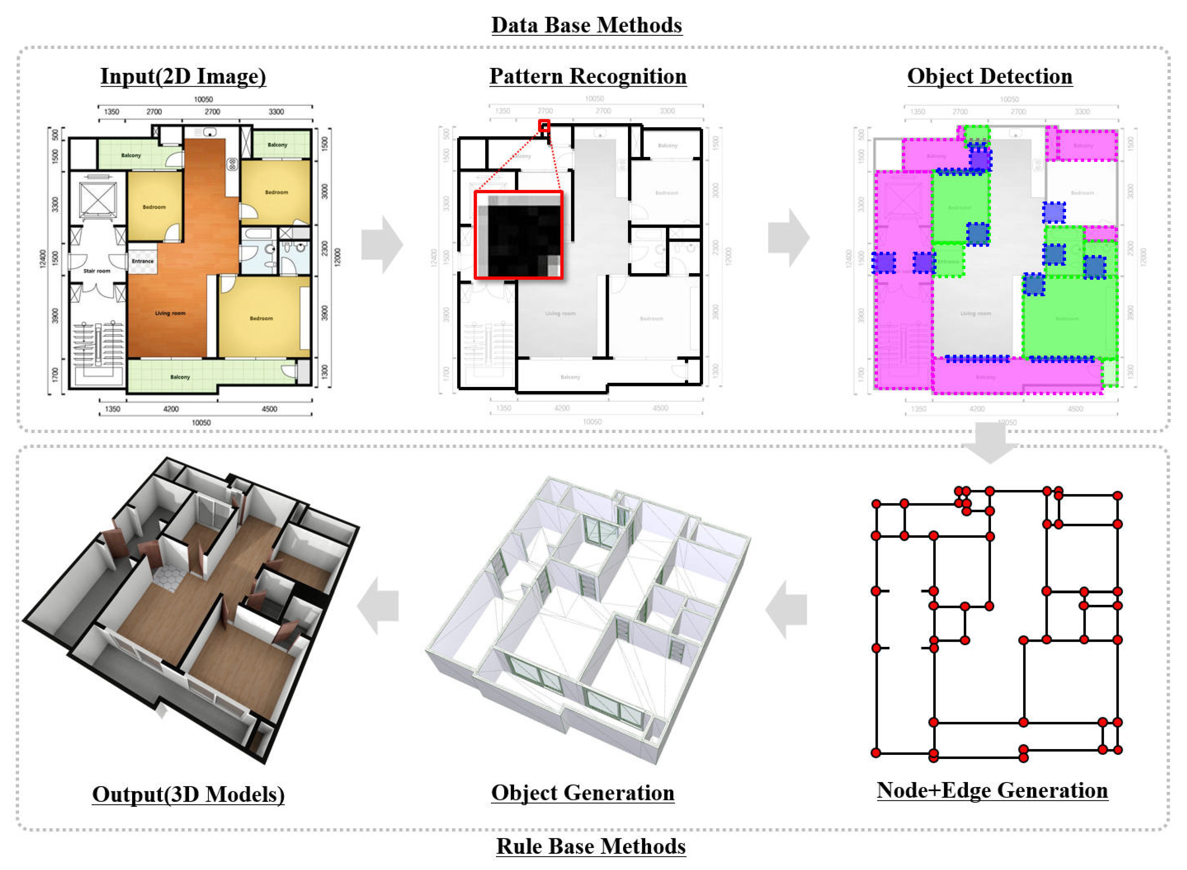
As shown in
Figure 1, the 3DPlanNet is composed of pattern recognition, object detection data (learning) based methods, node + edge generation, and object generation rule (heuristic) based methods. It can generate 3D vector models through sequential end-to-end steps. Each step is described in more detail below.
3.1. Pattern Recognition
The task of converting 2D architectural plan images into vector data has a long history in the field of pattern recognition. For such conversions, the task of recognizing walls is the most important and difficult part of the research. In an architectural drawing, the division of the space and the layout of the doors/windows are all made through the composition of the wall. Since wall patterns are diverse, it becomes more difficult to determine the wall due to the shape of the doors/windows. We decided that it would be much easier to identify the wall by excluding the door/window area. Accordingly, it was possible to recognize the wall simply by learning it without the door/window area using a logistic regression model in units of a certain area (5 × 5 pixels).
Just as in [
30], which restored the wall thickness using the moving kernel method, we restored the wall center using the same method. However, unlike [
30], which determined whether the wall was heuristic, we determined the wall center point by discriminating the logistic regression learning result for a certain area (5 × 5 pixels). In this study, focusing on the point that most architectural drawings consist of horizontal/vertical walls, only horizontal/vertical walls, excluding any diagonal walls, were recognized. As shown in
Figure 2, when the wall was identified through the kernel method moving from left to right and the kernel method of 5 × 5 pixels moving from top to bottom, the center point of 5 × 5 pixels was restored to the wall center. Later, a vector-based wall line was created through an image vectorization technique based on the pixels stored in the node + edge generation stage.
Section 3.4 will explain the node + edge generation in more detail.
As shown in
Figure 3, the finally restored wall center line was able to recognize the center line in almost all the wall areas except for the door/window area. In the drawing image, several parallel center lines were restored for walls with a wall thickness of 5 pixels or more, but they were corrected in the node + edge generation step.
3.2. Object Detection
In addition to wall information, 2D architectural drawings include various information, including doors, windows, rooms, furniture, materials, dimensions, and text. Naturally, how accurately the information can be extracted greatly affects the performance of the 3D vector models transformation. In the wall pattern recognition step, since recognition was performed excluding the door/window area, we needed to recognize the door/window area in order to increase accuracy. Using TensorFlow object detection API [
32], we classified each object into wall junction, opening, and room, and then performed object detection.
Wall Junction Detection. In order to extract the wall junction from the image, we divided The wall junction into 4 types I (w2), L (w1), T (w3), and X (w4), as in [
16], and each type, except for X (w4), was divided into 4 types (−1, −2, −3, −4). It was then classified into a total of 13 types (
Figure 4). In order to minimize the indirection of other types of images, the training data area of the wall junction were minimized to less than 40 pixels, and the wall was planned to be connected through the extracted junction data. However, as we will discuss again in
Section 4. Experiments, the accuracy of detection was low, so we had to exclude Wall Junction Detection from the actual experiment.
Openings (door/window) Detection. The shapes of the doors/windows are divided into a hinged type and a sliding type. In architectural drawings, the door is generally expressed as a hinged type (d1/d2/d4), and the window is expressed as a sliding type (d3) (
Figure 5). Exceptionally, sliding doors can be used in architectural drawings, but they cannot be distinguished in the image. We extracted information about the type, location, size, and direction of the sliding door through detection.
Room Detection. There are various room shapes, even for rooms having the same purpose, making detection very difficult. However, room types were essential information to improve the accuracy and to understand the use of space in the rule-based node + edge generation stage. The space is divided into 8 types: r1 (bedroom), r2 (restroom), r3 (entrance), r4 (balcony), r5 (stairs room), r6 (closet), r7 (duct), and r8 (living room) (
Figure 6). Since the wall line was not directly generated through the room detection information, an error of several pixels was allowed, and it was only used to determine the purpose and location of the space.
3.3. Node/Edge Generation
In this step, nodes and edges are created through information analyzed based on data so far. Nodes and edges are created as wall junctions and walls in the subsequent object generation stage. In order to increase the accuracy, the wall center information restored in the pattern recognition step and the opening data/room data extracted in the object detection step were used. The restored wall center information was converted into a vector line through an image vectorization technique based on the stored pixels. In the node + edge generation step, a wall with high accuracy was created with the following generation rules.
The restored wall center information was converted into a vector line through a image vectorization technique based on the stored pixels. In the Node/Edge Generation step, a wall with high accuracy was created with the following generation rules.
Generation Rule: In order to correctly create node + edge, the following rules are basically proposed (
Figure 7):
Orthogonality: All edges are composed of horizontal/vertical walls only. Drawings with diagonal lines are excluded from this study;
Substitution: The area from which the opening object (door/window) is extracted is replaced with a wall, and walls that are separated from each other are connected. Even if the walls that are separated from each other are not in a straight line, they are connected within the allowable distance (3 pixels);
Duplication: Lines overlapping parallel within a certain distance (5 pixels) of the wall are deleted, leaving only the longest wall. If they are arranged alternately, the wall is extended to the longest length;
Chamfer: According to the rule that the walls are all connected by a closed curve, a shape that is slightly separated is chamfered in a right angle shape;
Merge/Extension: Several shortly separated lines on a straight line are merged into one line and extended if there is no other intersecting line.
Through this generation rule, an edge (wall) was created, and a node (wall junction) was created at a location where the edge ends or crosses (
Figure 1).
3.4. Object Generation
Object generation is the final step in generating 3D models in the form of 3D mesh objects after the node + edge information is generated. In order to create a more realistic shape of the walls, doors, windows, floor, and ceiling, we created an object as a face composed of a solid shape using the constructive solid geometry (CSG) algorithm. Object creation was performed according to the following procedure. The floor/ceiling were created by classifying the types for each purpose by using room detection information and a heuristic algorithm (
Figure 1).
Wall/Wall Junction: The wall is made of 6-sided boxes of a certain width (150 mm) and height (2400 mm), and each wall is created as an object separated by wall junctions;
Opening (Door/Window): First, a hole is made in the wall where the door/window is placed using a CSG algorithm, and then a pre-modeled door/window object is placed at that location;
Floor/Ceiling: These were created by calculating the face in the form of a closed curve along the inner line of the wall.
3.5. Plan Scaling
All architectural drawings have scales and dimensions, but there are many drawings that do not include dimensions in 2D raster images. Yet, it is impossible to directly extract size information from a 2D drawing image without dimensions. In order to solve this problem, we calculated the size of the image by using the exclusive area information of the drawing. The exclusive area is the apartment household area excluding balconies, ducts, and common spaces. The exclusive area of the model created in the object generation step was calculated and the size was adjusted by comparing it with the actual area value.
The first created 3D model was scaled with
, which is the ratio of the ground truth exclusive area (
) to the calculated exclusive area (
) (Equation (
1)). The accuracy of the scale of the drawing depends on how accurately the space of the exclusive area is recognized and created (
Figure 8 green area). In this manner, it was possible to create drawings without dimensions with an accuracy of more than 97% (
Table 1).
3.6. Comparison
We propose an ensemble method to convert a 2D floor plan image into a 3D model with similar accuracy to [
16], even with a small amount of training data. We reduced the need for training data by combining a data-driven approach with a rule-based method. We believe that other important causes of this achievement are the method of annotation in the training data and the order of wall detection.
In the study of [
16], as shown in
Figure 8, wall junctions are first extracted and the walls are inferred from them, but we extract the walls first and then find the wall junctions. We thought that the method of finding the wall junction from the wall was much more accurate due to the structural elements of the architectural drawing, and we proved this through our experiments. The typical failure cases of the wall junction method mentioned in study [
16] would also appear to support our choice of method.
4. Experiments
In the experiment, we compared the results of the vector data generated by the rule-based methods, the results of the vector data generated by the data-based methods, and the results of the ensemble method that combines the two methods. For the dataset, 30 training data and 30 test data were randomly selected from 110,000 2D apartment drawing images (resolution: 923 × 676) [
33]. This dataset consists of about 110,000 2D apartment drawing images with an area between 20 m
and 500 m
collected from all over the country. As shown in
Figure 1 Input (2D Image), the 2D Floor Plan Image involves random dimension lines, text and patterns according to room use, walls, and door/window symbols as raster data. Since it is not the same dataset, it cannot be accurately compared, but for the final performance comparison it was compared with Ahmed et al. [
3], Liu et al. [
16], Kim et al. [
20], Lu et al. [
21]. The experiment environment was tested on a GPU-based i7-875H 2.20 GHz notebook.
4.1. Rule Based Methods
Only a pure heuristic method, without data-based pattern recognition and object detection, was used to extract the walls and create junctions accordingly. Unlike the existing method [
16], which analyzes the wall junction and then creates a wall from it, we first analyzed the wall and then created the wall junction. Accordingly, as shown in
Table 1, it was confirmed that the recall value was larger than that of Liu et al. [
16]. Moreover, because the shape of the wall was very clear, there was no difference in the data-based method and performance.
4.2. Data Based Methods
Pattern Recognition. In one flat image, a 5 × 5 pixel area was defined as one instance, and the model was trained through a total of (923 − 4) × (676 − 4) datasets and logistic data on whether or not the wall was located. An MLP-based logistic regression model that had two hidden layers composed of 500 nodes was used. The recognition of walls, excluding the door/window area, was almost 99.9% or more accurate, but when the door/window area was included, an accuracy of 72.28% was confirmed (
Table 1).
Object Detection. TensorFlow object detection API [
32] was used as an experimental model for object detection, and each object detection was performed by dividing it into wall junction, opening, and room. As mentioned above, 30 training data and 30 test data were selected and studied at random. As shown in
Figure 9 and
Table 1, the wall junction had a very low accuracy, with an average of 49.0%. The reason for this is that the number of training data and the recognition area itself were very small (40 × 40 pixels or less). As shown in
Figure 9,
Figure 10 and
Figure 11 and
Table 1, for opening and room detection, a stable recognition of more than 80% was possible. In addition, room detection was divided into an exclusive area (green) and a common area (pink) for scaling using a dedicated area, as shown in
Figure 9.
4.3. Ensemble Methods
As shown in
Table 1, compared to the performance of each of the rule-based methods and data-based methods, the ensemble method that combines the two methods shows superior performance. In particular, the wall was created with a remarkable performance of 95.3% accuracy and 96.2% recall. When compared to [
16], which was trained with a large amount of training data, it can be seen that the accuracy (Room accuracy: 85.5%) of other objects is almost similar. Unlike [
16], which generates walls through wall junction information, it is interesting to note that the recall performance (97.1%) of wall junctions is high as a result of generating wall junction information through wall information, contrary to [
16]. In addition, the scale of the drawings without dimension information could be converted to a size with an accuracy of 97.1%.
4.4. Metrics
In order to accurately measure the performance results, it was assumed that the walls were all separated by wall junctions, as shown in
Figure 12 (left image), and the location, direction, and length of each wall were compared with the ground truth. In order to accurately measure the performance, a wall with a lower height between the entrance and the living room was also included in the comparison. For the wall junction, as shown in
Figure 12 (right), the intersection and start points of all walls were checked.
The accuracy was calculated by counting the number of nodes (wall, wall junction, opening, room) existing in the ground truth image and the generated 3D model for 30 randomly selected apartment drawing images. In this experiment, performance was compared through the values of Accuracy = (TN + TP)/(TN + TP + FN + FP) and Recall = TP/(TP + FN).
True Positive (TP): Exists in the floorplan 2D image and exists in the created 3D model;
True Negative (TN): If it does not exist in the floorplan 2D image and does not exist in the created 3D model;
False Positive (FP): If it does not exist in the floorplan 2D image and exists in the created 3D model;
False Negative (FN): Exists in the floorplan 2D image and does not exist in the created 3D model.
4.5. Object Generation
Visual C++ and a real-time rendering engine [
34] were used to create 110,000 3D mesh objects and to capture 3D model images. First, a volume object (wall) with a basic thickness was created between the wall junction and the wall junction. The wall mesh was removed at the door/window position using the constructive solid geometry (CSG) algorithm, and the 3D model was completed by placing the 3D basic door/window. Finally, a 3D model image was captured through a real-time rendering engine expressing global illumination. From the first step of extracting the wall and object information from a 2D image through a pre-trained model, to the last step of creating 3D mesh objects and capturing 3D images by combining data-based extraction information and heuristic methods, we designed 3DPlanNet Ensemble, which proceeds end to end. A total of 110,000 3D mesh objects images created by the 3DPlanNet Ensemble are currently being serviced in [
23].
4.6. Robustness
We created 110,000 3D models that we collected through this study and are currently used as internet website services in [
23]. As serviced in real estate site, it is applicable to many datasets and has proven its robustness. In addition,
Figure 13 shows that high-accuracy wall centerline detection is possible, even from images from the internet.
4.7. Survey
Despite the high accuracy in this study, 100% accurate information must be provided for use in actual industrial fields. In order to compensate for the lack of accuracy in this study, 10 modifiers supplemented the 3D vector data for several months. The results of the survey (
Figure 14) show that the modifiers using 3DPlanNet Ensemble in this study felt qualitatively rather than quantitatively. Considering this an answer to the situation where additional modifications were made to the sloping walls and furniture arrangements excluded from this study, it can be seen that the qualitative evaluation of the 3DPlanNet Ensemble methods is very high.
5. Conclusions and Future Work
In this study, 2D raster drawings were automatically converted to 3D vector models. Unlike previous studies that required large amounts of data to perform deep learning, this study proposed 3DPlanNet Ensemble methods that combine data-based models learned with 30 training data and rule-based heuristic methods. Through this study, the remarkable achievement of restoring the wall with an accuracy of 95% or more was shown, and a drawing without dimensions was created with a size accuracy of 97% or more.
The contributions of this study are as follows:
The 3DPlanNet Ensemble method, which combines data-based methods and rule-based methods, was proposed;
A wall object was created with an accuracy of more than 95% from a 2D drawing image;
By combining models trained with less than 30 data and heuristic methods, the accuracy was significantly improved;
Drawings without dimensions were created with a size accuracy of 97% or more.
Future Work. This study was limited to drawings with vertical/horizontal walls. In addition, 1.1 million 2D apartment drawings with clear wall shapes and similar patterns were created. Even if the node + edge was accurately restored from the 2D image, the step of creating a 3D mesh with volume was a completely different issue, and there was a limit to creating a perfect mesh. Beyond these limitations, it is necessary for continued research concerning the performance and perfect 3D modeling for various types of images.


