
LoRa Enabled Smart Inverters for Microgrid Scenarios with Widespread Elements


Abstract
:1. Introduction
- Providing justification remarks on the superiority of LoRaWAN in comparison with other LPWAN technologies for being used in MG applications.
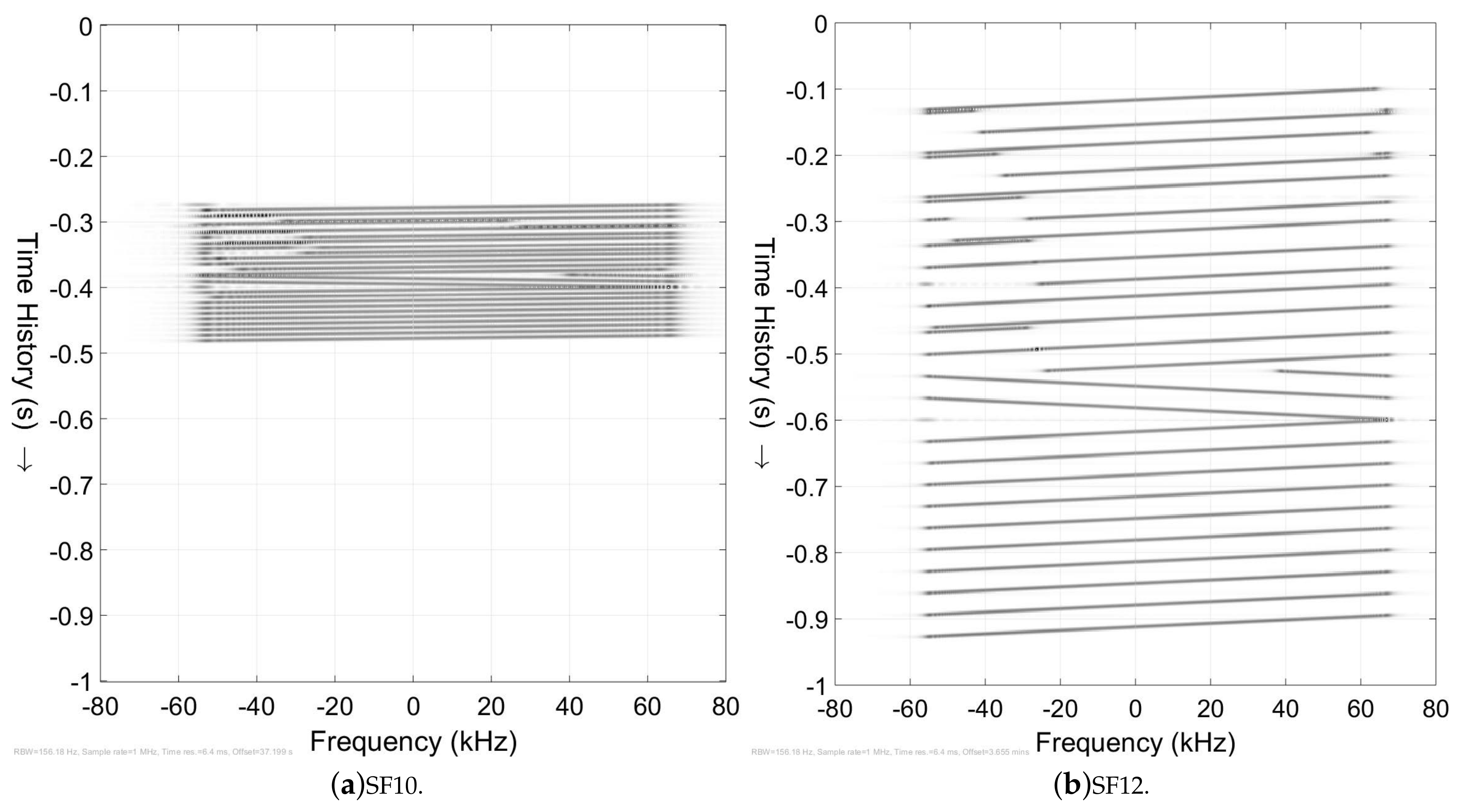
- A detailed tutorial on chirp spread spectrum (CSS) and LoRa modulation, accompanied by related equations and visual spectral analysis of LoRa frames.
- The concept of utilizing LPWAN technologies and specifically LoRaWAN for remote MG management has been introduced and conceptualized.
- An experimental testbed is provided to validate the implementation of LoRaWAN communication protocol in the control structure of power converters. Details of the communication and power system are explained so that other researchers can easily replicate the experiments.
- It is demonstrated that grid-feeding inverters can follow externally provided power setpoints. These power references are conveyed to the inverter control structure through the proposed LoRaWAN communication structure. The effects of different LoRa spreading factors (SFs) and transmission power levels are analyzed in detail.
- A communication structure has been proposed for the control and management of remote residential microgrids in remote areas. This system combines several communication protocols for best performance.
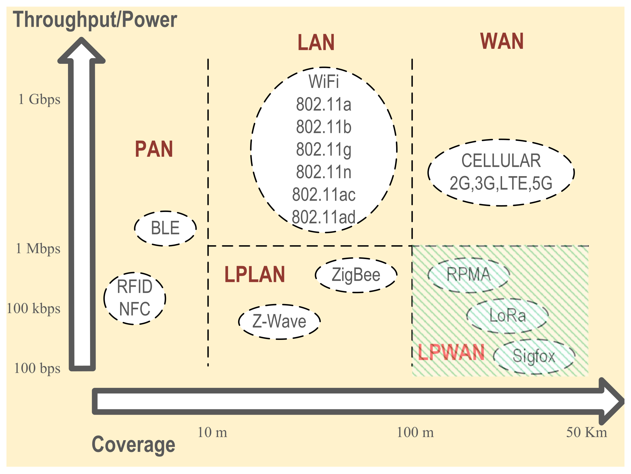
2. LPWAN Overview
- Long-range, on a scale of several kilometers or more depending on the operating environment.
- Large scale deployment that is the essence of IoT ideology.
- Operation inside unlicensed frequency bands so there are no additional costs to pay for a licensed band registration.
- Mostly used for asymmetrical communication scenarios (such as monitoring), which means the nodes can hibernate (not listening) for long intervals and just become alive and transmit when required. This contributes to the conservation of battery energy.
2.1. SigFox
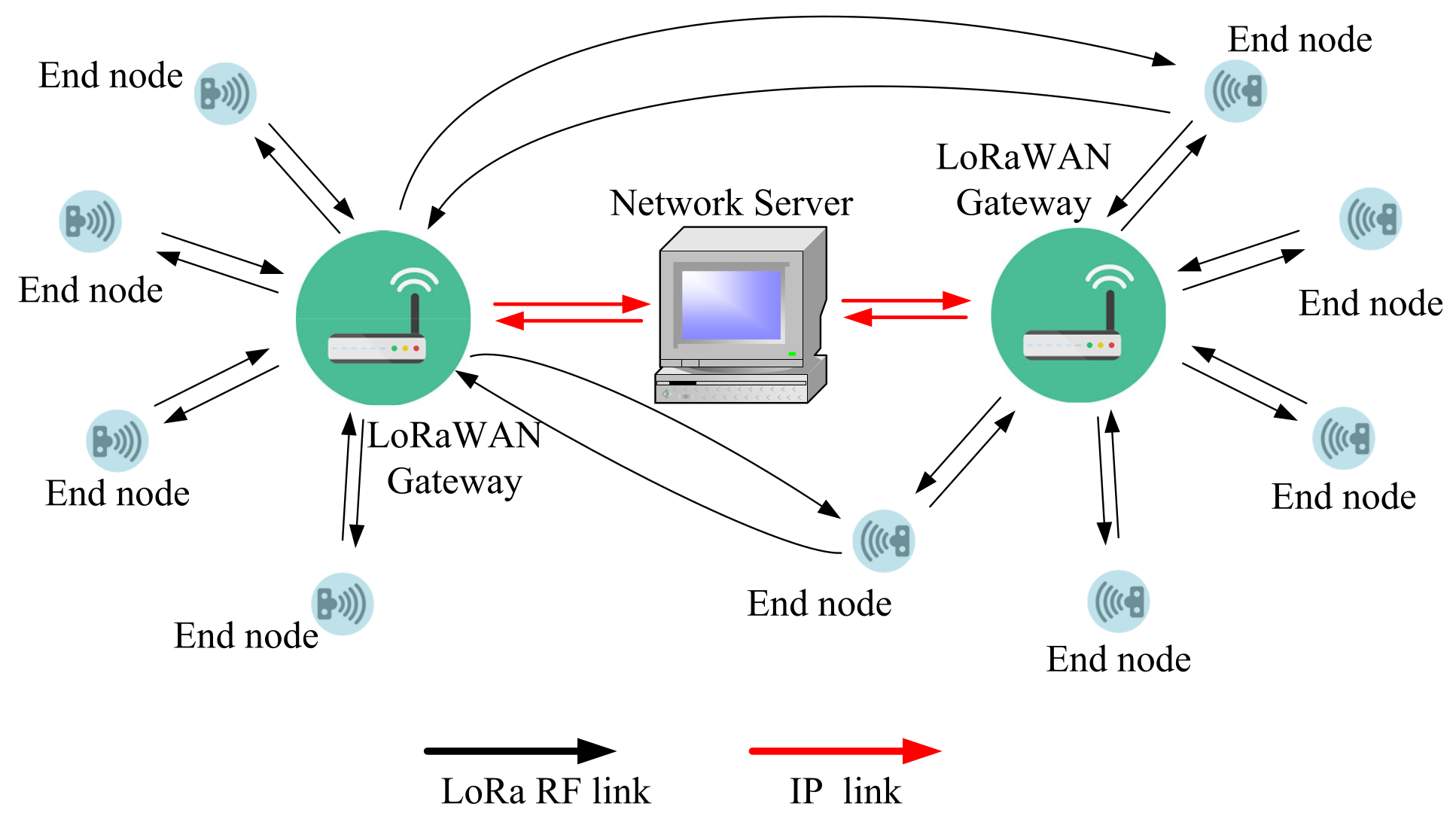
2.2. LoRaWAN
2.3. Dash7
2.4. Ingenu
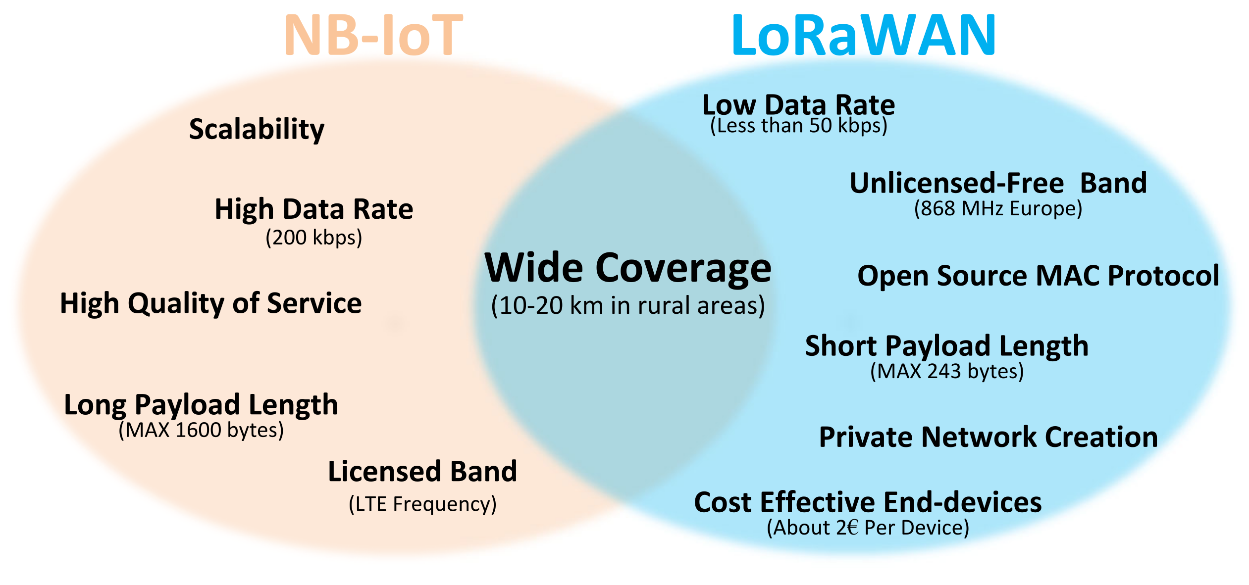
- Open-source medium access control (MAC) protocol.
- Low-cost and easy to implement end-devices.
- Non-limited daily messaging.
- The possibility of creating private networks.
3. LoRaWAN Specifications and Applications
- LoRa is a proprietary, physical layer (PHY) modulation technique and it uses chirp spread spectrum (CSS).
- LoRaWAN is an open-source protocol for medium access control (MAC).
3.1. Review of LoRaWAN and LoRa Applications in Smart Systems
- LPWANs either use ultra-narrow bands (UNB) or spread spectrum (SS) techniques which contain large latencies.
- Star topology is utilized to create ultra low power end-nodes.
- Packet loss and duplication may frequently occur due to the use of very simple MAC protocols.
- Real-time data transfer may not be possible due to the random access nature of LPWANs MAC protocols.
3.2. Spread Spectrum Technologies
3.3. LoRa Modulation
3.4. LoRaWAN MAC Protocol
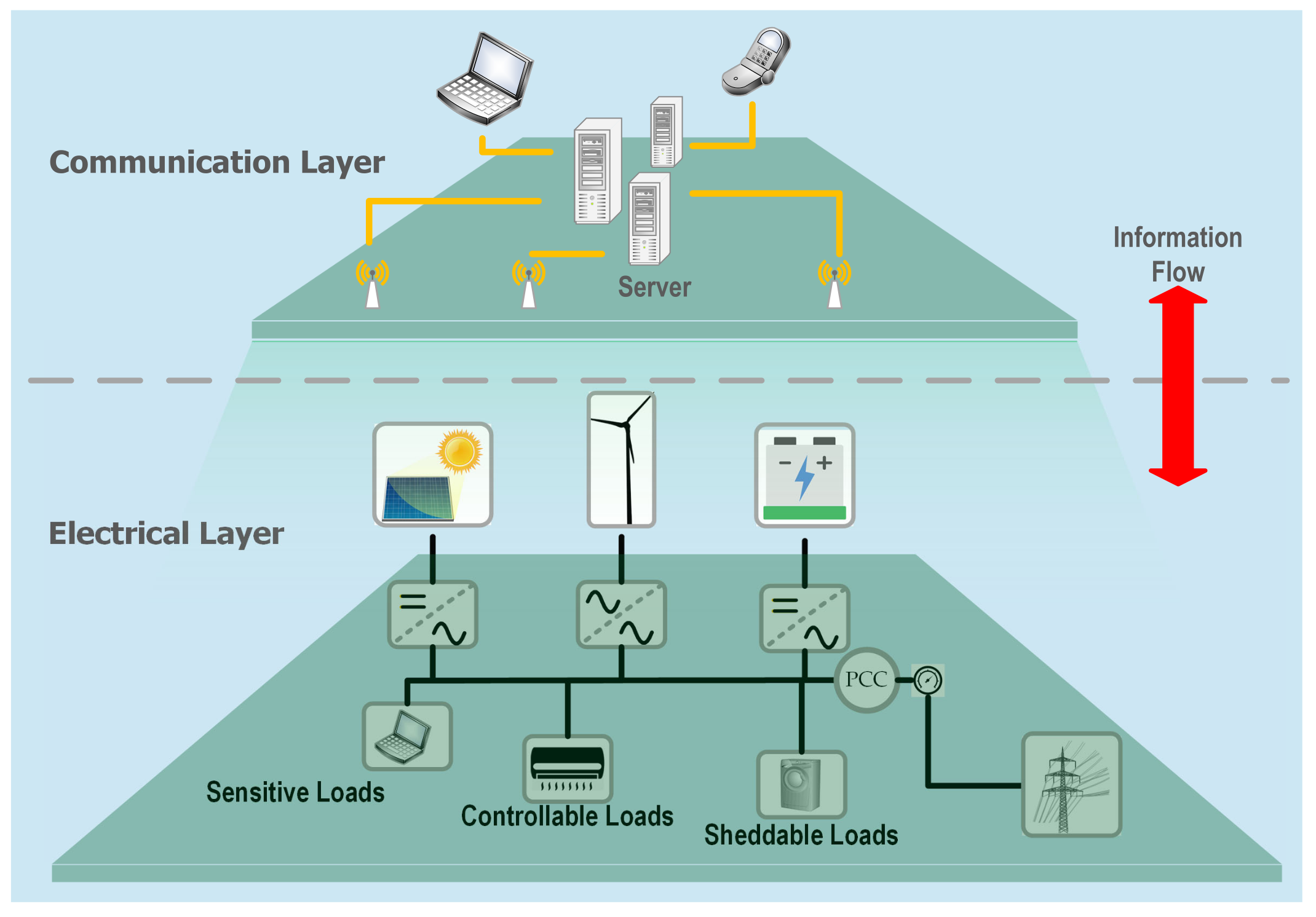
4. LPWAN Systems and MG Control
4.1. MG Communication System Design Considerations
- The physical scale of the MG: By this, we are referring to how widespread the DGs are in the system. For example, a short-range communication system may be applicable for a residential MG (smart house) architecture, whereas it might not be suitable for a small solar generation plant.
- The location of the MG: As discussed before, the lack of access to popular cellular networks is a deciding factor in considering the utilization of LPWANs.
- The level of sensitivity to latency and reliability: In LPWANs, in order to achieve low-power and long-range characteristics, throughput and robustness are being sacrificed. This should be considered when the application requires a very reliable and high throughput communication.
4.2. Residential MGs Communication Considerations
4.3. Widespread DGs, LPWANs or Cellular Networks?
5. LoRa Enabled Smart Inverters
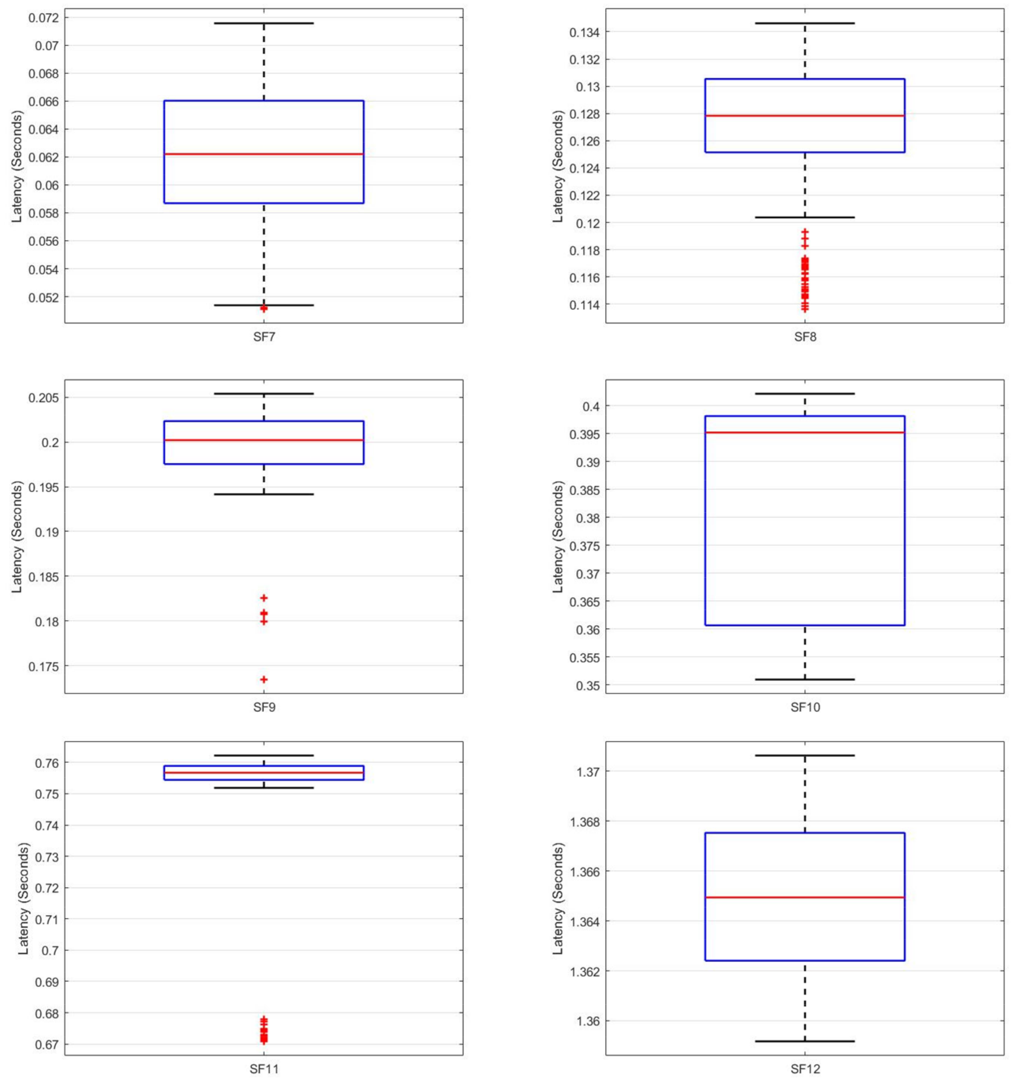
5.1. LoRa Latency Test
- The devices’ real-time clocks (RTC) are synchronized by obtaining the time from the same network time protocol (NTP) server. (Denmark—dk.pool.ntp.org, accessed on 3 September 2021).
- A timestamp is created on the transmitter just before the transmission is initiated. Therefore, the ToA, which is basically the transmission time, is included in the latency computation. This timestamp is sent as the actual payload of the Tx frames.
- The receiver is coded in a way that another timestamp is created immediately after the transmitted frame is received. In this way, on the receiver side, both transmission and reception timestamps are available and have been stored for post-processing.
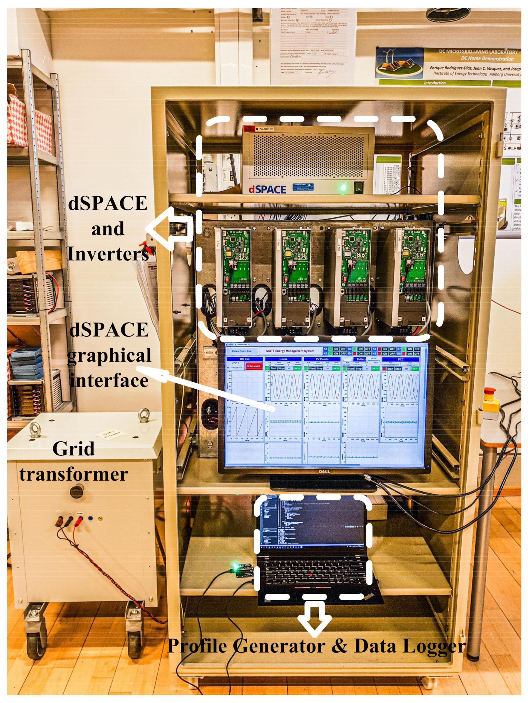
5.2. Experimental Testbed
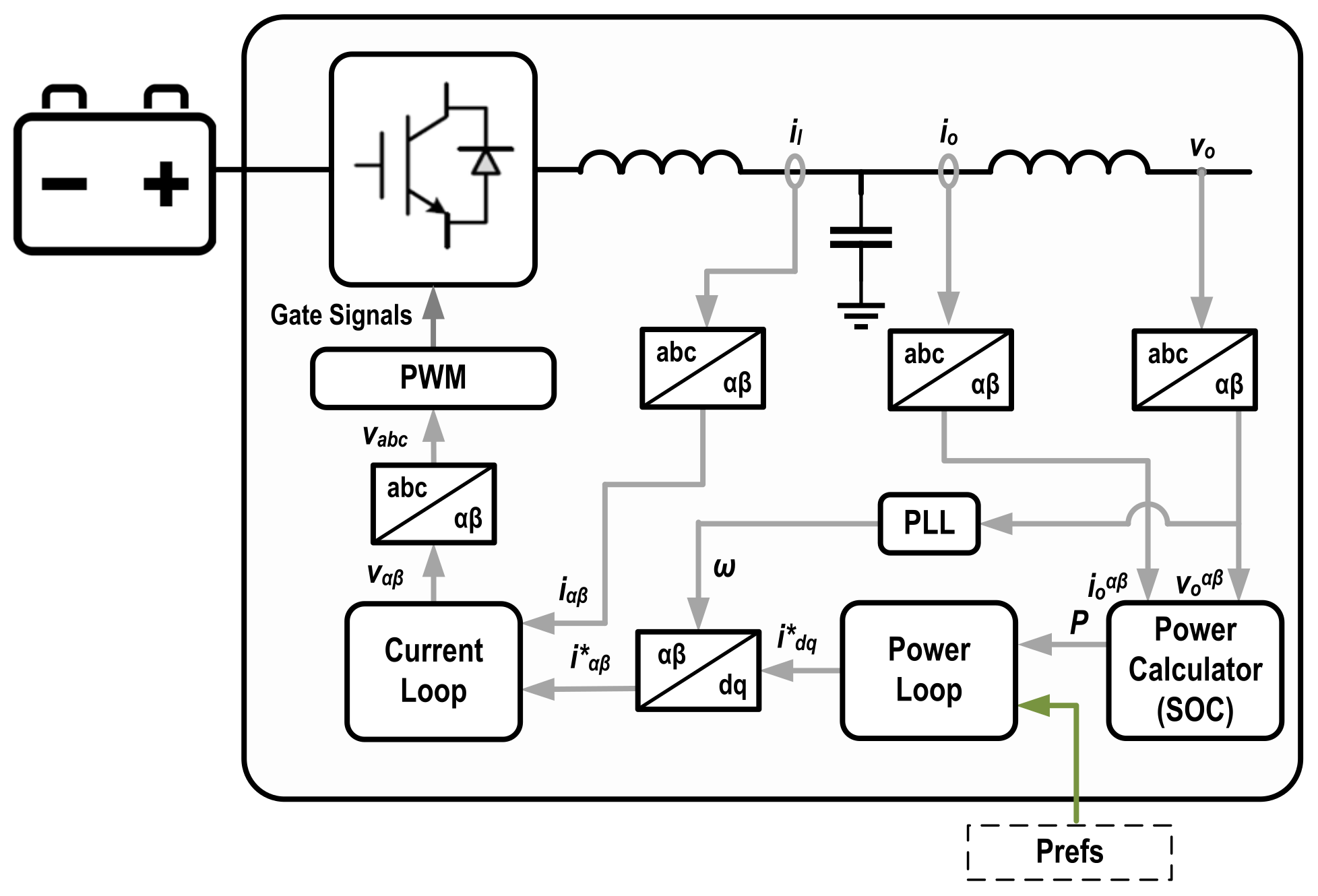
- Inverter and controller, which consisted of a Danfoss 2.2 kW bidirectional power converter and a dSPACE (DS1006) real-time control platform. A grid-feeding algorithm, prepared in Matlab/Simulink, was uploaded to the dSPACE unit to control the inverter. This class of inverters can regulate their output active and reactive power measurements by receiving external references, and an in-detail explanation of the control schema is out of the scope of this research [78]. This configuration can emulate a DG, load, or an ESS.
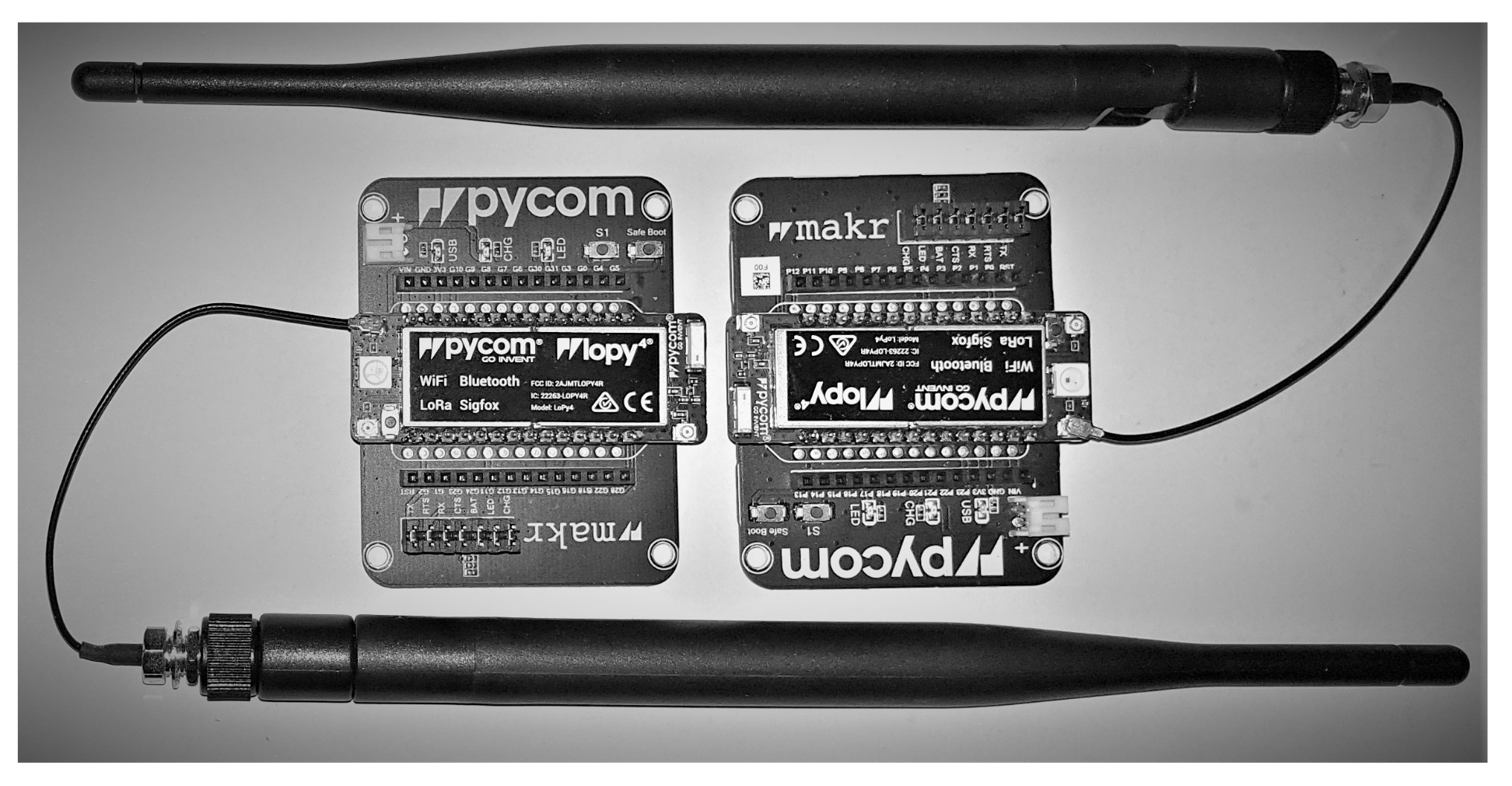
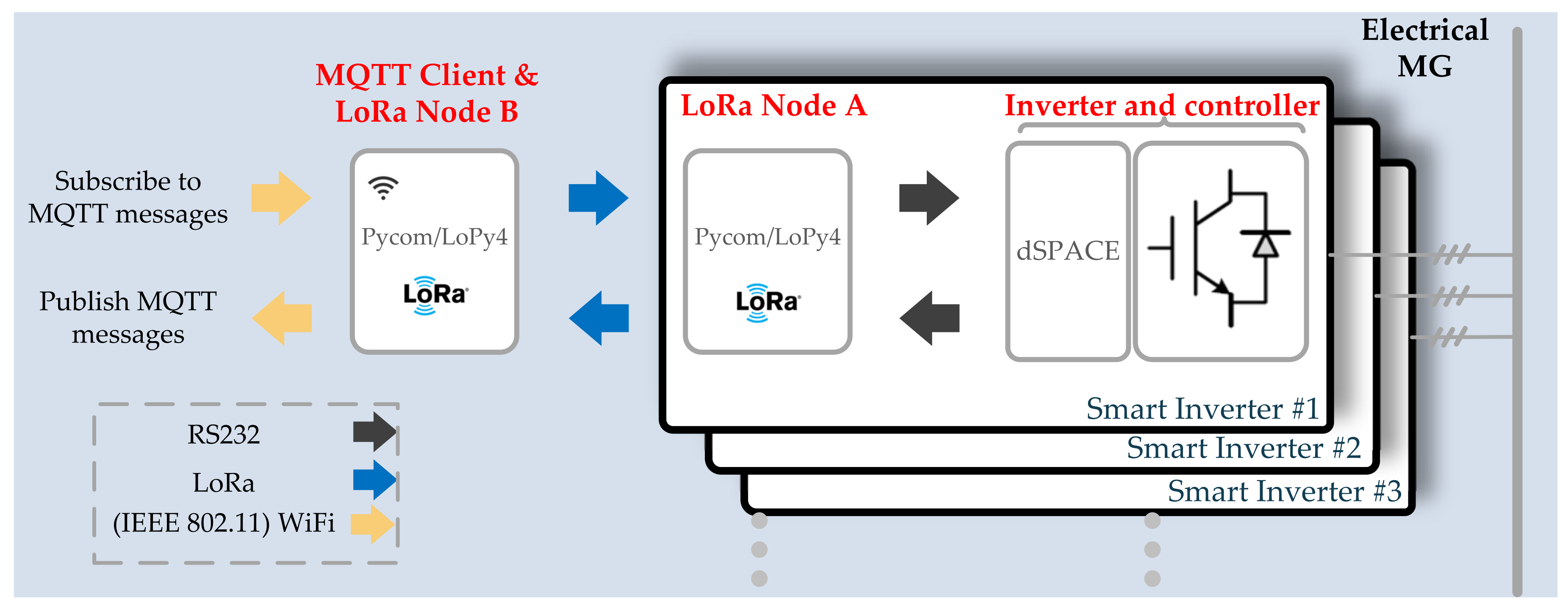
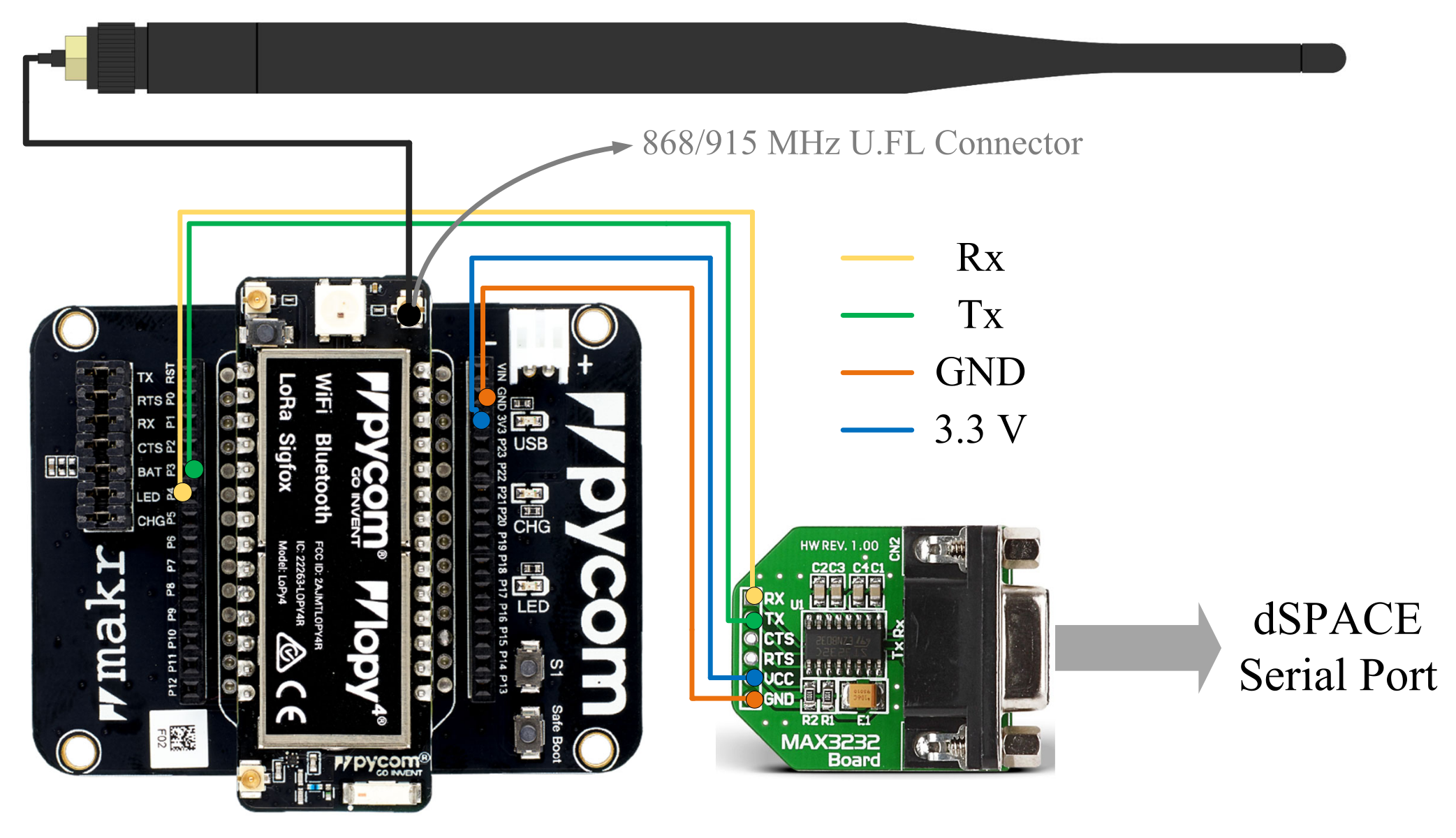
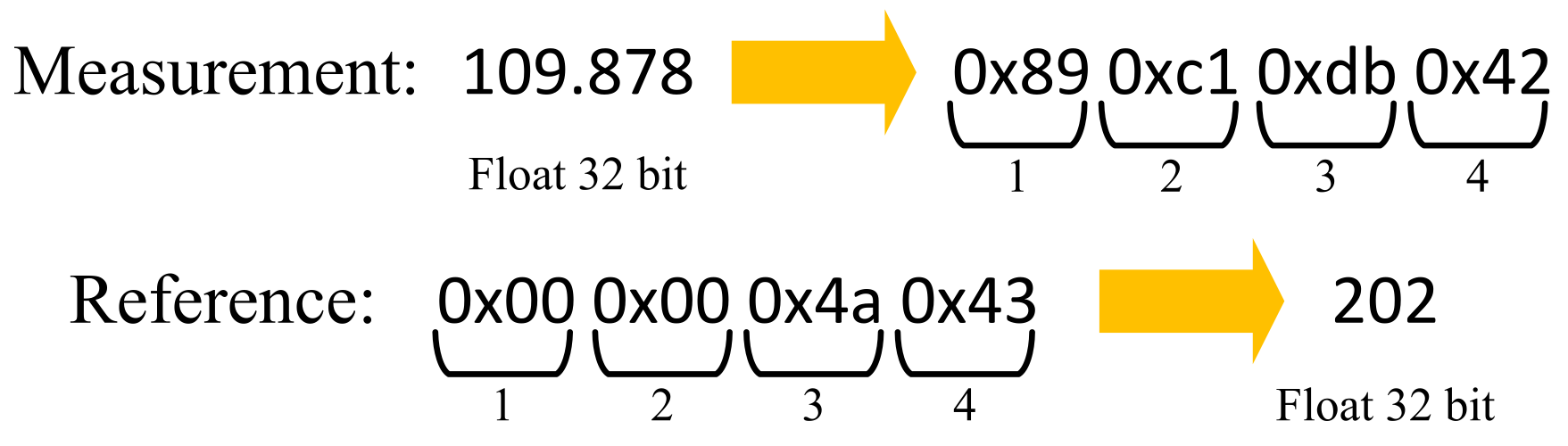
- LoRa Node A. This node that was created by coding a Pycom/Lopy4 micropython enabled microcontroller was connected to the dSPACE unit by serial communication. This was achieved by using a MAX3232 adapter to convert the microcontroller UART logical signals to RS232 protocol levels. The details of this integration are illustrated in Figure 12. The duty of this device was to receive power references, remotely generated, by LoRa and transmit them to the inverter. Besides, it was responsible for transmitting the inverters power measurements by LoRa to the other receiving end.In order to establish meaningful interconnection between this microcontroller and the aforementioned dSPACE unit, data conversion is required. In this case, the inverter power measurements were converted from their 32-bit float representations to an array of four Hex bytes to be able to be transmitted through the serial channel. These converted bytes are arranged and transmitted using the little-endian ordering. Needless to say, opposite conversions are required when references are relayed from the microcontroller to the dSPACE unit and subsequently the inverter control structure. Examples of the explained data conversion scheme are presented in Figure 13.Based on the explanations provided above, the microcontroller is acting as both a LoRa transceiver and a UART device. The configurations are listed in Table 3. It should be noted that, since several tests are conducted for different SFs and transmission powers, their values are not included in Table 3.
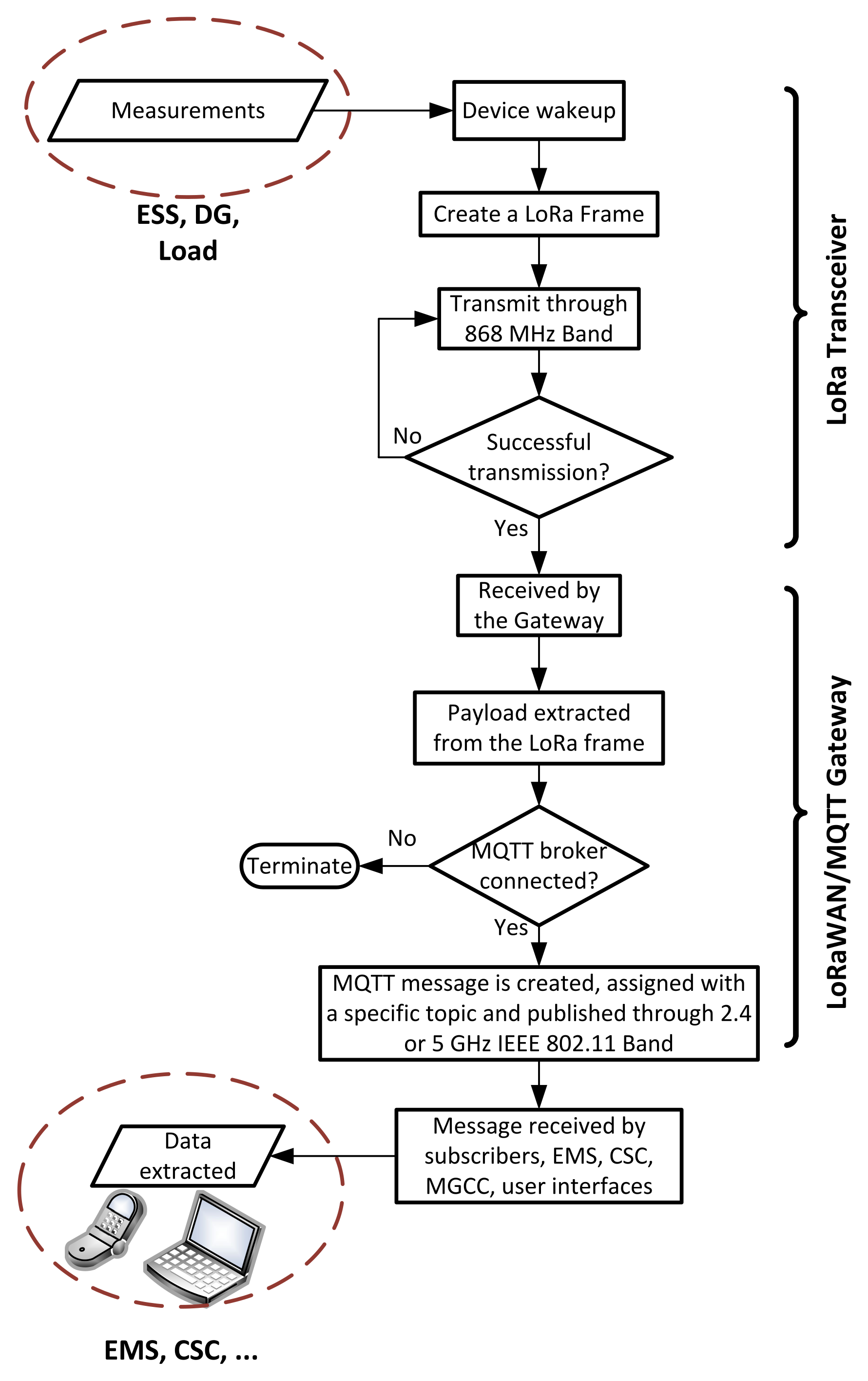
- LoRa Node B. This node was also created on a Pycom/Lopy device. It was coded to receive power references from a Matlab based profile generator by message queuing telemetry transport (MQTT) protocol, extract the payload, perform data conversion as illustrated in Figure 13, create LoRa frames, and transmit them to node A by LoRa. Node B is also responsible to receive power measurements from Node A by LoRa, convert four-byte representation to float, extract the payload, create MQTT messages, and publish over certain topics. These MQTT messages can be intercepted by other devices such as human-machine interfaces (HMIs) that are subscribing to the same MQTT topics. As a result, Node B, rather than just being a LoRa node, like Node A, was also an MQTT client therefore was WiFi-enabled. Based on this description, Node B can be regarded as a LoRaWAN/MQTT gateway that can be in connection with several Node A-class devices.


| UART Baud Rate | UART Character | LoRa Frequency | LoRa Bandwidth |
|---|---|---|---|
| 115,200 (bauds) | 8 (bits) | 868 (MHz) | 125 (kHz) |

5.3. Experimental Results
6. LoRaWAN/MQTT for Residential MG in Rural Areas: A Futuristic Case Study
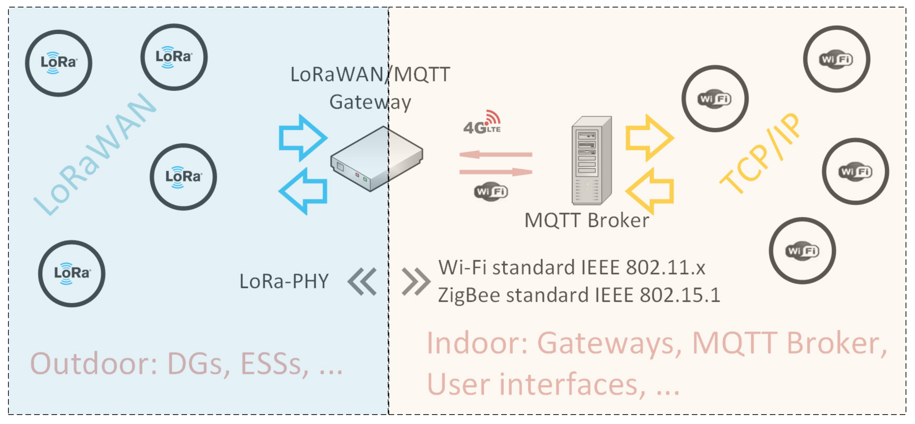
- Outdoor nodes: DGs, ESSs, electrical car charging stations, and field sensors are examples, among many more for the first class of devices. In general, all the end-nodes that are outdoors and are separated by distances more than tens of meters fit into this category.
- Indoor nodes: LoRaWAN Gateways and application servers, EMS, MG supervisory control system, user interfaces, and other indoor applications.
- TTN, like other available LoRaWAN network servers [83], are cloud-based. In other words, although the TTN is adequately secure, an internet connection is still required which may not be always favorable. This is due to possible weak network coverage, especially in remote areas that are the focus of this case study [84].
- It is more secure to maintain the local data locally. In other words, in this proposed architecture all the messages are local and bound to the limits of the MG. Therefore, if it is possible to avoid any unnecessary data interactions with cloud-based platforms, the overall security can be further improved. This means designing and utilizing local LoRaWAN servers.
7. Conclusions
- The problem has been investigated from both communication and control systems angles. This study can be useful for audiences from both aforementioned backgrounds. In the humble opinion of the authors, it may be challenging to find a similarly structured work, and normally either one of the aspects is overlooked to some extent and the focus is either on control or communication.
- Details on architecture and system design parameters for both viewpoints were described. The point-to-point LoRa communication architecture was developed by using off-the-shelf micropython enabled microprocessors, and the details are provided for other researchers that aim to replicate the system. We found out that the LoRa communication system design is logical and straightforward with ease of implementation, free spectrum, and cost-effectiveness of end-devices. On the other hand, the dSPACE hosted grid-feeding inverter control structure was also comprehensively explained. The designed control structure was performed in a stable a reliable manner, power references are followed, and no frequency synchronization problems were detected.
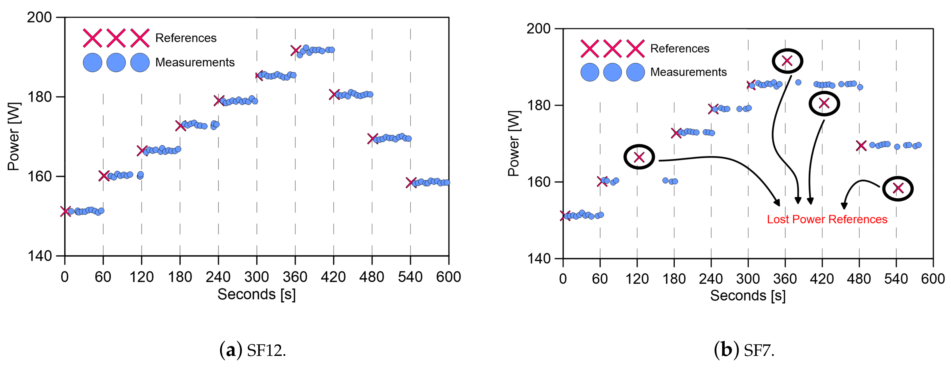
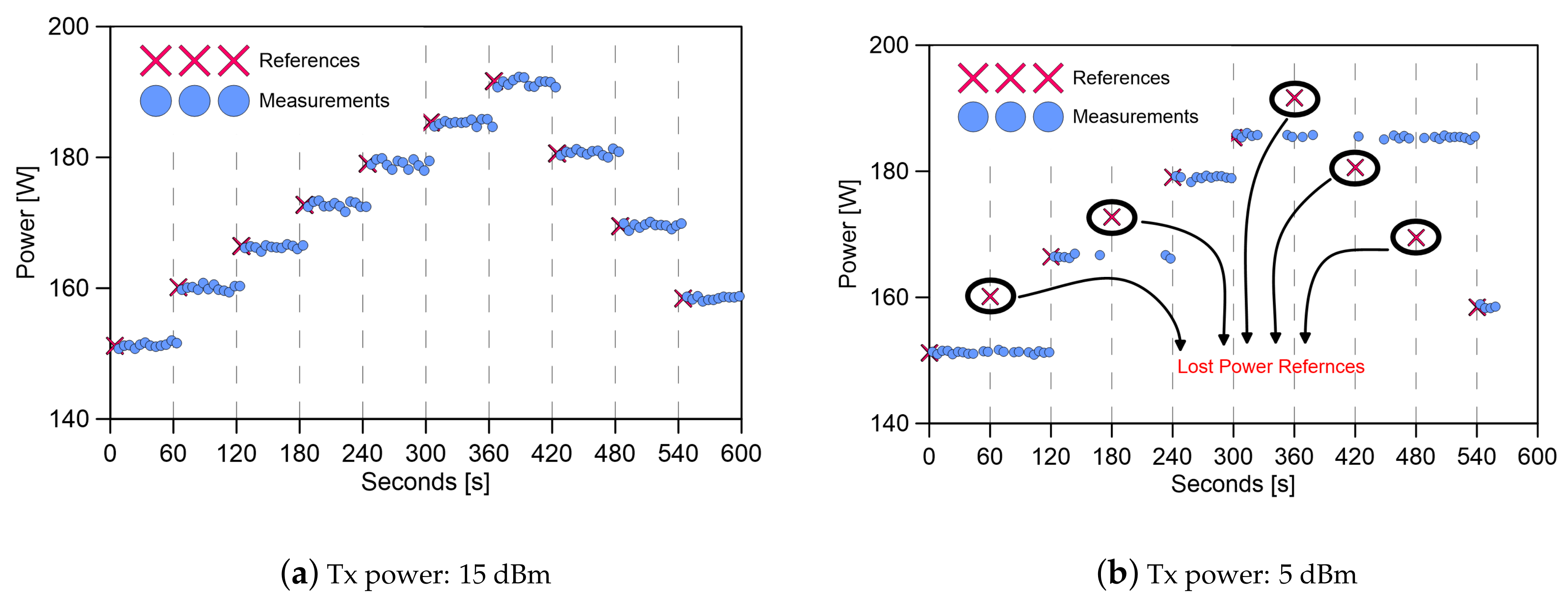
- The interaction between both systems, communication and control, was described and experimentally validated. We demonstrated the power reference following capability of the grid-feeding smart inverter by utilizing LoRa to connect the transmitter and receiver nodes. It was proved that all the SFs are not capable of creating stable and reliable communication systems, even when the range is low. It is the same for the different transmission power levels that affect the link reliability considerably. In other words, the communication system should be optimally designed so that important aspects, such as coverage, throughput, and energy consumption characteristics, match the required application.
Author Contributions
Funding
Institutional Review Board Statement
Informed Consent Statement
Conflicts of Interest
References
- Lasseter, R.; Piagi, P. Microgrid: A Conceptual Solution. In Proceedings of the 2004 IEEE 35th Annual Power Electronics Specialists Conference (IEEE Cat. No.04CH37551), Aachen, Germany, 20–25 June 2004; Volume 6, pp. 4285–4290. [Google Scholar] [CrossRef]
- Arbab-Zavar, B.; Palacios-Garcia, E.; Vasquez, J.; Guerrero, J. Smart Inverters for Microgrid Applications: A Review. Energies 2019, 12, 840. [Google Scholar] [CrossRef] [Green Version]
- Al-Fuqaha, A.; Guizani, M.; Mohammadi, M.; Aledhari, M.; Ayyash, M. Internet of Things: A Survey on Enabling Technologies, Protocols, and Applications. IEEE Commun. Surv. Tutor. 2015, 17, 2347–2376. [Google Scholar] [CrossRef]
- Ancillotti, E.; Bruno, R.; Conti, M. The role of communication systems in smart grids: Architectures, technical solutions and research challenges. Comput. Commun. 2013, 36, 1665–1697. [Google Scholar] [CrossRef] [Green Version]
- Ayoub, W.; Samhat, A.E.; Nouvel, F.; Mroue, M.; Prévotet, J.C. Internet of Mobile Things: Overview of LoRaWAN, DASH7, and NB-IoT in LPWANs Standards and Supported Mobility. IEEE Commun. Surv. Tutor. 2019, 21, 1561–1581. [Google Scholar] [CrossRef] [Green Version]
- Olatinwo, D.D.; Abu-Mahfouz, A.; Hancke, G. A survey on LPWAN technologies in WBAN for remote health-care monitoring. Sensors 2019, 19, 5268. [Google Scholar] [CrossRef] [PubMed] [Green Version]
- Augustin, A.; Yi, J.; Clausen, T.; Townsley, W.M. A study of Lora: Long range & low power networks for the internet of things. Sensors 2016, 16, 1466. [Google Scholar] [CrossRef]
- Haxhibeqiri, J.; De Poorter, E.; Moerman, I.; Hoebeke, J. A survey of LoRaWAN for IoT: From technology to application. Sensors 2018, 18, 3995. [Google Scholar] [CrossRef] [Green Version]
- Palattella, M.R.; Dohler, M.; Grieco, A.; Member, S.; Rizzo, G.; Torsner, J.; Engel, T.; Ladid, L. Internet of Things in the 5G Era: Enablers, Architecture, and Business Models. IEEE J. Sel. Areas Commun. 2016, 34, 510–527. [Google Scholar] [CrossRef] [Green Version]
- Čolaković, A.; Hadžialić, M. Internet of Things (IoT): A review of enabling technologies, challenges, and open research issues. Comput. Netw. 2018, 144, 17–39. [Google Scholar] [CrossRef]
- Cattani, M.; Boano, C.A.; Römer, K. An experimental evaluation of the reliability of lora long-range low-power wireless communication. J. Sens. Actuator Netw. 2017, 6, 7. [Google Scholar] [CrossRef] [Green Version]
- Shuda, J.E.; Rix, A.J.; Booysen, M.J. Towards Module-Level Performance and Health Monitoring of Solar PV Plants Using LoRa Wireless Sensor Networks. In Proceedings of the 2018 IEEE PES/IAS PowerAfrica, Cape Town, South Africa, 28–29 June 2018; pp. 172–177. [Google Scholar] [CrossRef]
- Centenaro, M.; Vangelista, L.; Zanella, A.; Zorzi, M. Long-range communications in unlicensed bands: The rising stars in the IoT and smart city scenarios. IEEE Wirel. Commun. 2016, 23, 60–67. [Google Scholar] [CrossRef] [Green Version]
- Kim, S.; Lee, H.; Jeon, S. An adaptive spreading factor selection scheme for a single channel lora modem. Sensors 2020, 20, 1008. [Google Scholar] [CrossRef] [Green Version]
- Gomez, C.; Veras, J.C.; Vidal, R.; Casals, L.; Paradells, J. A sigfox energy consumption model. Sensors 2019, 19, 681. [Google Scholar] [CrossRef] [Green Version]
- Raza, U.; Kulkarni, P.; Sooriyabandara, M. Low Power Wide Area Networks: An Overview. IEEE Commun. Surv. Tutor. 2017, 19, 855–873. [Google Scholar] [CrossRef] [Green Version]
- Lavric, A.; Petrariu, A.I.; Popa, V. Long Range SigFox Communication Protocol Scalability Analysis under Large-Scale, High-Density Conditions. IEEE Access 2019, 7, 35816–35825. [Google Scholar] [CrossRef]
- Chung, Y.; Ahn, J.Y.; Du Huh, J. Experiments of A LPWAN Tracking(TR) Platform Based on Sigfox Test Network. In Proceedings of the 2018 International Conference on Information and Communication Technology Convergence (ICTC), Jeju, Korea, 17–19 October 2018; pp. 1373–1376. [Google Scholar] [CrossRef]
- Jovalekic, N.; Drndarevic, V.; Pietrosemoli, E.; Darby, I.; Zennaro, M. Experimental study of LoRa transmission over seawater. Sensors 2018, 18, 2853. [Google Scholar] [CrossRef] [Green Version]
- Cetinkaya, O.; Akan, O.B. A DASH7-based power metering system. In Proceedings of the 2015 12th Annual IEEE Consumer Communications and Networking Conference (CCNC), Las Vegas, NV, USA, 9–12 January 2015; pp. 406–411. [Google Scholar] [CrossRef] [Green Version]
- Weyn, M.; Ergeerts, G.; Berkvens, R.; Wojciechowski, B.; Tabakov, Y. DASH7 alliance protocol 1.0: Low-power, mid-range sensor and actuator communication. In Proceedings of the 2015 IEEE Conference on Standards for Communications and Networking (CSCN), Tokyo, Japan, 28–30 October 2015; pp. 54–59. [Google Scholar] [CrossRef]
- Lee, H.; Chung, S.H.; Lee, Y.S.; Ha, Y. Performance comparison of DASH7 and ISO/IEC 18000-7 for fast tag collection with an enhanced CSMA/CA protocol. In Proceedings of the 2013 IEEE 10th International Conference on High Performance Computing and Communications and 2013 IEEE International Conference on Embedded and Ubiquitous Computing, Zhangjiajie, China, 13–15 November 2013; pp. 769–776. [Google Scholar] [CrossRef]
- Qadir, Q.M.; Rashid, T.A.; Al-Salihi, N.K.; Ismael, B.; Kist, A.A.; Zhang, Z. Low power wide area networks: A survey of enabling technologies, applications and interoperability needs. IEEE Access 2018, 6, 77454–77473. [Google Scholar] [CrossRef]
- Peña Queralta, J.; Gia, T.N.; Zou, Z.; Tenhunen, H.; Westerlund, T. Comparative study of LPWAN technologies on unlicensed bands for M2M communication in the IoT: Beyond Lora and Lorawan. Procedia Comput. Sci. 2019, 155, 343–350. [Google Scholar] [CrossRef]
- Haxhibeqiri, J.; Van den Abeele, F.; Moerman, I.; Hoebeke, J. LoRa scalability: A simulation model based on interference measurements. Sensors 2017, 17, 1193. [Google Scholar] [CrossRef] [Green Version]
- Bouguera, T.; Diouris, J.F.; Chaillout, J.J.; Jaouadi, R.; Andrieux, G. Energy consumption model for sensor nodes based on LoRa and LoRaWAN. Sensors 2018, 18, 2104. [Google Scholar] [CrossRef] [Green Version]
- Petäjäjärvi, J.; Mikhaylov, K.; Hämäläinen, M.; Iinatti, J. Evaluation of LoRa LPWAN Technology for Remote Health and Wellbeing Monitoring. In Proceedings of the 2016 10th International Symposium on Medical Information and Communication Technology (ISMICT), Targoviste, Romania, 29 June–1 July 2017; pp. 1–5. [Google Scholar] [CrossRef]
- Cihan Ta, N.; Sastry, C.; Song, Z. IEEE 802.15.4 Throughput Analysis under IEEE 802.11 Interference. In Proceedings of the International Symposium on Innovations and Real Time Applications of Distributed Sensor Networks, Shreveport, 26–27 November 2007. [Google Scholar]
- Li, L.; Ren, J.; Zhu, Q. On the application of LoRa LPWAN technology in Sailing Monitoring System. In Proceedings of the 2017 13th Annual Conference on Wireless On-demand Network Systems and Services (WONS), Jackson, WY, USA, 21–24 February 2017; pp. 77–80. [Google Scholar] [CrossRef]
- Mdhaffar, A.; Chaari, T.; Larbi, K.; Jmaiel, M.; Freisleben, B. IoT-based health monitoring via LoRaWAN. In Proceedings of the IEEE EUROCON 2017 -17th International Conference on Smart Technologies, Ohrid, Macedonia, 6–8 July 2017; pp. 519–524. [Google Scholar] [CrossRef]
- Catherwood, P.A.; Steele, D.; Little, M.; McComb, S.; McLaughlin, J. A Community-Based IoT Personalized Wireless Healthcare Solution Trial. IEEE J. Transl. Eng. Health Med. 2018, 6. [Google Scholar] [CrossRef]
- Pasolini, G.; Buratti, C.; Feltrin, L.; Zabini, F.; de Castro, C.; Verdone, R.; Andrisano, O. Smart city pilot projects using LoRa and IEEE802.15.4 technologies. Sensors 2018, 18, 1118. [Google Scholar] [CrossRef] [Green Version]
- Jeon, Y.; Ju, H.I.; Yoon, S. Design of an LPWAN communication module based on secure element for smart parking application. In Proceedings of the 2018 IEEE International Conference on Consumer Electronics (ICCE), Las Vegas, NV, USA, 12–14 January 2018; pp. 1–2. [Google Scholar] [CrossRef]
- Jawad, H.M.; Nordin, R.; Gharghan, S.K.; Jawad, A.M.; Ismail, M. Energy-efficient wireless sensor networks for precision agriculture: A review. Sensors 2017, 17, 1781. [Google Scholar] [CrossRef] [Green Version]
- Sartori, D.; Brunelli, D. A smart sensor for precision agriculture powered by microbial fuel cells. In Proceedings of the 2016 IEEE Sensors Applications Symposium (SAS), Catania, Italy, 20–22 April 2016; pp. 1–6. [Google Scholar] [CrossRef]
- Pasetti, M.; Rinaldi, S.; Sisinni, E.; Ferrari, P.; Flammini, A.; Ragaini, E.; Longo, M.; Zaninelli, D. On the Use of Synchronized LoRaWAN for the Coordination of Distributed Energy Resources in Smart Grids. In Proceedings of the 2019 AEIT International Annual Conference (AEIT), Florence, Italy, 18–20 September 2019; Volume 379327, pp. 1–6. [Google Scholar] [CrossRef]
- Pasetti, M.; Sisinni, E.; Ferrari, P.; Rinaldi, S.; Depari, A.; Bellagente, P.; Giustina, D.D.; Flammini, A. Evaluation of the use of class B LoraWAn for the coordination of distributed interface protection systems in smart grids. J. Sens. Actuator Netw. 2020, 9, 13. [Google Scholar] [CrossRef] [Green Version]
- Mikhaylov, K.; Moiz, A.; Pouttu, A.; Martín Rapún, J.M.; Gascon, S.A. LoRa WAN for Wind Turbine Monitoring: Prototype and Practical Deployment. In Proceedings of the 2018 10th International Congress on Ultra Modern Telecommunications and Control Systems and Workshops (ICUMT), Moscow, Russia, 5–9 November 2018; pp. 1–6. [Google Scholar] [CrossRef] [Green Version]
- Gallardo, J.L.; Ahmed, M.A.; Jara, N. LoRa IoT-Based Architecture for Advanced Metering Infrastructure in Residential Smart Grid. IEEE Access 2021, 9, 124295–124312. [Google Scholar] [CrossRef]
- Barriquello, C.H.; Bernardon, D.P.; Canha, L.N.; e Silva, F.E.; Porto, D.S.; da Silveira Ramos, M.J. Performance assessment of a low power wide area network in rural smart grids. In Proceedings of the 2017 52nd International Universities Power Engineering Conference (UPEC), Heraklion, Greece, 28–31 August 2017; pp. 1–4. [Google Scholar] [CrossRef]
- Nguyen, T.T.; Nguyen, H.H.; Barton, R.; Grossetete, P. Efficient Design of Chirp Spread Spectrum Modulation for Low-Power Wide-Area Networks. IEEE Internet Things J. 2019, 6, 9503–9515. [Google Scholar] [CrossRef]
- Scholtz, R. The Spread Spectrum Concept. IEEE Trans. Commun. 1977, 25, 748–755. [Google Scholar] [CrossRef]
- Pickholtz, R.; Schilling, D.; Milstein, L. Theory of Spread-Spectrum Communications—A Tutorial. IEEE Trans. Commun. 1982, 30, 855–884. [Google Scholar] [CrossRef] [Green Version]
- Liu, F.; Marcellin, M.W.; Goodman, N.A.; Bilgin, A. Compressive Sampling for Detection of Frequency-Hopping Spread Spectrum Signals. IEEE Trans. Signal Process. 2016, 64, 5513–5524. [Google Scholar] [CrossRef]
- Knapp, A.; Pap, L. Performance analysis of pulse position based chirp spread spectrum technique for multiple access. In Proceedings of the 2017 25th International Conference on Software, Telecommunications and Computer Networks (SoftCOM), Split, Croatia, 21–23 September 2017; pp. 1–5. [Google Scholar] [CrossRef]
- Springer, A.; Gugler, W.; Huemer, M.; Reindl, L.; Ruppel, C.C.; Weigel, R. Spread spectrum communications using chirp signals. In Proceedings of the IEEE/AFCEA EUROCOMM 2000. Information Systems for Enhanced Public Safety and Security (Cat. No.00EX405), Munich, Germany, 19 May 2000; pp. 166–170. [Google Scholar] [CrossRef]
- Georgiou, O.; Raza, U. Low Power Wide Area Network Analysis: Can LoRa Scale? IEEE Wirel. Commun. Lett. 2017, 6, 162–165. [Google Scholar] [CrossRef] [Green Version]
- Knight, M.; Seeber, B.; Net, B. Decoding LoRa: Realizing a Modern LPWAN with SDR. In Proceedings of the GNU Radio Conference, Boulder, CO, USA, 6 September 2016. [Google Scholar]
- Van Den Abeele, F.; Haxhibeqiri, J.; Moerman, I.; Hoebeke, J. Scalability Analysis of Large-Scale LoRaWAN Networks in ns-3. IEEE Internet Things J. 2017, 4, 2186–2198. [Google Scholar] [CrossRef] [Green Version]
- Shen, Y.; Cosman, P.C.; Milstein, L.B. Error-resilient video communications over CDMA networks with a bandwidth constraint. IEEE Trans. Image Process. 2006, 15, 3241–3252. [Google Scholar] [CrossRef] [PubMed]
- Vangelista, L. Frequency Shift Chirp Modulation: The LoRa Modulation. IEEE Signal Process. Lett. 2017, 24, 1818–1821. [Google Scholar] [CrossRef]
- Reynders, B.; Wang, Q.; Tuset-Peiro, P.; Vilajosana, X.; Pollin, S. Improving reliability and scalability of LoRaWANs through lightweight scheduling. IEEE Internet Things J. 2018, 5, 1830–1842. [Google Scholar] [CrossRef]
- Marnay, C.; Chatzivasileiadis, S.; Abbey, C.; Iravani, R.; Joos, G.; Lombardi, P.; Mancarella, P.; Von Appen, J. Microgrid evolution roadmap. In Proceedings of the 2015 International Symposium on Smart Electric Distribution Systems and Technologies (EDST), Vienna, Austria, 8–11 September 2015; pp. 139–144. [Google Scholar] [CrossRef]
- Guerrero, J.M.; Vasquez, J.C.; Matas, J.; De Vicuña, L.G.; Castilla, M. Hierarchical control of droop-controlled AC and DC microgrids—A general approach toward standardization. IEEE Trans. Ind. Electron. 2011, 58, 158–172. [Google Scholar] [CrossRef]
- Guerrero, J.M.; Berbel, N.; Matas, J.; Sosa, J.L.; De Vicuña, L.G. Control of line-interactive UPS connected in parallel forming a microgrid. In Proceedings of the 2007 IEEE International Symposium on Industrial Electronics, Vigo, Spain, 4–7 June 2007; pp. 2667–2672. [Google Scholar] [CrossRef]
- Bidram, A.; Davoudi, A. Hierarchical structure of microgrids control system. IEEE Trans. Smart Grid 2012, 3, 1963–1976. [Google Scholar] [CrossRef]
- Vandoorn, T.L.; Vasquez, J.C.; De Kooning, J.; Guerrero, J.M.; Vandevelde, L. Microgrids: Hierarchical control and an overview of the control and reserve management strategies. IEEE Ind. Electron. Mag. 2013, 7, 42–55. [Google Scholar] [CrossRef] [Green Version]
- Simpson-Porco, J.W.; Shafiee, Q.; Dorfler, F.; Vasquez, J.C.; Guerrero, J.M.; Bullo, F. Secondary Frequency and Voltage Control of Islanded Microgrids via Distributed Averaging. IEEE Trans. Ind. Electron. 2015, 62, 7025–7038. [Google Scholar] [CrossRef]
- Wu, D.; Dragicevic, T.; Vasquez, J.C.; Guerrero, J.M.; Guan, Y. Secondary coordinated control of islanded microgrids based on consensus algorithms. In Proceedings of the 2014 IEEE Energy Conversion Congress and Exposition (ECCE), Pittsburgh, PA, USA, 14–18 September 2014; pp. 4290–4297. [Google Scholar] [CrossRef] [Green Version]
- Bidram, A.; Davoudi, A.; Lewis, F.L.; Guerrero, J.M. Distributed cooperative secondary control of microgrids using feedback linearization. IEEE Trans. Power Syst. 2013, 28, 3462–3470. [Google Scholar] [CrossRef] [Green Version]
- Shafiee, Q.; Guerrero, J.M.; Vasquez, J.C. Distributed secondary control for islanded microgrids-a novel approach. IEEE Trans. Power Electron. 2014, 29, 1018–1031. [Google Scholar] [CrossRef] [Green Version]
- Arbab-zavar, B.; Palacios-garcia, E.J.; Vasquez, J.C. Message Queuing Telemetry Transport Communication Infrastructure for Grid-Connected AC Microgrids Management. Energies 2021, 14, 5610. [Google Scholar] [CrossRef]
- CEN-CENELEC-ETSI Smart Grid Coordination Group. Smart Grid Reference Architecture; CEN-CENELEC-ETSI Smart Grid Coordination Group: Brussels, Belgium, 2012; pp. 1–107. [Google Scholar]
- Santodomingo, R.; Uslar, M.; Göring, A.; Gottschalk, M.; Nordstrom, L.; Saleem, A.; Chenine, M. SGAM-based methodology to analyse Smart Grid solutions in DISCERN European research project. In Proceedings of the 2014 IEEE International Energy Conference (ENERGYCON), Cavtat, Croatia, 13–16 May 2014; pp. 751–758. [Google Scholar] [CrossRef]
- Froiz-míguez, I.; Fernández-caramés, T.M.; Fraga-lamas, P.; Castedo, L. Design, Implementation and Practical Evaluation of an IoT home automation system for fog computing applications based on MQTT and Zigbee-wifi sensor nodes. Sensors 2018, 18, 2660. [Google Scholar] [CrossRef] [Green Version]
- Zhang, Y.; Yu, R.; Xie, S.; Yao, W.; Xiao, Y.; Guizani, M. Home M2M networks: Architectures, standards, and QoS improvement. IEEE Commun. Mag. 2011, 49, 44–52. [Google Scholar] [CrossRef]
- Kuzlu, M.; Pipattanasomporn, M.; Rahman, S. Review of communication technologies for smart homes/building applications. In Proceedings of the 2015 IEEE Innovative Smart Grid Technologies - Asia (ISGT ASIA), Bangkok, Thailand, 3–6 November 2015; pp. 1–6. [Google Scholar] [CrossRef]
- Meyer, M. TCP performance over GPRS. IEEE Wirel. Commun. Netw. Conf. WCNC 1999, 3, 1248–1252. [Google Scholar]
- Mangalvedhe, N.; Ratasuk, R.; Ghosh, A. NB-IoT deployment study for low power wide area cellular IoT. In Proceedings of the 2016 IEEE 27th Annual International Symposium on Personal, Indoor, and Mobile Radio Communications (PIMRC), Valencia, Spain, 4–8 September 2016; pp. 1–6. [Google Scholar] [CrossRef]
- Lauridsen, M.; Nguyen, H.; Vejlgaard, B.; Kovacs, I.Z.; Mogensen, P.; Sorensen, M. Coverage Comparison of GPRS, NB-IoT, LoRa, and SigFox in a 7800 km Area. IEEE Veh. Technol. Conf. 2017, 2017, 9–13. [Google Scholar] [CrossRef] [Green Version]
- Vejlgaard, B.; Lauridsen, M.; Nguyen, H.; Kovacs, I.Z.; Mogensen, P.; Sorensen, M. Coverage and Capacity Analysis of Sigfox, LoRa, GPRS, and NB-IoT. IEEE Veh. Technol. Conf. 2017, 2017, 3–7. [Google Scholar] [CrossRef] [Green Version]
- Mekki, K.; Bajic, E.; Chaxel, F.; Meyer, F. A comparative study of LPWAN technologies for large-scale IoT deployment. ICT Express 2019, 5, 1–7. [Google Scholar] [CrossRef]
- Mekki, K.; Bajic, E.; Chaxel, F.; Meyer, F. Overview of Cellular LPWAN Technologies for IoT Deployment: Sigfox, LoRaWAN, and NB-IoT. In Proceedings of the 2018 IEEE International Conference on Pervasive Computing and Communications Workshops (PerCom Workshops), Athens, Greece, 19–23 March 2018; pp. 197–202. [Google Scholar] [CrossRef]
- Jubin Sebastian, E.; Sikora, A.; Schappacher, M.; Amjad, Z. Test and measurement of LPWAN and cellular IoT networks in a unified testbed. In Proceedings of the 2019 IEEE 17th International Conference on Industrial Informatics (INDIN), Helsinki, Finland, 22–25 July 2019; pp. 1521–1527. [Google Scholar] [CrossRef]
- Singh, D.; Augustin, S.; Kretschmer, M. LoRaWAN Evaluation for IoT Communications. In Proceedings of the 2018 International Conference on Advances in Computing, Communications and Informatics (ICACCI), Bangalore, India, 19–22 September 2018; pp. 163–171. [Google Scholar] [CrossRef]
- Noreen, U.; Ahcenebounceuruniv-brestfr, E.; Clavier, L. A Study of LoRa Low Power and Wide Area Network Technology. In Proceedings of the 2017 International Conference on Advanced Technologies for Signal and Image Processing (ATSIP), Fez, Morocco, 22–24 May 2017; pp. 1–6. [Google Scholar] [CrossRef]
- Meng, L.; Luna, A.; Díaz, E.R.; Sun, B.; Dragicevic, T.; Savaghebi, M.; Vasquez, J.C.; Guerrero, J.M.; Graells, M.; Andrade, F. Flexible System Integration and Advanced Hierarchical Control Architectures in the Microgrid Research Laboratory of Aalborg University. IEEE Trans. Ind. Appl. 2016, 52, 1736–1749. [Google Scholar] [CrossRef] [Green Version]
- Rocabert, J.; Luna, A.; Blaabjerg, F.; Rodríguez, P. Control of power converters in AC microgrids. IEEE Trans. Power Electron. 2012, 27, 4734–4749. [Google Scholar] [CrossRef]
- Havard, N.; McGrath, S.; Flanagan, C.; MacNamee, C. Smart building based on internet of things technology. In Proceedings of the 2018 12th International Conference on Sensing Technology (ICST), Limerick, Ireland, 4–6 December 2018; pp. 278–281. [Google Scholar] [CrossRef]
- Schmitt, C.; Meier, J.; Diez, M.; Stiller, B. OTIoT-A browser-based object tracking solution for the Internet of Things. In Proceedings of the 2018 IEEE 4th World Forum on Internet of Things (WF-IoT), Singapore, 5–8 February 2018; pp. 445–451. [Google Scholar] [CrossRef]
- Fargas, B.C.; Petersen, M.N. GPS-free geolocation using LoRa in low-power WANs. In Proceedings of the 2017 Global Internet of Things Summit (GIoTS), Geneva, Switzerland, 6–9 June 2017; pp. 1–6. [Google Scholar] [CrossRef] [Green Version]
- The Things Network. Available online: https://https://www.thethingsnetwork.org// (accessed on 1 November 2021).
- Lavric, A.; Popa, V. LoRa™ Wide-Area Networks from an Internet of Things perspective. In Proceedings of the 2017 9th International Conference on Electronics, Computers and Artificial Intelligence (ECAI), Targoviste, Romania, 29 June–1 July 2017; pp. 1–4. [Google Scholar] [CrossRef]
- Barro, P.A.; Zennaro, M.; Pietrosemoli, E. TLTN—The local things network: On the design of a LoRaWAN gateway with autonomous servers for disconnected communities. IFIP Wirel. Days 2019, 2019, 12–15. [Google Scholar] [CrossRef]


| Band | Channel Width | Modulation | Coverage | Bit Rate | |
|---|---|---|---|---|---|
| SigFox | 868 MHz(EU), 902 MHz(US)-ISM | 100 Hz(UL), 1.5 kHz(DL) | UNB-DBPSK(Ul), GFSK (Dl) | 10 km (urban) 40 km (rural) | 100 bps (UL), 600 bps (DL) |
| LoRaWAN | 868 MHz(EU), 915 MHz(US)-ISM | 125, 250 or 500 kHz | LoRa-CSS | 1–2 km (urban) 15 km (rural) | MAX 50 kbps |
| Dash7 | 433/868/915 MHz-ISM | 25 or 200 kHz | (2)GFSK | 1–2 km | MAX 150 kbps |
| Ingenu | 2.4 GHz -ISM | 1 MHz | RPMA-DSSS | 15 km (urban) | 624 kbps (UL), 156 kbps (DL) |
| SF7 | SF8 | SF9 | SF10 | SF11 | SF12 | |
|---|---|---|---|---|---|---|
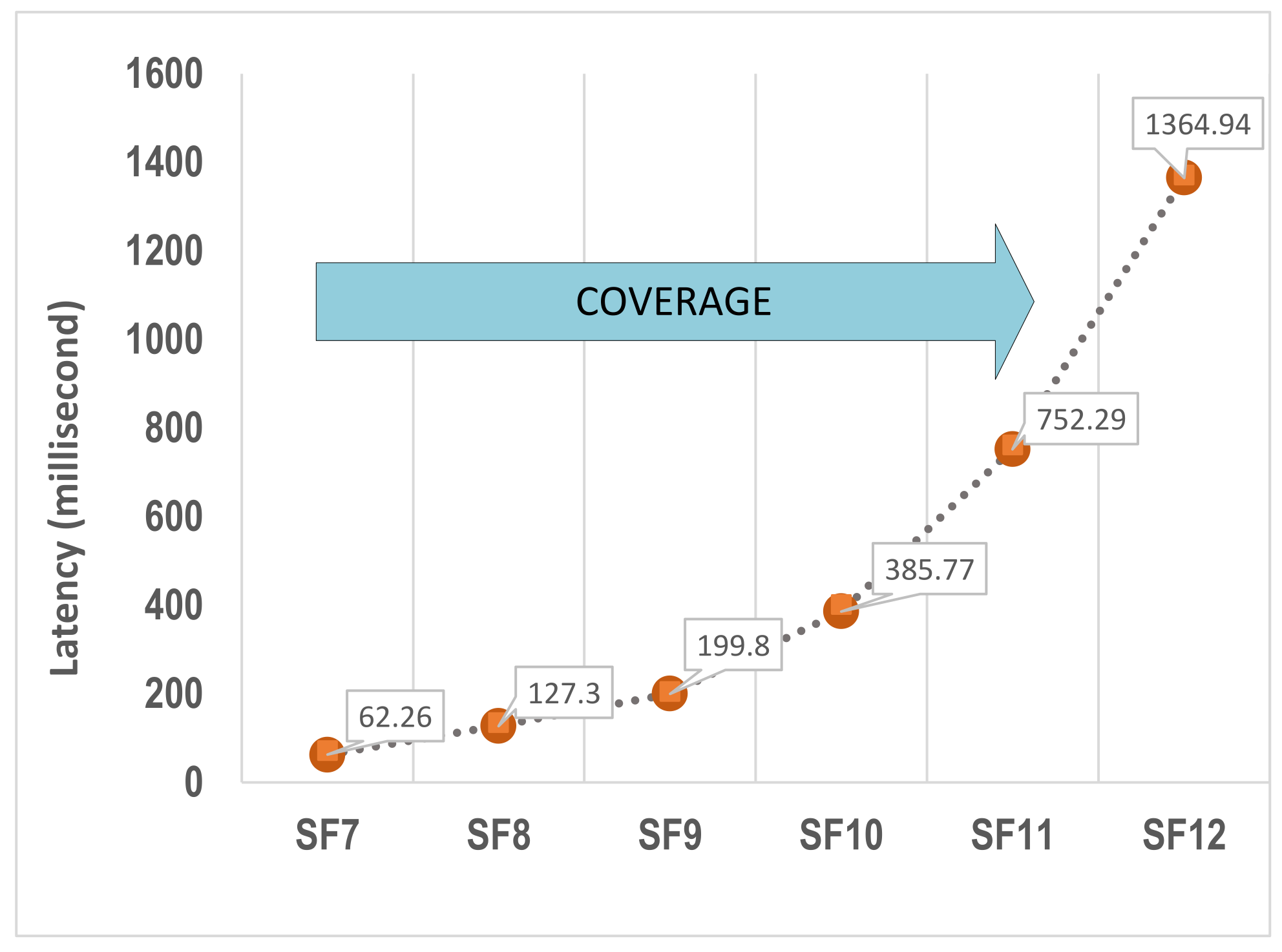
| Theoretical ToA | 0.046 | 0.086 | 0.162 | 0.304 | 0.583 | 1.102 |
| AVE Measured Latency | 0.062 | 0.127 | 0.200 | 0.386 | 0.752 | 1.365 |
Publisher’s Note: MDPI stays neutral with regard to jurisdictional claims in published maps and institutional affiliations. |
© 2021 by the authors. Licensee MDPI, Basel, Switzerland. This article is an open access article distributed under the terms and conditions of the Creative Commons Attribution (CC BY) license (https://creativecommons.org/licenses/by/4.0/).
Share and Cite
Arbab-Zavar, B.; Palacios-Garcia, E.J.; Vasquez, J.C.; Guerrero, J.M. LoRa Enabled Smart Inverters for Microgrid Scenarios with Widespread Elements. Electronics 2021, 10, 2680. https://doi.org/10.3390/electronics10212680
Arbab-Zavar B, Palacios-Garcia EJ, Vasquez JC, Guerrero JM. LoRa Enabled Smart Inverters for Microgrid Scenarios with Widespread Elements. Electronics. 2021; 10(21):2680. https://doi.org/10.3390/electronics10212680
Chicago/Turabian StyleArbab-Zavar, Babak, Emilio J. Palacios-Garcia, Juan C. Vasquez, and Josep M. Guerrero. 2021. "LoRa Enabled Smart Inverters for Microgrid Scenarios with Widespread Elements" Electronics 10, no. 21: 2680. https://doi.org/10.3390/electronics10212680