Article

Design and Fabrication of a Printed Tri-Band Antenna for 5G Applications Operating across Ka-, and V-Band Spectrums

by
Musa Hussain
1,
Syed Muhammad Rizvi Jarchavi
2,
Syeda Iffat Naqvi
3,*,
Usama Gulzar
4,
Salahuddin Khan
5,
Mohammad Alibakhshikenari
6,* and
Isabelle Huynen
7
1
Department of Electrical Engineering, Bahria University Islamabad Campus, Islamabad 44000, Pakistan
2
Department of Electrical Engineering, Beijing Jiaotong University, Beijing 100044, China
3
Telecommunication Engineering Department, University of Engineering Technology, Taxila 47050, Pakistan
4
Department of Electronics Engineering, University of Engineering and Technology, Taxila 47050, Pakistan
5
Electrical Engineering Department, College of Engineering, King Saud University, Riyadh 11421, Saudi Arabia
6
Department of Signal Theory and Communications, Universidad Carlos III de Madrid, 28911 Leganés, Madrid, Spain
7
Institute of Information and Communication Technologies, Electronics and Applied Mathematics, Université Catholique de Louvain, 1348 Louvain-la-Neuve, Belgium
*
Authors to whom correspondence should be addressed.
Electronics 2021, 10(21), 2674; https://doi.org/10.3390/electronics10212674
Submission received: 26 September 2021 / Revised: 26 October 2021 / Accepted: 29 October 2021 / Published: 31 October 2021
(This article belongs to the Special Issue Prospective Multiple Antenna Technologies for 5G and Beyond)

Abstract

:
In this paper, an umbrella-shaped patch antenna for future millimeter-wave applications for the 5G frequency band is presented. The proposed antenna resonates at multiple frequency bands, i.e., 28 GHz, 38 GHz, and 55 GHz (V-band) that have been globally allocated for 5G communications systems. The proposed antenna is designed using Rogers RT/duroid 5870, with a relative permittivity, loss tangent and thickness of 2.33 mm, 0.0012 mm and 0.79 mm, respectively. The antenna has an overall size of 8 mm × 8 mm which correspond to 0.7 λ × 0.7 λ, where λ is free space wavelength at the lowest resonance. Moreover, the wide bandwidth, high gain and tri band operational mode is achieved by introducing two stubs to the initial design. The antenna prototype was fabricated and validated experimentally. The comparison of the simulated and measured results demonstrates a good correlation. Additionally, the comparative analysis with state of the art work demonstrates that the proposed antenna offers compact size, simple geometrical configuration, wide bandwidth, high gain, and radiation efficiency which makes the proposed antenna a potential candidate for compact smart 5G devices.

1. Introduction

The future generation communication systems demand the high data rate, low cost, efficient, and less complex approaches to handle the exponential increase in the number of users [1]. Thus, the fifth generation (5G) of communication technology has become a promising candidate for the said systems [2,3]. The 28 GHz and 38 GHz are the potential frequency bands for the 5G cellular communication at millimeter wave (mm-wave) part of spectrum owing to the advantages of low absorption rate and low error for both Line-of-Sight (LoS) and Non-Line-of-Sight (NLoS) systems [4,5]. Additionally, V-band (60 GHz) is considered a desirable frequency band for satellite communication systems along with WiFi [6]. Being a key component of the communication system, an antenna operating at 5G mm-wave frequencies must possess a simple geometrical structure along with compact size [7]. However, with increase in compactness due to higher operating frequencies, the fabrication complexity also rises. Furthermore, due to elevated atmospheric absorptions and attenuations, 5G antennas necessitate high gain and efficiency for effective transmission [8,9]. Though, with small size it becomes challenging for the 5G antenna to attain high gain. Thus, an antenna showing good radiation characteristics is necessary for 28 GHz, 38 GHz, and 60 GHz mm-wave frequency bands.
Recently, several studies have been conducted regarding single, dual, or multi band operation over mm-wave frequencies [10,11,12,13,14,15,16,17,18,19]. The work in [10] proposed a circularly polarized wire-bond antenna for V-band applications with compact size of 2.2 mm × 2.2 mm along with single wideband ranging from 51 GHz to 67 GHz. However, the design has complex geometrical configuration and low gain of −0.8 dBi. Similarly, another antenna for V-band mm-wave applications is presented in [11]. This antenna attained wide bandwidth ranging from 57 GHz to 66 GHz and a high gain value of 14 dBi. Conversely, the antenna has larger dimensions with increased fabrication complexity. The antenna design reported in [12] is a mm-wave microstrip-fed antenna, where a single resonating band is obtained between 34.1 GHz and 38.9 GHz. The reported structure attained directivity values ranging between 6 dBi and 8 dBi for single antenna configuration and with parasitic patches, respectively. In another work [13], a tri-band antenna is proposed for 5G mm-wave applications. The proposed structure is a stacked configuration with microstrip feed on one layer and proximity coupled parasitic patches on the second layer. This antenna resonates at 45.3 GHz, 57 GHz, and 66 GHz frequency ranges with peak gain of 5.66 dBi. Likewise, a triple band antenna with comparatively simple structure is presented in [14] for mm-wave communication systems. This antenna obtained peak gain of 6.5 dBi, 7 dBi, and 5 dBi at resonant frequencies of 24 GHz, 28 GHz, and 38 GHz, respectively, with relatively narrow impedance bandwidths. Another triple band slotted mm-wave antenna with inset feed and resonating at 27 GHz, 35 GHz, and 54 GHz is reported [15]. The peak gain attained by the antenna over the resonating bands is 6.3 dBi. Another study [16] proposed a mm-wave antenna with dual band operation for 28 GHz and 38 GHz 5G communication systems. The proposed antenna covers the 26.65−29.2 GHz and 36.95−39.05 GHz bands, whereas the peak gain values of 1.27dBi and 1.83 dBi are attained for the two resonant frequencies, respectively. Additionally, the antenna design reported in [17] is a high gain dual band antenna operating at 28 GHz and 38 GHz. However, the antenna has large substrate dimensions. The antenna design presented in [18] is a T-shaped dual band antenna operational at 28/38 GHz 5G mm-wave frequencies, whereas a triangular shaped slot is also incorporated at the bottom layer for antenna performance enhancement. A peak gain of 5.75 dBi and 7.23 dBi is observed at 28 and 38 GHz, respectively. Another triangular patch multiband antenna is reported for both microwave and mm-wave frequency applications [19]. This antenna covers the 23−28 GHz mm-wave band with peak gain value of 5.85 dB at 26 GHz, however the overall size of the proposed structure is comparatively large. From this discussion it is clear that designing a low profile [20] and compact antenna with wide bandwidth, high gain and multiband characteristics at mm-wave frequencies is a real challenge for researchers.
Considering the afore mentioned challenges and the limitations in the earlier reported works, a geometrically simple, compact, low-profile, wideband, high gain and multiband patch antenna for 28 GHz, 38 GHz, and 55 GHz mm-wave applications is presented in this paper. Considering the several benefits of patch antennas [21], i.e., compact sizes, low profiles and simple geometries, etc., this work focused on a patch antenna when designing the desired antenna. The good radiation and multiband characteristics ascertain the suitability of the proposed antenna for mm-wave communication devices. The remaining paper is organized as follows: Section 2 presents the design methodology of the proposed multiband antenna, along with design stages and parametric analysis. In Section 3 the effective parameters of antenna are analyzed and discussed. Section 4 provides the comparative analysis with state of the art works. Section 5 concludes the work accompanied by references.

2. Antenna Design Methodology

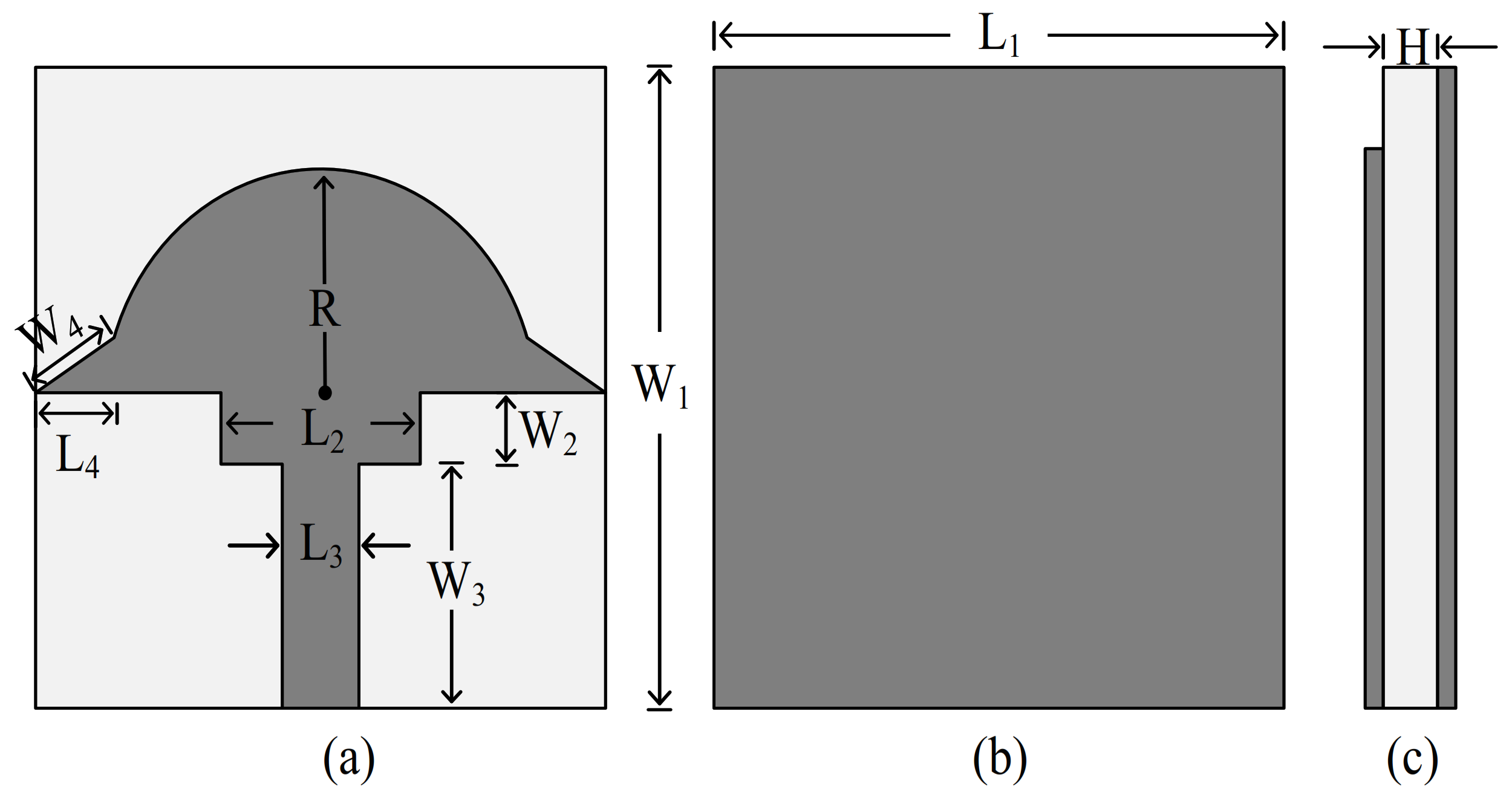
2.1. Antenna Geometery

Figure 1a−c presents the top, back, and side views of the proposed antenna. The antenna design is modeled using Rogers RT/Duroid 5870 with a relative permittivity of 2.33, a loss tangent of 0.0012 and a thickness of 0.79 mm. The overall substrate dimensions are L1 × W1 × H. The antenna geometry consists of a semicircular radiator etched at the top side of the substrate and is designed using copper according to a 113-standard thickness (0.035 mm) with an effective length of λ/2, which is fed using a microstrip line. The final proposed design consists of a semicircular patch antenna with a rectangular stub loaded at the bottom along with two triangular protrusions at the corners of the patch, as illustrated in Figure 1a, whereas the back side of the substrate contains a full ground plane. The simulations of the proposed antenna were performed using a Higher Frequency Structural Simulator (HFSS). In order to achieve the optimal radiation characteristics, various parameters of the antenna were optimized in each design step. The optimized dimensions of the proposed tri-band antenna are as follows: W1 = 8 mm, L1 = 8 mm, H = 0.79 mm, L3 = 0.8 mm, W3 = 3.26 mm, L2 = 1.4 mm, W2 = 0.7 mm, L4 = 0.5 mm, W4 = 1 mm, R = 2.5 mm. The resultant antenna exhibits triband behavior showing resonances at 28 GHz, 38 GHz, and 54 GHz.

2.2. Antenna Design Stages

The final optimized antenna design is obtained in four major steps illustrated in Figure 2. Initially, a circular patch antenna was obtained resonating at a higher frequency of 44 GHz. The circular patch antenna is designed by using well known equations from [22].
The circular patch antenna resonates around 44 GHz with an impedance bandwidth of 43−45 GHz, as exhibited by the reflection coefficient results in Figure 2. In the next step, two identical rectangular slots are etched from the circular radiator resulting in the formation of a semi-circular-shaped radiator. This modification results in widening of the band with bandwidth ranging from 40 GHz to 54 GHz, whereas another band at 30 GHz is also obtained at this step, as depicted in Figure 2. Although two resonant bands were obtained in this step, the band at lower frequency is somewhat narrow and does cover the desired frequency band for 5G communication. In order to obtain the targeted bands, a rectangular shaped stub is loaded at the bottom of semi-circular shaped radiator. The stub loading technique is well known due to its numerous advantages, not limited to improvement of the impedance bandwidth and improved matching at the desired frequency, as explained briefly in [23,24,25]. The stub loaded semi-circular radiator offers tri band operational modes with pass bands of 29.7−33 GHz, 38−40.5 GHz and 52−58 GHz with respective resonances at 30 GHz, 39 GHz, and 54 GHz. Later, optimization is carried out to shift the resonating frequencies towards targeted band spectrums. Through parametric analysis, two triangular shaped protrusions are incorporated at the corners of the semicircular patch to achieve the aforementioned goal. Consequently, three resonances at 28, 38, and 55 GHz are obtained as shown in Figure 2.

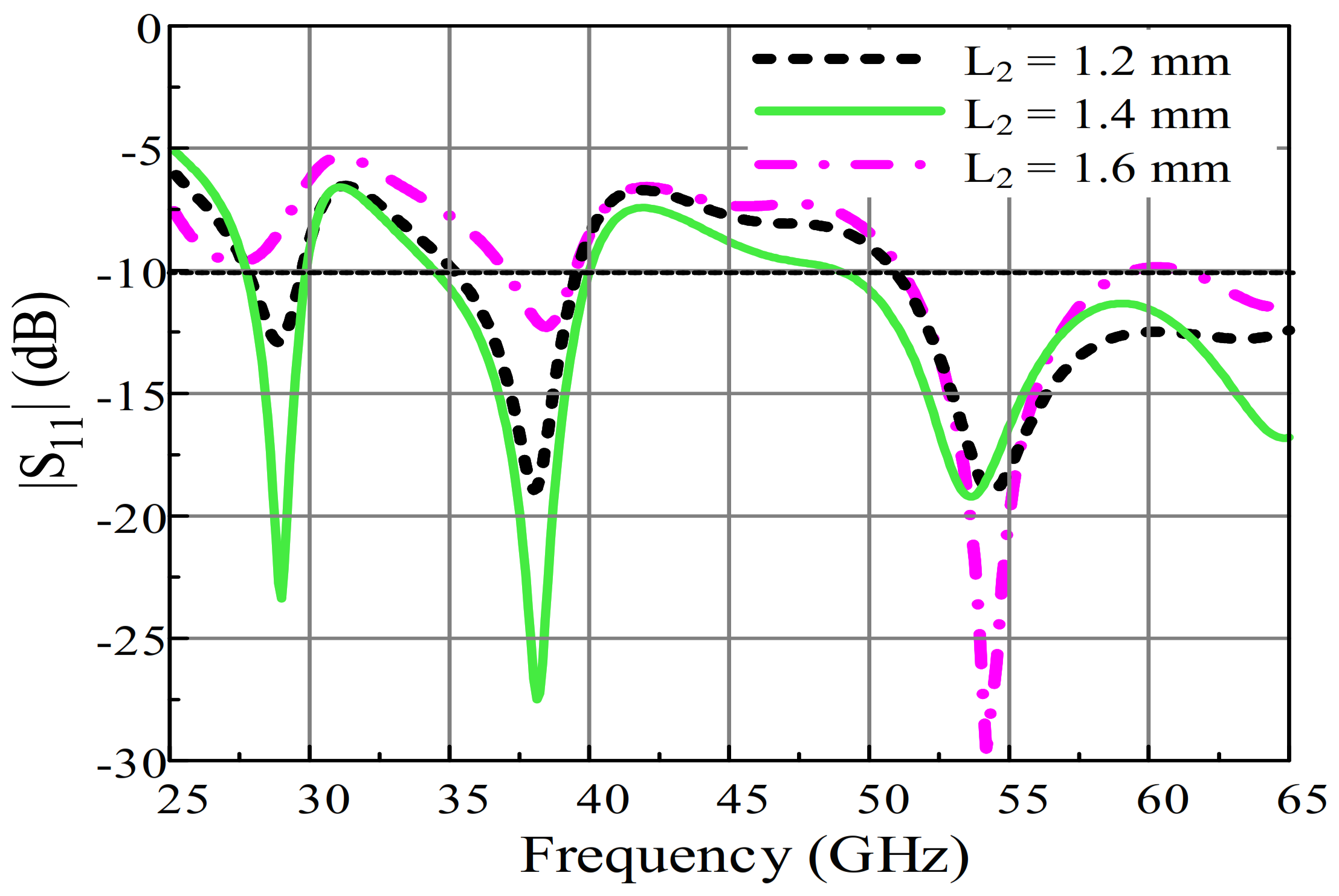
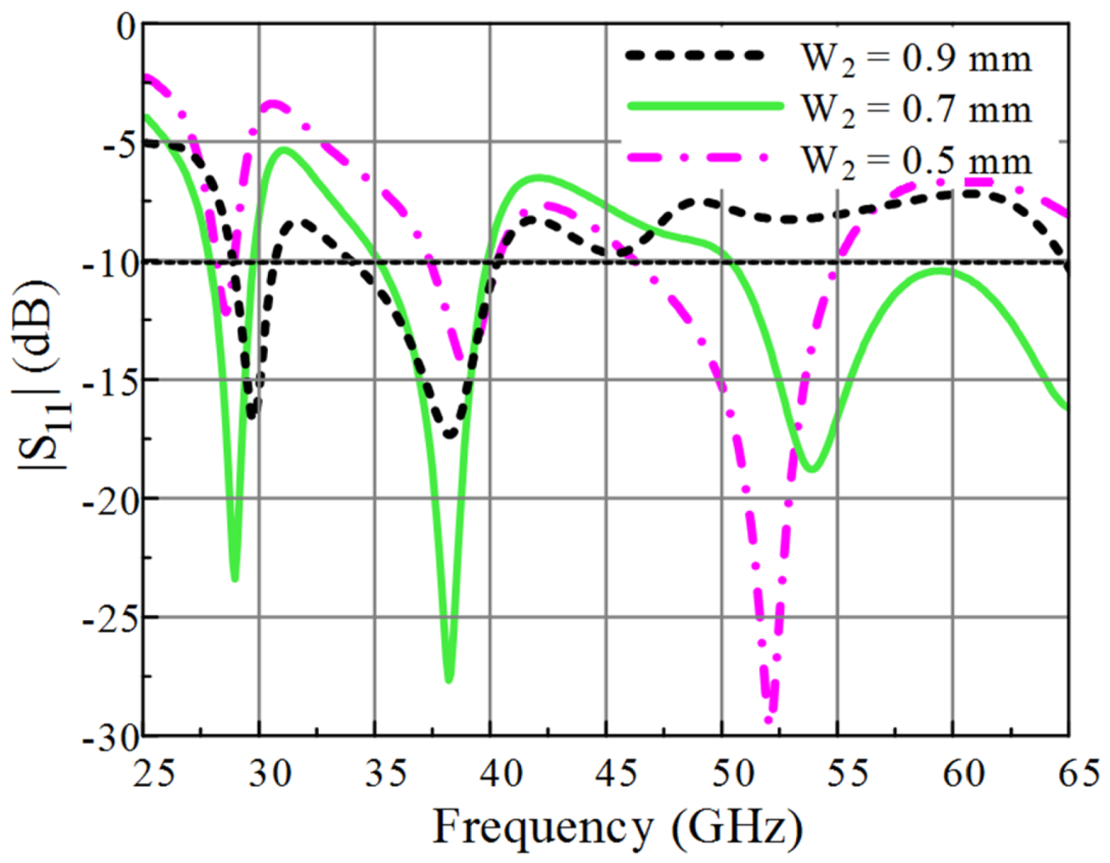
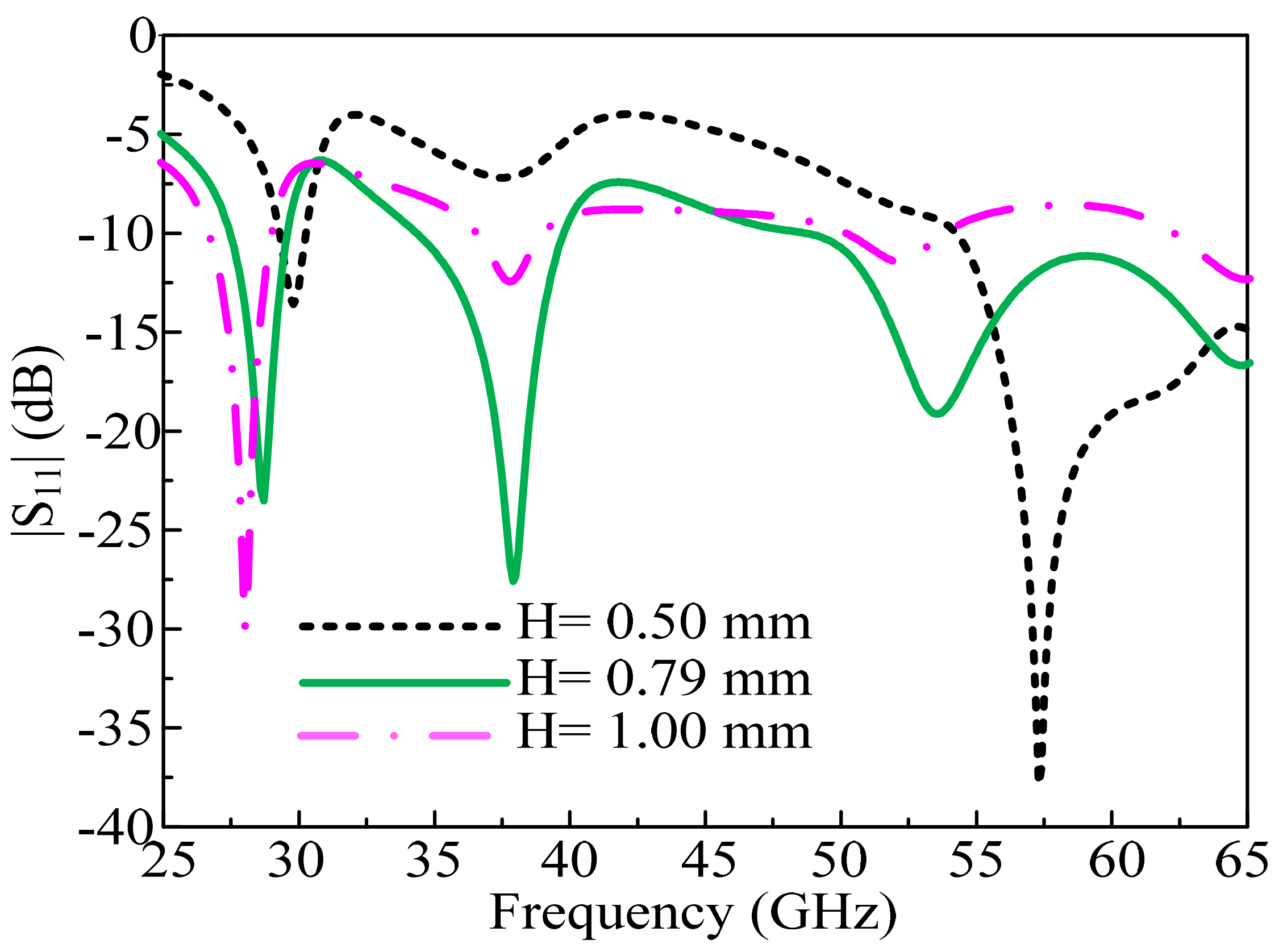
2.3. Parameteric Analysis

To obtain the desired frequency bands with wide bandwidth and to improve the impedance matching, parametric analysis of important parameters is performed. The length (L2) and width (W2) of the stub plays a significant role in designing the antenna in order to achieve the required resonance frequencies along with the wide band and higher impedance matching. If the length of the rectangular stub is set at 1.6 mm, it attains a narrow V-band ranging from 52 GHz to 58 GHz. In addition, mismatching and shifting to undesirable frequencies is observed for other two bands, as depicted in Figure 3. If the value of L2 is reduced to 1.4 mm, the antenna performance shows significant improvement due to increase in impedance matching at resonant bands as well as widening of the V-band being observed. If L2 is further reduced to 1.2 mm, again impedance mismatching and narrowing of the bands occurs. Thus, the optimized value for length of the stub is 1.4 mm, which shows best performance in terms of bandwidth as well as reflection coefficient.
Figure 4 demonstrates the parametric analysis for the width (W2) of the rectangular stub. It is observed from the reflection coefficient curves that at the optimal value of W2 = 0.7 mm, the antenna resonates at 28 GHz, 38 GHz, and 55 GHz frequencies with bandwidth ranging from 27.3 GHz to 29.6 GHz, 34.8 to 39.4 GHz, and 49.8 to 65 GHz. If the value of W2 is increased and fixed at 0.9 mm, adverse effects are noticed in terms of impedance mismatch at the 28 GHz and 38 GHz bands, where only two bands are achieved and resonance at the V-band is lost as the band shifts above −10 dB. As a result, the bandwidth is reduced from 2.3 GHz, 4.6 GHz, and 21.5 GHz to 1 GHz, 3.5 GHz, and 19 GHz, respectively, at 28 GHz, 38 GHz, and 55 GHz. On the other hand, if W2 is set at 0.5 mm, then again narrowing of the bandwidth as well as impedance mismatch is observed. Therefore, it is concluded that the optimal value for W2 is 0.7 mm, which exhibits triband operation with a wide required bandwidth at mm-wave frequencies.
Figure 5 expresses the parametric analysis of thickness of substrate material. It can be observed that, at the optimal value of H = 0.79 mm, the proposed antenna offers tri-band at 28 GHz, 38 GHz and 55 GHz. If the thickness of substrate is reduced to 0.5 mm, it has effects on bandwidth as well as impedance matching. The antenna resonates at 30 GHz and 57 GHz, with bandwidth the ranging from 29 GHz to 31 GHz and 55 GHz to 65 GHz, respectively, as depicted in Figure 5. On other hand, if the thickness of substrate in increased to 1.00 mm, it shifts the obtained band towards the lower side, whereas the V-band is lost. The antenna only resonates for bands from 26 GHz to 30 GHz and 37 GHz to 38 GHz with impedance mismatching, as shown in Figure 5.

2.4. Surface Current Distribution

Figure 6 illustrates the surface current distribution of the proposed antenna at selected resonating frequencies of 28 GHz, 38 GHz, and 54 GHz. It can be observed from Figure 6a,b that the current distribution is highest along the rectangular stub and the triangular protrusions of the semi-circular radiator, representing the larger effective electrical length which justifies the generation of lower resonances at 28 GHz and 38 GHz. Moreover, it can be detected in Figure 6c that, for the selected frequency of 54 GHz, the maximum current is distributed along the bottom of the rectangular stub and feedline which represents the small electrical size and controls the generation of higher band at 54 GHz.

3. Experimental Results and Discussions

Analysis of the proposed antenna performance through various performance metrics is provided in this section with detailed comparison of measured and simulated results. For experimental validation, the antenna prototype was fabricated on a ROGERS 5880 substrate as illustrated in Figure 7a, and measured using 1.85 mm narrow block End Launch Connector by withwave®, with a maximum operating frequency of 67 GHz [26].

3.1. Measurement Setup

The Vector Network Analyzer (VNA) model R&S ZVA110, which has frequency range up to 110 GHz by Rohde & Schwarz, was utilized to verify the reflection coefficient to study and verfiy the frequency domain reflection propoerties of proposed tri-band antenna. For far-field measurement, the shielded RF anechoic chamber was used in order to vadilate the far-field radation characteristics of the proposed design. A standrad horn antenna (SGH-series) with gain of 24 dBi was used as a transmitter while the proposed antenna was used as a receiver to obtain accurate gain measurements. The signal generated by voltage controlled oscillator (VCO) can be effected by transmission losses and open air. To overcome these effects, high gain power amplifiers were used in the measurement setup as they are able to boost the generated signal and efficient transmission of the radio signal was obtained from the transmitter to the receiver.

3.2. S-parameters

The measured and simulated reflection coefficient results of the proposed antenna are demonstrated in Figure 7b. It can be observed that the proposed antenna exhibits triband operational modes with resonances at 28 GHz, 38 GHz, and 54 GHz. The impedance bandwidths of the proposed antenna with reference to |S11| < −10 dB can be observed to range from 27.3 GHz to 29.6 GHz, 34.8 GHz to 40 GHz and 49.8 GHz to 64.8 GHz. The proposed antenna shows significant performance covering the whole band spectrums of 28 GHz and 38 GHz allocated by FCC for 5G mm-wave communication, along with the V-band allocated globally. Thus, an overall good agreement between the simulated and measured results can be observed; nevertheless, the insignificant disagreement is due to errors in the fabrication and measurement apparatus.

3.3. Radiation Pattern

Figure 8a−c depicts the radiation pattern of the proposed antenna at various resonating frequencies. It can be noticed that antenna exhibits broadside radiation pattern at 28 GHz for the H-plane, whereas for the E-plane a slight tilt is observed in the radiation pattern, as shown in Figure 8a. Furthermore, Figure 8b illustrates that, for 38 GHz, a slightly tilted radiation pattern is obtained in the principle E-plane, while in the H-plane a dual beam radiation pattern is formed at angles of ±30°. For 55 GHz, the radiation pattern is directed towards an angle of −30° in E-plane; however, for the H-plane the antenna exhibits a dual beam like radiation pattern, as shown in Figure 8c. It can also be observed that simulated and measured results show good correlation.

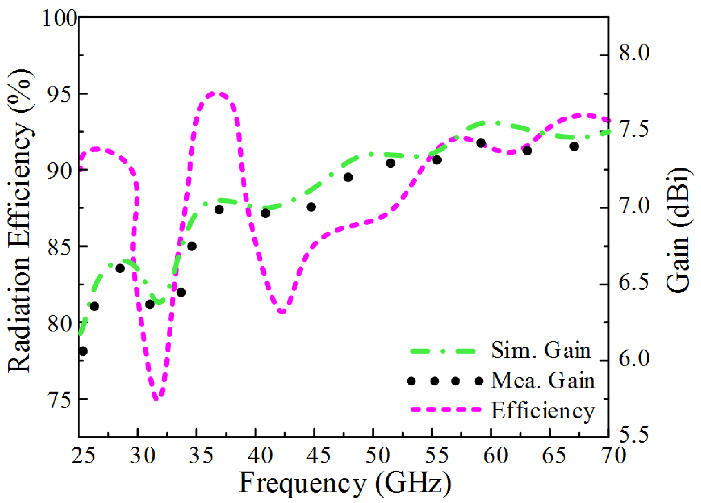
3.4. Gain and Radiation Efficiency

The simulated and measured peak gain along with radiation efficiency is illustrated in Figure 9. The simulated values demonstrate that the proposed antenna attains peak gains of 6.8 dBi, 7.15 dBi and 7.4 dBi at 28 GHz, 38 GHz, and 55 GHz, whereas the measured peak gains are 6.6 dBi, 7.0 dBi and 7.35 dBi at the three resonant frequencies. The radiation efficiency of the proposed antenna can be observed at >85% for all resonating bands, as depicted in Figure 9.

4. Comparison with State-of-the-Art-Works

Table 1 presents the comparison of the proposed antenna with the recently reported literary studies. It can be observed that the presented work offers compact-sized antenna as compared to most of the other works. Even though the antennas reported in [13,14,15] are triband comparatively compact, these antennas exhibit narrow bandwidth and low gain. Additionally, the studies [16,17,18] reported large-sized antennas with dual band operation and a relatively narrow bandwidth. Thus, good radiation characteristics of the proposed triband antenna such as wide bandwidth, significant antenna gain, better radiation efficiency along with simple and compact structure endorse the suitability of the design for communication devices operating in a 5G mm-wave spectrum.

5. Conclusions

A geometrically simple and compact-sized tri-band antenna is presented in this paper. The geometry of the antenna is composed of a semicircular radiator loaded with a rectangular stub and triangular protrusions to achieve the desired tri-bands at the respective frequencies of 28 GHz, 38 GHz, and 54 GHz. The antenna covers the allocated band spectrum for 28 GHz (27.5−28.25 GHz), 38 GHz (36.5−39.25 GHz), and V-band (57−64 GHz) while it has a measured high gain of 6.6−7.35 dBi, moderately stable radiation patterns, and high radiation efficiency. Moreover, comparative analysis of the proposed antenna with state-of-the-art work demonstrates that the proposed antenna is a potential candidate for future communication systems.

Author Contributions

Conceptualization, M.H., S.M.R.J., S.I.N., U.G., S.K., M.A. and I.H.; methodology, M.H., S.M.R.J., S.I.N., U.G., M.A. and I.H.; software, M.H., S.M.R.J. and S.I.N.; validation, M.H., S.M.R.J., S.I.N., U.G., S.K., M.A. and I.H.; formal analysis, M.H., S.M.R.J., S.I.N., U.G., M.A. and I.H.; investigation, M.H., S.M.R.J., S.I.N., U.G. and M.A.; re-sources, M.H., S.M.R.J., S.I.N. and U.G.; data curation, M.H., S.M.R.J., S.I.N., U.G., M.A. and I.H.; writing—original draft preparation, M.H. and S.M.R.J.; writing—review and editing, M.H., S.M.R.J., S.I.N., U.G., S.K., M.A. and I.H.; visualization, M.H., S.M.R.J., S.I.N., U.G. and M.A.; supervision, S.I.N.; project administration, S.I.N., U.G., M.A. and I.H.; funding acquisition, S.K. and M.A. All authors have read and agreed to the published version of the manuscript.

Funding

This project received funding from Universidad Carlos III de Madrid and the European Union’s Horizon 2020 research and innovation program under the Marie Sklodowska-Curie Grant 801538. Furthermore, this work was partially supported by the Researchers Supporting Project number (RSP-2021/58), King Saud University, Riyadh, Saudi Arabia.

Data Availability Statement

All data are included within the manuscript.

Acknowledgments

The authors appreciate financial support from Universidad Carlos III de Madrid and the European Union’s Horizon 2020 research and innovation program under the Marie Sklodowska-Curie Grant 801538. Moreover, this work was partially supported by the Antenna and Wireless Propagation Group (https://sites.google.com/view/awpgrp/home, assessed on 15 August 2021) and from the Researchers Supporting Project number (RSP-2021/58), King Saud University, Riyadh, Saudi Arabia.

Conflicts of Interest

The authors declare no conflict of interest.

References

  1. Iqbal, A.; Altaf, A.; Abdullah, M.; Alibakhshikenari, M.; Limiti, E.; Kim, S. Modified U-Shaped Resonator as Decoupling Structure in MIMO Antenna. Electronics 2020, 9, 1321. [Google Scholar] [CrossRef]
  2. Awan, W.; Naqvi, S.; Ali, W.; Hussain, N.; Iqbal, A.; Tran, H.; Alibakhshikenari, M.; Limiti, E. Design and Realization of a Frequency Reconfigurable Antenna with Wide, Dual, and Single-Band Operations for Compact Sized Wireless Applications. Electronics 2021, 10, 1321. [Google Scholar] [CrossRef]
  3. Awan, W.A.; Naqvi, S.I.; Naqvi, A.H.; Abbas, S.M.; Zaidi, A.; Hussain, N. Design and Characterization of Wideband Printed Antenna Based on DGS for 28 GHz 5G Applications. J. Electromagn. Eng. Sci. 2021, 21, 177–183. [Google Scholar] [CrossRef]
  4. Zahra, H.; Awan, W.; Ali, W.; Hussain, N.; Abbas, S.; Mukhopadhyay, S. A 28 GHz Broadband Helical Inspired End-Fire Antenna and Its MIMO Configuration for 5G Pattern Diversity Applications. Electronics 2021, 10, 405. [Google Scholar] [CrossRef]
  5. Das, P.; Mandal, K.; Lalbakhsh, A. Single-layer polarization-insensitive frequency selective surface for beam reconfigurability of monopole antennas. J. Electromagn. Waves Appl. 2020, 34, 86–102. [Google Scholar] [CrossRef]
  6. Hussain, M.; Awan, I.A.; Rizvi, S.M.; Alibakhshikenari, M.; Falcone, F.; Limiti, E. Simple Geometry Multi-Bands Antenna for Millimeter-Wave Applications at 28 GHz, 38 GHz, and 55 GHz Allocated To 5G Systems. In Proceedings of the 46th International Conference on Infrared, Millimeter and Terahertz Waves (IRMMW-THz), Online Conference, 29 August–3 September 2021; pp. 1–2. [Google Scholar]
  7. Hussain, N.; Jeong, M.-J.; Abbas, A.; Kim, T.-J.; Kim, N. A Metasurface-Based Low-Profile Wideband Circularly Polarized Patch Antenna for 5G Millimeter-Wave Systems. IEEE Access 2020, 8, 22127–22135. [Google Scholar] [CrossRef]
  8. Adibi, S.; Honarvar, M.A.; Lalbakhsh, A. Gain Enhancement of Wideband Circularly Polarized UWB Antenna Using FSS. Radio Sci. 2021, 56, e2020RS007098. [Google Scholar] [CrossRef]
  9. Hussain, M.; Rizvi, S.M.; Abbas, A.; Nadeem, A.; Alam, I.; Iftikhar, A. A Wideband Antenna for V-Band Applications in 5G Communications. In Proceedings of the International Bhurban Conference on Applied Sciences and Technologies (IBCAST), Islamabad, Pakistan, 12–16 January 2021; pp. 1017–1019. [Google Scholar]
  10. Lin, T.-Y.; Chiu, T.; Chang, D.-C. Design of V-Band Wide-Beamwidth Circularly Polarized Wire-Bond Antenna. IEEE Trans. Compon. Packag. Manuf. Technol. 2017, 8, 261–268. [Google Scholar] [CrossRef]
  11. Wu, J.; Na Huang, W.; Cheng, Y.J.; Fan, Y. A broadband high-gain planar array antenna for V-band wireless communication. In Proceedings of the 3rd Asia-Pacific Conference on Antennas and Propagation, Harbin, China, 26–29 July 2014; pp. 309–312. [Google Scholar] [CrossRef]
  12. Kornprobst, J.; Wang, K.; Hamberger, G.; Eibert, T.F. A mm-Wave Patch Antenna with Broad Bandwidth and a Wide Angular Range. IEEE Trans. Antennas Propag. 2017, 65, 4293–4298. [Google Scholar] [CrossRef]
  13. Firdausi, A.; Hakim, G.; Alaydrus, M. Designing a tri-band microstrip antenna for targetting 5g broadband communications. MATEC Web of Conference EDP Sci. 2018, 218, 03015. [Google Scholar] [CrossRef] [Green Version]
  14. Kamal, M.S.; Islam, M.J.; Uddin, M.J.; Imran, A.Z.M. Design of a tri-band microstrip patch antenna for 5G application. In Proceedings of the 2018 International Conference on Computer, Communication, Chemical, Material and Electronic Engineering (IC4ME2), Rajshahi, Bangladesh, 8–9 February 2018; pp. 1–3. [Google Scholar]
  15. Amrutha, G.M.; Sudha, T. Triple Band Antenna for 5G Applications. In Proceedings of the 2018 International Conference on Advances in Computing, Communications and Informatics (ICACCI), Bangalore, India, 19–22 September 2018; pp. 1650–1652. [Google Scholar]
  16. Hasan, N.; Bashir, S.; Chu, S. Dual band omnidirectional millimeter wave antenna for 5G communications. J. Electromagn. Waves Appl. 2019, 33, 1581–1590. [Google Scholar] [CrossRef]
  17. Marzouk, H.M.; Ahmed, M.I.; Shaalan, A.H.A. Novel dual-band 28/38 GHz MIMO antennas for 5G mobile applications. Prog. Electromag. Res. 2019, 93, 103–117. [Google Scholar] [CrossRef] [Green Version]
  18. Rahayu, Y.; Hidayat, M.I. Design of 28/38 GHz dual-band triangular-shaped slot microstrip antenna array for 5G applications. In Proceedings of the 2nd International Conference on Telematics and Future Generation networks (TAFGEN), Kuching, Malaysia, 24–26 July 2018; pp. 93–97. [Google Scholar]
  19. Khan, Z.; Memon, M.H.; Rahman, S.U.; Sajjad, M.; Lin, F.; Sun, L. A Single-Fed Multiband Antenna for WLAN and 5G Applications. Sensors 2020, 20, 6332. [Google Scholar] [CrossRef] [PubMed]
  20. Afzal, M.U.; Esselle, K.P.; Lalbakhsh, A. A Methodology to Design a Low-Profile Composite-Dielectric Phase-Correcting Structure. IEEE Antennas Wirel. Propag. Lett. 2018, 17, 1223–1227. [Google Scholar] [CrossRef]
  21. Ray, M.K.; Mandal, K.; Nasimuddin, N.; Lalbakhsh, A.; Raad, R.; Tubbal, F. Two-Pair Slots Inserted CP Patch Antenna for Wide Axial Ratio Beamwidth. IEEE Access 2020, 8, 223316–223324. [Google Scholar] [CrossRef]
  22. Balanis, C.A. Antenna Theory: Analysis and Design, 3rd ed.; Wiley: Hoboken, NJ, USA, 2005. [Google Scholar]
  23. Mohamadzade, B.; Lalbakhsh, A.; Simorangkir, R.B.V.B.; Rezaee, A.; Hashmi, R.M. Mutual coupling reduction in microstrip array antenna by employing cut side patches and EBG structures. Prog. Electromagn. Res. 2020, 89, 179–187. [Google Scholar] [CrossRef] [Green Version]
  24. Hussain, M.; Mazher, A.; Chaudary, E.; Hussain, B.; Alibakhshikenari, M.; Falcone, F.; Limiti, E. Compact Dual-Band Antenna with High Gain and Simple Geometry for 5G Cellular Communication Operating at 28 GHz and 44 GHz. In Proceedings of the 2021 XXXIVth General Assembly and Scientific Symposium of the International Union of Radio Science (URSI GASS), Rome, Italy, 28 August–4 September 2021; pp. 1–4. [Google Scholar]
  25. Altaf, A.; Iqbal, A.; Smida, A.; Smida, J.; Althuwayb, A.; Kiani, S.H.; Alibakhshikenari, M.; Falcone, F.; Limiti, E. Isolation Improvement in UWB-MIMO Antenna System Using Slotted Stub. Electronics 2020, 9, 1582. [Google Scholar] [CrossRef]
  26. Withwave. Available online: www.withwave209.cafe24.com (accessed on 15 August 2021).
Figure 1. The geometry of the proposed antenna consists of a microstrip feedline and umbrella-shaped patch (a) top view (b) bottom view (c) side view.
Electronics 10 02674 g001
Figure 2. Comparison of return losses of different stages of design of the proposed antenna.
Electronics 10 02674 g002
Figure 3. Parametric analysis performed over the length of the rectangular stub (L2).
Electronics 10 02674 g003
Figure 4. Parametric analysis performed over the width of the rectangular stub (W2).
Electronics 10 02674 g004
Figure 5. Parametric analysis performed over the thickness of the substrate (H).
Electronics 10 02674 g005
Figure 6. The surface current distribution of proposed antenna at the selected frequencies of (a) 28 GHz (b) 38 GHz (c) 54 GHz.
Electronics 10 02674 g006
Figure 7. (a) Hardware prototype of the proposed antenna; (b) comparison of the predicted and measured return losses of the proposed work.
Electronics 10 02674 g007
Figure 8. The gain of the proposed tri-band antenna at (a) 28 GHz (b) 38 GHz (c) 55 GHz.
Electronics 10 02674 g008
Figure 9. Radiation efficiency and gain curves versus operating frequency bands.
Electronics 10 02674 g009
Table 1. Comparison of proposed work with related work.
Ref.Antenna Size
(mm2)
Bandwidth
(GHz)
Operational ModeOperating Frequency
(GHz)
Peak Gain
(dBi)
[13]10 × 5 × 0.513, 5, 3Tri-Band45, 57, 665.6
[14]4 × 5 × 0.20.5, 0.9, 0.4Tri-Band24.4, 28, 386.5, 7, 5
[15]8 × 8 × 1.62.5, 1.6, 7Tri-Band26, 35, 545.8, 4.5, 6
[16]14 × 12 × 0.382.6, 2.1Dual Band28, 381.27, 1.83
[17]55 × 110 × 0.050.8, 1.5Dual Band28, 387.9, 8.2
[18]20 × 20 × 1.954.8, 3.6Dual Band28, 385.7, 7.2
This work8 × 8 × 0.792.3, 5.2, 15Tri-Band28, 38, 556.6, 7.0, 7.35
Publisher’s Note: MDPI stays neutral with regard to jurisdictional claims in published maps and institutional affiliations.

