Article

Transient Stability Enhancement of a Grid-Connected Large-Scale PV System Using Fuzzy Logic Controller

1
Department of Electrical and Electronics Engineering, American International University-Bangladesh (AIUB), 408/1 Kuratoli, Khilkhet, Dhaka 1229, Bangladesh
2
School of Engineering and Technology, Central Queensland University Australia, Melbourne, VIC 3000, Australia
3
Centre for Intelligent Systems, School of Engineering and Technology, Central Queensland University, Brisbane, QLD 4000, Australia
*
Authors to whom correspondence should be addressed.
Electronics 2021, 10(19), 2437; https://doi.org/10.3390/electronics10192437
Submission received: 28 August 2021 / Revised: 1 October 2021 / Accepted: 5 October 2021 / Published: 8 October 2021

Abstract

:
This paper presents a new intelligent control strategy to augment the low-voltage ride-through (LVRT) potential of photovoltaic (PV) plants, and the transient stability of a complete grid system. Modern grid codes demand that a PV plant should be connected to the main power system during network disturbance, providing voltage support. Therefore, in this paper, a novel fuzzy logic controller (FLC) using the controlled cascaded strategy is proposed for the grid side converter (GSC) of a PV plant to guarantee voltage recovery. The proposed FLC offers variable gains based upon the system requirements, which can inject a useful amount of reactive power after a severe network disturbance. Therefore, the terminal voltage dip will be low, restoring its pre-fault value and resuming its operation quickly. To make it realistic, the PV system is linked to the well-known IEEE nine bus system. Comparative analysis is shown—using power system computer-aided design/electromagnetic transients including DC (PSCAD/EMTDC) software—between the conventional proportional–integral (PI) controller-based cascaded strategy and the proposed control strategy to authenticate the usefulness of the proposed strategy. The comparative simulation results indicate that the transient stability and the LVRT capability of a grid-tied PV system can be augmented against severe fault using the proposed FLC-based cascaded GSC controller.

1. Introduction

Due to the global warming issues of fossil fuel-based power stations and the increasing cost of energy generation, the presence of large-scale renewable energy sources (RESs) in current power systems has been increasing over the last decade. Among different types of RESs, PV power plants are among the most popular because they are continuously decreasing in price [1,2,3,4].
According to Refs. [5,6], the global capacity of installed PV systems was 512 GW in 2018 [5], and it will reach about 1.1 TW in 2022. A recent report showed that China, India, the USA, Japan, and Australia are in the top positions, having installed 44.3 GW, 10.8 GW, 10.7 GW, 6.7 GW, and 3.8 GW, respectively, in 2018 [5].
China’s total installed capacity reached 175.4 GW, retaining the country’s market leadership position [5]. Additionally, in the USA, solar energy holds the most significant percentage of RESs [7].

1.1. Motivation

The enormous integration of PV plants into the prevailing power grid introduces issues concerning the entire power system’s stability and reliability [8,9,10,11]; therefore, transmission system operators (TSOs) are directed to revise the existing grid code to ensure the smooth and reliable operation of solar PV-connected grid systems [12].
Low-voltage-ride through (LVRT) capability is one of the major grid code obligations of grid-tied PV systems, requiring a PV system to stay connected during network disturbances, and requiring it to support the grid in restoring its terminal voltage following a disturbance to the nominal value, within a pre-defined time frame as set or programed [13,14,15,16,17].

1.2. Literature Reviews

Several researchers have investigated the characteristics of solar PV systems under network disturbance conditions and have designed several LVRT control strategies accordingly [18,19,20,21,22,23,24,25].
For example, in Ref. [18], a supercapacitor was used in the DC side of a PV system, consuming additional power and eventually compensating for the output power, which augmented the LVRT capability; however, the overall system cost increased with supercapacitor use. In Refs. [19,20], several cascaded proportional–integral (PI) controllers were used to augment the competence and stability of the LVRT. Typically, PI controllers provide fixed gain; however, they cannot operate well under the non-linearities of a PV system, which include a power system’s parameter variations, which can lead to the power system’s instability.
Additionally, the PI controller parameter setting that is used in the cascaded control strategy is cumbersome, especially when it comes to the applications of a power system that are tough to express as a transfer function or a mathematical model. In Refs. [21,22,23,24,25], meta-heuristic algorithms including the whale optimization algorithm [21], the genetic algorithm [22], the Taguchi approach [23], the harmony search algorithm [24], and the salp swarm algorithm [25], were presented for the optimal design of PI controllers in the cascaded control technique. These approaches are effective tools for dealing with non-linearity issues; however, the fine-tuning of numerous PI controllers necessitates complex computational studies and considerable effort. Moreover, a typical PI controller with fixed gain in both the inner and outer loops of the cascaded control technique cannot inject an enormous quantity of reactive power throughout the fault period. Reactive power injection is necessary during the transient state to ensure LVRT capability; thus, the LVRT competency of PV systems cannot be ensured by adopting these techniques.
On the other hand, fuzzy logic controllers (FLCs) have the benefit of using artificial learning to model the system. They can manage the non-linearity of the grid system properly by proving an adjustable gain throughout the transient circumstances and allow for parameter variations. A FLC is reliant on its designer’s expertise in fine-tuning membership functions (MFs) using if–then rules. FLCs have been widely used in the power industry to tackle a variety of issues [26].
In Ref. [27], a fuzzy gain scheduling PI controller was designed to improve the power system’s transient stability; however, the FLC controller required three gains (Kp, Ki, Kd) to be set simultaneously [27], which made the fuzzy rules more challenging and complicated.
Additionally, a FLC was applied to the hybrid power system’s fault current limiter (FCL) to augment the LVRT performance in Ref. [28]. However, the introduction of auxiliary components may increase the overall system’s cost.

1.3. Contributions

In light of the above discussion, this study introduces a new control approach based on FLCs to enhance the LVRT competency of a grid-tied PV station/plant. The main contributions and novelties of this study are listed below:
(1)
A new FLC is incorporated along with the traditional PI controller in the inner loop of the cascaded control technique to enrich the LVRT proficiency of a PV system. Due to its variable gain, the proposed FLC will inject an efficient quantity of reactive power to maintain the terminal voltage at pre-fault value. The single FLC in a cascaded controller will offer less computation burden and is cheaper than having many FLCs in the cascaded controller [29].
(2)
A comparative analysis is presented, comparing the proposed control strategy with the conventional control strategy developed in Ref. [30]; this shows the importance of the proposed control strategy, taking the severe three-line-to-ground (3LG) fault into account.
(3)
Design procedures of the proposed PV system, protection system, and maximum power point tracking (MPPT) system are also presented in detail.
(4)
Finally, the transient stability of the grid system both for the proposed and for the conventional controllers of the PV station/plant is judged by transient stability index computation [31]. This is one of the prominent aspects of this paper.

1.4. Organization

The remainder of the paper is arranged as follows: Section 2 describes the PV power plant model with the proposed controller; Section 3 shows the simulation results with detailed analysis and discussion; Section 4 presents the stability index computation; and Section 5 concludes, providing some future research directives of this research work.

2. Design of a PV Power Station

An overall block diagram of a PV system and its control method is presented in Figure 1. A PV panel is attached to the grid using a boost converter and a grid side converter (GSC). The converters are designed using insulated gate bipolar transistors (IGBTs). The boost converter transforms the uncontrolled DC voltage into controlled DC voltage, and the GSC transforms this controlled DC voltage into grid-appropriate AC voltage.
The boost converter and the GSC are operated by the boost converter and the grid side controller, respectively. The converter controller generates suitable gate signals with the help of pulse width modulation (PWM) techniques for the IGBTs. The detailed mechanisms of the control methods are discussed in Section 2.2, Section 2.3 andSection 2.4.

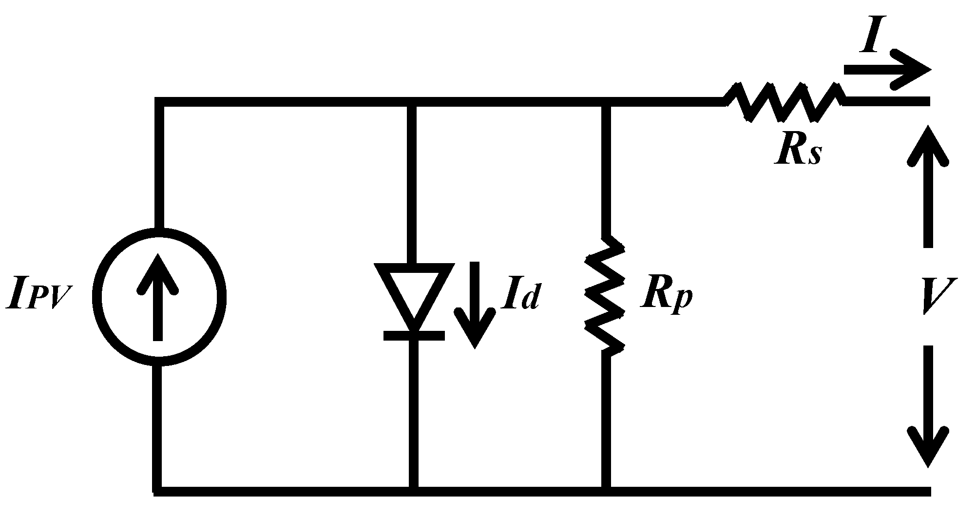
2.1. PV Array Design

The PV array is designed using series and parallel combinations of PV modules. Figure 2 shows a single diode PV model, which is usually used to represent a single PV cell because of its accuracy and simplicity. The model is comprised of a controlled current source, parallel diodes, and two resistances. The two resistances (i.e., parasitic) represent the losses [32].
The relationship between the current (I) and the voltage (V) of a PV module can be represented by the following non-linear equation [33,34,35,36,37]:
I = I P V I o [ exp ( V + R s I a V t ) 1 ] V + R s I R p
Here, IPV = the current of the photovoltaic, Io = the reverse saturation current of the diode, a = the identity factor of the diode, Rp = parallel resistance, and Rs = series resistance.
The mathematical model of a single diode PV module, considering actual and nominal conditions, is adequately presented in Ref. [33]. To build a 50 MW PV station, the Kyocera KC200GT PV module is adopted, where a single module has the maximum power (Pmax) = 200.143 W, maximum voltage (Vmp) = 26.3 V, and maximum current (Imp = 7.6 A), respectively. The parameters of the aggregated PV model are listed in Table 1. The I-V and P-V characteristic curves of the designed PV array are presented in Figure 3.

2.2. Boost Converter Controller and MPPT

As discussed in earlier sections, a boost converter is added to raise the output DC voltage and to obtain the maximum power from the PV panel. This mechanism can be achieved by adjusting the output voltage (Vo) of a PV panel according to ambient temperature and irradiance. A boost converter controller is presented in Figure 4. This controller uses a fractional open circuit voltage algorithm to achieve maximum power.
The duty cycle reference (Dref) for the boost controller can be expressed as follows [38]:
D r e f = 1 N M K m p V o c _ p i l o t V o
Here, Voc_pilot = the open circuit voltage of the pilot module and Kmp = the proportional constant. The optimum value of the KC200GT solar module is 0.8023 [38].
In Figure 4, two separate PI controller loops are incorporated to operate the boost converter. The upper loop ensures MPPT operation, whereas the lower loop will activate during the fault period; this is because, in a fault condition, the DC-Link voltage (Vdc) will rise beyond the rated value. Therefore, the DC power cannot be injected into the grid via an inverter system. During this transient period, the lower controller will protect the DC-Link circuit by maintaining the DC voltage at a pre-defined reference level (1.05 pu) with the help of a comparator circuit.

2.3. Proposed GSC Controller

The proposed cascaded GSC controller, based on a conventional PI controller and a FLC, is presented in Figure 5. It is designed using the rotating dq frame of reference. A phase-locked loop (PLL) is incorporated to generate a transformation angle (Ɵ) for the dq axis. This control technique consists of the outer and inner loops. The outer loops regulate the PV station’s terminal voltage (Vg) and Vdc at a constant level (1.2 kV). The inner loops regulate the dq axis currents of the converter. Three PI controllers and one FLC are used in this GSC control strategy to track the error signals. The reason for using one FLC in the inner loop is to inject more reactive power during the fault period, so that the Vg can resume its regular operation quickly after any fault event. This happens because the FLC can deliver adjustable gain, depending upon system parameters during the fault period. The Taguchi method is utilized in this work for the optimal design of PI controllers in a cascaded control system [23].
A comparator is also embedded in the lower portion of the proposed GSC controller. During the fault period, the active power cannot be transferred to the grid system. When the Vg is less than 0.9 pu, this comparator triggers a zero signal; thus, active power injection becomes zero. This comparator also ensures maximum reactive power injection during fault events by preserving the apparent power rating of the converter within its maximum limit.
Finally, the generated reference dq axis voltage can be transformed into three-phase reference voltage, which is compared with the high frequency carrier wave to generate the necessary gate signals to drive IGBTs.

2.4. Proposed FLC Design

The power system is non-linear in characteristics and subject to network disturbances; therefore, a FLC is used, as shown in Figure 5, to deal with non-linearities. The FLC has an insensitivity to fault due to its variable gain. To design the FLC for a GSC controller, as shown in Figure 6, the error of the d-axis current (eId) and the change in the error of eId (d(eId)/dt) are employed as input; whereas, the output employs d-axis reference voltage (Vd*). Here, 1/z is one sampling of time delay. The basic structure of the FLC is presented in Figure 6, where it is mainly composed of fuzzification, fuzzy inference, and defuzzification.
In fuzzification, two inputs are converted to fuzzy sets between [0, 1] with the help of MFs. The MFs for the input and output are presented in Figure 7. In this study the triangular MF, including overlap, is used, and it is composed of five linguistic variables as follows: negative big (NG), negative small (NS), zero (Z), positive small (PS), and PB (positive big), respectively.
The grade of input MFs can be obtained as follows [39]:
μ ( x ) = [ w 2 ( x m ) ] / 2
where µ(x) is the value of grade of membership, w is the width, m is the coordinate of the point at which the grade of membership is 1, and x is the value of the input variable.
One of the most common MFs in practice is the triangle MF. Straight lines are used to construct triangular MFs. MFs with straight lines have the benefit of being simple [40].
The rule-based block basically consists of if–then conditional statements, as given below:
IF <eId is NS> and <d(eId)/dt is Z> THEN <ΔVd* is PS>;
IF < eId is PS> and <d(eId)/dt is NS> THEN <ΔVd* is Z>.
The twenty-five rules’ data are presented in Table 2, and these are the data used in this research work.
In this work, Mamdani’s max–min method is used for inference mechanisms [41]. The center of gravity method is used for defuzzification to obtain ΔVd* due to its simplicity [42], which is given by following equation:
Δ V d * = i = 1 N μ i C i i = 1 N μ i
where N is the total number of rules, µi is the membership grade for ith rule, and Ci is the coordinate corresponding to the maximum value of the respective consequent membership function.

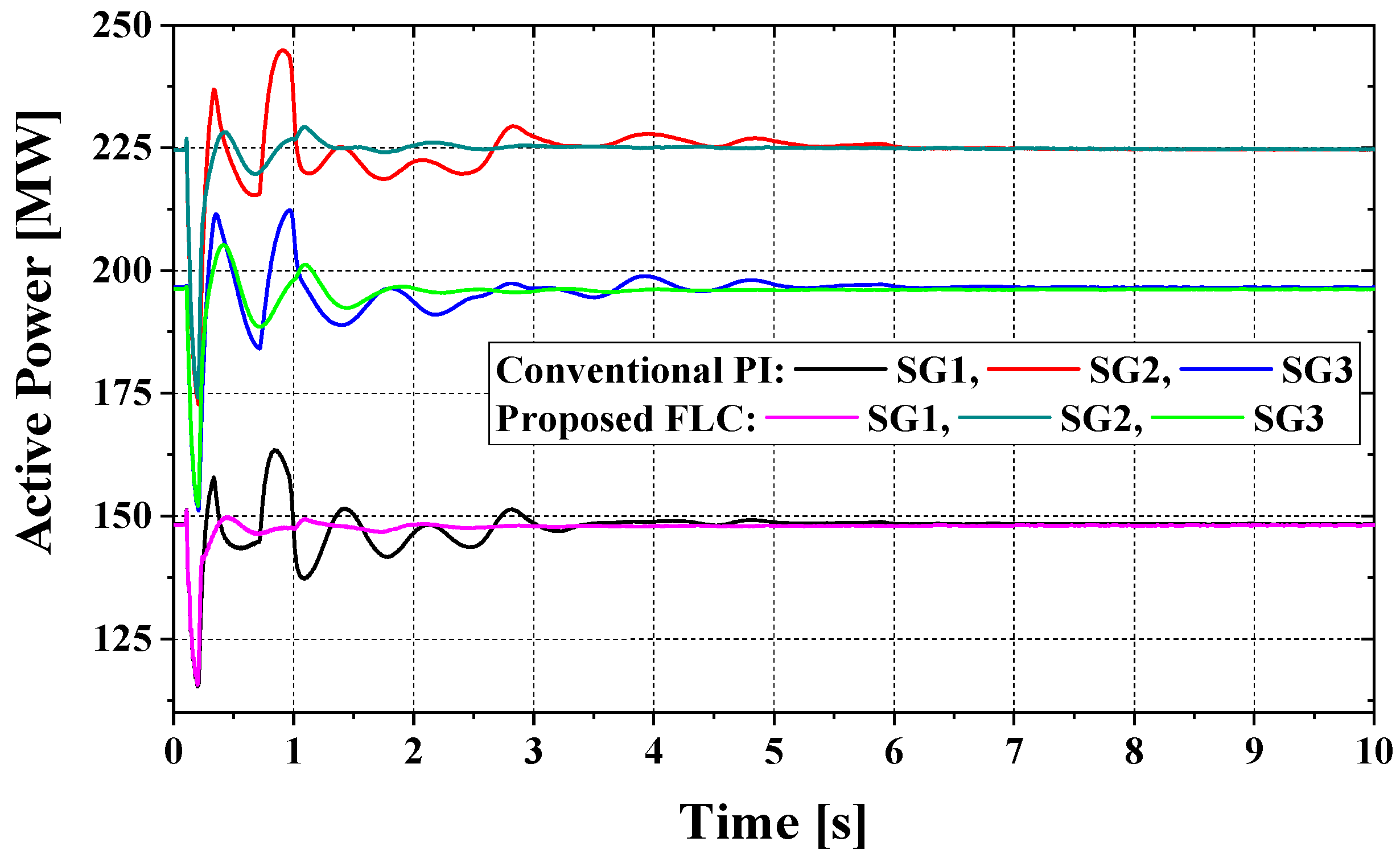
3. Simulation Results and Discussion

The modified version of the IEEE nine bus power plant model, depicted in Figure 8, was used for a simulation study which was conducted using the PSCAD/EMTDC software suites. Three synchronous generators (SGs), three loads, and six transmission lines formed the primary system. In this model there were three power plants; two were thermal-based power stations (SG1 and SG2) and one was a hydro-based power station (SG3).
In addition, the automatic generation control (AGC) technique was adopted in SG1 and SG3; however, was SG2 directed as the governor free control (GF). The governor models, AGC method, and exciter model used in this work were adopted from Ref. [43]. The capacities of the individual conventional power plants were 1.5, 2.5, and 2.0 pu, respectively, and the parameters for each SG were taken from Ref. [44]. Finally, a PV plant was linked to bus 5, using transmission lines and transformers. The rating of the PV station is 0.5 pu.
The simulation time step 20 μs was selected to acquire precise results. To boost the power system’s stability and reliability, the grid codes of various countries were retained. The primary differences between several grid codes are minor; therefore, in this study, the LVRT attributes are based on E.ON Netz (German grid codes) [17,45]. The ability of the proposed FLC system is validated by subjecting the test system to the symmetrical 3LG fault, adjacent to bus 11 of Figure 8. Finally, the outcomes are compared with the conventional PI-based cascaded control mechanism [30].
The 3LG fault was employed in the system model at 0.1 s and it lasted for 0.1 s (5 cycles). The circuit breakers (CBs) were tripped at 0.2 s and closed again at 1 s, assuming the 3LG fault was already cleared.
Figure 9 shows the impact of the 3LG fault on terminal voltage of the PV system and the response of the control system in maintaining terminal voltage. The terminal voltage falls very quickly in conventional cases once a fault occurs. However, the voltage dip in the proposed case is very small because the proposed FLC-controlled GSC of the PV system injects enough reactive power to sustain the grid. The reactive power injection capability for both cases is shown in Figure 10. Figure 11 presents the active power profile at bus 10. It has been observed that a secondary power drop occurs in the conventional PI-controlled GSC case, whereas, it is more stable in the proposed FLC-controlled GSC case. Even though both cases follow the LVRT grid codes by maintaining stability within 1.5 s, the control system response is very fast and has low fluctuation in the proposed case.
The rotor speed and active power profile of the SGs of the main power system have less fluctuation in the proposed case; this is due to an active power injection that fluctuates less during the fault period, as shown in Figure 12 and Figure 13. Figure 14 presents the power angle response of SGs. After the fault, it is observed that the power angle response fluctuates more in the conventional case than in the proposed case. Additionally, the frequency response of the entire power system is more stable in the proposed case than in the conventional case, as depicted in Figure 15.
From the above discussion, it is evident that the proposed technique shows a significantly higher performance and higher robustness than the conventional case.

4. Transient Stability Evaluation

The transient stability of the complete system is evaluated using a transient stability index (Wc) [31,46,47], which is defined as follows:
W c ( s ) = 0 T | d d t W t o t a l | d t / s y s t e m b a s e p o w e r
Here, system base power = the sum of all the rated capacities of conventional SGs, T = simulation time (10 s), and Wtotal = total kinetic energy. Wtotal is computed using the rotor speed of each SG as follows:
W t o t a l = i = 1 N W i ( J )
W i = 1 2 J i ω m i 2 ( J )
J i = 2 H i ω 2 M V A r a t i n g ( e a c h g e n e r a t o r ) × 10 6 ( kg · m 2 )
Here, N = the number of SGs, Wi = the kinetic energy of an individual SG, Ji = the moment of inertia of a particular SG, ωmi = the rotor angular velocity of a particular SG in mechanical rad/s, ω = 2πf is the synchronous speed in rad/s, and Hi = the inertia constant of an individual SG.
The lower the value of Wc, the better the system’s transient stability. The Wc value is lower in the proposed case compared with the conventional case, as indicated in Figure 16, which validates the importance and accuracy of the proposed FLC-controlled GSC controller.

5. Conclusions

This paper proposed a new control mechanism, based on the FLC, for a PV station to augment transient stability in terms of LVRT competence. The FLC offers variable gain depending upon the system’s parameters, helping to inject an adequate amount of reactive power to resume the terminal voltage to its pre-fault condition. The system response of the proposed mechanism complies with all the international LVRT grid codes, which subjects the system to the 3LG fault. The simulation results were compared with those of the conventional controller to verify the proposed FLC-controlled GSC controller. Based on the simulation results and the performance evaluations, the following features of the proposed approach are noteworthy:
  • The proposed technique provides a faster response and increased accuracy in maintaining the terminal voltage of the PV plant and the transient stability of the entire system.
  • The proposed FLC-controlled GSC controller offers an almost negligible voltage dip after a severe network fault.
  • The proposed control method deals with the system’s non-linearities more effectively.
Therefore, the proposed strategy can be incorporated with the grid-tied PV system for sustainable grid networks. This study accounts for a constant load, constant solar irradiance, and constant cell temperature. In the future, a variable load, variable solar irradiance, and variable cell temperature can be considered. Additionally, the adaptive neuro-fuzzy-based control strategy can be applied in the place of a FLC to automatically scale the MFs with the GSC controller of a PV system.

Author Contributions

M.R.H., E.J., M.A.M. and N.D. developed theoretical concepts and designed the proposed grid-tied GSC controller of a PV system. M.R.H. and E.J. executed the simulation studies and wrote the manuscript. All authors have read and agreed to the published version of the manuscript.

Funding

This research received no external funding.

Conflicts of Interest

The authors declare no conflict of interest.

References

  1. Islam, G.; Muyeen, S.M.; Al-Durra, A.; Hasanien, H.M. RTDS Implementation of an Improved Sliding Mode Based Inverter Controller for PV System. ISA Trans. 2016, 62, 50–59. [Google Scholar] [CrossRef]
  2. Mojallal, A.; Lotfifard, S. Enhancement of Grid Connected PV Arrays Fault Ride Through and Post Fault Recovery Performance. IEEE Trans. Smart Grid 2019, 10, 546–555. [Google Scholar] [CrossRef]
  3. Qais, M.H.; Hasanien, H.M.; Alghuwainem, S. Identification of Electrical Parameters for Three-Diode Photovoltaic Model Using Analytical and Sunflower Optimization Algorithm. Appl. Energy 2019, 250, 109–117. [Google Scholar] [CrossRef]
  4. Choi, U.-M. Study on Effect of Installation Location on Lifetime of PV Inverter and DC-to-AC Ratio. IEEE Access 2020, 8, 86003–86011. [Google Scholar] [CrossRef]
  5. Trends in Photovoltaic Applications 2019, International Energy Agency. Available online: https://iea-pvps.org/ (accessed on 22 May 2021).
  6. Global Market Outlook: For Solar Power/2019–2023. Available online: https://www.solarpowereurope.org/ (accessed on 22 May 2021).
  7. Lai, C.S.; Jia, Y.; Lai, L.L.; Xu, Z.; McCulloch, M.D.; Wong, K.P. A Comprehensive Review on Large-Scale Photovoltaic System with Applications of Electrical Energy Storage. Renew. Sustain. Energy Rev. 2017, 78, 439–451. [Google Scholar] [CrossRef]
  8. Eftekharnejad, S.; Vittal, V.; Heydt, G.T.; Keel, B.; Loehr, J. Impact of Increased Penetration of Photovoltaic Generation on Power Systems. IEEE Trans. Power Syst. 2013, 28, 893–901. [Google Scholar] [CrossRef]
  9. Xiao, Q.; Zhao, K.; Jiang, W.; Zhu, S. The Effect of Large-Scale PV Power on Stability of Power System. In Proceedings of the 2018 2nd IEEE Advanced Information Management, Communicates, Electronic and Automation Control Conference (IMCEC), Xi’an, China, 25–27 May 2018; pp. 1173–1177. [Google Scholar]
  10. Anzalchi, A.; Sarwat, A. Overview of Technical Specifications for Grid-Connected Photovoltaic Systems. Energy Convers. Manag. 2017, 152, 312–327. [Google Scholar] [CrossRef]
  11. Liu, S.; Liu, P.X.; Wang, X. Stability Analysis of Grid-Interfacing Inverter Control in Distribution Systems with Multiple Photovoltaic-Based Distributed Generators. IEEE Trans. Ind. Electron. 2016, 63, 7339–7348. [Google Scholar] [CrossRef]
  12. Brooks, D.L.; Patel, M. Panel: Standards Amp; Interconnection Requirements for Wind and Solar Generation NERC Integrating Variable Generation Task Force. In Proceedings of the 2011 IEEE Power and Energy Society General Meeting, Detroit, MI, USA, 24–28 July 2011; pp. 1–3. [Google Scholar]
  13. Yongning, C.; Yan, L.; Zhen, L.; Ziyu, C.; Hongzhi, L. Study on Grid-Connected Renewable Energy Grid Code Compliance. In Proceedings of the 2019 IEEE Sustainable Power and Energy Conference (iSPEC), Beijing, China, 21–23 November 2019; pp. 72–75. [Google Scholar]
  14. RajaMohamed, S.; Jeyanthy, P.A.; Devaraj, D.; Bouzguenda, M. Performance Comparison of Active and Passive LVRT Strategies for Grid Connected PV Systems. In Proceedings of the 2019 IEEE International Conference on Intelligent Techniques in Control, Optimization and Signal Processing (INCOS), Tamilnadu, India, 11–13 April 2019; pp. 1–5. [Google Scholar]
  15. Mirhosseini, M.; Agelidis, V.G. Performance of Large-Scale Grid-Connected Photovoltaic System under Various Fault Conditions. In Proceedings of the 2013 IEEE International Conference on Industrial Technology (ICIT), Cape Town, South Africa, 25–28 February 2013; pp. 1775–1780. [Google Scholar]
  16. Islam, S. Challenges and Opportunities in Grid Connected Commercial Scale PV and Wind Farms. In Proceedings of the 2016 9th International Conference on Electrical and Computer Engineering (ICECE), Dhaka, Bangladesh, 20–22 December 2016; pp. 1–7. [Google Scholar]
  17. E. ON NETZ GmbH. Grid Connection Regulation for High and Extra High Voltage; E. ON NETZ GmbH: Essen, Germany, 2006. [Google Scholar]
  18. Tian, H.; Gao, F.; Ma, C. Novel Low Voltage Ride through Strategy of Single-Stage Grid-Tied Photovoltaic Inverter with Supercapacitor Coupled. In Proceedings of the 7th International Power Electronics and Motion Control Conference, Harbin, China, 2–5 June 2012; Volume 2, pp. 1188–1192. [Google Scholar]
  19. El Moursi, M.S.; Xiao, W.; Kirtley, J.L., Jr. Fault Ride through Capability for Grid Interfacing Large Scale PV Power Plants. IET Gener. Transm. Distrib. 2013, 7, 1027–1036. [Google Scholar] [CrossRef]
  20. Kawabe, K.; Tanaka, K. Impact of Dynamic Behavior of Photovoltaic Power Generation Systems on Short-Term Voltage Stability. IEEE Trans. Power Syst. 2015, 30, 3416–3424. [Google Scholar] [CrossRef]
  21. Hasanien, H.M. Performance Improvement of Photovoltaic Power Systems Using an Optimal Control Strategy Based on Whale Optimization Algorithm. Electr. Power Syst. Res. 2018, 157, 168–176. [Google Scholar] [CrossRef]
  22. Hasanien, H.M.; Muyeen, S.M. Design Optimization of Controller Parameters Used in Variable Speed Wind Energy Conversion System by Genetic Algorithms. IEEE Trans. Sustain. Energy 2012, 3, 200–208. [Google Scholar] [CrossRef]
  23. Hasanien, H.M.; Muyeen, S.M. A Taguchi Approach for Optimum Design of Proportional-Integral Controllers in Cascaded Control Scheme. IEEE Trans. Power Syst. 2013, 28, 1636–1644. [Google Scholar] [CrossRef] [Green Version]
  24. Ambia, M.N.; Hasanien, H.M.; Al-Durra, A.; Muyeen, S.M. Harmony Search Algorithm-Based Controller Parameters Optimization for a Distributed-Generation System. IEEE Trans. Power Deliv. 2015, 30, 246–255. [Google Scholar] [CrossRef]
  25. Elazab, O.S.; Debouza, M.; Hasanien, H.M.; Muyeen, S.M.; Al-Durra, A. Salp Swarm Algorithm-Based Optimal Control Scheme for LVRT Capability Improvement of Grid-Connected Photovoltaic Power Plants: Design and Experimental Validation. IET Renew. Power Gener. 2020, 14, 591–599. [Google Scholar] [CrossRef]
  26. Hasanien, H.M.; Matar, M. A Fuzzy Logic Controller for Autonomous Operation of a Voltage Source Converter-Based Distributed Generation System. IEEE Trans. Smart Grid 2015, 6, 158–165. [Google Scholar] [CrossRef]
  27. Chaiyatham, T.; Ngamroo, I. Improvement of Power System Transient Stability by PV Farm with Fuzzy Gain Scheduling of PID Controller. IEEE Syst. J. 2017, 11, 1684–1691. [Google Scholar] [CrossRef]
  28. Hossain, M.K.; Ali, M.H. Transient Stability Augmentation of PV/DFIG/SG-Based Hybrid Power System by Nonlinear Control-Based Variable Resistive FCL. IEEE Trans. Sustain. Energy 2015, 6, 1638–1649. [Google Scholar] [CrossRef]
  29. Soliman, M.A.; Hasanien, H.M.; Azazi, H.Z.; El-Kholy, E.E.; Mahmoud, S.A. An Adaptive Fuzzy Logic Control Strategy for Performance Enhancement of a Grid-Connected PMSG-Based Wind Turbine. IEEE Trans. Ind. Inf. 2019, 15, 3163–3173. [Google Scholar] [CrossRef]
  30. Ahmed, A.; Hazari, M.R.; Jahan, E.; Mannan, M.A. A Robust Control Strategy to Improve Low Voltage Ride-Through of a Grid-Connected Photovoltaic System. Int. J. Power Energy Syst. 2021, 41, 9–16. [Google Scholar]
  31. Yagami, M.; Murata, T.; Tamura, J. An Analysis of Optimal Reclosing for Enhancement of Transient Stability. Electr. Eng. Jpn. 2004, 147, 32–39. [Google Scholar] [CrossRef]
  32. Khanna, V.; Das, B.K.; Bisht, D.; Vandana; Singh, P.K. A Three Diode Model for Industrial Solar Cells and Estimation of Solar Cell Parameters Using PSO Algorithm. Renew. Energy 2015, 78, 105–113. [Google Scholar] [CrossRef]
  33. Hasanien, H.M. An Adaptive Control Strategy for Low Voltage Ride Through Capability Enhancement of Grid-Connected Photovoltaic Power Plants. IEEE Trans. Power Syst. 2016, 31, 3230–3237. [Google Scholar] [CrossRef]
  34. Hasanien, H.M. Shuffled Frog Leaping Algorithm for Photovoltaic Model Identification. IEEE Trans. Sustain. Energy 2015, 6, 509–515. [Google Scholar] [CrossRef]
  35. Mahmoud, Y.A.; Xiao, W.; Zeineldin, H.H. A Parameterization Approach for Enhancing PV Model Accuracy. IEEE Trans. Ind. Electron. 2013, 60, 5708–5716. [Google Scholar] [CrossRef]
  36. Kadri, R.; Gaubert, J.-P.; Champenois, G. An Improved Maximum Power Point Tracking for Photovoltaic Grid-Connected Inverter Based on Voltage-Oriented Control. IEEE Trans. Ind. Electron. 2011, 58, 66–75. [Google Scholar] [CrossRef]
  37. Kiani, A.T.; Nadeem, M.F.; Ahmed, A.; Khan, I.; Elavarasan, R.M.; Das, N. Optimal PV Parameter Estimation via Double Exponential Function-Based Dynamic Inertia Weight Particle Swarm Optimization. Energies 2020, 13, 4037. [Google Scholar] [CrossRef]
  38. Islam, G.M.S.; Al-Durra, A.; Muyeen, S.M.; Tamura, J. A Robust Control Scheme to Enhance the Stability of a Grid-Connected Large Scale Photovoltaic System. In Proceedings of the PES T D 2012, Orlando, FL, USA, 7–10 May 2012; pp. 1–6. [Google Scholar]
  39. Driankov, D.; Hellendoorn, H.; Reinfrank, M. An Introduction to Fuzzy Control; Springer: Berlin/Heidelberg, Germany, 1993. [Google Scholar]
  40. Sadollah, A. Introductory Chapter: Which Membership Function is Appropriate in Fuzzy System? In Fuzzy Logic Based in Optimization Methods and Control Systems and its Applications; InTech: London, UK, 2018. [Google Scholar]
  41. Mamdani, E.H. Application of Fuzzy Algorithms for Control of Simple Dynamic Plant. Proc. Inst. Electr. Eng. 1974, 121, 1585–1588. [Google Scholar] [CrossRef]
  42. Bose, B.K. Modern Power Electronics and AC Drives; Prentice Hall PTR: Hoboken, NJ, USA, 2002. [Google Scholar]
  43. Kundur, P. Power System Stability & Control; McGraw-Hill Inc.: New York, NY, USA, 1994. [Google Scholar]
  44. Hazari, M.R.; Mannan, M.A.; Muyeen, S.M.; Umemura, A.; Takahashi, R.; Tamura, J. Stability Augmentation of a Grid-Connected Wind Farm by Fuzzy-Logic-Controlled DFIG-Based Wind Turbines. Appl. Sci. 2018, 8, 20. [Google Scholar] [CrossRef] [Green Version]
  45. Mahmud, S.M.I.; Abdul Mannan, M.; Hazari, M.R. Design and Performance Analysis of a PV Control Scheme to Improve LVRT of Hybrid Power System. AIUB J. Sci. Eng. 2021, 20, 20–26. [Google Scholar]
  46. Yagami, M.; Shibata, S.; Murata, T.; Tamura, J. An Analysis of Superconducting Fault Current Limiter for Stabilization of Synchronous Generators in Multi-Machine System. IEEJ Trans. Power Energy 2003, 123, 133–142. [Google Scholar] [CrossRef] [Green Version]
  47. Hazari, M.R.; Jahan, E.; Hossain, C.A.; Abdul Mannan, M.; Umemura, A.; Takahashi, R.; Tamura, J. Stabilization Control of Power System with Large-Scale Wind Farm by Using DFIG Considering Grid Codes. In Proceedings of the 2019 International Conference on Robotics, Electrical and Signal Processing Techniques (ICREST), Dhaka, Bangladesh, 10–12 January 2019; pp. 102–107. [Google Scholar]
Figure 1. Control mechanism of a grid-tied PV power station/plant.
Electronics 10 02437 g001
Figure 2. Equivalent circuit diagram of a single diode PV module.
Electronics 10 02437 g002
Figure 3. Characteristic curves of a 50 MW PV station.
Electronics 10 02437 g003
Figure 4. Boost converter controller of a PV plant.
Electronics 10 02437 g004
Figure 5. Proposed FLC-based cascaded GSC controller.
Electronics 10 02437 g005
Figure 6. Structure of the proposed FLC.
Electronics 10 02437 g006
Figure 7. Membership functions of an FLC.
Electronics 10 02437 g007
Figure 8. System model of a modified IEEE nine bus power plant model.
Electronics 10 02437 g008
Figure 9. Terminal voltage profile of the conventional and proposed PV plants at bus 10.
Electronics 10 02437 g009
Figure 10. Reactive power profile of the conventional and proposed PV plants at bus 10.
Electronics 10 02437 g010
Figure 11. Active power profile of the conventional and proposed PV plants.
Electronics 10 02437 g011
Figure 12. Rotor speed profile of the SGs.
Electronics 10 02437 g012
Figure 13. Active power profile of the SGs.
Electronics 10 02437 g013
Figure 14. Power angle profile of the SGs.
Electronics 10 02437 g014
Figure 15. Frequency profile of the power systems.
Electronics 10 02437 g015
Figure 16. Profile of the transient stability index for SGs.
Electronics 10 02437 g016
Table 1. Designed parameters of a 50 MW PV station.
ParmameterValue
Pmax (maximum power)50 MW
Vmp (voltage at maximum power)973.1 V
Imp (current at maximum power)51440 A
Nm (series-connected module in a string)37
Np (number of parallel-connected strings)6760
Rs (series resistance per cell)0.344 Ω
Rp (parallel resistance per cell)150.69 Ω
Table 2. FLC rules.
Table 2. FLC rules.
ΔVd*d(eId)/dt
NBNSZPSPB
eIdNBPBPBPSPSZ
NSPBPSPSZNS
ZPSPSZNSNS
PSPSZNSNSNB
PBZNSNSNBNB
Publisher’s Note: MDPI stays neutral with regard to jurisdictional claims in published maps and institutional affiliations.

