Article

Human–Machine Interaction in Driving Assistant Systems for Semi-Autonomous Driving Vehicles

Electrical and Computer Engineering Department, INHA University, Incheon 22212, Korea
*
Author to whom correspondence should be addressed.
Electronics 2021, 10(19), 2405; https://doi.org/10.3390/electronics10192405
Submission received: 28 August 2021 / Revised: 28 September 2021 / Accepted: 29 September 2021 / Published: 1 October 2021
(This article belongs to the Special Issue Real-Time Control of Embedded Systems)

Abstract

:
Currently, the existing vehicle-centric semi-autonomous driving modules do not consider the driver’s situation and emotions. In an autonomous driving environment, when changing to manual driving, human–machine interface and advanced driver assistance systems (ADAS) are essential to assist vehicle driving. This study proposes a human–machine interface that considers the driver’s situation and emotions to enhance the ADAS. A 1D convolutional neural network model based on multimodal bio-signals is used and applied to control semi-autonomous vehicles. The possibility of semi-autonomous driving is confirmed by classifying four driving scenarios and controlling the speed of the vehicle. In the experiment, by using a driving simulator and hardware-in-the-loop simulation equipment, we confirm that the response speed of the driving assistance system is 351.75 ms and the system recognizes four scenarios and eight emotions through bio-signal data.

1. Introduction

Recently, there have been a few studies on human–machine interaction applied to autonomous vehicles [1,2]. An advanced driver assistance system (ADAS) is a system that assists drivers in driving in various ways. Until now, few studies on human–machine interaction for vehicle control systems using the driver’s situation and emotion have been presented. Jeon et al. [3] researched the effect of drivers’ emotional change on vehicle driving and control ability, and Izquierdo-Reyes et al. [4] designed vehicle control systems in a new aspect through research that analyzed driving scenarios and emotions for autonomous driving and driver assistance systems. Grimm et al. [5] presented studies on the interaction between a driver and a vehicle. The complementary and necessity of changing vehicle driving and control ability according to circumstances and emotions were confirmed in the previous study. However, detailed research is required for the advancement and integration of the human–machine interaction and the supplemented vehicle control module. Also, an accurate method and an analysis applicable to the existing vehicle system are necessary.
When conducting autonomous driving research with actual vehicles, a simulator in a virtual environment is often used to avoid problems such as human casualties, experimental equipment, and high cost. The 3D virtual simulator is not affected by limitations such as objects, weather, space, and experimental cost. Moreover, it makes it easier to set the scenario necessary for research by collecting various data. A Car Learning to Act (CARLA) simulator that does not have physical time and place restrictions is used when developing autonomous vehicles [6,7,8,9]. CARLA is being applied in multiple research fields using virtual vehicle driving simulators based on 3D game engines such as Unreal Engine and Unity. Unreal Engine-based CARLA, Sim4CV, AirSim, and Unity engine-based LG Silicon Valley Lab (LGSVL) were developed as driving simulator types [10]. Robot operating system (ROS) is an open-source meta operating system (middleware) with favorable conditions for heterogeneous devices. ROS is optimized for application to virtual environments developed as simulators, and autonomous driving research using ROS is actively conducted. As mentioned above, when developing an autonomous driving module, a module developed based on a simulator has the advantage of being immediately applicable to an actual vehicle [11]. Considerable research on simulators based on hardware-in-the-loop simulation (HILS) is underway, especially for designing a vehicle-mounted electronic control unit (ECU) module [7,12]. When testing using HILS, problems such as safety risks and space restrictions do not occur. The ECU controls the engine and peripheral devices. ADASs install more than 70 ECU boards in vehicles [13]. When developing an ECU module using simulation, the ECU replaces the vehicle-specific object model. Therefore, there is an advantage in that the control module can be quickly developed on a simulator without a completed vehicle and can be reused. Control and monitoring of electrical devices in a vehicle are then enabled by the controller area network (CAN) communication protocol [14,15]. To integrate human-machine interaction into vehicle systems, most studies have used a single bio-signal [3,16]. However, in this research, improved emotion recognition based on multi-modal bio-signals was performed. Among the representative bio-signals used for emotion recognition, the electroencephalogram (EEG) signal is not easy to use with the existing vehicle control system because it is inconvenient to attach many electrodes to the user’s brain and takes a long time with a large amount of information [17]. The electrocardiogram (ECG) signal uses smaller electrodes than the EEG, but it is inconvenient to use because generally 5 electrodes are attached near the user’s heart. Photoplethysmography (PPG) and galvanic skin response (GSR) signals are acquired from the thumb, index finger, and middle finger [18]. Therefore, the time required for handicraft work was reduced, and PPG and GSR signals that were easy to acquire were used.
This study proposes a new human–machine interaction for driver-assisted driving control while considering the driver’s situation and emotions. The process for presenting an improved driver assistance system module equipped with bio-signal data-based situational awareness is as follows: A simple data processing and 1D convolutional neural network (1D CNN) model is constructed for the driver’s situation and emotion recognition A CARLA driving simulator with virtual vehicles and a city is used to depict a virtual environment similar to that of an actual vehicle. ROS provides data monitoring and control of the vehicle.

2. Related Work

In recent research on driver–machine interactions, the use of various bio-signals has seen a significant increase in applications. Sini et al. [19] used facial expression-based bio-signals to smoothen the transition from manual driving to autonomous driving. Conveying passengers’ intentions and emotions to the system provides driving decisions that are closest to the passenger’s intention. Kamaruddin et al. [20] proposed a warning system for accident prevention using driver voice-based bio-signals. By comparing various driver behavior states (DBS) by applying the proposed method, it was confirmed that the existing vehicle control systems could be improved. However, there are many difficulties in switching vehicle control in semi-autonomous driving [21,22,23].
Du et al. [24] studied manual driving and the driver’s emotions in situations by measuring the time to change vehicle control according to the driver’s emotions in semi-autonomous driving. A study on the effect of high and low driver emotional states in terms of the control performance for manual driving was also conducted [25,26]. When the driver’s emotions were positive, the concentration was high while driving, but the reaction speed was slow. When the emotional state was negative, it showed low concentrations and a high reaction rate [27]. Moreover, when the driver listened to happy music, the driving speed showed greater shifting and more degradation of steering control than the sad music [28]. According to the AAA Traffic Safety Foundation survey responses, 80% of drivers showed anger and aggression while driving [29]. Through the analysis of driving data, it was found that emotional states, including anger, sadness, crying, and emotional anxiety, increase the likelihood of a vehicle crash by 9.8 times [30], and when the emotional state is that of anger, cases of speeding and traffic rule violations and risky, aggressive driving increase [31,32]. It has been confirmed that accidents occur due to the driver’s inability to control emotions while driving a vehicle [33], and because of the low accuracy of emotion recognition, it is necessary to combine human–machine interaction and driver assistance systems. Recently, autonomous vehicle technology has attracted a combination of human bio-signal-based emotion recognition [34,35] and subdivided vehicle control systems. A study on how to prevent and reduce accidents using driver behavior and emotion recognition is required to achieve perfect intelligent vehicle control for autonomous vehicles [36]. The research mentioned above is often conducted in a virtual driving simulator environment to reduce the risk of accidents in driver-based vehicle driving. In a driving simulator, it is easy to obtain reliable research data [10]. Bio-signals that are greatly affected by the surrounding environment are advantageous for studying the driver’s condition according to the situation. Research is actively conducted to experiment without a real vehicle by linking the ROS middleware with the game engine [37]. The former study confirmed that driving ability changes according to the driver’s emotional state, but did not present a driver assistance system to which this was applied [30,31,32,33]. The latter study implements autonomous driving using a driving simulator, but it has a drawback in that it lacks driver assistance functions according to the driver’s emotional state [34,35,36].

3. Proposed Method

This study proposes a human–machine interface that recognizes the driver’s situation and emotions based on bio-signals to enhance the ADAS. The driving assistance system consists of an HMI, an ECU, and a controller. The HMI is based on the driver’s bio-signals, and the situation recognition result is classified through the 1D CNN model. The ECU board transmits the result data extracted from the HMI, and the accelerator and brake values are measured by the controller during the manual control of the driving simulator. ROS manages the data received from the ECU and the simulator, processes the vehicle’s throttle and brake values in ros_node, and transmits the data to the simulator to control the vehicle speed. A CARLA ROS bridge is used for data interworking with the CARLA server. If there are no HMI result data, the ECU board does not transmit data, and the vehicle is switched to manual operation; further, the vehicle is controlled using the controller. The overall flowchart is shown in Figure 1.

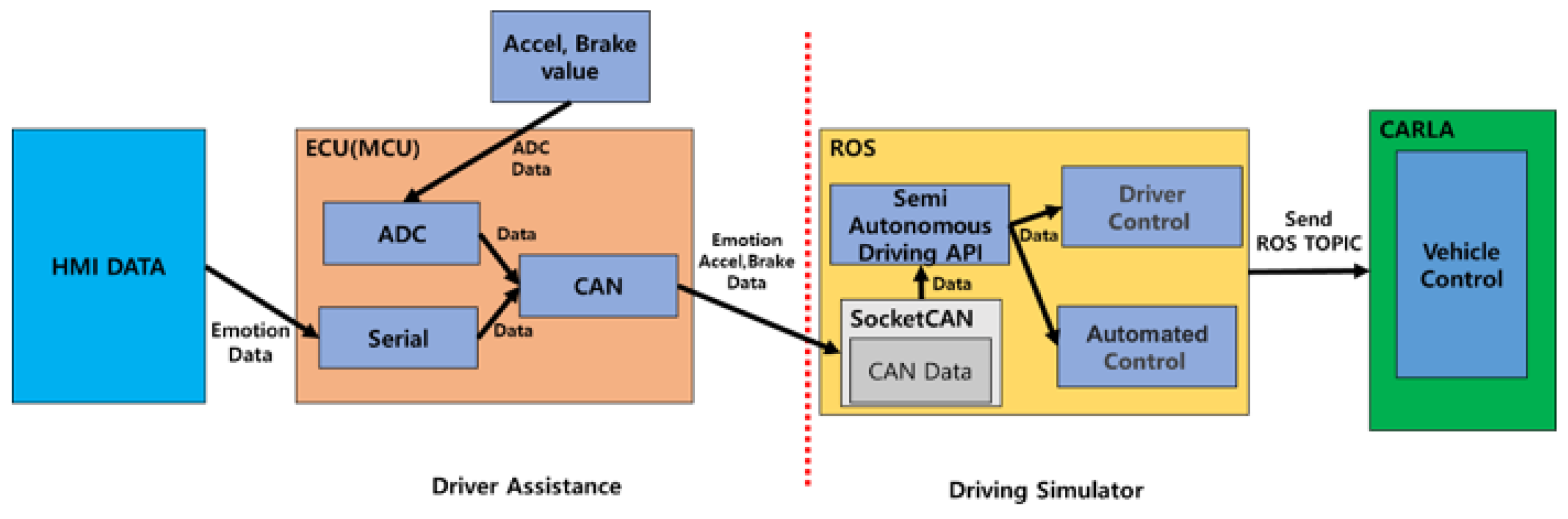
3.1. Semi-Autonomous Driving

The vehicle information and sensor data were managed using the ROS. The ROS bridge was used to link the CARLA simulator and ECU data. The data generated in the CARLA simulator are transmitted through the CARLA ROS bridge, and the received data are processed like various APIs for autonomous driving in each ROS node. Semi-autonomous driving is executed using the ROS message transmitted to the modules of the CARLA simulator. Figure 2 shows the control process of manual and autonomous driving, generated by the ROS rqt graph. Controlling client objects on the CARLA server and verifying the information is managed using ROS CARLA messages. Make_node is a ROS node that controls manual and autonomous driving simultaneously. Vehicle_control_cmd messages are used when controlling a manually driven vehicle, and throttle, brake, and steering values are input as the corresponding message parameters to control the vehicle. Each parameter has a real value ranging from 0 to 100. The throttle and brake values are received from the physical accelerator and brake, and they are transferred to Make_node via the ECU. The akermann_cmd is used as a control message, and the throttle, brake, and steering values are used in vehicle_control_cmd in the carla_akemann_control_ego_vehicle ROS node, which are controlled by Proportional Integral Differential (PID) by setting values (steering angle, steering anglevelocity, speed, acceleration, and jerk). The processed value is then transmitted to the virtual vehicle on the CARLA simulator as a ROS message.

3.2. Driver Assistance Systems

Driver assistance systems were configured based on HILS [38]. The ECU is responsible for controlling the virtual engine and vehicle and receives the HMI result data. The HMI result data are converted to messages via the CAN network. Figure 3 shows a control flowchart for semi-autonomous driving. The parameters of the message include the HMI result data, accelerators, and brake values. In manual operation, the driver receives the accelerator and brake values as ADC data through a controller composed of hardware used for control. This data controls the throttle and brake values of the virtual vehicle. In the control flowchart, autonomous driving is performed for scenarios 1, 2, and 3 based on the driver’s driving ability. Situation 4 was executed by driver control with manual driving ability.
As shown in Figure 4, CAN and serial interfaces were used for communication between the vehicle control hardware. A frame consisting of 3 bytes was used for serial communication between the HMI and ECU. The first index was the 0xFF value as the synchronization signal, the second index was the HMI result data, and the third index was the data end value, using line feed (LF). A total of 3 bytes of the CAN data frame were used for the controller area network between the ECU and driving simulator. Each byte contained different information: the first index data had HMI result data, and the second and third index data were the throttle and brake values, respectively.
To implement the driver assistance system, the environment is configured as shown in Figure 5. The ECU received the result data processed by the HMI through serial communication and received the accelerator and brake values measured by the potentiometer from the controller to the analog-to-digital converter (ADC). The data were converted to a CAN frame and then transmitted to the driving simulator. It was then received through a socket CAN for data reception in the driving simulator. The vehicle configured in CARLA was controlled by determining driver control and autonomous control through the semi-autonomous driving API, which is the ros node.

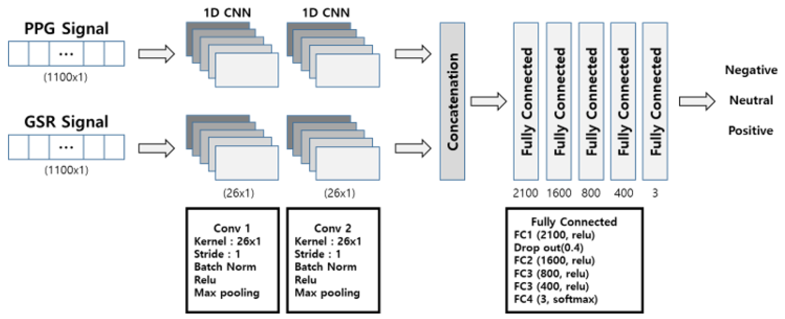
3.3. Human–Machine Interface Using Emotion Recogntion

This study designed a system that recognizes the driver’s situation when switching between manual and autonomous driving and prevents traffic rule violations and accidents. As mentioned above, the driver’s driving ability is influenced by their emotional state. In addition, the driver’s emotions are correlated with the surrounding situation, and they lack the ability to calm themselves when they feel frustrated or angry [39,40]. Inner emotions are represented as a two-dimensional arousal and valence domain [41] to control the vehicle based on the driver’s situation, as shown in Figure 6.
Figure 6a shows the case of decreasing the driver’s speed recognition ability to prevent vehicle traffic accidents caused by excessive acceleration. When the driver is in a state of excessive happiness while driving, it can negatively affect their driving ability, and the subject may drive at a higher speed without focusing on the speedometer and speed control [42]. For an accurate comparison, Pêcher et al. [43] performed experiments on driving while listening to upbeat and soothing music. The results of measuring the vehicle’s average speed and traction control system (TCL) confirmed that driving while listening to happy and exciting music resulted in driver distraction and weakened concentration.
Figure 6b shows the case of decreasing the driver’s cognition and coping ability when an unexpected situation occurs while driving. The emotions of anger that occur in the vehicle’s external environment (traffic jams, quarrels with other drivers, etc.) can confirm that the driver’s aggression, dangerous behavior, and the time it takes to crash increases [44]. Underwood et al. [31] investigated whether causes and factors related to anger while driving could affect the driver’s behavior, and as a result of the experiment, driver’s emotions (anger) related to social deviance and driving violation behavior and specific connectivity were configured.
Figure 6c represents the case of decreasing the driver’s situational judgment or recognition ability of the vehicle situation or driving negligence while driving. The problem of fatigue and drowsiness while driving a vehicle has been a major research area, and various investigations and experiments have been conducted [45]. Brown et al. [46] analyzed driver drowsiness based on EEG signals for drowsiness that occurs while driving. Dong et al. [47] derived the effect on the driver’s condition and driving performance through real-time monitoring and classified the driving carelessness category into distraction and boredom based on the analysis of drowsiness, including bio-signals and physical signals.
Figure 6d represents the case of maintaining driving ability in a normal state, where the driver is not affected by any emotions. It is normally converted to manual driving, and the driver changes the throttle value that directly controls the accelerator to drive the vehicle. When the control method is switched, the driver’s situation can be normally reflected in the vehicle control, enabling stable driving.
When the control is switched to manual driving, the driver’s situation should be reflected in the vehicle control to enable stable driving. However, autonomic nervous system signals that humans cannot control have a few characteristic changes due to emotional changes, and several non-regular signals also exist. Therefore, existing studies have conducted emotion recognition by extracting features from raw bio-signals. Mantini et al. extracted bio-signal features using power spectrum density (PSD) [48], and Topic et al. used topography [49]. However, it is difficult to apply real-time emotion recognition because of the time delay required in the feature extraction process [50,51]. We used PPG [52] and GSR [53] bio-signals with specific regularity, which are easy to acquire in real time. The PPG signal is acquired by attaching an optical sensor to the driver’s index finger. The extracted signal has a regular shape like ECG and includes various information such as blood pressure, volume change, and heart activity. The GSR signal is acquired by measuring the skin conductance on the middle and ring fingers. It includes information on the amount of change such as sweat secretion and body temperature according to the driver’s body and emotions. In addition, we did not use the aforementioned feature extraction method through handcrafts. However, raw data are difficult to use immediately as training data and data for real-time emotion recognition, and a Butterworth filter is applied to remove low-frequency components of the data. High-order polynomial and moving average filters were used to reduce the baseline fluctuations and dynamic noise. After dividing the preprocessed bio-signals into short lengths of 1.1 s waveform units, data characteristics and learning were performed using a 1D CNN model.
An artificial neural network (ANN) consists of three layers: input, hidden, and output. However, it is difficult for the existing ANN to find the optimal value of the parameter, and it is often vulnerable to distortion due to movement and change [54]. The convolutional neural network (CNN), an improved model, is based on the weights and biases of the previous layer in the same way as an ANN, but it consists of a structure that extracts data features and understands rules. Therefore, in a recent study, a method of extracting and classifying signal features using a 1D CNN model for various voices and bio-signals was applied [55]. The configuration diagram of the multimodal 1D CNN used in this study is shown in Figure 7.

4. Experiment Results

4.1. Experimental Environment

As shown in Table 1, the PPG and GSR signals of session1 of the MERTI-Apps [56] dataset were used as learning data. The data used in session 1 were measured by attaching electrodes to the index finger for the PPG signal and the middle and ring fingers for the GSR signal at 1 kHz using BIOPACK’s MP150 equipment. The first 5 s and the last 5 s were excluded to remove noise from the signal. A total of 32,000 segments, defined by 1100 samples, were extracted from the extracted waveform unit signal data. The range of labeling of the bio-signal data was −100–100. Table 2 shows the overall experimental environment, which includes a driving simulator PC configuring a virtual environment, vehicles, and ECU for communicating with HMI-PC and driving-simulator-PC, and an HMI PC for deriving 1D CNN model-based results after processing data received from bio-signal sensors. The Shimmer data acquisition device and HMI PC were connected to collect bio-signal data to recognize the driver’s emotions. The STM3204G-EVAL board, an microcontroller unit(MCU) board, was used to configure the ECU mounted on the driving simulator vehicle. The ECU uses the CAN protocol to transmit and receive data between the HMI PC and ego vehicles in a driving simulator. The overall Configurations are shown in Figure 8.
The experiment was conducted on the Town1 map provided by the CARLA simulator. Figure 9a is a picture of the Town1 map, and the part marked in blue represents the waypoints and routes the vehicle will track. The vehicle was driven on the road with a speed limit of 40 km/h, and the starting point was point A. After driving around the map once, the same point, A, was the destination. Figure 9b is a screenshot for vehicle monitoring made by Rviz of ROS, which is used to monitor camera and sensor data of the vehicle in real time. In evaluating driving ability according to a driver’s situation, situational awareness occurs on a straight lane section on the route. We classified four scenarios according to the bio-signal data seized from the driver’s hands. The first scenario was to recognize the decrease in the driver’s driving ability for speed perception. When an event occured, the vehicle driving at 40 km/h was forcibly speed-limited to 20 km/h. The second scenario was to recognize the decrease in incident reaction ability, and when an incident occured, the vehicle that was driving at 40 km/h was suddenly stopped at 0 km/h. The incident was terminated when a bio-input signal other than the existing bio-input signal was received. The third scenario was to recognize the decrease in the ability to judge the driving situation. In the driving scenario, the vehicle was driving at 40 km/h, and when an event occured, the vehicle drove at 20 km/h, and after a certain period of time, the vehicle completely stopped at 0 km/h. The fourth scenario was to maintain driving capability. When an event occured, the driver’s manual control was switched to directly control the accelerator, and the throttle value changed to drive the vehicle freely. Table 3 shows the accuracy and data size according to the scenarios.

4.2. Experimental Result

When the virtual vehicle received CAN data sent from the ECU, we measured the response time to take control of the vehicle in the event of a disengagement. For timing measurement, the response time was measured from the time taken for the driving simulator PC to control the vehicle by receiving the data in CAN format by converting the result data processed on the HMI PC into CAN data on the ECU board. In the experiment, four scenarios were performed, and the response times of start control and end control for each scenario were measured, respectively. For more accurate results, these experiments were repeated 10 times. Table 4 lists the average and total response times of the controls in the driver assistance system when the experiment of the four scenarios was repeated ten times. The average vehicle control response time was 351.75 ms, and the standard deviation was 12.13 ms, half of the aforementioned standard control time of 830 ms, showing a fast time. Also, as shown in Table 5, the data processing time for emotion recognition has a total average time of 66.1ms and a standard deviation of 4.1ms. Even if the vehicle control system and the emotion recognition module are used together, it was confirmed that total reaction time (417.85 ms) is within the stable scope of the commercial reaction time standard. To check the target speed of the vehicle in progress for each given scenario, Figure 10 shows vehicle (speed, throttle, brake) data values and control status values for each scenario. Figure 10a shows the target speed according to the total scenario, and Figure 10b–e show measured vehicle speed, throttle, and brake values for each scenario performed in the experiment. We can see that the throttle and braking data values work correctly depending on the vehicle speed appropriate for the scenario. When verifying the experimental results, it ensures that the results are similar to the target scenario and that the overall response time is within the standard scope. The experimental results confirmed the possibility of real-time vehicle control through the driver’s situational awareness.

5. Discussion

Using the results of the multimodal bio-signal-based 1D CNN model, a study on the driving assistance control module when the driver drives the vehicle was conducted on the simulator. Autonomous driving can also be used to develop an autonomous driving system through human emotions, and the interaction between the driver and the vehicle is necessary when manually controlling the vehicle and changing the mode.
When comparing previous studies based on our research results, Meshram et al. [36] proposed an architecture of semi-autonomous driving system combining with emotion recognition through human faces and only collected and classified data for the driver’s four emotions. In contrast, we designed and implemented eight emotion based driving assistance systems using PPG and GSR signals and derived the experimental results in terms of response time. Izquierdo-Reyes et al. [4] in the study of the driver assistance system configuration presented the driver’s emotion recognition using the EEG signal whereas they did not implement vehicle control method combined with emotion recognition. However, we have built a semi-autonomous driving system that connects HMI that recognizes the driver’s emotions and driving simulator through ECU and CAN networks.
In the study of Dixit et al. [57], the average reaction time for controlling the vehicle was 0.83 s, which corresponds to the distribution of stable reaction time required by automobile vendors. Our experimental results showed stable vehicle controllability coping with situational awareness based on emotional recognition at 417.85 ms. In previous studies, 830 ms is required for the time required to control the vehicle when an event occurs. Therefore, the vehicle control response time for changing the driving mode was measured in the scenario, and it was confirmed that the response times for the start control and end control for each scenario event could be used in autonomous driving system. In addition, it is confirmed that there is no problem with adding various autonomous driving modules. It is possible to apply to actual vehicles as hardware and software semi-autonomous driving modules with maintainability and availability using HILS and driving simulator.
Unlike robots, human emotions do not change rapidly. Therefore, the stored bio-signal data were used for accurate vehicle control in the simulator. If the system is studied for each situation using various autonomous driving sensors in the future, development and research will proceed in various driving assistance systems and autonomous driving systems. This study confirmed that the convergence of various fields and autonomous driving research is possible by approaching the proposed new module equipped with the driver’s situation and emotion recognition as a center of interaction between passengers and vehicles rather than a vehicle-centered existing autonomous driving system module.

6. Conclusions

This study confirmed the possibility of a module for vehicle driving speed control based on multimodal bio-signals. To analyze the driver’s emotions, we proposed a vehicle speed control and driving assistance system module using a 1D CNN model without input data of 1.1 s and without separate feature extraction to analyze the driver’s emotions. The virtual city and vehicle environment were configured in the CARLA simulator server to configure an environment similar to a real vehicle. The ECU board was used to configure the same communication system as a real vehicle. In addition, CAN communication, which is widely used for in-vehicle communication, and situation scenario, and accelerator data were transmitted to the virtual environment vehicle, and the data managed by ROS middleware was monitored in real time to compare the measured and target values. The proposed prototype system shows stable performance of the average reaction speed of 351.75 ms, the standard deviation of 12.13 ms, the average processing time of 66.1 ms, and the total processing time of 417.85 ms. As can be seen from the experimental results, it can be confirmed that the proposed driver assistance system accurately achieves the target speed and vehicle control for each situation. In future research, we plan to study autonomous driving by integrating various autonomous driving sensors and systems such as automotive ethernet, bio-signals, and object recognition, which are advanced vehicle core technologies.

Author Contributions

Conceptualization, H.-G.L. and D.-H.K. (Dong-Hyun Kang); methodology, H.-G.L. and D.-H.K. (Dong-Hyun Kang); software, H.-G.L.; validation, D.-H.K. (Dong-Hyun Kang) and D.-H.K. (Deok-Hwan Kim); formal analysis, D.-H.K. (Deok-Hwan Kim); investigation, H.-G.L. and D.-H.K. (Dong-Hyun Kang); resources, D.-H.K. (Deok-Hwan Kim); data curation, D.-H.K. (Dong-Hyun Kang); writing—original draft preparation, H.-G.L.; writing—review and editing, D.-H.K. (Deok-Hwan Kim); visualization, H.-G.L. and D.-H.K. (Deok-Hwan Kim); supervision, D.-H.K. (Deok-Hwan Kim); project administration, D.-H.K. (Deok-Hwan Kim); funding acquisition, D.-H.K. (Deok-Hwan Kim), All authors have read and agreed to the published version of the manuscript.

Funding

This work was supported by the Institute for Information & Communications Technology Promotion (IITP) grant funded by the Korean government (MSIT) (No.2019-0-00064, Intelligent Mobile Edge Cloud Solution for Connected Car), and in part by the Industrial Technology Innovation Program funded by the Ministry of Trade, Industry and Energy (MI, Korea) [10073154, Development of human-friendly human–robot interaction technologies using human internal emotional states] and in part by a National Research Foundation of Korea(NRF) grant funded by the Korean government(MSIT) (No. NRF-2021R1F1A1050750).

Institutional Review Board Statement

This study was conducted by the IRB standard operating guidelines of the Institutional Review Board of Inha University. It was performed according to the approval number (170403-2AR) and the latest approval date (29 December 2020).

Informed Consent Statement

Informed consent was obtained from all subjects involved in the study.

Conflicts of Interest

The authors declare no conflict of interest.

References

  1. Jeon, M. Chapter 1—Emotions and Affect in Human Factors and Human–Computer Interaction: Taxonomy, Theories, Approaches, and Methods. In Emotions and Affect in Human Factors and Human-Computer Interaction; Jeon, M., Ed.; Academic Press: Cambridge, MA, USA, 2017; pp. 3–26. ISBN 9780128018514. [Google Scholar]
  2. Egerstedt, M.; Hu, X.; Stotsky, A. Control of a car-like robot using a virtual vehicle approach. In Proceedings of the 37th IEEE Conference on Decision and Control (Cat. No.98CH36171), Tampa, FL, USA, 18 December 1998; Volume 2, pp. 1502–1507. [Google Scholar] [CrossRef]
  3. Jeon, M.; Walker, B.N.; Yim, J.-B. Effects of specific emotions on subjective judgment, driving performance, and perceived workload. Transp. Res. Part F Traffic Psychol. Behav. 2014, 24, 197–209. [Google Scholar] [CrossRef]
  4. Javier, I.R.; Ramirez-Mendoza, R.A.; Bustamante-Bello, R.; Pons-Rovira, J.L.; Gonzalez-Vargas, J. Emotion recognition for semi-autonomous vehicles framework. Int. J. Interact. Des. Manuf. 2018, 12, 1447–1454. [Google Scholar]
  5. Grimm, M.; Kroschel, K.; Harris, H.; Nass, C.; Schuller, B.; Rigoll, G.; Moosmayr, T. On the necessity and feasibility of detecting a driver’s emotional state while driving. In International Conference on Affective Computing and Intelligent Interaction; Springer: Berlin/Heidelberg, Germany, 2007. [Google Scholar]
  6. Pereira, J.L.F.; Rossetti, R.J.F. An Integrated Architecture for Autonomous Vehicles Simulation. In Proceedings of the SAC’12: 27th Annual ACM Symposium on Applied Computing, New York, NY, USA, 26–30 March 2012. [Google Scholar]
  7. Deter, D.; Wang, C.; Cook, A.; Perry, N.K. Simulating the Autonomous Future: A Look at Virtual Vehicle Environments and How to Validate Simulation Using Public Data Sets. IEEE Signal Process. Mag. 2021, 38, 111–121. [Google Scholar] [CrossRef]
  8. CARLA Simulator. Available online: https://carla.org./ (accessed on 10 August 2021).
  9. Dosovitskiy, A.; Ros, G.; Codevilla, F.; Lopez, A.; Koltun, V. CARLA: An open urban driving simulator. In Proceedings of the Conference on Robot Learning, Mountain View, CA, USA, 13–15 November 2017; pp. 1–16. [Google Scholar]
  10. Blaga, B.; Nedevschi, S. Semantic Segmentation Learning for Autonomous UAVs using Simulators and Real Data. In Proceedings of the 2019 IEEE 15th International Conference on Intelligent Computer Communication and Processing (ICCP), Cluj-Napoca, Romania, 5–7 September 2019; pp. 303–310. [Google Scholar] [CrossRef]
  11. Zofka, M.R. Pushing ROS towards the Dark Side: A ROS-based Co-Simulation Architecture for Mixed-Reality Test Systems for Autonomous Vehicles. In Proceedings of the 2020 IEEE International Conference on Multisensor Fusion and Integration for Intelligent Systems (MFI), Karlsruhe, Germany, 14–16 September 2020; pp. 204–211. [Google Scholar] [CrossRef]
  12. Hanselmann, H. Hardware-in-the-loop simulation testing and its integration into a CACSD toolset. In Proceedings of the Joint Conference on Control Applications Intelligent Control and Computer Aided Control System Design, Dearborn, MI, USA, 15–18 September 1996; pp. 152–156. [Google Scholar] [CrossRef]
  13. Onuma, Y.; Terashima, Y.; Kiyohara, R. ECU Software Updating in Future Vehicle Networks. In Proceedings of the 2017 31st International Conference on Advanced Information Networking and Applications Workshops (WAINA), Taipei, Taiwan, 27 March 2017; pp. 35–40. [Google Scholar] [CrossRef]
  14. Johansson, K.H.; Törngren, M.; Nielsen, L. Vehicle Applications of Controller Area Network. In Handbook of Networked and Embedded Control Systems; Hristu-Varsakelis, D., Levine, W.S., Eds.; Control Engineering; Birkhäuser Boston: Cambridge, MA, USA, 2005. [Google Scholar] [CrossRef] [Green Version]
  15. CAN Specification; Version 2.0; Robert Bosch GmbH: Stuttgart, Germany, 1991.
  16. Lin, C.-T.; Wu, R.-C.; Jung, T.-P.; Liang, S.-F.; Huang, T.-Y. Estimating Driving Performance Based on EEG Spectrum Analysis. EURASIP J. Adv. Signal Process. 2005, 19, 1–10. [Google Scholar] [CrossRef] [Green Version]
  17. Schier, M.A. Changes in EEG alpha power during simulated driving: A demonstration. Int. J. Psychophysiol. 2000, 37, 155–162. [Google Scholar] [CrossRef]
  18. Giannakakis, G.; Grigoriadis, D.; Giannakaki, K.; Simantiraki, O. Review on psychological stress detection using bio-signals. IEEE Trans. Affect. Comput. 2019. [Google Scholar] [CrossRef]
  19. Sini, J.; Marceddu, A.C.; Violante, M. Automatic emotion recognition for the calibration of autonomous driving functions. Electronics 2020, 9, 518. [Google Scholar] [CrossRef] [Green Version]
  20. Kamaruddin, N.; Wahab, A. Driver behavior analysis through speech emotion understanding. In Proceedings of the 2010 IEEE Intelligent vehicles symposium, San Diego, CA, USA, 21–24 June 2010. [Google Scholar]
  21. Sheng, W.; Ou, Y.; Tran, D.; Tadesse, E.; Liu, M. An integrated manual and autonomous driving framework based on driver drowsiness detection. In Proceedings of the 2013 IEEE/RSJ International Conference on Intelligent Robots and Systems, Tokyo, Japan, 3–7 November 2013. [Google Scholar]
  22. Sini, J.; Marceddu, A.; Violante, M.; Dessì, R. Passengers’ Emotions Recognition to Improve Social Acceptance of Autonomous Driving Vehicles. In Progresses in Artificial Intelligence and Neural Systems; Springer: Singapore, 2021; pp. 25–32. [Google Scholar]
  23. Marceddu, A.C. Automatic Recognition And Classification Of Passengers’ Emotions In Autonomous Driving Vehicles. Master’s Thesis, Diss. Politecnico di Torino, Torino, Italy, 2019. [Google Scholar]
  24. Du, N.; Zhou, F.; Pulver, E.M.; Tilbury, D.M.; Robert, L.P.; Pradhan, A.K.; Yang, X.J. Examining the effects of emotional valence and arousal on takeover performance in conditionally automated driving. Transp. Res. Part C Emerg. Technol. 2020, 112, 78–87. [Google Scholar] [CrossRef]
  25. Steinhauser, K.; Leist, F.; Maier, K.; Michel, V.; Pärsch, N.; Rigley, P.; Wurm, F.; Steinhauser, M. Effects of emotions on driving behavior. Transp. Res. Part F Traffic Psychol. Behav. 2018, 59, 150–163. [Google Scholar] [CrossRef]
  26. Abdu, R.; Shinar, D.; Meiran, N. Situational (state) anger and driving. Transp. Res. Part F Traffic Psychol. Behav. 2012, 15, 575–580. [Google Scholar] [CrossRef]
  27. Hancock, G.M.; Hancock, P.A.; Janelle, C.M. The Impact of Emotions and Predominant Emotion Regulation Technique on Driving Performance. Work 2012, 41, 3608–3611. [Google Scholar] [CrossRef] [Green Version]
  28. Ünal, A.B.; de Waard, D.; Epstude, K.; Steg, L. Driving with music: Effects on arousal and performance. Transp. Res. Part F Traffic Psychol. Behav. 2013, 21, 52–65. [Google Scholar] [CrossRef]
  29. Tefft, B.C.; Arnold, L.S.; Grabowski, J.G. AAA Foundation for Traffic Safety; AAA Foundation for Traffic Safety: Washington, DC, USA, 2016. [Google Scholar]
  30. Dingus, T.A.; Guo, F.; Lee, S.; Antin, J.F.; Perez, M.; Buchanan-King, M.; Hankey, J. Driver crash risk factors and prevalence evaluation using naturalistic driving data. Proc. Natl. Acad. Sci. USA 2016, 113, 2636–2641. [Google Scholar] [CrossRef] [Green Version]
  31. Underwood, G.; Chapman, P.; Wright, S.; Crundall, D. Anger while driving. Transp. Res. Part F Traffic Psychol. Behav. 1999, 2, 55–68. [Google Scholar] [CrossRef]
  32. Hu, H.; Zhu, Z.; Gao, Z.; Zheng, R. Analysis on Bio-signal Characteristics to Evaluate Road Rage of Younger Drivers: A Driving Simulator Study. In Proceedings of the 2018 IEEE Intelligent Vehicles Symposium (IV), Suzhou, China, 17 December 2018; pp. 156–161. [Google Scholar] [CrossRef]
  33. McKenna, F.P. The human factor in driving accidents An overview of approaches and problems. Ergonomics 1982, 25, 867–877. [Google Scholar] [CrossRef]
  34. Jenke, R.; Peer, A.; Buss, M. Feature extraction and selection for emotion recognition from EEG. IEEE Trans. Affect. Comput. 2014, 5, 327–339. [Google Scholar] [CrossRef]
  35. Pritam, S.; Etemad, A. Self-supervised ECG representation learning for emotion recognition. IEEE Trans. Affect. Comput. 2020. [Google Scholar] [CrossRef]
  36. Meshram, H.A.; Sonkusare, M.G.; Acharya, P.; Prakash, S. Facial Emotional Expression Regulation to Control the Semi-Autonomous Vehicle Driving. In Proceedings of the 2020 IEEE International Conference for Innovation in Technology (INOCON), Bangalore, India, 6–8 November 2020. [Google Scholar]
  37. Hussein, A.; García, F.; Olaverri-Monreal, C. ROS and Unity Based Framework for Intelligent Vehicles Control and Simulation. In Proceedings of the 2018 IEEE International Conference on Vehicular Electronics and Safety (ICVES), Madrid, Spain, 12–14 September 2018; pp. 1–6. [Google Scholar] [CrossRef]
  38. Jin, W.; Baracos, P. A Scalable Hardware-in-the-Loop System for Virtual Engine and Virtual Vehicle Applications No. 2003-01-1367. SAE Tech. Pap. 2003. [Google Scholar] [CrossRef]
  39. James, L. Road Rage and Aggressive Driving: Steering Clear of Highway Warfare; Prometheus Books: Amherst, NY, USA, 2009. [Google Scholar]
  40. Völkel, S.T.; Graefe, J.; Schödel, R.; Häuslschmid, R.; Stachl, C.; Au, Q. I Drive My Car and My States Drive Me: Visualizing Driver’s Emotional and Physical States. In Proceedings of the 10th International Conference on Automotive User Interfaces and Interactive Vehicular Applications, Toronto, ON, Canada, 23–25 September 2018. [Google Scholar]
  41. Russell, J.A.; Weiss, A.; Mendelsohn, A.G. Affect grid: A single-item scale of pleasure and arousal. J. Personal. Soc. Psychol. 1989, 57, 493. [Google Scholar] [CrossRef]
  42. Angel, R.M.; Nunes, L. Mental load and loss of control over speed in real driving. Towards a theory of attentional speed control. Transp. Res. Part F Traffic Psychol. Behav. 2002, 5, 111–122. [Google Scholar]
  43. Christelle, P.; Lemercier, C.; Cellier, J.-M. Emotions drive attention: Effects on driver’s behaviour. Saf. Sci. 2009, 47, 1254–1259. [Google Scholar]
  44. Deffenbacher, J.L.; Deffenbacher, D.M.; Lynch, R.S.; Richards, T.L. Anger, aggression, and risky behavior: A comparison of high and low anger drivers. Behav. Res. Ther. 2003, 41, 701–718. [Google Scholar] [CrossRef]
  45. Vanlaar, W.; Simpson, H.; Mayhew, D. Fatigued and drowsy driving: A survey of attitudes, opinions and behaviors. J. Saf. Res. 2008, 39, 303–309. [Google Scholar] [CrossRef]
  46. Brown, T.; Johnson, R.; Milavetz, G. Identifying periods of drowsy driving using EEG. Ann. Adv. Automot. Med. 2013, 57, 99. [Google Scholar]
  47. Dong, Y.; Hu, Z.; Uchimura, K.; Murayama, N. Driver inattention monitoring system for intelligent vehicles: A review. IEEE Trans. Intell. Transp. Syst. 2010, 12, 596–614. [Google Scholar] [CrossRef]
  48. Mantini, D.; Perrucci, M.G.; Del Gratta, C.; Romani, G.L.; Corbetta, M. Electrophysiological signatures of resting state networks in the human brain. Proc. Natl. Acad. Sci. USA 2007, 104, 13170–13175. [Google Scholar] [CrossRef] [Green Version]
  49. Topic, A.; Russo, M. Emotion recognition based on EEG feature maps through deep learning network. Eng. Sci. Technol. Int. J. 2021. [Google Scholar] [CrossRef]
  50. Samara, A.; Menezes, M.L.R.; Galway, L. Feature Extraction for Emotion Recognition and Modelling Using Neurophysiological Data. In Proceedings of the 2016 15th International Conference on Ubiquitous Computing and Communications and 2016 International Symposium on Cyberspace and Security (IUCC-CSS), Granada, Spain, 14–16 December 2016; pp. 138–144. [Google Scholar]
  51. Supratak, A.; Wu, C.; Dong, H.; Sun, K.; Guo, Y. Survey on feature extraction and applications of bio-signals. In Machine Learning for Health Informatics. Springer: Cham, Switzerland, 2016; pp. 161–182. [Google Scholar] [CrossRef] [Green Version]
  52. Alian, A.A.; Kirk, H.S. Photoplethysmography. Best Pract. Res. Clin. Anaesthesiol. 2014, 28, 395–406. [Google Scholar] [CrossRef]
  53. Jacobs, K.W.; Frank, E.H., Jr. Effects of four psychological primary colors on GSR, heart rate and respiration rate. Percept. Mot. Ski. 1974, 38, 763–766. [Google Scholar] [CrossRef]
  54. Fukushima, K.; Miyake, S. Neocognitron: A Self-Organizing Neural Network Model for a Mechanism of Visual Pattern Recognition. In Lecture Notes in Biomathematics; Springer: Berlin/Heidelberg, Germany, 1982; pp. 267–285. [Google Scholar] [CrossRef]
  55. Lin, Y.-Y.; Zheng, W.-Z.; Chu, W.; Han, J.-Y.; Hung, Y.-H.; Ho, G.-M.; Chang, C.-Y.; Lai, Y.-H. A Speech Command Control-Based Recognition System for Dysarthric Patients Based on Deep Learning Technology. Appl. Sci. 2021, 11, 2477. [Google Scholar] [CrossRef]
  56. Maeng, J.-H.; Kang, D.-H.; Kim, D.-H. Deep Learning Method for Selecting Effective Models and Feature Groups in Emotion Recognition Using an Asian Multimodal Database. Electronics 2020, 9, 1988. [Google Scholar] [CrossRef]
  57. Dixit, V.V.; Chand, S.; Nair, D.J. Autonomous Vehicles: Disengagements, Accidents and Reaction Times. PLoS ONE 2016, 11, e0168054. [Google Scholar] [CrossRef] [PubMed] [Green Version]
Figure 1. Architecture of driver-assistance system that recognizes the driver’s situation and emotions based on bio-signals.
Electronics 10 02405 g001
Figure 2. Rqt-graph of vehicle control for semi-autonomous driving.
Electronics 10 02405 g002
Figure 3. Semi-autonomous driving control flowchart.
Electronics 10 02405 g003
Figure 4. Communication frame for driver assistance systems.
Electronics 10 02405 g004
Figure 5. Driver assistance systems.
Electronics 10 02405 g005
Figure 6. Two-dimensional arousal and valence domains by situation; (a) Speed perception ability; (b) Sudden situation recognition ability; (c) Driving situation judgment ability; (d) The ability to drive.
Electronics 10 02405 g006
Figure 7. Proposed 1D CNN model for driver’s situation and emotion recognition.
Electronics 10 02405 g007
Figure 8. Experimental sequence schematic for semi-autonomous driving.
Electronics 10 02405 g008
Figure 9. Experimental maps and data monitoring; (a) Route planning and simulator maps; (b) Rviz screen for vehicle monitoring.
Electronics 10 02405 g009
Figure 10. Semi-autonomous driving result graph; (a) target speed according to scenario; (be) vehicle speed, throttle, and brake value graphs in each scenario.
Electronics 10 02405 g010
Table 1. Bio-signal data summary used in session 1 in the MERTI-Apps dataset.
Participants and Modalities
ParticipantsTotal 62 (males: 28 and females: 34)
Recorded signalsPPG (1 kHz), GSR (1 kHz)
Self-reportArousal, valence
Session 15 videos (sad: 1, happy: 1, angry: 2, scared: 1)
PPG, GSR signals
Table 2. Experimental environment.
DeviceHardwareSoftware
Simulator PCCPU-Intel® Core™ i5-7500 GPU-GeForce GTX 1080 8G RAM 32 GB
OS-Ubuntu 20.04.2 LTS
CARLA Simulator-0.9.10
ROS-Noetic
HMI PCCPU-Intel® Core™ i7-9700 GPU-GeForce GTX 2080TI 12G RAM 64 GB
OS-Window 10
Python 3.6.0
Tensorflow 2.4.0
ECU(MCU)Borad- STM3240G-EVAL
CORE- ARM® Cortex®-M4
Chip- STM32F407IGH6
Table 3. Data composition and accuracy for each scenario used in the experiment.
(a) Scenario 1 (Speed perception ability) Data(b) Scenario 2 (incident reaction ability) Data
Targetjoy, happinessTargetangry, upset
Arousal33–100Arousal33–100
Valence−33–100Valence−100–33
Total segments5400 segments in
1 pulse unit
Total segments5400 segments in
1 pulse unit
Average
accuracy
Arousal75%Average
accuracy
Arousal70%
Valence72%Valence82%
(c) Scenario 3 (Driving situation judgment ability) Data(d) Scenario 4 (the ability to drive normally) Data
Targettiredness, boredomTargetneutral feelings
Arousal−100–33Arousal−33–33
Valence−100–33Valence−33–33
Total segments5400 segments in
1 pulse unit
Total segments5400 segments in
1 pulse unit
Average
accuracy
Arousal70%Average
accuracy
Arousal85%
Valence84%Valence70%
Table 4. Response time of control in driver assistance system.
12345678910Avg
Scenario 1319 ms342 ms291 ms321 ms387 ms345 ms340 ms384 ms389 ms307 ms342.5 ms
332 ms356 ms315 ms280 ms323 ms334 ms319 ms358 ms348 ms326 ms329.1 ms
Scenario 2352 ms376 ms354 ms410 ms307 ms362 ms329 ms338 ms368 ms383 ms357.9 ms
326 ms375 ms389 ms360 ms340 ms376 ms394 ms386 ms389 ms305 ms364 ms
Scenario 3359 ms334 ms364 ms298 ms360 ms375 ms368 ms312 ms360 ms355 ms348.5 ms
387 ms307 ms370 ms319 ms332 ms354 ms385 ms358 ms323 ms303 ms343.8 ms
Scenario 4398 ms389 ms362 ms378 ms308 ms356 ms381 ms343 ms396 ms355 ms366.6 ms
376 ms379 ms337 ms344 ms378 ms356 ms343 ms364 ms394 ms345 ms361.6 ms
Table 5. Time to derive emotional results based on bio-signals.
12345678910Avg
Scenario 162.7 ms68.1 ms60.7 ms72.4 ms63.4 ms68.4 ms62.1 ms61.8 ms64.8 ms71.8 ms65.62 ms
Scenario 264.6 ms66.4 ms64.6 ms73.1 ms65.6 ms73.5 ms68.4 ms66.1 ms60.1 ms70.3 ms67.27 ms
Scenario 367.1 ms65.8 ms61.2 ms68.5 ms64.7 ms61.3 ms74.2 ms65.4 ms60.9 ms73.1 ms66.22 ms
Scenario 463.5 ms67.1 ms70.2 ms64.3 ms64.9 ms61.2 ms68.9 ms60.3 ms60.8 ms72.7 ms65.39 ms
Publisher’s Note: MDPI stays neutral with regard to jurisdictional claims in published maps and institutional affiliations.

