Article

A United Control Strategy of Photovoltaic-Battery Energy Storage System Based on Voltage-Frequency Controlled VSG

Key Laboratory of Distributed Energy Storage and Micro-Grid in Hebei, North China Electric Power University, Baoding 071003, China
*
Author to whom correspondence should be addressed.
Electronics 2021, 10(17), 2047; https://doi.org/10.3390/electronics10172047
Submission received: 13 July 2021 / Revised: 11 August 2021 / Accepted: 19 August 2021 / Published: 24 August 2021

Abstract

:
At present, the installed capacity of photovoltaic-battery energy storage systems (PV-BESs) is rapidly increasing. In the traditional control method, the PV-BES needs to switch the control mode between off-grid and grid-connected states. Thus, the traditional control mode reduces the reliability of the system. In addition, if the system is accidentally disconnected from the grid or the energy storage battery fails to work normally, the DC voltage of the inverter increases or decreases rapidly. To address these two problems, in this paper, a united control strategy is proposed. In the case of grid connection, based on the voltage-frequency controlled VSG strategy, the strategy adjusts the output power of the VSG by changing the position of the primary frequency modulation curve. This method can ensure that, after the system is connected to the grid, excess PV power can be sent to the grid, or power can be absorbed from the grid to charge energy storage. In the off-grid state, the strategy uses FPPT technology and superimposes a voltage component onto the voltage loop to quickly balance the DC power and AC power of the inverter. This strategy can improve the reliability of the system’s power supply if the energy storage fails to work normally. Finally, a PV-BES model was built using MATLAB-Simulink, and the simulation results proved the effectiveness of the proposed strategy.

1. Introduction

As a form of renewable energy, photovoltaic (PV) power is developing rapidly. In 2019, the global newly installed PV capacity was 115 GW, and the total installed PV capacity reached 627 GW [1]. For the full year, solar PV accounted for around 10.7% of total generation in Honduras and substantial shares also in Italy (8.6%), Greece (8.3%), Germany (8.2%), Chile (8.1%), Australia (7.8%), and Japan (7.4%), among others. Enough capacity was in operation worldwide by year’s end to produce around 2.8% of global electricity generation and 24.6% of new energy electricity generation [1]. PV has the two characteristics of volatility and randomness, which determine the output characteristics of PVPP. The uncertainty of PV power makes it difficult to ensure the reliability of load power supply when it is off-grid [2,3,4,5]. Therefore, a PV power plant (PVPP) is often used in conjunction with an energy storage system (ESS) in practice, which together are called a photovoltaic-battery energy storage system (PV-BES) [3,4,6,7]. Although the system can work completely off-grid in most cases, the system requires a connection to the grid, either to send the power generated by PV into the grid, or to absorb energy from the grid to charge the energy storage battery. According to whether it is connected to the power grid, the operating state of the system can be divided into two operating modes: (1) off-grid operation mode and (2) grid-connected operation mode [5,8]. At present, the strategy for connecting PV to the grid requires the capability of switching modes to achieve the functions of off-grid or grid-connected. When the PVPP is off-grid, it works in voltage source mode [8], and switches to the current source control mode when the PVPP is connected to the grid. The advantage of this method is that the control structure is simple. Following connection to the grid, the inner loop controls the inductor’s current and the outer loop controls the DC voltage, and can thus send all of the PV power into the grid [8,9]. However, the disadvantage of this method is that the control strategy needs to change to switch the control mode between off-grid and grid-connected. Although strategies proposed in previous papers aim to make the process of mode switching as smooth as possible, the power supply of the load is not affected during the switching period [7,9,10,11,12]. However, when the system encounters unexpected off-grid situations, such as grid failure, the local load experiences short-term power failure [8].
Because clean energy still needs to be connected to the synchronous power grid for a long period, virtual synchronous generator (VSG) technology has emerged [13,14]. VSG technology controls the inverter according to the swing equation, providing the inverter with the characteristics of a partial synchronous generator [13,14]. Thus, the VSG strategy technology can suppress frequency and power fluctuations in the microgrid. At present, there are two control methods for renewable energy-based microgrids. One is to use microgrid central controllers (MGCCs) to control distributed generation (DG). In [15], a hierarchical control structure was proposed for a renewable energy-based microgrid, which can regulate the operation of an islanded AC microgrid experiencing communication link failures. The MGCC can realize precise control of each DG. However, this method is subject to the communication problem of each inverter and the high cost is not conducive to large-scale application [16]. The other control method is VSG technology. VSG can be applied in microgrids without a central controller, and each VSG runs independently [17]. The DG controlled by a VSG has the same operating mechanism as the synchronous generator, and can independently participate in the operation and management of the power grid [16,17,18]. In addition, if the power grid is abnormal or faulty, the VSG can provide inertia and damping for the power grid [19,20,21,22,23]. The voltage-frequency controlled VSG has the droop characteristics of active power-frequency and reactive power-voltage, which is convenient for multi-generator parallel connection and the connection to the grid [16,17,22,23]. At present, numerous scholars have discussed and improved the VSG technology [16,17,18,19,20,21,22,23]. Initially, no damping unit was added to the VSG strategy [13,14]. Subsequently, studies have added a damping unit to the VSG through different methods to provide effective damping [19,20]. Moreover, research has proposed different adaptive virtual impedance control strategies to address the problem of VSG grid connection [16,17]. An adaptive strategy was proposed to improve the steady-state droop to suppress the frequency and power oscillations of the VSG [21]. VSG technology has been used to enable new energy to participate in grid frequency regulation, and to optimize the droop parameters of VSG [22]. Previous research has also provided a calculation method for the droop coefficient and virtual impedance [23]. In addition, an important advantage of VSG technology is that it can make the inverter run in multi-operating modes, such as grid-connected mode, islanded single-distributed generator (ISDG) mode, and islanded multi-distributed generator (IMDG) mode [24,25]. VSG technology can ensure that the inverter is a voltage source in different operating modes, and can avoid switching between different control modes [24,25,26,27].
It is a challenge for the existing VSG strategy to meet the needs of PV-BES multiple working modes. To address this issue, in this study, a secondary frequency adjustment method was added to the voltage-frequency controlled VSG to meet the needs of PV-BES grid-connected working mode. Moreover, a new off-grid control strategy for PV-BES was proposed, which can solve the problem of abnormal DC voltage when the energy storage system is unable to work normally, thus improving the stability of the system.

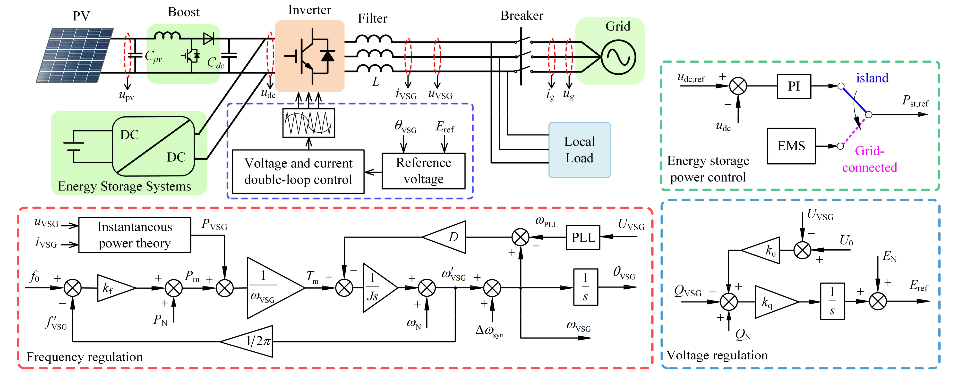
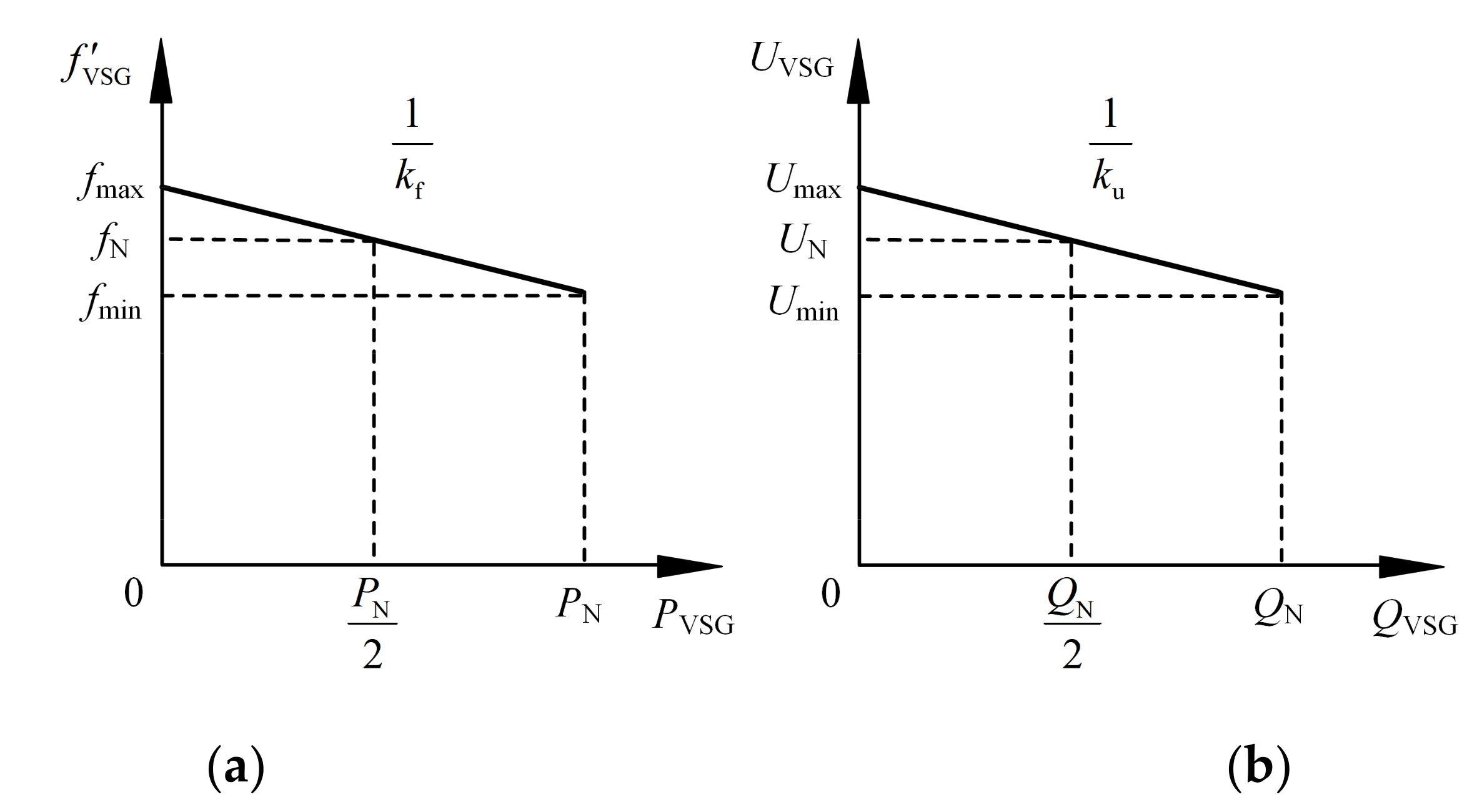
2. The Control Strategy of Voltage-Frequency Controlled VSG

Figure 1 shows the classic small-scale PV-battery energy storage system. The system has two operating conditions—off-grid operation and grid-connected operation—as follows: (1) Off-grid operation: In this operation condition, all of the energy required by the local load is provided by PV and energy storage. At this time, the control strategy adopted by the energy storage system (ESS) should use constant DC voltage control to ensure that the DC voltage of the inverter is stable at the rated value. According to the SOC state of energy storage, PV can work in MPPT mode or FPPT mode [28,29,30,31,32]. (2) Grid-connected operation: In this operation condition, the system is connected to the power grid. The energy stored power is controlled by the energy management system (EMS), and PV worked in MPPT mode. When the system has excess or insufficient power, it can transmit or absorb power from the grid, respectively.
The traditional control strategy of PV-BES adopts the VF control strategy in the off-grid operation condition and the current control strategy in the grid-connected operation condition, and thus needs to switch between the off-grid and grid-connected strategies. If the system adopts the VF source strategy in both off-grid and grid-connected situations, the switching time required by traditional strategies can be reduced, which can greatly improve the reliability of the system power supply.
The control structure of the voltage-frequency controlled VSG is shown in Figure 1. When the system operates in the off-grid condition, the voltage and frequency of the microgrid can be stabilized at the rated voltage and within the rated frequency range by adopting this control strategy. In the figure, D is the damping coefficient of VSG; J is the inertia coefficient of VSG; kf and ku are the droop coefficients of frequency-active power and voltage-reactive power, respectively; and Δωsyn is the pre-synchronous component. This component is non-zero only during pre-synchronization, and is zero when the system is connected to the grid or in island operation. The f-P droop control uses ωVSG as frequency feedback. Compared with using ωVSG as frequency feedback, the advantage of this method is that it can avoid the influence of the Δωsyn component in the pre-synchronization process. PN and QN are the active and reactive power, respectively, of the rated local load in the system.
The droop characteristic curve of the VF source in this study is shown in Figure 2. In Figure 2, fN is the rated frequency and UN is the rated voltage. When the system is in the off-grid condition, the power supply quality of the system must meet the requirements of the power quality standard. According to Figure 2, fmax and fmin, respectively, correspond to the two situations in which the local active load is 0 and the maximum. Similarly, Umin and Umax in Figure 2 correspond to the maximum and minimum local reactive power loads, respectively. The parameters selected in this paper are such that the frequency deviation is within the range of fN ± 0.5 Hz, and the AC voltage is within the range of UN ± 7%. Therefore, f0 and U0 in Figure 1 can be given as in Equation (1), and the two corresponding droop coefficients kf, ku can be given as in Equation (2).
f 0 = f N 0.5 U 0 = U N 7 % U N
k f = 2 × 0.5 P N k u = 2 × 7 % U N Q N

3. The Strategy of Grid-Connected Condition

In the grid-connected condition, the energy storage drops out of the control strategy of the constant DC bus voltage. The ESS controls the SOC level of energy storage based on EMS. When the SOC reaches a specified level, the storage is taken out of operation to reduce losses. When the system is in the grid-connected condition, the main purpose of the system is to send the excess electrical energy generated by PV into the grid, or to obtain energy from the power grid to meet the local load when the PV power is insufficient. Therefore, for different control purposes, the strategy can be divided into two control strategies: the active power control strategy and the reactive power control strategy.

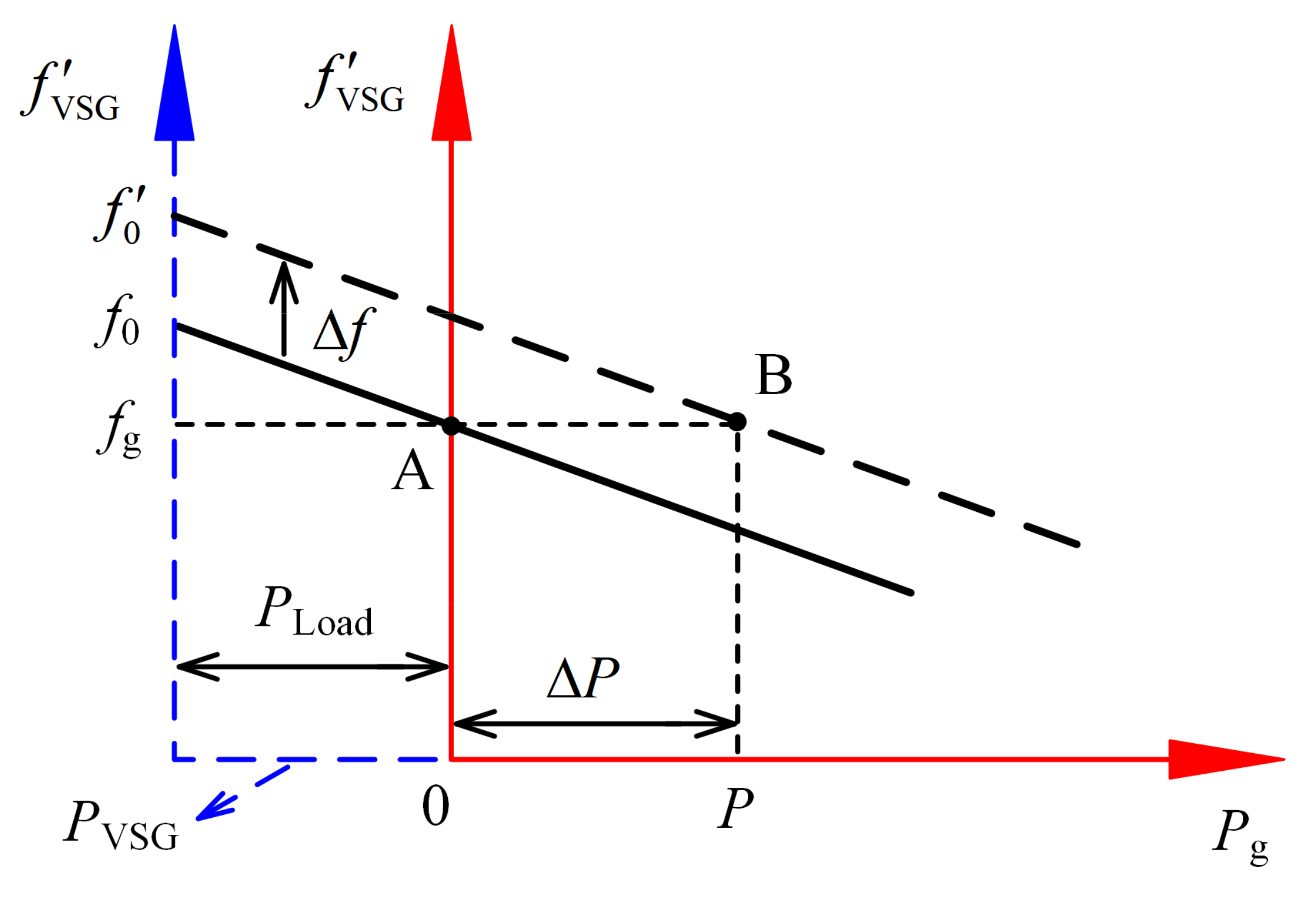
3.1. Active Power Control Strategy

After connecting to the grid, the system must change its output power to the grid. According to the f-P droop characteristic curve, the output power of the system to the grid can be changed by adjusting the position of the primary frequency regulation curve. As shown in Figure 3, point A is the grid connection point, and the system can be connected to the power grid without impact at this point. After connection to the grid, there is still no active power flow between the system and the grid. The transmission of power to the grid can be added via Δf on f0, and the primary frequency regulation curve of the VSG is equivalent to moving upward by Δf. In this manner, the intersection points of the VSG’s primary frequency regulation curve and the grid frequency fg (i.e., the operating point of the system) changes from point A to point B. When the system operates at point B, it transmits more active power, equal to ΔP, to the power grid than at point A, and its power value is ΔP = kf × Δf.
When all PV power is output to the grid, the frequency deviation Δf superimposed on f0 should be as in Equation (3).
Δ f = k d c , f ( u d c u d c , N )
where kdc,f is the proportionality coefficient for secondary frequency adjustment and is the rated inverter’s DC voltage. To ensure that the control strategy does not need to be switched when the system is connected to the grid and off the grid, a dead zone was added to the voltage deviation in Equation (3). This is shown in Equation (4), where Udz is the voltage dead zone, and the value in this study was 20 V. When the system is in the off-grid operation condition, the energy storage works in constant voltage mode, and the system voltage is constant at the rated voltage. According to Equation (4), the secondary adjustment of frequency has no effect at this time. Only when the energy storage exits the constant voltage mode after grid connection does the DC voltage deviation exceed the dead zone range, and the secondary frequency adjustment then takes effect.
Δ f = 0 , u d c u d c , N < u d z k d c , f ( u d c u d c , N u d z ) , u d c u d c , N u d z k d c , f ( u d c u d c , N + u d z ) , u d c u d c , N u d z
The VSG output power can be adjusted according to Equation (4). This control method provides regulation with steady-state error. Under the control of this strategy, the DC voltage is at different levels when the power changes. Therefore, the value of kdc,f must ensure that the DC voltage cannot exceed the maximum value (udc,max) that the hardware can withstand, as shown in Equation (5).
k d c , f P max 0.5 P N k f ( u d c , m a x u d c , N u d z )
where Pmax is the maximum output power of PV and ESS, and kf is the droop coefficient of VSG. The result calculated by Equation (5) is the minimum value of kdc,f.

3.2. Reactive Power Control Strategy

From the perspective of grid loss, the grid prefers to reduce the unnecessary flow of reactive power in the grid. Therefore, after the system is connected to the grid, the strategy should ensure that the reactive power between the system and the grid is zero. The reactive power control objectives after the system is connected to the grid are given in Equation (6).
Q g = k u ( U 0 U V S G )
where Qg is the reactive power exchanged between the system and the power grid. At the same time, the output power of the inverter must be within its rated capacity. Therefore, the value of QVSG must be less than Qlimit, and its calculation is given in Equation (7).
Q l i m i t = S 2 P V S G 2

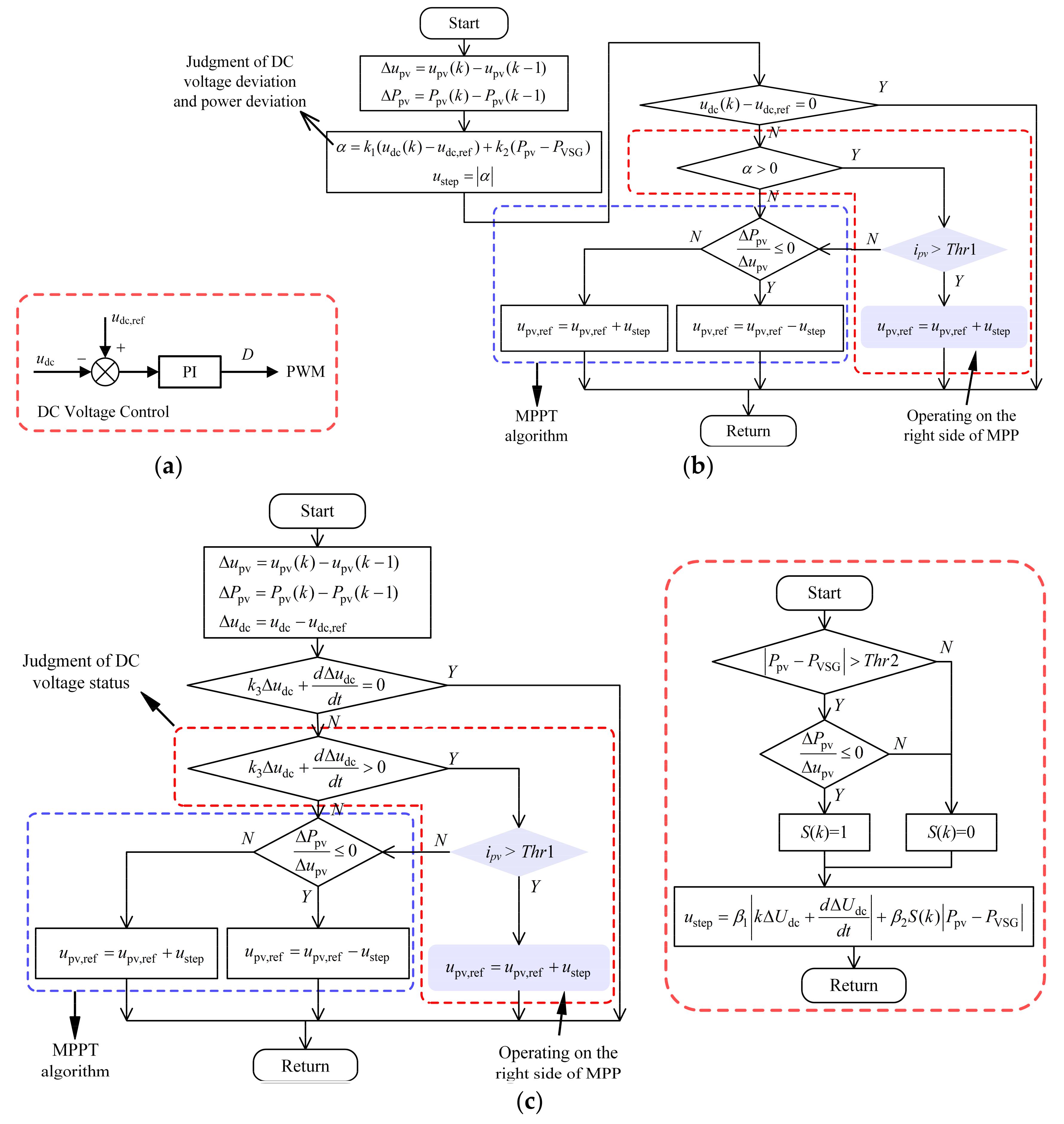
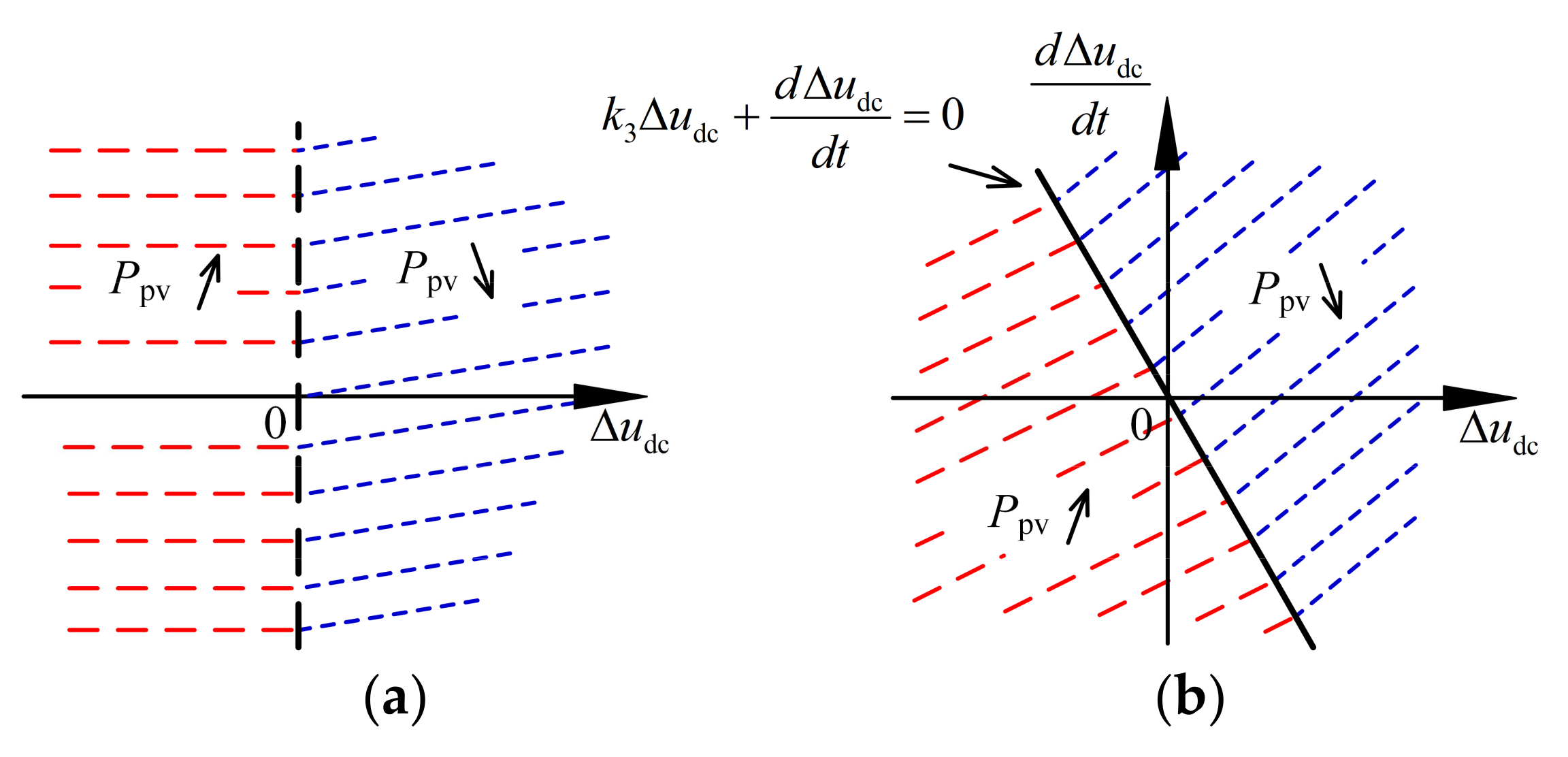
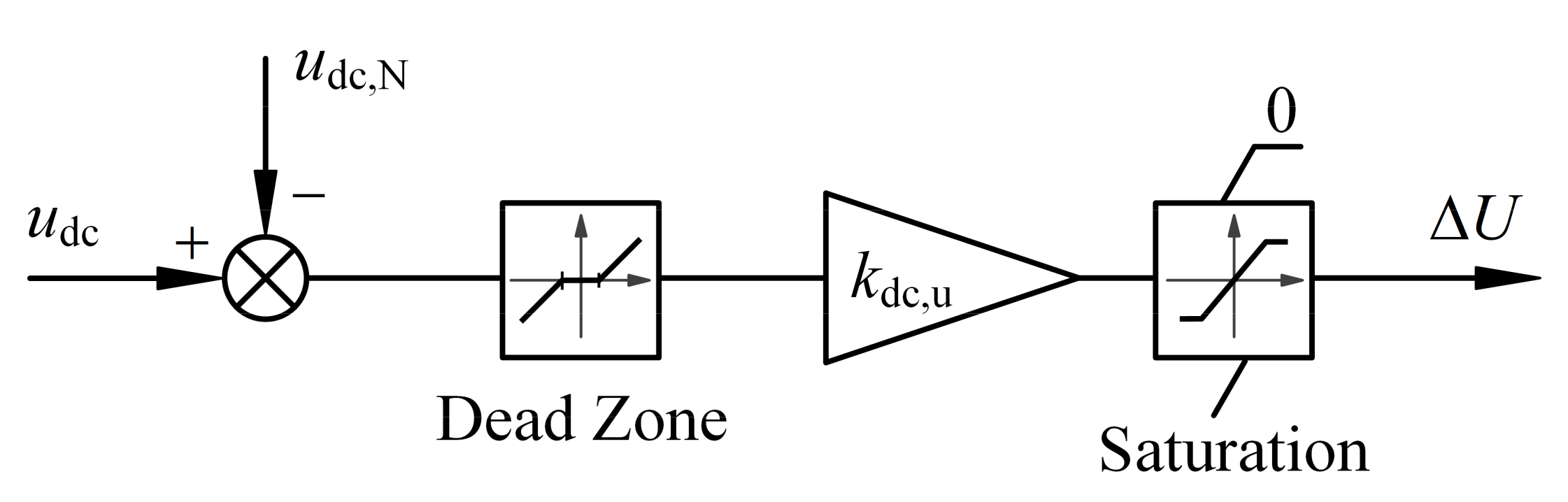
4. The Strategy of the Off-Grid Condition

Scenarios in which the system disconnects from the grid can generally be divided into two conditions. This first is normal off-grid or planned off-grid. In this condition, the system first starts the energy storage device and operates it in constant DC voltage mode, and then disconnects it from the grid. The other condition is unplanned off-grid. In this condition, the grid is often faulty, and the system is cut off from the grid after the anti-islanding protection is triggered [5,7]. Under this condition, the energy storage device may not have time to start. This leads to an imbalance between the DC and AC power of the inverter, which causes the DC voltage to increase or decrease rapidly. In addition, when the system is running off the grid, there may be over-discharge or overcharge of the energy storage battery. When the ESS cannot maintain a constant DC voltage, load fluctuations cause the DC voltage to become too high or too low.
To address this problem, an improved control strategy was proposed to correct the power imbalance when the system is off-grid. This problem can be studied under two conditions: sufficient light and insufficient light. These correspond to the conditions in which the PV power is greater than the load power and the PV power is less than the load power, respectively.

4.1. Sufficient Irradiance Condition

Under this condition, the PV power (Ppv) is greater than the load power, and the system faces the risk of excessive DC voltage. Because there is no power shortage in the system under this working condition, the stability of the DC voltage can be ensured only by using the control strategy. According to the PV P-V characteristic curve, the PV power can be changed by changing the PV voltage. PV has two operating areas, namely, on the left and right sides of the maximum power point (MPP) [28]. When the VSG power increases, the PV voltage (Upv) decreases. However, the PV curve’s dPpv/dUpv value on the left side of the MPP is greater than 0, and a drop in the PV voltage also causes the PV power to decrease. In this manner, a positive feedback is formed between the PV power and the PV voltage. The system must have a device (energy storage or inverter) that uses a constant DC voltage strategy to enable PV to operate on the left side of the MPP. The dPpv/dUpv on the curve to the right of MPP is less than 0 [28,29,30]. Therefore, when PV operates on the right-hand side of MPP, the system is stable regardless of whether there is a device working in constant DC voltage mode. Because energy storage cannot guarantee DC voltage stability under this condition, PV can only be selected to operate on the right-hand side of MPP.
According to the current theory, three control strategies are listed and compared in this paper. The principle of the three control strategies is shown in Figure 4.
Strategy 1: The PI controller is used to directly change the duty cycle D of the boost circuit according to the deviation of the DC voltage. This method changes the photovoltaic voltage by changing D. The advantage is that the control structure is simple and the control target is clear. However, due to the existence of the DC bus capacitance, the dynamic response of this strategy is slow. In addition, when the unbalanced power between the PV and the load is too large, the PV voltage will be close to the open circuit voltage of the PV panel. The dPpv/dUpv near the open circuit voltage of the PV panel is too large, which affects the stability of the system [29].
Strategy 2: This strategy is based on the flexible power point tracking (FPPT) strategy. The basis of the strategy is to add the judgment of the DC voltage to the basis of the MPPT strategy [30] by increasing the PV voltage when the DC voltage is higher than the reference DC voltage. The MPPT strategy is executed when the DC voltage is lower than the reference DC voltage. According to the current operating point, the ΔPpvupv information is used to choose to increase or decrease the PV voltage. The judgment condition for the voltage adjustment of Strategy 2 is shown in Equation (8), where k1 and k2 are the weighting factors of voltage deviation and power deterioration. In Equation (8), Ppv is the PV power and PVSG is the output power of VSG. In addition, Equation (8) is also a variable step-size equation of the strategy, and changing the tracking step-size according to its value can achieve a better tracking effect [33]. Compared with Strategy 1, this method also adds the judgment of the PV current to prevent the PV current from being too small, because the smaller the PV current, the closer the PV operating point to the PV open circuit point. When the PV operating point is too close to the PV open circuit point, there is a risk of PV power oscillating.
α = k 1 ( u d c u d c , r e f ) + k 2 ( P p v P V S G )
The advantage of this strategy is that the PV can be accurately controlled to operate on the right-hand side of the MPP, which can prevent the PV voltage from approaching the PV’s open circuit voltage. However, this strategy still has the problem of slow dynamic response. As shown in Figure 5a, although Strategy 2 considers the deviation of power, Strategies 1 and 2 still do not consider the rate of the inverter’s DC voltage. The strategy only considers the DC voltage deviation and does not consider the rate of change in the DC voltage; therefore, the DC voltage cannot be controlled quickly and accurately.
Strategy 3: This strategy is based on an improvement of Strategy 2. The rate of change in the DC voltage is added to the judgment condition, which is shown in Equation (9). In Equation (9), Δudc is the deviation between the inverter’s DC voltage and the reference voltage. Equation (9) corresponds to the blue area in Figure 5b above the straight line. When Equation (9) is less than 0, the corresponding area is the red area below the line in Figure 5b. The slope of the dividing line of the two regions in Figure 5b is −k3.
k 3 Δ u d c + d Δ u d c d t > 0
When Equation (9) is satisfied, the photovoltaic power should be increased. According to the characteristics of the curve to the right of MPP, reducing the PV power requires increasing the PV voltage. When Equation (9) is not satisfied, the MPPT strategy is executed. According to the current operating point, the ΔPpvUpv information is used to choose to increase or decrease the PV voltage. In addition, the improved variable step-size calculation method is as shown in Equation (10). This variable step strategy not only considers the DC voltage information, but also considers the deviation between the VSG output power and the PV power. In the off-grid state, the output power of the voltage-frequency controlled VSG is affected by the local load. Therefore, when the PV power is much greater than the output power of the VSG, it is necessary to quickly change the PV operating point to ensure the power balance between the DC side and the AC side of the inverter.
u s t e p = β 1 k Δ u d c + d Δ u d c d t + β 2 S ( k ) P p v P V S G
where β1 and β2 are acceleration factors corresponding to different items, and S(k) is a switching function. When the PV power is much larger than the local load power (i.e., the VSG output power Pvsg), a larger tracking step-size is needed to make the deviation between Ppv and Pvsg reduce quickly. Thus, as shown in Figure 4c, S(k) is equal to 1 only when the deviation between the PV power and the VSG power is greater than Thr2, and PV is operating on the right-hand side of MPP. Otherwise, S(k) is equal to zero. When PV is operating on the right-hand side of MPP, the calculation method of S(k) is as shown in Equation (11).
S ( k ) = 1 , P p v P V S G T h r 2 0 , P p v P V S G < T h r 2
The advantage of this strategy is that it cannot only avoid the issue of the PV voltage being close to the open circuit voltage, but it also quickly stabilizes the DC voltage. Its dynamic response speed is greatly improved compared with those of Strategies 1 and 2.
It is worth mentioning that this strategy is proposed for boost circuits. Due to the presence of DC capacitors, the inverter and the PV circuit are decoupled. There is no correlation between the PV strategy and the inverter control strategy. Therefore, this PV strategy is not only applicable to the condition examined in this study.

4.2. Insufficient Irradiance Condition

When the PV power is insufficient, the system cannot provide enough energy. At this time, it can aim to maintain the load without electricity, and wait for input from the energy storage to provide energy support for the load. Then, the system will not de-load, and the power voltage can be quickly restored after the energy storage is put into operation, which can effectively improve the reliability of the system’s power supply.
Considering that the load power of the system is related to the voltage when the system is running off the grid (even the power of a resistive load usually depends on the voltage across the load), in the off-grid operating condition, the output power of the VSG can be adjusted by reducing the output voltage to achieve a good match between the output power and the load power. In this study, a ΔU component was added on the voltage loop, which is proportional to the DC voltage deviation, and its control structure is shown in Figure 6. This voltage component ΔU is 0 when the system is connected to the grid, and only exists when the system is running off the grid. In Figure 6, kdc,u is the proportionality coefficient between ΔU and the DC voltage deviation where the voltage dead zone is consistent with the voltage dead zone Udz in Equation (4), and the value is 20 V.

5. The Parameters of the Simulation Model

We used Simulink to build the model shown in Figure 1 to verify the strategy proposed in this study. The rated active power of the local load in this system is 10 kW and the reactive power is 2 kVar. The maximum charging power of the energy storage battery is 10 kW, and the discharging power is 15 kW. The possible maximum power of the PV panel is 15 kW; therefore, the maximum active power output by the inverter is 30 kW, and the maximum active power that can be absorbed is 10 kW. In this study, the normal operating range of DC voltage was selected as 700–900 V. Therefore, according to the power and DC voltage range, the calculated value of kdc,f should be 0.025. The detailed parameters of the PV-BES system are shown in Table 1, and the parameters of the proposed strategy are shown in Table 2.

6. The Analysis of the Simulation

To verify the accuracy of the strategy in this study, simulation was used to validate the on-grid and off-grid processes of the system. For different processes, the load or power demand changes, PV maximum power changes, and other working conditions were set separately. The analysis of the simulation is as follows.

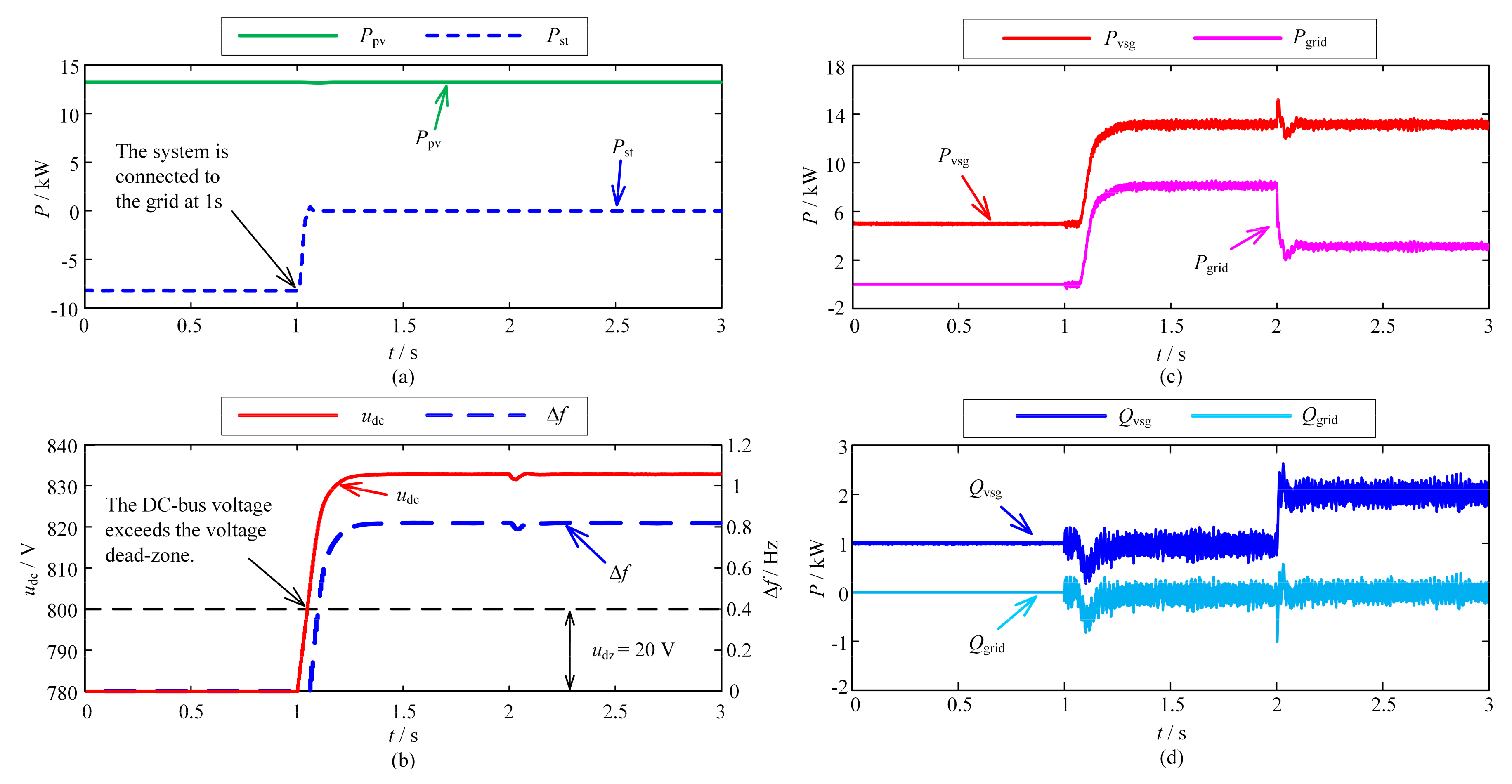
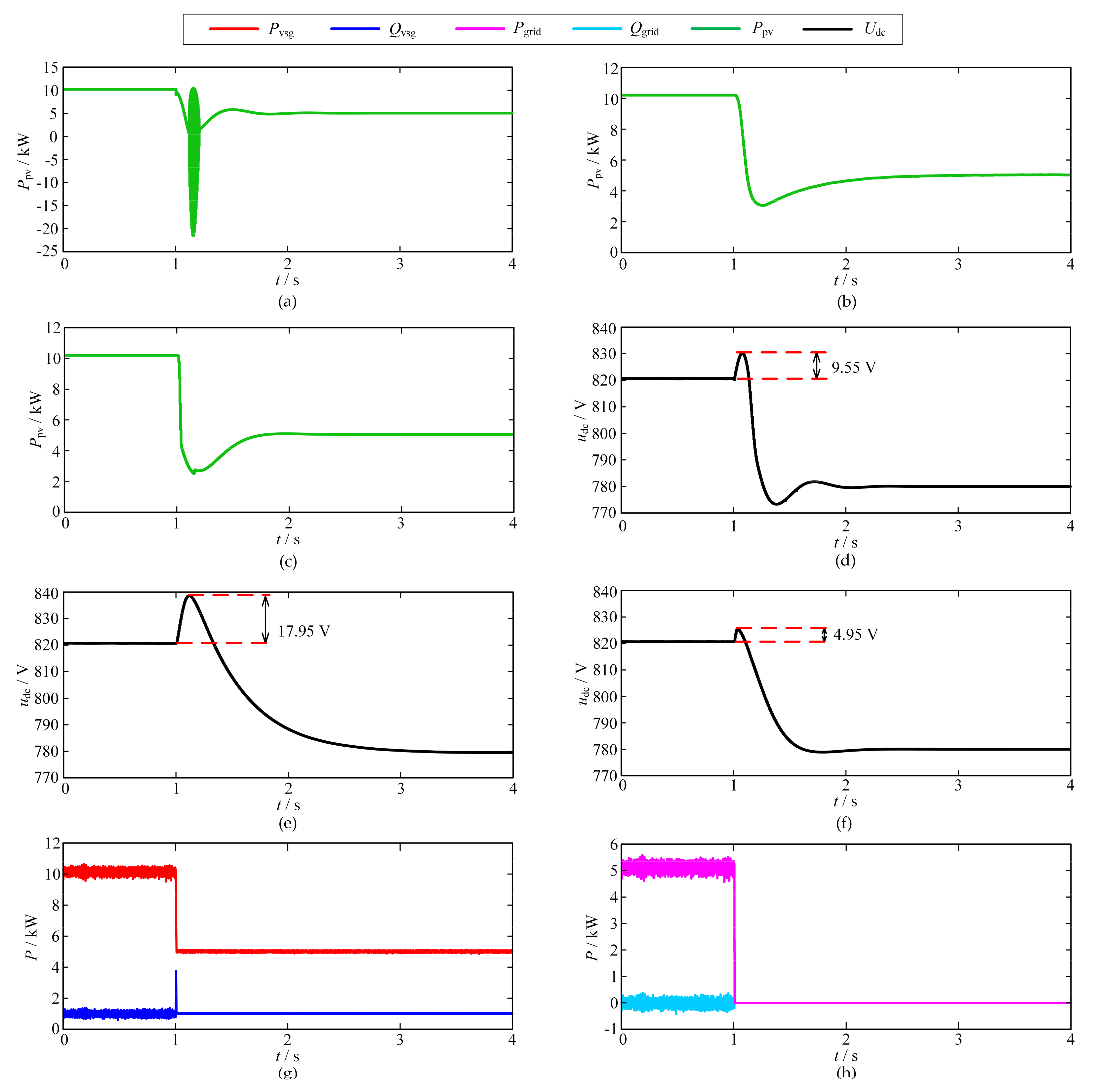
6.1. Verification of Grid-Connected Control Strategy

The purpose of grid connection is mainly to deliver PV power to the grid or charge energy storage batteries. Two working conditions were set to verify the grid-connection strategy.
Condition 1: The temperature of the PV irradiance does not change, which means the maximum power of the PV does not change. At 1 s, the system was connected to the grid, and then the energy storage battery exited operation. At 0–2 s, the local load active power and reactive power of the system were 5 kW and 1 kVar, respectively. At 2 s, the local load added the power of 5 kW and 1 kVar, respectively; therefore, the local load at 2–3 s was 10 kW and 2 kVar. The simulation results under this condition are shown in Figure 7. Figure 7a shows the changes in the output power of PV and ESS (i.e., energy storage batteries), where the power of the energy storage is set to discharge as positive and charge as negative. Figure 7b shows the change in the inverter’s DC voltage and Δf in the secondary frequency adjustment. Figure 7c shows the active power output by the VSG and the active power transmitted between the system and the grid. Figure 7d shows the reactive power output by the VSG and the reactive power transmitted between the system and the grid.
It can be seen from Figure 7a that the PV power under this condition was 13.2 kW. The ESS absorbed about 8.2 kW of power in the first 1 s, and the power of the ESS was adjusted to 0 after the connection of the grid. The ESS absorbed about 8.2 kW of power in the first 1 s, and the output power of the ESS became 0 after the system was connected to the grid. When the system was connected to the grid, the exit of the ESS caused the inverter input power to be greater than the output power. Therefore, the DC voltage of the inverter continued to rise. It can be seen from Figure 7b that when the DC voltage exceeded the voltage dead zone (i.e., 800 V) at about 1.06 s, Δf started to change with the voltage. Finally, when the DC voltage reached 832.8 V and Δf reached 0.82, the system became stable, and the power of the AC and DC sides of the inverter were balanced. It can be seen from Figure 7c that the output power of the inverter after grid connection was the PV power; therefore, the output power of the VSG was almost unchanged. At 1–2 s, the local load was 5 kW and 1 kVar; therefore, the power delivered by the system to the grid was about 8 kW after the voltage stabilized. At 2–3 s, the local load was 10 kW and 2 kVar; therefore, the output power of the system to the grid changed from 8 to 3 kW. The goal of the reactive power control strategy in this study was to minimize the reactive power exchange between the grid and the system. Therefore, it can be seen from Figure 7d that when the local reactive load changed, the reactive power of the VSG changed from 1 to 2 kVar. The reactive power output from the system to the grid was 0.
Condition 2: The local load stayed the same, and the active power and reactive power were 5 kW and 1 kVar, respectively. At 1 s, the system was connected to the grid, and then the ESS was charged with maximum power after grid connection. At 2–4 s, the irradiance gradually changed from 800 to 100 W/m2. The simulation results under this condition are shown in Figure 8. Figure 8a shows the changes in the output power of PV and ESS. Figure 8b shows the change in the inverter’s DC voltage and Δf in the secondary frequency adjustment. Figure 8c shows the active power output by the VSG and the active power transmitted between the system and the grid. Figure 8d shows the reactive power output by the VSG and the reactive power transmitted between the system and the grid.
It can be seen from Figure 8a that the initial PV output under condition 2 was about 8.16 kW. The PV power decreased gradually between 2 and 4 s, and the PV power decreased to about 0.92 kW at 4 s. The power of the ESS in the first 1 s was about −3.24 kW, and the ESS was charged with power of 10 kW after the system was connected to the grid. When connected to the grid, the ESS was charged with maximum power, causing the inverter input power to be less than the output power. Therefore, the DC voltage of the inverter continued to drop.
It can be seen from Figure 8b that when the DC voltage exceeded the voltage dead zone (i.e., 760 V) at about 1.06 s, Δf started to change with the voltage. At about 1.2 s, the DC voltage reached 732.5 V and Δf reached −0.69. At this time, the inverter’s power of the AC and DC sides was balanced. After 4 s, the irradiance reached 100 W/m2, and the photovoltaic output power no longer dropped. Then, the DC voltage reached 703.4 V and Δf reached −1.415. The AC and DC side power of the inverter reached a new balance point. It can be seen from Figure 8c,d that the local load was 5 kW and 1 kVar between 0 and 7 s. Therefore, the power output from the system to the grid was 5 kW lower than the output power of the VSG. The voltage was stable at about 1.2 s; at this time, the power transmitted by the system to the grid was about −6.9 kW. The irradiance no longer changed after 4 s, and the final power transmitted by the system to the grid was about −14.1 kW.

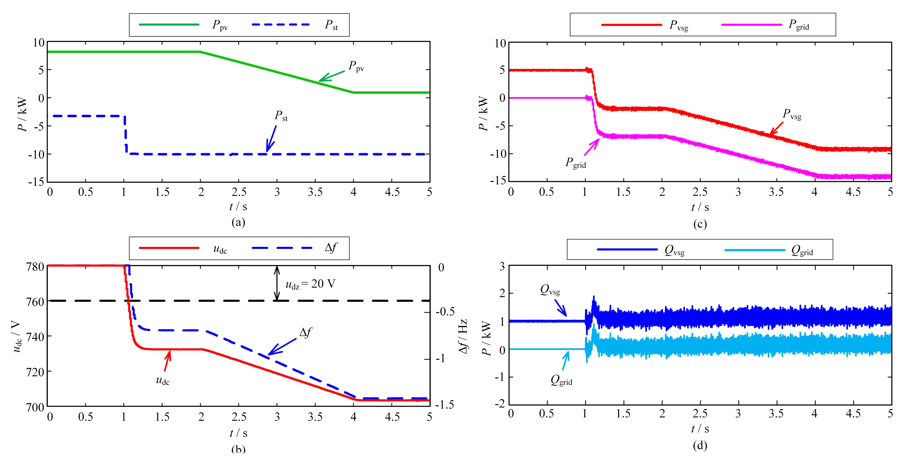
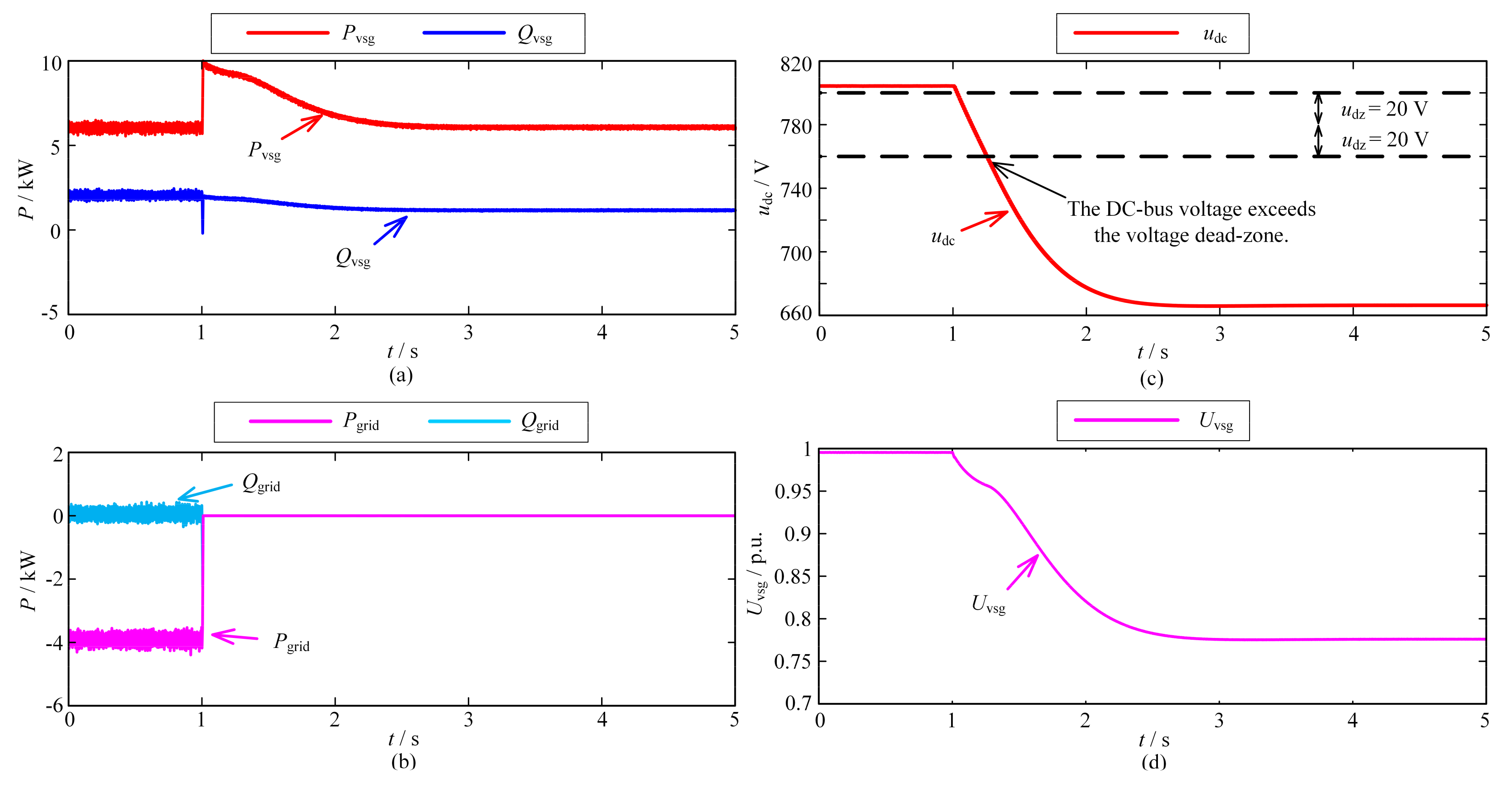
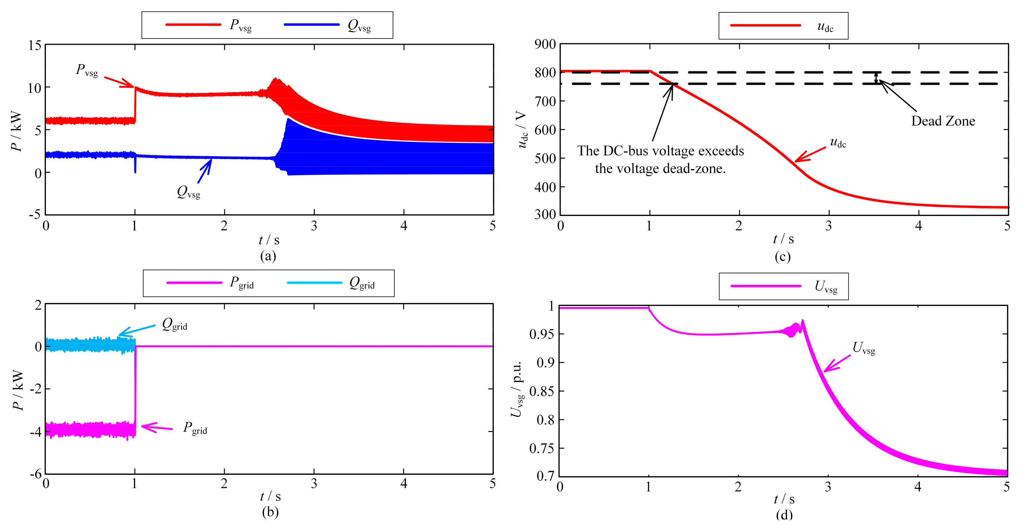
6.2. Verification of Off-Grid Control Strategy

When an unexpected off-grid condition occurs or the energy storage system fails to operate normally when off-grid, the PV-BES may not be able to guarantee the power supply quality of the load. At this point, the main purpose of PV-BES should be to try to ensure that the local load is continuously powered. By waiting until the system has enough energy to supply power to the local load, the system can quickly restore power to the load. According to whether the irradiance is sufficient, two working conditions were set to verify the off-grid control strategy.
Condition with sufficient irradiance: Under this condition, the active power and reactive power of the local load were 5 kW and 1 kVar, respectively. At 1 s, the system was disconnected from the power grid, and the system changed from the grid-connected state to the off-grid operation state. The irradiance in the 0–5 s period was 1000 W/m2, and the photovoltaic output under this irradiance was about 10.2 kW. During this period, energy storage was in a non-working or unavailable state. Figure 9 shows the response process of the output power and DC voltage of the system under the control of three different strategies. Figure 9a,d shows the response processes of PV power and inverter DC voltage under the control of Strategy 1. Similarly, Figure 9b,e shows the response process of the system under the control of Strategy 2, and Figure 9c,f shows the response process of the system under the control of Strategy 3. Figure 9g shows the changes in the active power and reactive power output by the VSG under this working condition. Figure 9h shows the changes in active power and reactive power transmitted by the system to the grid.
Because the power of the energy storage was 0 under this condition, the power output from the system to the grid after grid connection was PV power (i.e., 10.2 kW). When the grid was disconnected from the system, the output power of the VSG became the local load power (i.e., 5 kW). At this time, the output power of PV was still 10.2 kW; therefore the DC voltage of the inverter rose rapidly. Comparing the response process of the system under the control of the three strategies, it can be seen that the dynamic response process of the system under the control of Strategy 3, taking into account the DC voltage change rate, is the best. It can be seen from Figure 9a that Strategy 1 does not consider the PV P-V characteristics; therefore, when the PV voltage was close to the open circuit voltage, the PV power oscillated. In comparison, Strategies 2 and 3, which take PV characteristics into account, avoid this problem during the system response process. Comparing Figure 9d–f, it can be seen that the DC voltage under the control of the three strategies rose to different degrees. For example, the magnitude of the difference between the DC voltage immediately before the system is disconnected from the grid and the maximum DC voltage after the disconnection reflects the response speed of the strategy. The DC voltage under the control of Strategy 1 increased by 9.55 V, the DC voltage under the control of Strategy 2 increased by 17.95 V, and the DC voltage under the control of Strategy 3 only exceeded 4.95 V. The result shows that the effect of Strategy 3 is the best among the three strategies; not only is the response speed fast, but the time required to stabilize the DC voltage is short.
Insufficient irradiance condition: Under this condition, the active power and reactive power of the local load were 10 kW and 2 kVar, respectively. At 1 s, the system was disconnected from the power grid, and the system changed from the grid-connected state to the off-grid operation state. The irradiance in the 0–5 s period was 600 W/m2, and the PV output under this irradiance was about 6.1 kW. During this period, energy storage had been in a non-working or unavailable state. To prove the effectiveness of the proposed strategy, a simulation was carried out both under the proposed strategy control and without the strategy control. The simulation results of this condition under the control of the proposed strategy are shown in Figure 10. The simulation results of this condition without the control strategy are shown in Figure 11. Figure 10a and Figure 11a show the active and reactive power output by the VSG. Figure 10b and Figure 11b show the active and reactive power flowing between the system and the grid. Figure 10c and Figure 11c show the changes in the DC voltage of the inverter. Figure 10d and Figure 11d show the change in the voltage on the AC side of the VSG. The voltage uses the per unit value and its base line value is 380 V.
It can be seen from Figure 10 that the system finally reached a stable state under the control of the proposed strategy. When the system was stable, the DC voltage remained at 682.3 V. It can be seen from Figure 10a,d that the load power was affected by the AC voltage amplitude, which changed with the voltage amplitude. When the AC voltage dropped to about 0.776, the load power was consistent with the PV power, and the DC voltage also reached a stable value.
Figure 11 shows the simulation results of the model without the proposed control strategy. The inverter DC voltage was finally reduced to around 330 V, which was lower than the minimum voltage required for the inverter to operate normally. Therefore, the AC voltage and output power of the inverter oscillated at 2.6 s. Comparing the simulation results of Figure 10 and Figure 11, it can be seen that the control strategy proposed in this paper is able to stabilize the DC voltage when the irradiance is insufficient, and improve the reliability of the system.

7. Conclusions

Based on the VF source-type VSG control strategy, this study proposed a united control strategy to address PV-BES off-grid and grid-connected issues. According to the characteristics of the VF source, the grid-connected control strategy realizes the change in the output power through the secondary adjustment of the frequency. In this control strategy, the system can avoid switching the control mode when grid-connected and off-grid. In addition, the strategy takes into account the power generation characteristics of PV. When grid-connected, the strategy can change the power delivered by the VSG to the grid according to the PV power and the ESS power. In the off-grid state, when the energy storage system is unable to work normally, the proposed strategy can solve the problem of excessively high or low DC voltage. Finally, a PV-BES model was built using MATLAB-Simulink and the proposed strategy was verified. The simulation results showed that the grid-connected control strategy can deliver PV power to the grid, or absorb energy from the grid to charge the energy storage system, without switching the control mode. In addition, the results also showed that when the ESS fails to work normally, the off-grid control strategy can quickly achieve the power balance between the DC power and AC power of the inverter to stabilize the inverter’s DC voltage.

Author Contributions

Each author contributed extensively to the preparation of this manuscript. C.W. and X.Y. designed and developed the main research work, including designing the controller, and simulation model. H.M., X.W. and B.L. has worked on the analysis of the obtained results and writing original draft. X.W., Z.W. and H.M. provided some useful suggestions in organizing research contents and the construction of a paper. All the authors revised and approved the publication. C.W. wrote the paper. All authors have read and agreed to the published version of the manuscript.

Funding

This paper was supported by the General Projects of Beijing Natural Science Foundation (3212037); Natural Science Funding of Hebei Province (E2018502134).

Acknowledgments

The authors gratefully thank the financial supports by the General Projects of Beijing Natural Science Foundation (3212037) and Natural Science Funding of Hebei Province (E2018502134). The authors of the article appreciate the valuable suggestions of the referees, which contributed to improving the paper.

Conflicts of Interest

The authors declare no conflict of interest.

References

  1. Renewables 2020: Global Status Report (GSR). Available online: http://www.ren21.net/ (accessed on 16 June 2020).
  2. Li, X.; Yao, L.; Hui, D. Optimal control and management of a large-scale battery energy storage system to mitigate fluc-tuation and intermittence of renewable generations. J. Mod. Power Syst. Clean Energy 2016, 4, 593–603. [Google Scholar] [CrossRef] [Green Version]
  3. Lu, X.; Sun, K.; Guerrero, J.; Vasquez, J.C.; Huang, L. State-of-Charge Balance Using Adaptive Droop Control for Distributed Energy Storage Systems in DC Microgrid Applications. IEEE Trans. Ind. Electron. 2014, 61, 2804–2815. [Google Scholar] [CrossRef] [Green Version]
  4. Datta, U.; Kalam, A.; Shi, J. Battery Energy Storage System Control for Mitigating PV Penetration Impact on Primary Fre-quency Control and State-of-Charge Recovery. IEEE Trans. Sustain. 2020, 11, 746–757. [Google Scholar] [CrossRef] [Green Version]
  5. Yang, Y.; Enjeti, P.; Blaabjerg, F.; Wang, H. Wide-Scale Adoption of Photovoltaic Energy: Grid Code Modifications Are Explored in the Distribution Grid. IEEE Ind. Appl. Mag. 2015, 21, 21–31. [Google Scholar] [CrossRef] [Green Version]
  6. Mao, M.; Qian, C.; Ding, Y. Decentralized coordination power control for islanding microgrid based on PV/BES-VSG. CPSS Trans. Power Electron. Appl. 2018, 3, 14–24. [Google Scholar] [CrossRef]
  7. Narayanan, V.; Kewat, S.; Singh, B. Solar PV-BES Based Microgrid System With Multifunctional VSC. IEEE Trans. Ind. Appl. 2020, 56, 2957–2967. [Google Scholar] [CrossRef]
  8. Du, W.; Jiang, Q.; Erickson, M.J.; Lasseter, R.H. Voltage-Source Control of PV Inverter in a CERTS Microgrid. IEEE Trans. Power Deliv. 2014, 29, 1726–1734. [Google Scholar] [CrossRef]
  9. Bhattacharyya, S.; Kumar, P.D.S.; Samanta, S. Steady Output and Fast Tracking MPPT (SOFT-MPPT) for P&O and InC Algorithms. IEEE Trans. Sustain. Energy 2021, 12, 293–302. [Google Scholar]
  10. Arafat, M.N.; Palle, S.; Sozer, Y. Transition control strategy between standalone and grid-connected operations of volt-age-source inverters. IEEE Trans. Ind. Appl. 2012, 48, 1516–1525. [Google Scholar] [CrossRef]
  11. Li, X.; Zhang, H.; Shadmand, M.B.; Balog, R.S. Model predictive control of a voltage-source inverter with seamless transition be-tween islanded and grid-connected operations. IEEE Trans. Ind. Electron. 2017, 64, 7906–7918. [Google Scholar] [CrossRef]
  12. Kumar, S.; Singh, B. Seamless Operation and Control of Single-Phase Hybrid PV-BES-Utility Synchronized System. IEEE Trans. Ind. Appl. 2019, 55, 1072–1082. [Google Scholar] [CrossRef]
  13. Zhong, Q.-C.; Nguyen, P.-L.; Ma, Z.; Sheng, W. Self-Synchronized Synchronverters: Inverters Without a Dedicated Synchronization Unit. IEEE Trans. Power Electron. 2014, 29, 619–630. [Google Scholar] [CrossRef]
  14. Zhong, Q.-C. Power-Electronics-Enabled Autonomous Power Systems: Architecture and Technical Routes. IEEE Trans. Ind. Electron. 2017, 64, 5907–5918. [Google Scholar] [CrossRef]
  15. Hashmi, K.; Khan, M.M.; Jiang, H.; Shahid, M.U.; Habib, S.; Faiz, M.T.; Tang, H. A Virtual Micro-Islanding-Based Control Paradigm for Renewable Microgrids. Electronics 2018, 7, 105. [Google Scholar] [CrossRef] [Green Version]
  16. Bai, X.; Miao, H.; Zeng, C. Improved Droop Control Strategy for Reactive Power Sharing of Parallel Inverters in Low-Voltage Microgrid. In Proceedings of the 2019 IEEE Innovative Smart Grid Technologies-Asia (ISGT Asia), Chengdu, China, 21–24 May 2019; pp. 2538–2543. [Google Scholar]
  17. Zhang, H.; Kim, S.; Sun, Q.; Zhou, J. Distributed Adaptive Virtual Impedance Control for Accurate Reactive Power Sharing Based on Consensus Control in Microgrids. IEEE Trans. Smart Grid 2017, 8, 1749–1761. [Google Scholar] [CrossRef]
  18. Pranjal, S.; Navdeep, S.; Kumar Pandey, A. Investigating the frequency fault ride-through capability of solar photovoltaic system: Replacing battery via virtual inertia reserve. Int. T. Electr. Energy. 2021, 31, e12791. [Google Scholar]
  19. Huang, L.; Xin, H.; Wang, Z. Damping Low-Frequency Oscillations Through VSC-HVDC Stations Operated as Virtual Syn-chronous Machines. IEEE Trans. Power Electron. 2019, 34, 5803–5818. [Google Scholar] [CrossRef]
  20. Dong, S.; Chen, Y.C. A Method to Directly Compute Synchronverter Parameters for Desired Dynamic Response. IEEE Trans. Energy Convers. 2018, 33, 814–825. [Google Scholar] [CrossRef]
  21. Rasool, A.; Yan, X.; Rasool, H.; Guo, H.; Asif, M. VSG Stability and Coordination Enhancement under Emergency Condition. Electronics 2018, 7, 202. [Google Scholar] [CrossRef] [Green Version]
  22. Rehman, H.U.; Yan, X.; Abdelbaky, M.A.; Jan, M.U.; Iqbal, S. An advanced virtual synchronous generator control technique for frequency regulation of grid-connected PV system. Int. J. Electr. Power Energy Syst. 2021, 125, 106440. [Google Scholar] [CrossRef]
  23. Wu, X.; Shen, C.; Iravani, R. Feasible Range and Optimal Value of the Virtual Impedance for Droop-Based Control of Mi-crogrids. IEEE Trans. Smart Grid. 2017, 8, 1242–1251. [Google Scholar] [CrossRef]
  24. Liu, J.; Miura, Y.; Bevrani, H.; Ise, T. A Unified Modeling Method of Virtual Synchronous Generator for Multi-Operation-Mode Analyses. IEEE J. Emerg. Sel. Top. Power Electron. 2021, 9, 2394–2409. [Google Scholar] [CrossRef]
  25. Liu, J.; Miura, Y.; Ise, T. Comparison of Dynamic Characteristics Between Virtual Synchronous Generator and Droop Control in Inverter-Based Distributed Generators. IEEE Trans. Power Electron. 2016, 31, 3600–3611. [Google Scholar] [CrossRef]
  26. Ali, H.; Hussain, A.; Bui, V.-H.; Kim, H.-M. Consensus Algorithm-Based Distributed Operation of Microgrids During Grid-Connected and Islanded Modes. IEEE Access 2020, 8, 78151–78165. [Google Scholar] [CrossRef]
  27. Lee, J.; Lee, S.; Lee, K. Multistage Stochastic Optimization for Microgrid Operation Under Islanding Uncertainty. IEEE Trans. Smart Grid 2021, 12, 56–66. [Google Scholar] [CrossRef]
  28. Hoke, A.F.; Shirazi, M.; Chakraborty, S.; Muljadi, E.; Maksimovic, D. Rapid Active Power Control of Photovoltaic Systems for Grid Frequency Sup-port. IEEE J. Emerg. Sel. Topics Power Electron. 2017, 5, 1154–1163. [Google Scholar] [CrossRef]
  29. Tafti, H.D.; Konstantinou, G.; Townsend, C.D.; Farivar, G.G.; Sangwongwanich, A.; Yang, Y.; Pou, J.; Blaabjerg, F. Extended Functionalities of Photovoltaic Systems With Flexible Power Point Tracking: Recent Advances. IEEE Trans. Power Electron. 2020, 35, 9342–9356. [Google Scholar] [CrossRef]
  30. Tafti, H.D.; Sangwongwanich, A.; Yang, Y.; Pou, J.; Konstantinou, G.; Blaabjerg, F. An Adaptive Control Scheme for Flexible Power Point Tracking in Photo-voltaic Systems. IEEE Trans. Power Electron. 2019, 34, 5451–5463. [Google Scholar] [CrossRef] [Green Version]
  31. Sangwongwanich, A.; Yang, Y.; Blaabjerg, F. A Sensorless Power Reserve Control Strategy for Two-Stage Grid-Connected PV Systems. IEEE Trans. Power Electron. 2017, 32, 8559–8569. [Google Scholar] [CrossRef] [Green Version]
  32. Zhong, C.; Zhou, Y.; Zhang, X.; Yan, G. Flexible power-point-tracking-based frequency regulation strategy for PV system. IET Renew. Power Gener. 2020, 14, 1797–1807. [Google Scholar] [CrossRef]
  33. Loukriz, A.; Haddadi, M.; Messalti, S. Simulation and experimental design of a new advanced variable step size Incremental Conductance MPPT algorithm for PV systems. ISA Trans. 2016, 62, 30–38. [Google Scholar] [CrossRef] [PubMed]
Figure 1. The structure and control strategy of the PV-BES (photovoltaic-battery energy storage system).
Electronics 10 02047 g001
Figure 2. Voltage-frequency controlled VSG (virtual synchronous generator) droop characteristic curve. (a) f-P droop curve. (b) U-Q droop curve.
Electronics 10 02047 g002
Figure 3. Frequency secondary adjustment is used to change the output power.
Electronics 10 02047 g003
Figure 4. Three different strategies to stabilize the inverter DC voltage by changing PV power. (a) Control strategy 1. (b) Control strategy 2. (c) Control strategy 3.
Electronics 10 02047 g004
Figure 5. The basic principles of different methods for stabilizing DC voltage. (a) Only the DC voltage deviation is considered. (b) The deviation of DC voltage and the rate of DC voltage are considered.
Electronics 10 02047 g005
Figure 6. Calculation method of the ΔU component.
Electronics 10 02047 g006
Figure 7. The change process of power, DC voltage, and Δf under condition 1. (a) The output power of PV and ESS. (b) The inverter’s DC voltage and Δf in the secondary frequency adjustment. (c) The active power output by the VSG and the active power transmitted between the system and the grid. (d) The reactive power output by the VSG and the reactive power transmitted between the system and the grid.
Electronics 10 02047 g007
Figure 8. The change process of power, DC voltage, and Δf under condition 2. (a) The output power of PV and ESS. (b) The inverter’s DC voltage and Δf in the secondary frequency adjustment. (c) The active power output by the VSG and the active power transmitted between the system and the grid. (d) The reactive power output by the VSG and the reactive power transmitted between the system and the grid.
Electronics 10 02047 g008
Figure 9. Changes in system voltage and power under the proposed strategy when the irradiance is sufficient. (a) The change process of PV power under the control of Strategy 1. (b) The change process of PV power under the control of Strategy 2. (c) The change process of PV power under the control of Strategy 3. (d) The change process of DC voltage under the control of Strategy 1. (e) The change process of DC voltage under the control of Strategy 2. (f) The change process of DC voltage under the control of Strategy 3. (g) The changes in VSG output power. (h) The changes in active power and reactive power transmitted by the system to the grid.
Electronics 10 02047 g009
Figure 10. Changes in system voltage and power under the proposed strategy when the irradiance is insufficient. (a) The active and reactive power output by the VSG. (b) The active and reactive power transmitted between the system and the grid. (c) The inverter’s DC voltage. (d) The per unit voltage on the AC side of the VSG.
Electronics 10 02047 g010
Figure 11. Changes in system voltage and power without control strategy when the irradiance is insufficient. (a) The active and reactive power output by the VSG. (b) The active and reactive power transmitted between the system and the grid. (c) The inverter’s DC voltage. (d) The per unit voltage on the AC side of the VSG.
Electronics 10 02047 g011
Table 1. Parameters of the PV-BES system.
ParameterValue
Possible PV maximum power15 kW
Maximum charging power of energy storage system10 kW
Maximum discharge power of energy storage system15 kW
Grid voltage6.6 kV
Inverter AC voltage250 V
P&O algorithm tracking frequency200 Hz
Rated DC-bus voltage (Udc,N)780 V
Table 2. Parameters of the proposed strategy.
ClassificationParameterValue
VSG parameters The droop coefficient of frequency-active power (kf)10,000
The droop coefficient of voltage-reactive power (ku)66.67
VSG inertia and damping (J, D)0.1, 5
Grid-connected strategy parametersDC-bus voltage dead-zone for secondary frequency adjustment (Udz)20 V
The proportionality coefficient for secondary frequency adjustment (kdc,f)0.025
Off-grid strategy parametersThe proportionality coefficient between voltage component ΔU and DC voltage deviation (kdc,u)0.6
Control strategy 1 PI controller parameters: kp, ki0.025, 8
Control strategy 2:Thr12
Control strategy 2: k1, k20.02, 0.0005
Control strategy 3:Thr1, Thr22, 500
Control strategy 3: k3, β1, β23, 0.0025, 0.003
Publisher’s Note: MDPI stays neutral with regard to jurisdictional claims in published maps and institutional affiliations.

