
High-Temperature Superconducting Non-Insulation Closed-Loop Coils for Electro-Dynamic Suspension System


Abstract
:1. Introduction
2. Design of The HTS Coils Module
2.1. Design Requirements and Basic Structure
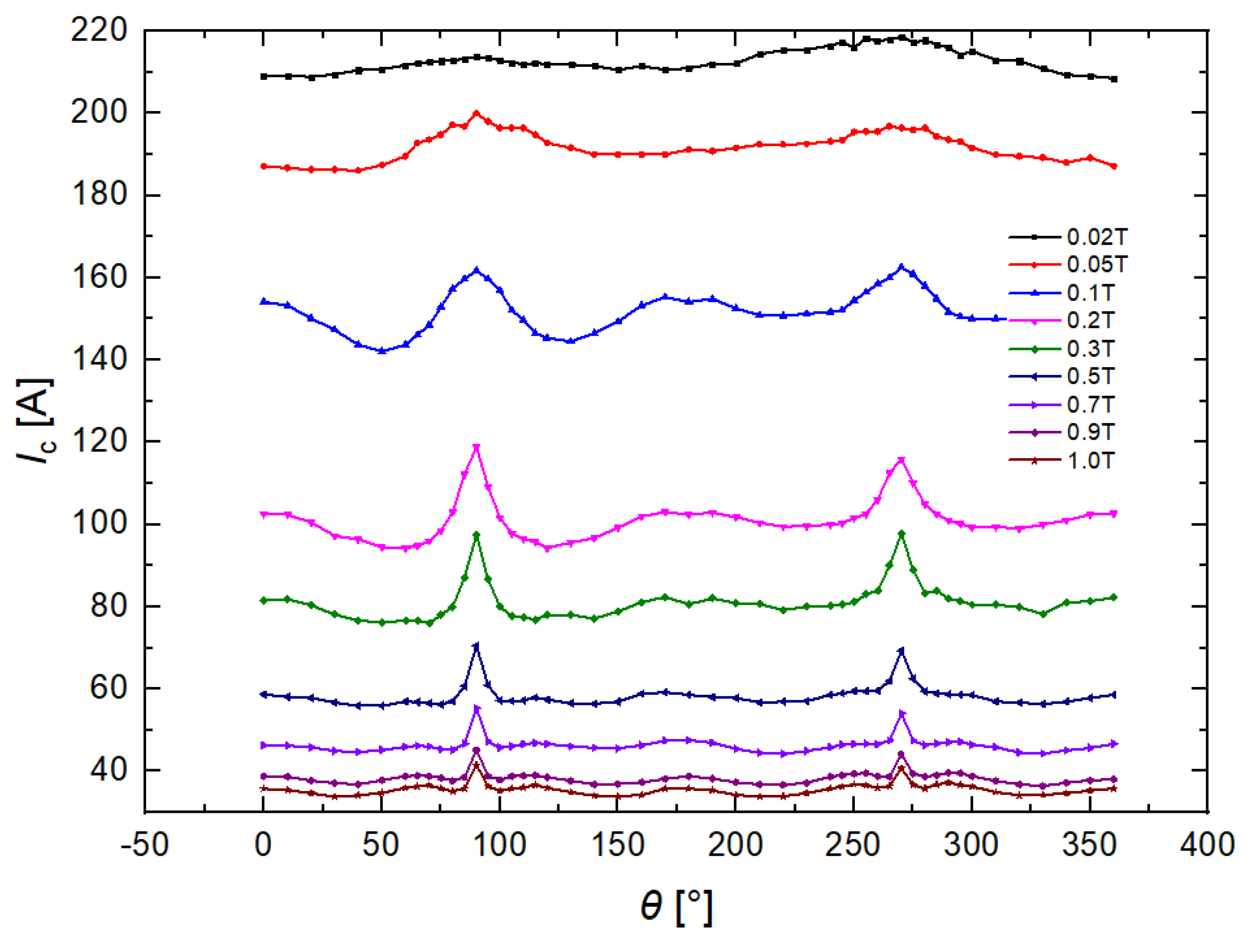
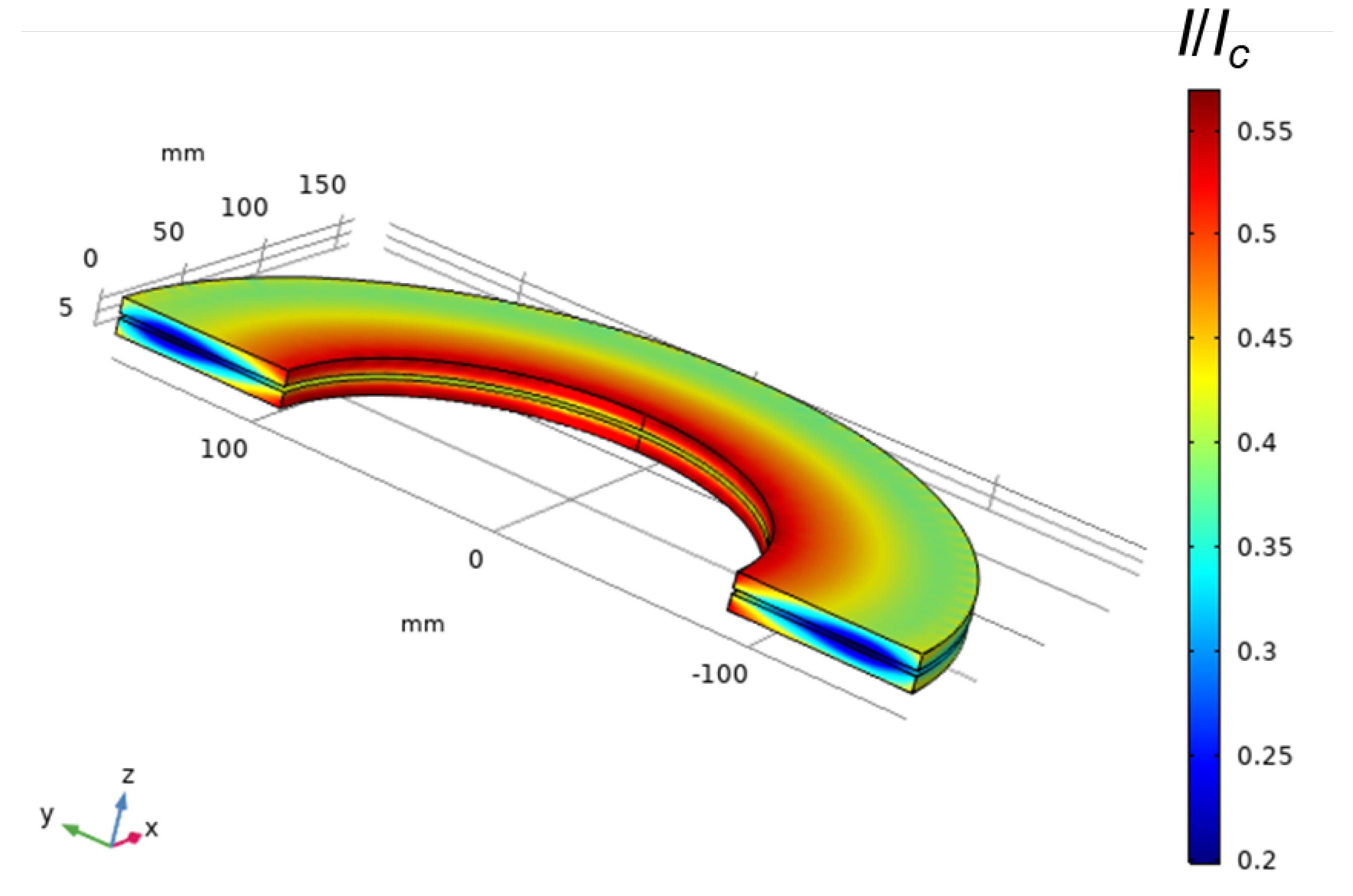
2.2. Load Factor Prediction and REBCO Tapes Selection
3. Fabrication and Experiment of the DP Module
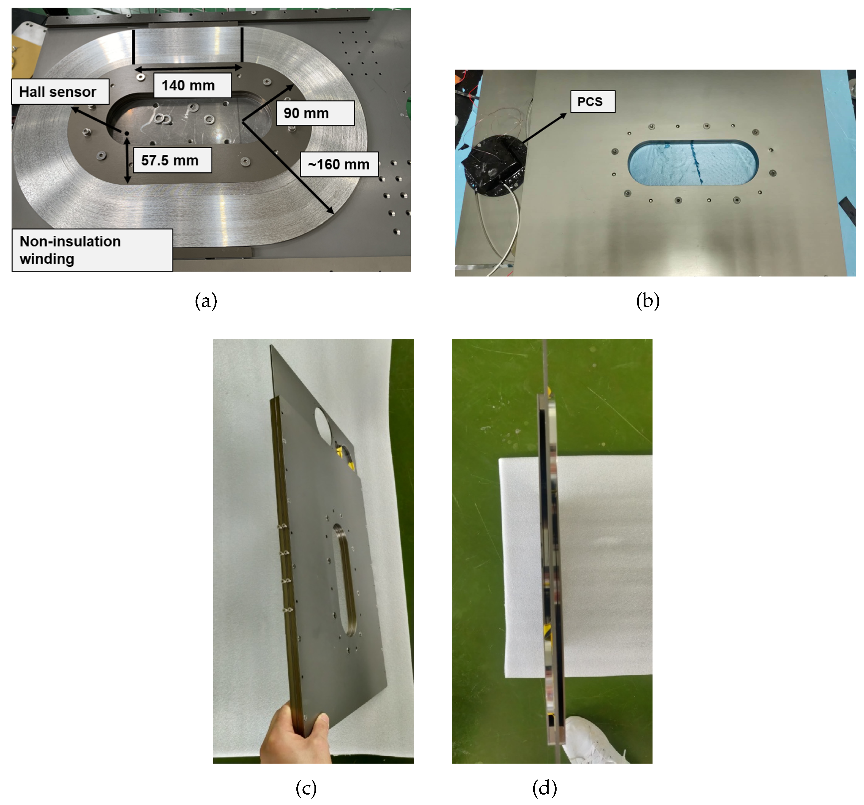
3.1. DP Module Fabrication
3.2. Excitation Experiments under Closed-Loop Condition
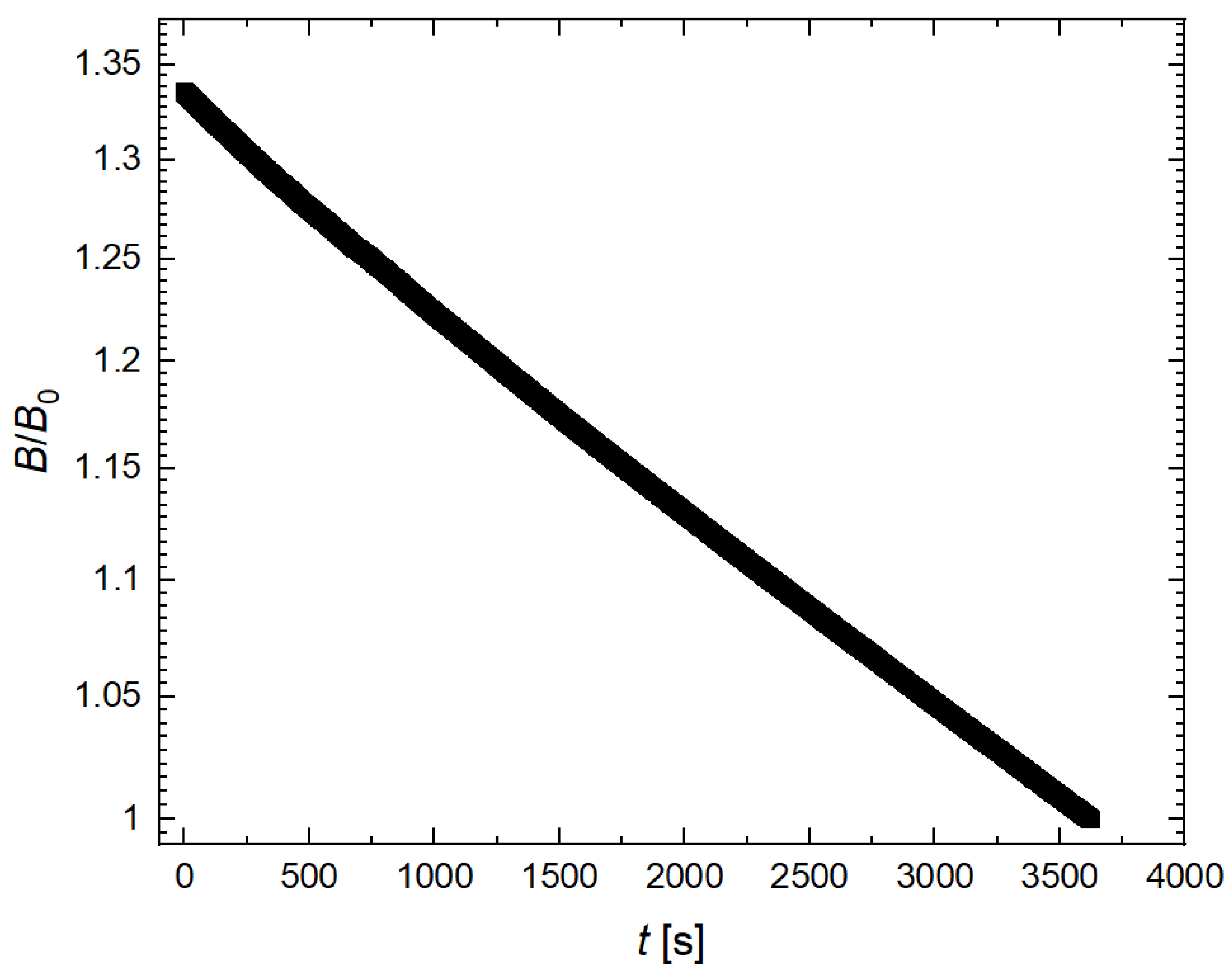
3.3. Persistent Current Mode
4. Conclusions
Author Contributions
Funding
Data Availability Statement
Conflicts of Interest
References
- Gong, T.; Ma, G.; Cai, Y.; Qian, H.; Li, J.; Deng, Y.; Zhao, Z. Calculation and Optimization of Propulsion Force of a Real-Scale REBCO Magnet for EDS Train. IEEE Trans. Appl. Supercond. 2019, 29. [Google Scholar] [CrossRef]
- Bernstein, P.; Noudem, J. Superconducting magnetic levitation: Principle, materials, physics and models. Supercond. Sci. Technol. 2020, 33, 033001. [Google Scholar] [CrossRef]
- Ding, J.F.; Yang, X.; Long, Z.Q.; Dang, N. Three-Dimensional Numerical Analysis and Optimization of Electromagnetic Suspension System for 200 km/h Maglev Train Considering Eddy Current Effect. IEEE Access 2018, 6, 61547–61555. [Google Scholar] [CrossRef]
- Abdelrahman, A.S.; Sayeed, J.; Youssef, M.Z. Hyperloop Transportation System: Analysis, Design, Control, and Implementation. IEEE Trans. Ind. Electron. 2018, 65, 7427–7436. [Google Scholar] [CrossRef]
- Safaei, F.; Suratgar, A.A.; Afshar, A.; Mirsalim, M. Characteristics Optimization of the Maglev Train Hybrid Suspension System Using Genetic Algorithm. IEEE Trans. Energy Convers. 2015, 30, 1163–1170. [Google Scholar] [CrossRef]
- Long, Z.Q.; He, G.; Xue, S. Study of EDS Halbach Array. IEEE Trans. Magn. 2011, 47, 4717–4724. [Google Scholar] [CrossRef]
- Nakao, H.; Yamashita, T.; Sanada, Y.; Yamaji, M.; Nakagaki, S.; Shudo, T.; Takahashi, M.; Miura, A.; Terai, M.; Igarashi, M.; et al. Development of a modified superconducting magnet for Maglev vehicles. IEEE Trans. Appl. Supercond. 1999, 9, 1000–1003. [Google Scholar] [CrossRef]
- Wang, W.; Lei, Y.; Huang, S.Q.; Wang, P.; Huang, Z.; Zhou, Q. Charging 2G HTS Double Pancake Coils With a Wireless Superconducting DC Power Supply for Persistent Current Operation. IEEE Trans. Appl. Supercond. 2018, 28. [Google Scholar] [CrossRef]
- Lee, S.; Kim, W.S.; Kim, Y.; Lee, J.Y.; Park, S.H.; Lee, J.K.; Hong, G.W.; Kim, S.; Han, J.; Hwang, Y.J.; et al. Persistent Current Mode Operation of A 2G HTS Coil With A Flux Pump. IEEE Trans. Appl. Supercond. 2016, 26. [Google Scholar] [CrossRef]
- Kang, L.; Xu, S.; Zhao, Z.W.; Sun, Z.Y.; Zhou, P.B.; Han, L.; Bai, L.Y.; Li, J.; Ma, G.T. Experimental Characterization of a No-Insulation HTS Racetrack Coil Subjected to Travelling Magnetic Fields. IEEE Trans. Appl. Supercond. 2020, 30. [Google Scholar] [CrossRef]
- Li, X.; Li, J.; Zhou, P.B.; Liu, K.; Han, L.; Song, X.L.; Ma, G.T. Decay of Trapped Magnetic Field in Stacks of YBCO Coated Conductors Subjected to Traveling Magnetic Waves. IEEE Trans. Appl. Supercond. 2019, 29. [Google Scholar] [CrossRef]
- Maeda, H.; Yanagisawa, Y. Recent Developments in High-Temperature Superconducting Magnet Technology (Review). IEEE Trans. Appl. Supercond. 2014, 24. [Google Scholar] [CrossRef]
- Mizuno, K.; Tanaka, M.; Ogata, M. Evaluation of eddy current heating in a REBCO magnet due to the magnetic field of ground coils for the maglev. Supercond. Sci. Technol. 2020, 33, 074009. [Google Scholar] [CrossRef]
- Mizuno, K.; Tanaka, M.; Ogata, M.; Okamura, T. Mechanical Vibration Test of a REBCO Coil Designed for Application to the Maglev. IEEE Trans. Appl. Supercond. 2018, 28. [Google Scholar] [CrossRef]
- Sugino, M.; Mizuno, K.; Tanaka, M.; Ogata, M. Development of a REBCO HTS magnet for Maglev-repeated bending tests of HTS pancake coils. Phys. C Supercond. Its Appl. 2018, 544, 13–17. [Google Scholar] [CrossRef]
- Mizuno, K.; Sugino, M.; Tanaka, M.; Ogata, M. Experimental Production of a Real-Scale REBCO Magnet Aimed at Its Application to Maglev. IEEE Trans. Appl. Supercond. 2017, 27. [Google Scholar] [CrossRef]
- Wang, Y.; Chan, W.K.; Schwartz, J. Self-protection mechanisms in no-insulation (RE) Ba2Cu3Ox high temperature superconductor pancake coils. Supercond. Sci. Technol. 2016, 29, 045007. [Google Scholar] [CrossRef]
- Iwasa, Y. Case Studies in Superconducting Magnets; Springer: New York, NY, USA, 2009. [Google Scholar]
- Hao, L.; Huang, Z.; Dong, F.; Qiu, D.; Shen, B.; Jin, Z. Study on Electrodynamic Suspension System with High-Temperature Superconducting Magnets for a High-Speed Maglev Train. IEEE Trans. Appl. Supercond. 2019, 29. [Google Scholar] [CrossRef]
- Ling, J.; Voccio, J.P.; Hahn, S.; Kim, Y.; Song, J.; Bascunan, J.; Iwasa, Y. Construction and Persistent-Mode Operation of MgB2 Coils in the Range 10-15 K for a 0.5-T/240-mm Cold Bore MRI Magnet. IEEE Trans. Appl. Supercond. 2015, 25. [Google Scholar] [CrossRef]
- Noguchi, S. Electromagnetic, Thermal, and Mechanical Quench Simulation of NI REBCO Pancake Coils for High Magnetic Field Generation. IEEE Trans. Appl. Supercond. 2019, 29. [Google Scholar] [CrossRef]
- Pan, Y.; Wu, W.; Sheng, J.; Li, X.; Dong, F.; Wang, M.; Zhao, Y.; Zhang, Z.; Li, Z.; Huang, Z.; et al. An equivalent homogenized model for non-superconducting joints made by ReBCO coated conductors. Supercond. Sci. Technol. 2018, 31. [Google Scholar] [CrossRef]


| Parameters | Values |
|---|---|
| Magnetic momentum of a single pole | ⩾360 kA |
| Axial magnetic flux at the central line 90-mm | |
| from the HTS coils module’s bottom surface | ⩾0.7 T |
| Axial magnetic flux at the central line of the | |
| figure-eight-shaped coils’ surface | ⩾0.9 T |
| Decay rate | ⩽1%/day |
| Poles | 8 (4 for each side) |
| Number of DP modules for a single pole | 3 |
| Turns of a DP module | 600 |
| Operation current | 200 A |
| Single-pole dimensions (Central line) | 390 mm · 250 mm · 66 mm |
| Spital distance of the poles | 540 mm |
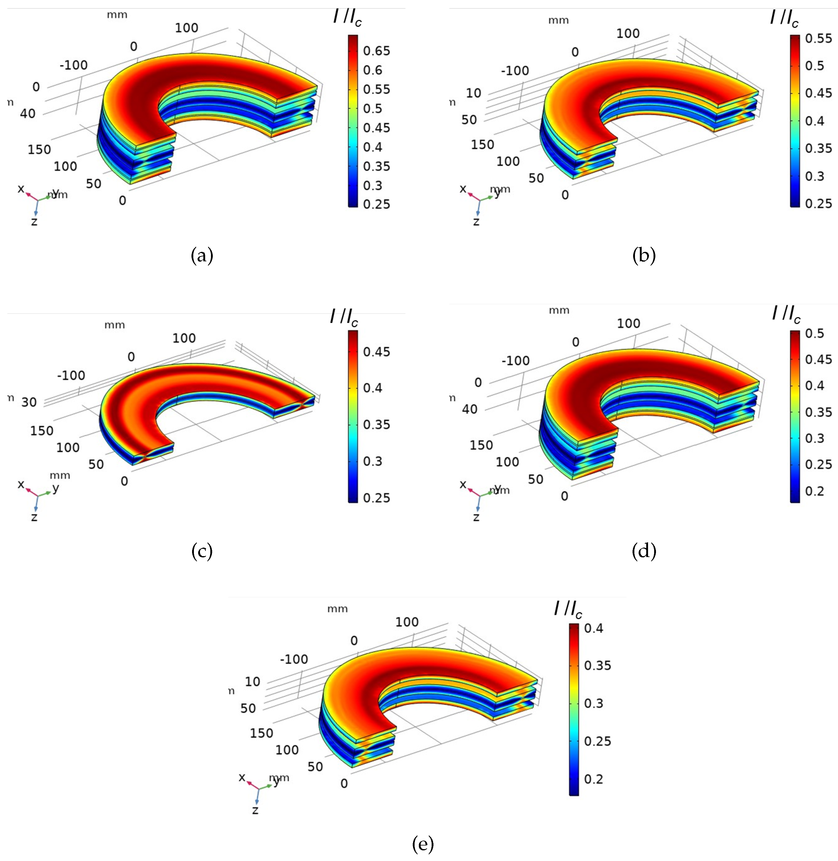
| Location and Segment | Turns: 201–300 | Turns: 101–200 | Turns: 1–100 |
|---|---|---|---|
| The two outside pancakes (tape A) | 0.47 | 0.51 | 0.51 |
| The two middle pancakes (tape A) | 0.36 | 0.39 | 0.41 |
| The two central pancakes (tape B) | 0.43 | 0.45 | 0.46 |
| Parameters | Values |
|---|---|
| Turns | 290 and 293 for each single pancake |
| Inductance | ∼160 mH |
| Encapsulation layer thickness | 75 m copper for each side |
| Tape width/thickness | 5.75 mm/0.24 mm |
| REBCO layer width | 4.75 mm |
| Equivalent turn-to-turn resistivity | 1.3 μΩ· |
Publisher’s Note: MDPI stays neutral with regard to jurisdictional claims in published maps and institutional affiliations. |
© 2021 by the authors. Licensee MDPI, Basel, Switzerland. This article is an open access article distributed under the terms and conditions of the Creative Commons Attribution (CC BY) license (https://creativecommons.org/licenses/by/4.0/).
Share and Cite
Lu, L.; Wu, W.; Yu, X.; Jin, Z. High-Temperature Superconducting Non-Insulation Closed-Loop Coils for Electro-Dynamic Suspension System. Electronics 2021, 10, 1980. https://doi.org/10.3390/electronics10161980
Lu L, Wu W, Yu X, Jin Z. High-Temperature Superconducting Non-Insulation Closed-Loop Coils for Electro-Dynamic Suspension System. Electronics. 2021; 10(16):1980. https://doi.org/10.3390/electronics10161980
Chicago/Turabian StyleLu, Li, Wei Wu, Xin Yu, and Zhijian Jin. 2021. "High-Temperature Superconducting Non-Insulation Closed-Loop Coils for Electro-Dynamic Suspension System" Electronics 10, no. 16: 1980. https://doi.org/10.3390/electronics10161980