Article

Transmission Analysis in Human Body Communication for Head-Mounted Wearable Devices

1
Research Institute for Science and Technology, Organization for Research Advancement, Tokyo University of Science, 2641 Yamazaki, Noda, Chiba 278-8510, Japan
2
Department of Human and Engineered Environmental Studies, Graduate School of Frontier Sciences, The University of Tokyo, 5-1-5 Kashiwanoha, Kashiwa, Chiba 277-8563, Japan
*
Author to whom correspondence should be addressed.
Electronics 2021, 10(10), 1213; https://doi.org/10.3390/electronics10101213
Submission received: 15 April 2021 / Revised: 13 May 2021 / Accepted: 18 May 2021 / Published: 19 May 2021
(This article belongs to the Special Issue Antennas for Wearable and Implantable Applications)

Abstract

:
As society ages, wireless body area networks (WBANs) are expected to increasingly improve the quality of life of the elderly and disabled. One promising WBAN technology is human body communication (HBC), which utilizes part of the human body as a transmission medium. Communication between head-mounted wearable devices, such as hearing aids, is a potential HBC application. To clarify the HBC transmission mechanism between head-mounted wearable devices, this study analyzes the input impedance characteristics of the transceiver electrodes, transmission characteristics, and electric field distributions around and through a detailed head model. The investigation was performed via an electromagnetic field simulation. The signal frequency had less effect on the transmission characteristics and electric field distributions at 10, 20, and 30 MHz. However, the transmission mechanism between the head-mounted wearable devices was influenced by the number of electrodes in the transceiver. Moreover, the transmission characteristics between two-electrode transceivers were improved by impedance matching. Finally, the availability of the proposed system was evaluated from power consumption and human safety perspectives.

1. Introduction

Driven by recent advances in high-density integration technology, information communication devices have evolved from “mobile” to “wearable”. The next-generation multiple wearable devices are expected to be connectable through a wireless body area network (WBAN), which is defined as a network of devices in close proximity to a person’s body [1]. In 2012, the IEEE 802.15.6 working group standardized WBAN [2]. WBANs are primarily applied in medical and welfare devices, which must be connected for the exchange of data such as vital signs data. As society ages, the role of these technologies is expected to increase for improving the quality of life of the elderly and disabled. Many of these devices adopt short-range wireless communication standards (within a few meters around the body). Examples of the commonly used standards are Bluetooth Low Energy and ZigBee (both operate at 2.4 GHz). In Japan, an extremely low-power radio system, which operates in the 315 MHz band, and a specified low-power radio system, which operates in the 400 MHz band [3,4], are also popular. Usually, the human body is regarded as an obstacle in wireless communication because the human body absorbs high-frequency electromagnetic waves in the 315 MHz to 2.4 GHz range [5,6].
Human body communication (HBC), which utilizes a part of the human body as a transmission medium, has attracted considerable attention as one of the methods for WBAN data transmission [7]. In HBC, a radio-frequency signal flowing through the body and in the near-field electric field or in a surrounding quasi-electrostatic field contributes to the communication among devices [8]. Meanwhile, the human body is a conductive dielectric medium [9]; therefore, if the electrodes induce a high-frequency signal in the body’s interior, a current path is formed on the body’s surface. Furthermore, frequencies under several tens of megahertz produce a near-field electric field at the interface between the body and space (air) that dominates over the far-radiated electromagnetic field [10,11]. As near-field electric fields tend to exponentially diminish with distance, there is little leakage of the electromagnetic field into the surrounding space during transmission, enabling communication with excellent confidentiality and no electromagnetic noise generation. The limited communication distance can potentially reduce communication power consumption compared with that of existing wireless communication technology, which uses airborne electromagnetic waves. Two types of HBC are recognized: galvanic and capacitive coupling [12]. In galvanic coupling HBC, the signals of both the electrode and ground electrode of the transceivers are in contact with the body [13]. By contrast, in capacitive coupling HBC, the body is in contact with the signal electrode alone, and the ground electrode is floating [14,15,16,17]. In both types of HBC, transmission is contributed by the current flowing through the human body and the electric field around the human body, but the exact modeling of transmission remains problematic. To clarify the transmission mechanism of HBC and optimize the physical layer components, such as the carrier frequency and impedance of the frontend circuit, researchers have developed different types of models [18,19,20,21].
Although many HBC systems have been proposed [22,23,24,25,26,27,28,29,30,31,32,33,34,35], the devices were mainly worn on arms and trunks. To widen the range of applications, we previously investigated the basic transmission mechanism of HBC between head-mounted wearable devices [36]. In the present study, we further clarified the HBC transmission mechanism by investigating various signal transmission parameters in numerical simulations. For this purpose, we adopted the finite difference time domain (FDTD) method because this full-wave approach can be used to calculate the detailed electric field distributions within and around human head tissue.
The remainder of this paper is organized as follows. Section 2 proposes our HBC system between head-mounted wearable devices (assumed as hearing aids) and explains the system specifications, such as the device position and carrier frequencies. Section 3 illustrates the simulation setup (a human body and transceiver models) for analyzing the signal transmission parameters of the proposed HBC system. In Section 4, the 2.45 GHz WC and HBC are compared considering the effects of the human body. Next, the best human model is determined in terms of the trade-off between computer resources and accuracy of the calculation results. Subsequently, we calculate the input impedance characteristics of the transceiver electrodes, the transmission characteristics between transceivers, and electric field distributions around/inside the head, and hence clarify the transmission mechanism of the proposed system. To improve the transmission characteristics, we investigated the impedance matching at the feeding point and the transceiver load, and we evaluated the power consumption and human safety of our system. Conclusions are drawn in Section 5.

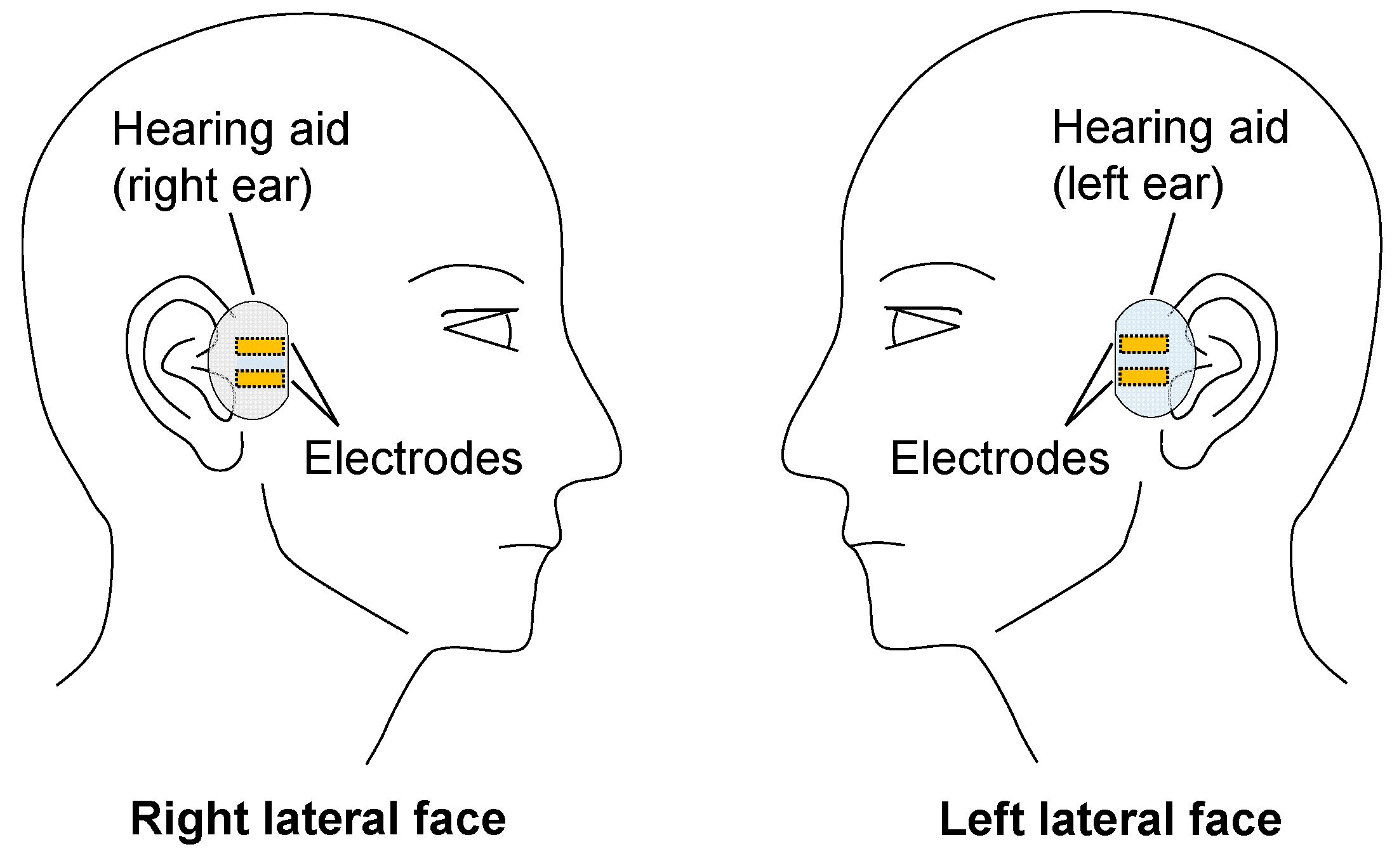
2. Proposed HBC System

Nearly 90% of hearing-impaired people suffer from binaural hearing loss [37,38] and prefer the simultaneous use of hearing aids in both ears [39]. When installed in both ears, hearing aids also help in localizing the sound source and improve hearing in noisy environments [40]. Both hearing aids must communicate in real time and optimize the sounds in a given situation. Mobile computing platforms [41] have improved the user experience and usability of binaural hearing aid systems. In most cases, the hearing aids in each ear communicate through a 2.45 GHz wireless communication (2.45 GHz WC) system [42,43,44]. However, as the communication signals are 2.45 GHz electromagnetic waves, they are significantly absorbed by the biological tissues of the head [45]. This phenomenon occasionally causes communication blackouts between the two ear-mounted devices.
In this study, we investigated HBC between two head-mounted wearable devices, considering communication between two hearing aids. Figure 1 shows the proposed HBC system. The wearable devices’ electrodes are assumed to be attached directly to the skin. As the carrier frequencies, we selected 10, 20, and 30 MHz because the transmission efficiency peaked frequency range including these frequencies in previous studies [46], and because our assumed usages are the industry–science–medical (ISM) band (13.56 MHz) [47] and the IEEE 802.15.6 standard (21 and 32 MHz bands) [2]. This standard provides a Media Access Control layer supporting high-reliable and low-latency communication for medical and welfare systems. Therefore, HBC can be used for communication between hearing aids from the viewpoint of data transmission protocol.

3. Simulation Models

In this study, we assumed signal transmission between two wearable transceivers worn on each side of the head. For comparison, we also analyzed conventional wireless communications at 2.45 GHz. Analyses were performed using the simulation software XFdtd (Remcom Inc., State College, PA, USA), which employs the FDTD method.

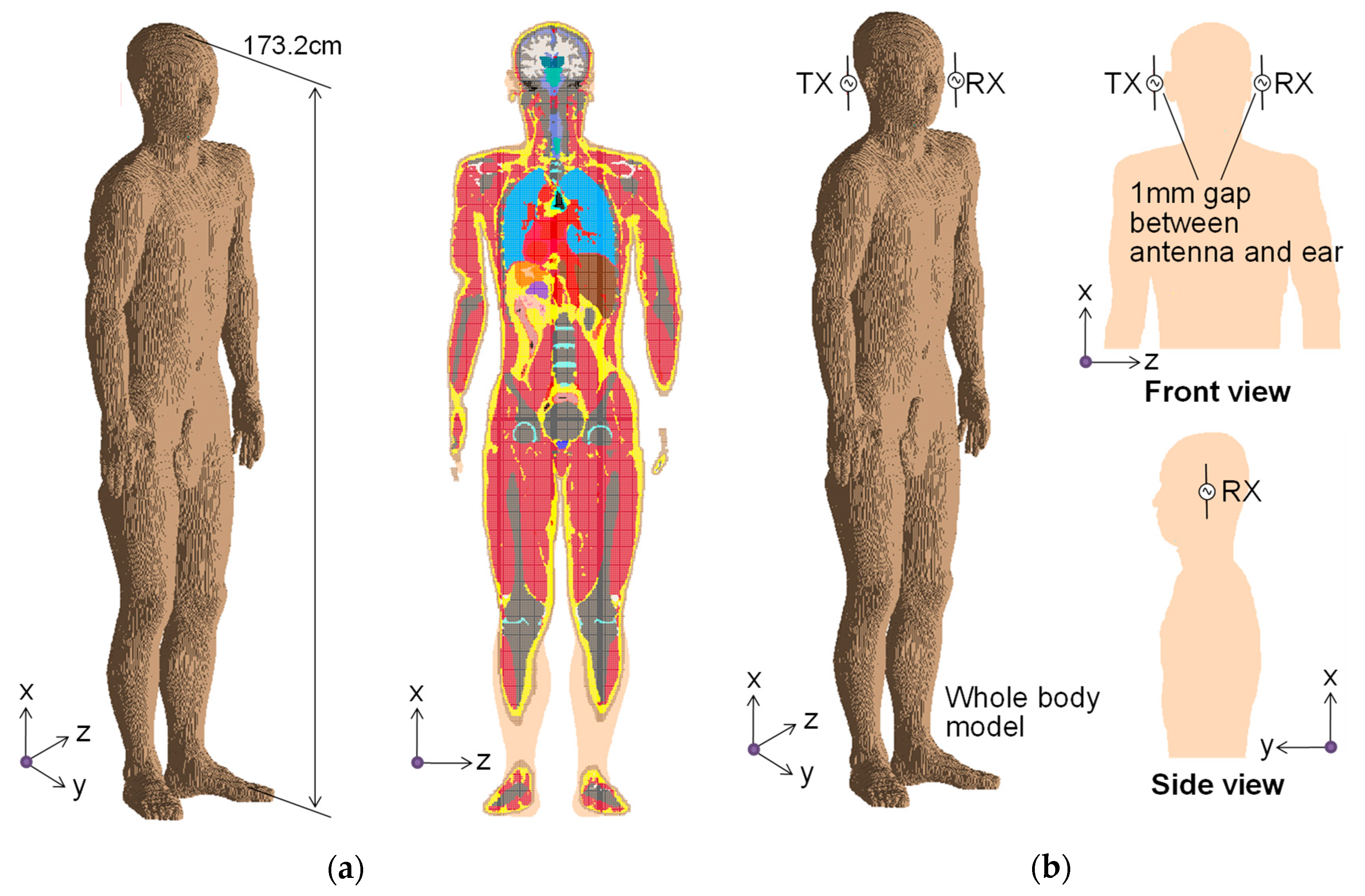
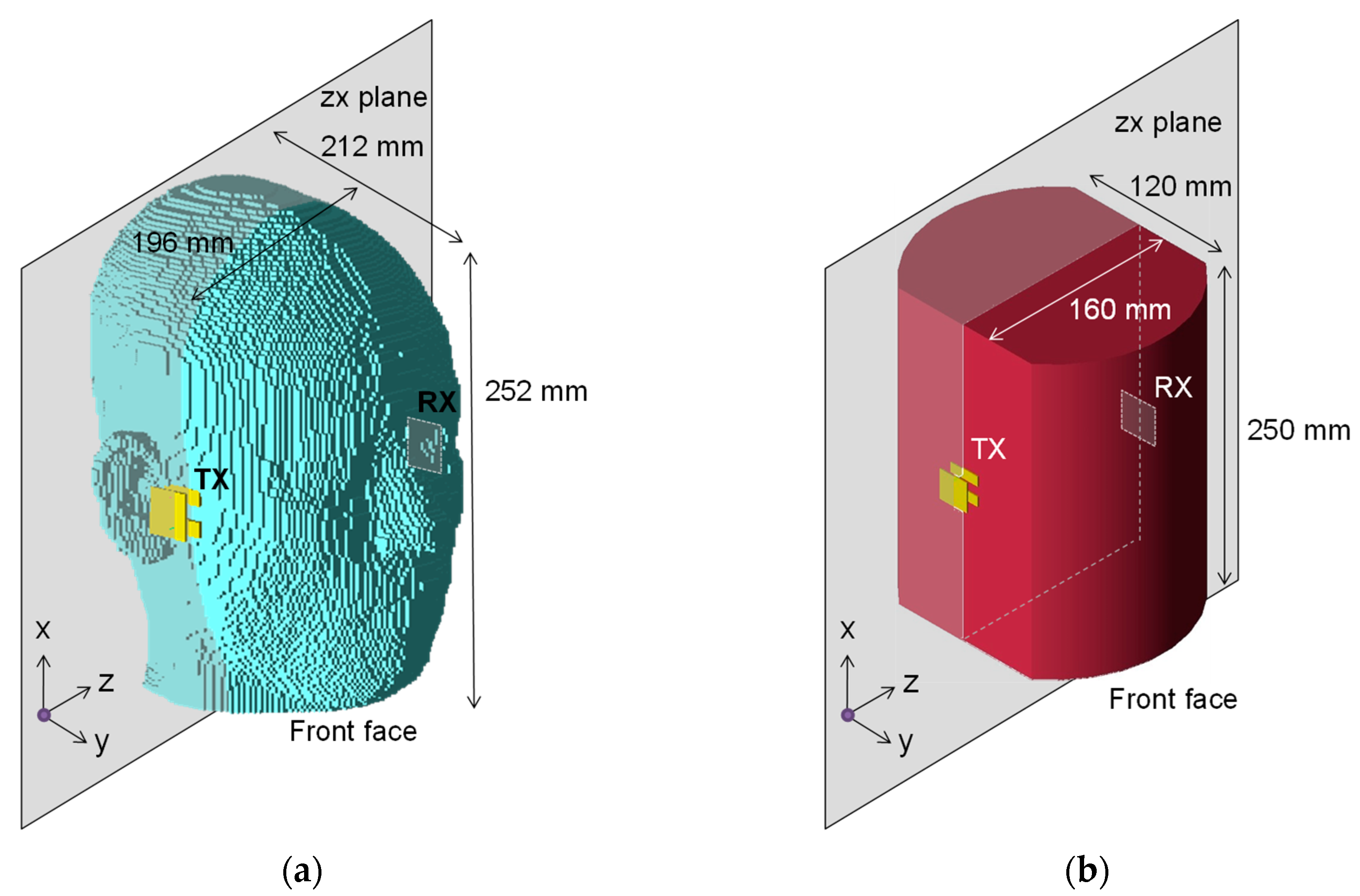
3.1. Human Body Models

To evaluate the trade-off between calculation accuracy and time, we simulated three types of human body models with different simplifications. Figure 2 shows the whole-body human model “TARO” provided by the National Institute of Information and Communications Technology [48]. Panel (a) of this figure shows the model dimensions and a cross-sectional view in the x-z plane, and (b) shows the positions of the transceiver antennas in the 2.45-GHz WC simulation. This model is useful for calculating signal propagations because it comprises 51 different biological tissues (including skin, fat, and muscle), each with its own electrical properties. In this study, the electrical property of each biological tissue was assumed to be frequency-dependent [9].
Figure 3a shows the detailed human head model extracted from the whole-body model “TARO”. This head model, which consists of 23 biological tissues, reduces the memory requirements, CPU/GPU power, and calculation time because the trunk is removed. The head model in Figure 3b is further simplified by assuming homogenous muscle tissue. The homogenous muscle model is popular because it is the simplest model for the qualitative analysis of WBAN, including HBC [22,49]. In addition, we compared the results of a homogenous muscle arm model and a three-layered arm model composed of skin, fat, and muscle. The patterns of electric field distribution were similar in both models, but some quantitative values differed between the models [50]. To reduce the edge effect of the electric field, the front and back surfaces of the model were curved into a shape resembling the actual head shape. Both temporal regions of the model were flattened for perfect attachment of the electrodes. The model dimensions were based on the average body shape of a Japanese adult [51]. The model composed only of muscle tissues was also given a frequency-dependent electrical property.

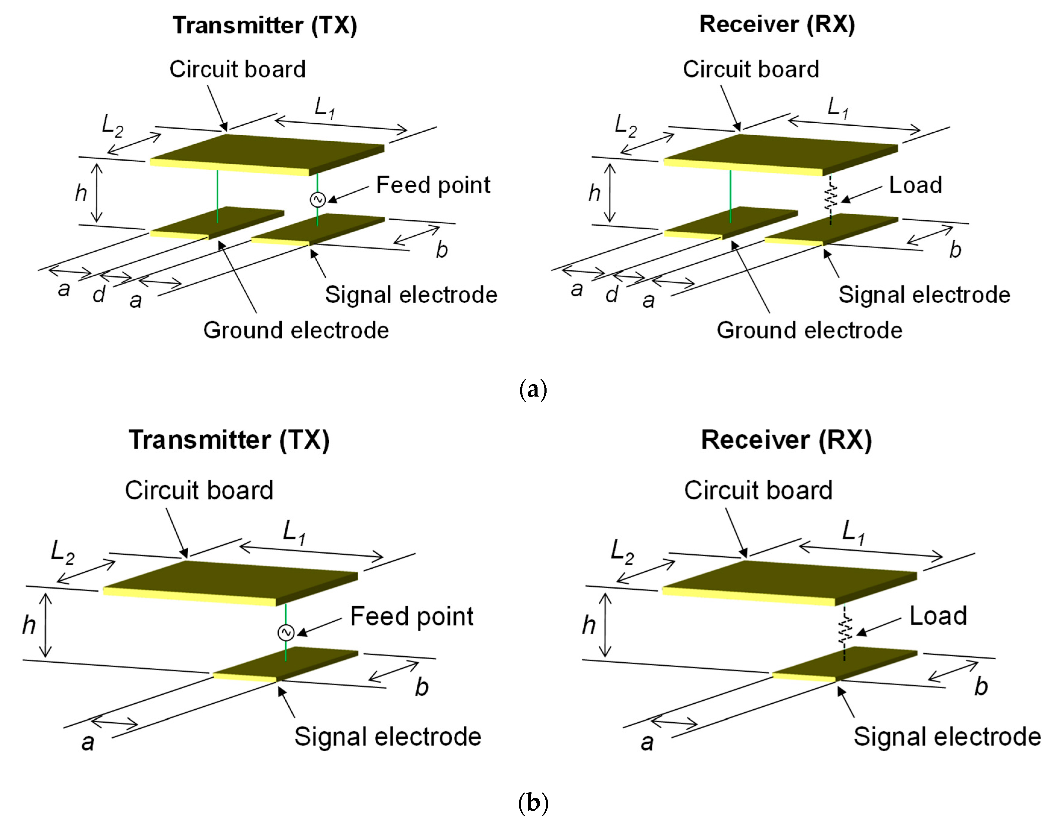
3.2. Transceiver Electrode and Antenna Models

Figure 4 shows the structures of the transceivers (transmitter: TX, receiver: RX) in the electrode model of the HBC simulation. One transceiver was located at each temple. In this figure, panel (a) presents the two-electrode model and panel (b) presents single-electrode models. The two-electrode model comprises a circuit board, a signal electrode, a ground electrode, wires, and a feeding point (transmitter) with an output impedance of 50 Ω or a passive load (receiver) with a 50 Ω resistance. We adopted the transmitter and receiver designed in our previous studies (a = 8, b = 24, d = 8, L1 = 24, L2 = 24, and h = 10 mm). The electrodes of these devices were designed to provide input and output impedances of 50 Ω in a muscle homogenous model [52]. The single-electrode model consisted of a circuit board, a signal electrode, wires, and a feeding point (transmitter) with an output impedance of 50 Ω or a passive load (receiver) with a 9 kΩ resistance. All transceivers were composed of a perfect electric conductor (PEC) material. The undersurfaces of the electrodes were designed for firm attachment to the skin when applied to the detailed head model.
As the transceiver antenna of the 2.45 GHz WC, we employed a dipole antenna adjusted to resonate at 2.45 GHz in free space. The antenna was constructed from a PEC–wire element with a length of 54 mm. A feeding point (transmitter) with 50 Ω output impedance or a 50 Ω resistance passive load (receiver) was placed at the center of the antenna element.

3.3. Simulation Conditions

The computing space of the FDTD simulation was represented by non-uniform grids. As the grids became more distant from the vicinity of the transceiver electrodes and antennas, their size gradually increased. The grid size was 1 mm around the transceiver electrodes and 5 mm at the edge of the computing space. The padding, or free-space distance between the model edge and absorbing boundary, was 20 cells thick. The absorbing boundary was a perfectly matched layer composed of seven sublayers in the two-electrode and 2.45 GHz antenna transceiver models, and 15 layers in the single-electrode transceiver model. A lumped port was selected as both the feeding point and receiving load of the transceivers. A broadband pulse was fed at the feeding point. The time steps of the HBC and 2.45 GHz WC calculations were set to 1.872 and 1.048 ps, respectively.

4. Results and Discussion

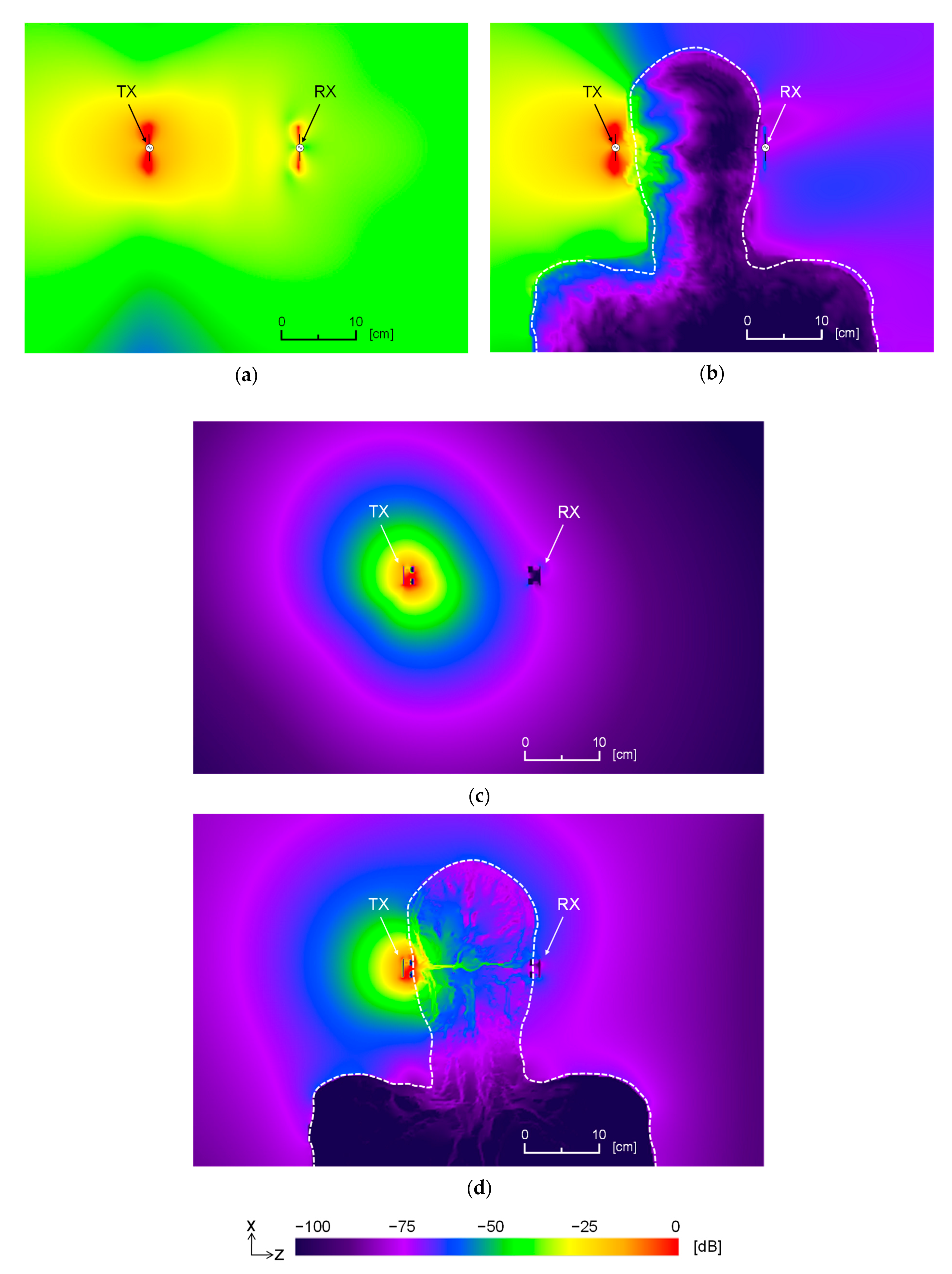
4.1. Effects of Human Body on Signal Transmission

This subsection examines the effects of the human body on communications between the head-mounted wearable devices in the whole-body human model (Figure 2). The 2.45 GHz WC and HBC were analyzed in two environments: one with the human body (LOS) and the other without the human body (NLOS). In the 2.45 GHz WC simulation, the impedances of the feeding point and receiving load of the transceiver antennas were both set to 50 Ω. In the HBC simulation, the electrode configuration was a two-electrode transceiver, and the carrier frequency was 10 MHz. The impedances of the feeding point and receiving load of the transceiver electrodes were both set to 50 Ω.
Panels (a)–(d) of Figure 5 show the electric field distributions calculated under each condition, and Table 1(a)–(d) lists the transmission characteristics S21 between the transceivers under the conditions of Figure 5. The electric field distribution was observed in the x-z plane, which included the feeding point, as shown in Figure 3. The dotted curve in Figure 5 outlines the boundary between the human body model and free space. As shown in Figure 5a,b, the electric field was blocked by the human body between the transceiver antennas, and the signal in the 2.45 GHz WC was not propagated. The human body deteriorated the S21 by 50 dB or more (Table 1(a),(b)). From these results, we inferred that the 2.45 GHz WC is unsuitable in the NLOS environment caused by the human body such as the communication between head-mounted wearable devices. In contrast, the electric field was propagated through the head in the HBC scenario (Figure 5c,d), and the head tissues improved the S21 by 46 dB (Table 1(c),(d)). On the contrary, the electric field was attenuated by > 50 dB in the free space at 10 cm from the feeding point. As a result of this exponential decrease in the electric field, the signal propagated along the body without interfering with other devices. This feature is beneficial for confidential communication and EMC. In the NLOS environment, the S21 was approximately 10 dB larger in the HBC scenario than in the 2.45 GHz WC scenario. Furthermore, as shown in Section 4.4, S21 can be further improved by impedance matching. These results demonstrate that the proposed system achieves stable communication and that HBC reduces the power consumption.

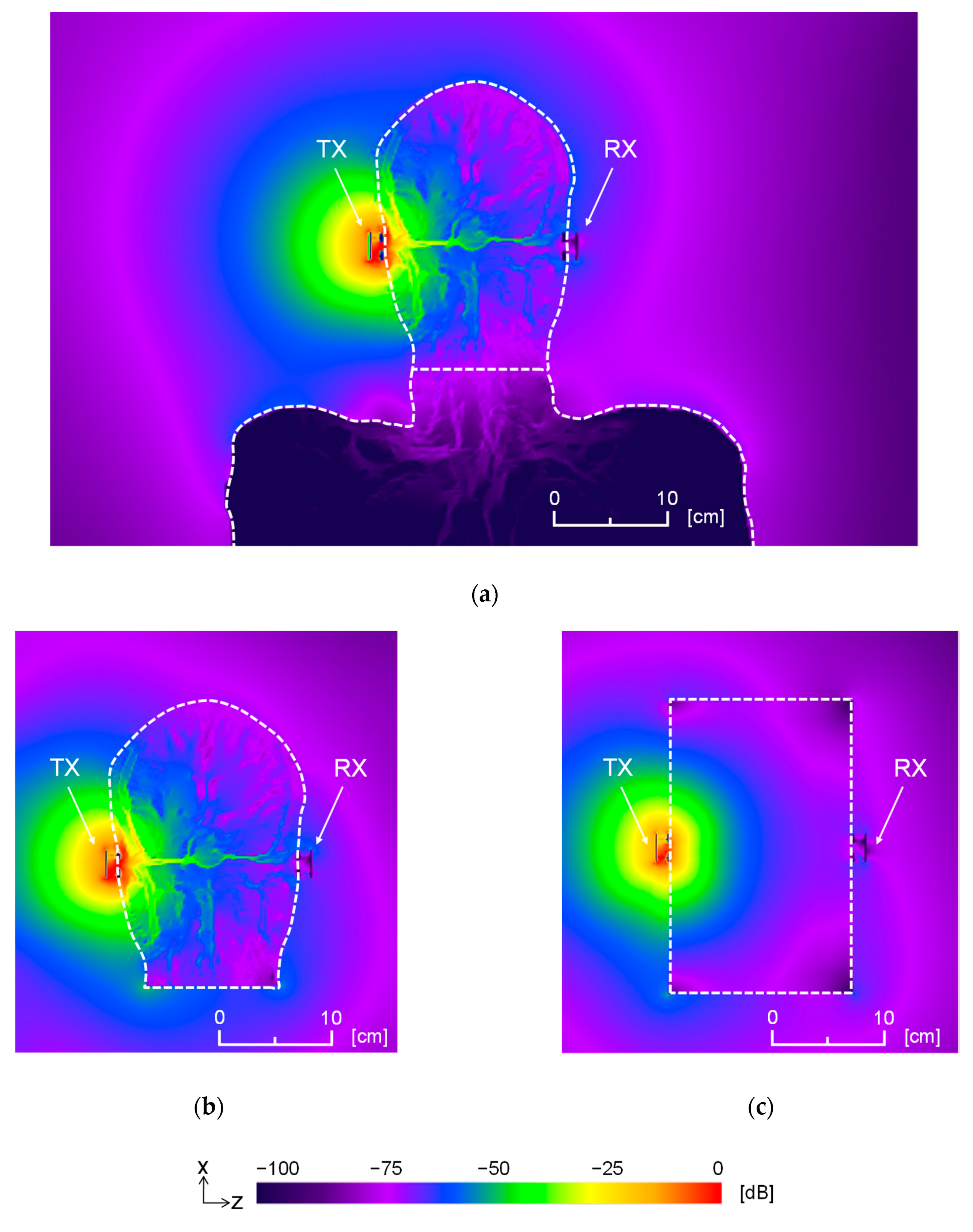
4.2. Simplification of Human Body Model

To properly meet the trade-off between the computer resources and the accuracy of the calculation results, the model should be simplified but without significantly affecting the calculated transmission characteristics and electric field distributions. The model shown in Figure 3a is the detailed human head model extracted from the whole-body model. Since it removes the other parts, this model significantly conserves the computer resources. However, as the trunk and limbs may affect the distribution and transmission characteristics of the electromagnetic field, this model must be confirmed. As mentioned earlier, the model in Figure 3b is further simplified to a simple solid with homogenous muscle, which conserves more computer resources than the detailed head model. However, the different electrical properties of the different biological tissues may greatly influence the transmission parameters of HBC. Therefore, the homogenous head model without tissue structure must also be validated. In the present study, the simplified models were validated using a two-electrode transceiver and a 10-MHz carrier frequency. The impedance of the feeding point and receiving load of the transceiver electrodes were both set to 50 Ω.
Figure 6 shows the electric field distribution calculated under each condition. Again, the electric field distribution was observed on the x-z plane, which includes the feeding point, and the white dotted curve delineates the boundary between the human body model and free space. Table 2 lists the resistive and imaginary components, Re(Zin) and Im(Zin), respectively, of the input impedances of the electrodes. It also lists the transmission characteristics S21 between the transceivers. Comparing panels (a) and (b) of Figure 6, we observe that the electric field distributions around and inside the head were almost identical in the whole-body and detailed head models, for the following reasons. At a carrier frequency of 10 MHz, the wavelength is 30 m, which is sufficiently larger than the total length of the human body, and the electric field distribution was determined by the local conditions i.e., the head. Furthermore, as shown in Table 2(a),(b), all transmission parameters were almost unaffected by the body parts below the neck.
In contrast, comparing Figure 6b,c, the electric field distribution was significantly altered in the head model with simplified shape and tissue structure. Zin was also changed significantly, and S21 increased by more than 1 dB (Table 2(b),(c)). As evidenced in the different electric field distributions, the signal transmission in HBC was enabled by the complicated distribution of biological tissues with their different electrical properties. A similar investigation performed at 20 and 30 MHz confirmed that when analyzing the transmission parameters of HBC, the body parts below the neck could be ignored, but the tissue structure was important. Overall, the detailed head model shown in Figure 3a was considered as the best model considering the trade-off between the resource demands and accuracy of the computational results. Therefore, the detailed head model was used in subsequent studies.

4.3. Transceiver Electrodes Configuration and Carrier Frequency in HBC

In communications between wearable devices worn on the body other than the head, a two- or single-electrode transceiver is employed to improve the transmission efficiency in a given situation. However, the transmission mechanism can differ when wearable devices are worn on both sides of the head from that when worn on the arm because the transmitter and receiver are at separate locations on the human body. The two-electrode and single-electrode models, as shown in Figure 4a,b, respectively, have been proposed as transmitter structures. Considering their HBC-coupling mechanisms, the two-electrode and single-electrode models are classified as galvanic and capacitive coupling HBC models, respectively. In this subsection, we clarify the transmission mechanisms for different numbers of contact electrodes, input impedance characteristics of the transceiver electrodes Zin, transmission characteristics S21, and electric field distributions around/inside the detailed head model. Moreover, the carrier frequency was varied as 10, 20, and 30 MHz focusing on the physical layer defined in ISM band, IEEE 802.15.6.

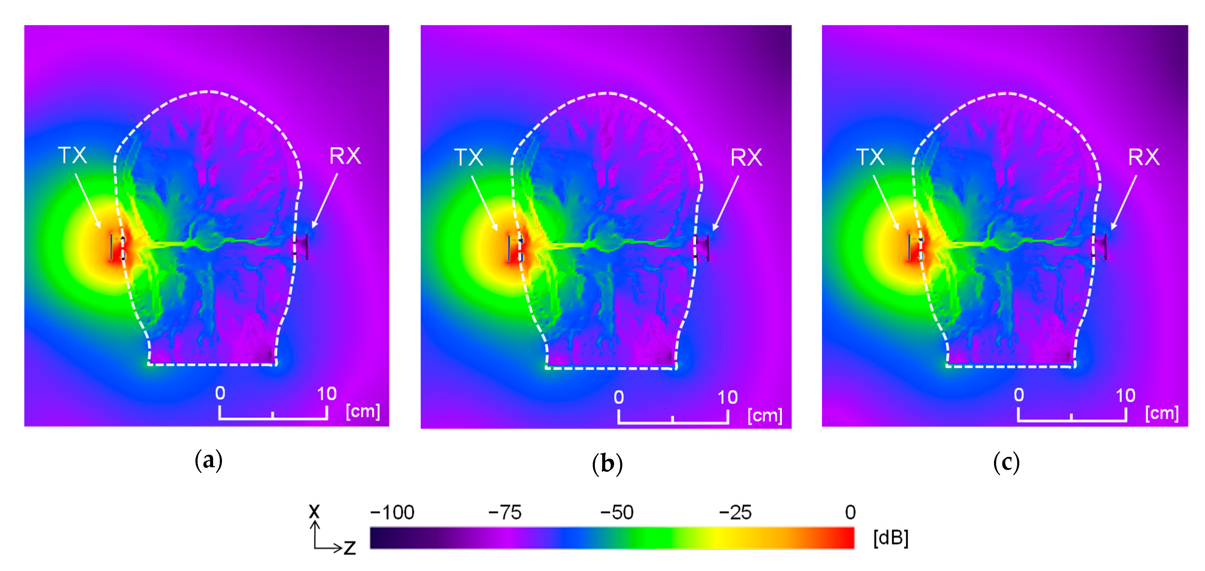
4.3.1. Two-Electrode Transceiver

Figure 7a–c shows the electric field distributions around and inside the human head in the x-z plane, including the feeding point of the transceiver. The Re (Zin) and Im (Zin) impedance components decreased with increasing carrier frequency (Table 3), and S21 ranged from −64.3 to −64.8 dB. Signal frequencies of 10, 20, and 30 MHz negligibly affected the transmission characteristics and electric field distributions, implying that the transmission characteristics are stable in the 10–30 MHz range. Therefore, we can select the carrier frequency that best fits the available frequency bands, avoids interference from other wireless systems, and satisfies the hardware restriction. Furthermore, the electric field generated by the two-electrode transceiver penetrated the head interior because the high-frequency current was concentrated between the signal and ground electrodes. The penetrating electric field had a significant effect on the transmission. This transmission mechanism of a two-electrode transceiver is quite different from that of 2.45 GHz WC. The improved transmission characteristics of our system are promising for future development; however, the system must first be evaluated from a human safety viewpoint.

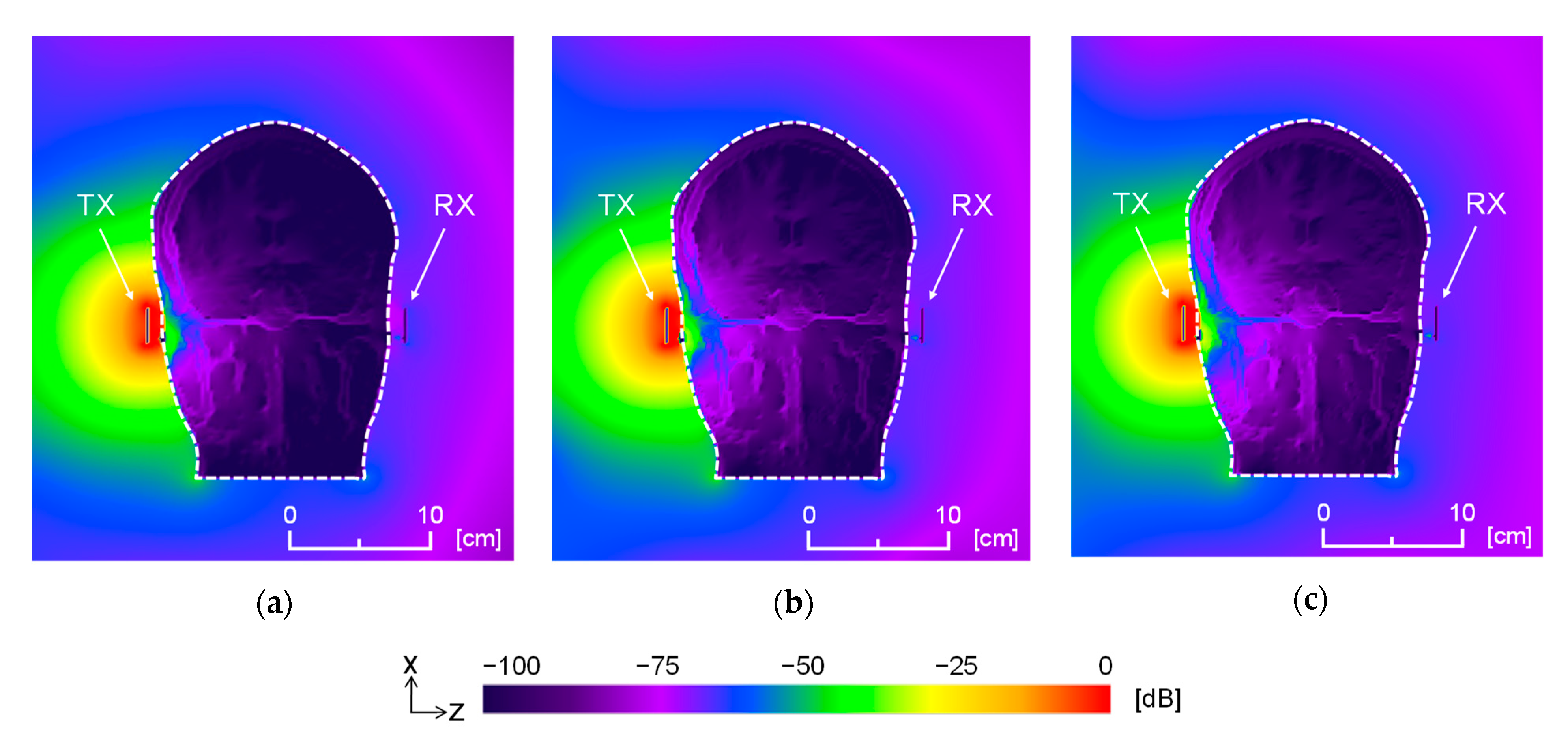
4.3.2. Single-Electrode Transceiver

Figure 8a–c show the electric field distributions around and inside the human head in the x-z plane, including the feeding point of the transceiver. As shown in Table 4, the signal frequencies at 10, 20, and 30 MHz had a negligible effect on the S21 and electric field distributions but a significant effect on the Im(Zin) because the imaginary impedance includes the capacitive reactance (determined by the floating capacitance between the circuit board and the human body), which depends on the carrier frequency. The electric field of the single-electrode transceiver moved around the head without penetrating it (Figure 8). This transmission mechanism was similar to that of 2.45 GHz WC, implying that the electric current in the biological tissues was small. Although this finding is favorable from a human safety viewpoint, the transmission characteristics were degraded.

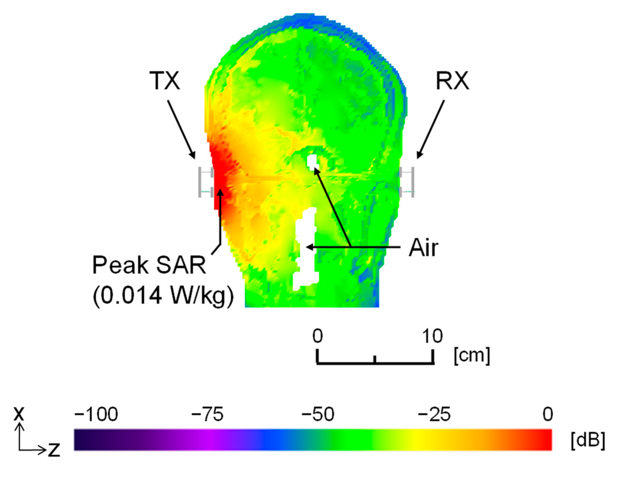
4.4. S21 Improvement by Impedance Matching and Exposure Assessment for Human Safety

In Section 4.3, it was suggested that the transmission characteristics of the two-electrode structure are appropriate for a head-mounted wearable system. To further stabilize the communication and lower the power consumption, the transmission characteristics can be improved by impedance matching. The reactance components of Zin were removed by inserting an inductor in series with the resistance of the feeding point and the receiving load. Table 5 lists the values of the circuit elements (resistance and inductance) of the transceivers at each frequency. These values were calculated to match the impedance of the transceiver circuit with Zin given in Table 3. Table 5 also lists the calculated transmission characteristics S21 under the impedance-matched conditions. Comparing Table 3 and Table 5, we find that the impedance matching improved the S21 by 2.2–4.3 dB at each frequency. That is, the electrodes matched the impedance not only to the human body but also between the body and the surrounding space. This result confirms that impedance matching effectively improved the transmission characteristics in the proposed system.
Finally, the human safety of the proposed system was assessed by the specific absorption rate (SAR), which determines the human exposure to an electromagnetic field. A safety assessment is necessary because the electric field is distributed inside the head. The SAR (in W/kg) defines the power of a radio-frequency electromagnetic field absorbed by one kilogram of human tissue. It is calculated from the electric field within the tissue as SAR = (σE2/ρ), where E is the RMS electric field, σ is the electrical conductivity of the tissue sample, and ρ is the sample density. In the averaging scheme of SAR, 10 g averaging was selected because the temperature increase in the head is reasonably correlated with SAR in this averaging scheme [53]. In the SAR calculation, we used S21 = −61.7 dB at 10 MHz because this value was smallest among those of the studied frequencies. The ultimate sensitivity of a conventional wireless communication receiver (such as a Bluetooth receiver) is approximately −70 dBm [54]. In the transmitter/receiver configuration of this study, the feeding point required 150 μW (−8.2 dBm) to provide −70 dBm at the receiver. Under this condition, the peak SAR per 10 g of head tissue was 0.014 W/kg between the transmitter electrodes. This value is below the regional absorption limit (2 W/kg per 10 g of any tissue) in the Safety Guidelines for Use of Radio Waves established by the Ministry of Internal Affairs and Communications [55]. Furthermore, Figure 9 shows the SAR distribution inside the human head in the x-z plane, including the feeding point of the transceiver. The peak SAR (0.014 W/kg) was normalized to 0 dB. The white parts in the distribution are cavities filled with air, in which the SAR is not defined. The SAR peaked directly below the transmitter electrodes and was attenuated with increasing distance from the transmitter. For example, in brain tissue, the SAR was 30 dB–40 dB lower than the peak value. These results clarify that an impedance-matched two-electrode structure transmitter/receiver system achieves sufficient transmission characteristics and satisfies the human safety requirements.

5. Conclusions

In an electromagnetic field simulation, this study clarified the HBC transmission mechanism between a pair of head-mounted wearable devices, the input impedance characteristics of the transceiver electrodes, the transmission characteristics, and electric field distributions around a detailed head model. Analyses using the whole-body human model revealed that HBC is more suitable than 2.45 GHz WC for the NLOS environment caused by the human body. In addition, the availability of the detailed head model was confirmed in terms of the trade-off between the computer resources and accuracy of the calculation results. The signal frequency (10, 20, or 30 MHz) had less effect on the transmission characteristics and electric field distributions of the wearable devices, but the transmission mechanism between the head-mounted wearable devices was influenced by the number of transceiver electrodes. Moreover, the transmission characteristics between the two-electrode transceivers were improved by impedance matching. Finally, the power consumption and human safety analyses confirmed the availability of the proposed system. In the next step of our research, we will develop a more simplified circuital model based on the transmission mechanism clarified herein because simple models such as the distributed circuital model [21] are useful for the hardware design phase. Moreover, using the obtained transmission parameters, we will investigate physical layer issues such as the electrode structure design and modulation strategies. Comparisons with other HBC systems using low-complexity devices [34] are also important to develop the practical application.

Author Contributions

Conceptualization, D.M.; data curation, D.M.; formal analysis, D.M; funding acquisition, D.M.; investigation, D.M.; methodology, D.M.; project administration, D.M.; supervision, K.S.; writing—original draft, D.M.; writing—review and editing, D.M. and K.S. Both authors have read and agreed to the published version of the manuscript. All authors have read and agreed to the published version of the manuscript.

Funding

A part of this research was funded by the Grant-in-Aid for Young Scientists (A)17H04929 and the Grant-in-Aid for JSPS Fellows (25-5924).

Data Availability Statement

The data presented in this study are available on request from the corresponding author.

Conflicts of Interest

The authors declare no conflict of interest.

References

  1. Movassaghi, S.; Abolhasan, M.; Lipman, J.; Smith, D.; Jamalipour, A. Wireless body area networks: A survey. IEEE Commun. Surv. Tutor. 2014, 16, 1658–1686. [Google Scholar] [CrossRef]
  2. Institute of Electrical and Electronics Engineers. IEEE Standard for Local and Metropolitan Area Networks—Part 15.6: Wireless Body Area Networks; IEEE Std 802.15.6-2012; Institute of Electrical and Electronics Engineers: New York, NY, USA, 2012; pp. 1–271. [Google Scholar] [CrossRef]
  3. Ministry of Internal Affairs and Communications: Regulation of the Extremely Low Power Radio Station. Available online: http://www.tele.soumu.go.jp/e/ref/material/rule/index.htm (accessed on 15 April 2021).
  4. Ministry of Internal Affairs and Communications: Specified Low-Power Radio Station. Available online: http://www.tele.soumu.go.jp/e/adm/system/ml/small/index.htm (accessed on 15 April 2021).
  5. Jensen, M.A.; Rahmat-Samii, Y. EM Interaction of Handset Antennas and a Human in Personal Communications. Proc. IEEE 1995, 7–17. [Google Scholar] [CrossRef] [Green Version]
  6. Schwan, H.P.; Foster, K.R. Microwave dielectric properties of tissue. Some comments on the rotational mobility of tissue water. Biophys. J. 1977, 17, 193–197. [Google Scholar] [CrossRef] [Green Version]
  7. Zimmerman, T.G. Personal area networks: Near-field intrabody communication. IBM Syst. J. 1996, 35, 609–617. [Google Scholar] [CrossRef] [Green Version]
  8. Naranjo-Hernández, D.; Callejón-Leblic, A.; Vasić, Ž.L.; Seyedi, M.; Gao, Y.-M. Past results, present trends, and future challenges in intrabody communication. Wirel. Commun. Mob. Comput. 2018, 2018, 1–39. [Google Scholar] [CrossRef] [Green Version]
  9. Gabriel, S.; Lau, R.W.; Gabriel, C. The dielectric properties of biological tissues: II. Measurements in the frequency range 10 Hz to 20 GHz. Phys. Med. Biol. 1996, 41, 2251–2269. [Google Scholar] [CrossRef] [Green Version]
  10. Pun, S.H.; Gao, Y.M.; Mak, P.U.; Vai, M.I.; Du, M. Quasi-static modeling of human limb for intra-body communications with experiments. IEEE Trans. Inform. Technol. Biomed. 2011, 15, 870–876. [Google Scholar] [CrossRef]
  11. Bae, J.; Cho, H.; Song, K.; Lee, H.; Yoo, H.-J. The signal transmission mechanism on the surface of human body for body channel communication. IEEE Trans. Microw. Theory Techn. 2012, 60, 582–593. [Google Scholar] [CrossRef]
  12. Pereira, M.D.; Alvarez-Botero, G.A.; Sousa, F.R.D. Characterization and modeling of the capacitive HBC channel. IEEE Trans. Instrum. Meas. 2015, 64, 2626–2635. [Google Scholar] [CrossRef]
  13. Li, M.; Song, Y.; Li, W.; Wang, G.; Bu, T.; Zhao, Y.; Hao, Q. The modeling and simulation of the galvanic coupling intra-body communication via handshake channel. Sensors 2017, 17, 863. [Google Scholar] [CrossRef] [Green Version]
  14. Xu, R.; Ng, W.C.; Zhu, H.; Shan, H.; Yuan, J. Equation environment oupling and interference on the electric-field intrabody communication channel. IEEE Trans. Biomed. Eng. 2012, 59, 2051–2059. [Google Scholar] [CrossRef] [PubMed]
  15. Zhu, X.Q.; Guo, Y.X.; Wu, W. Investigation and modeling of capacitive human body communication. IEEE Trans. Biomed. Circuits Syst. 2017, 11, 474–482. [Google Scholar] [CrossRef] [PubMed]
  16. Mao, J.; Yang, H.; Zhao, B. An investigation on ground electrodes of capacitive coupling human body communication. IEEE Trans. Biomed. Circuits Syst. 2017, 11, 910–919. [Google Scholar] [CrossRef]
  17. Park, J.; Garudadri, H.; Mercier, P.P. Channel modeling of miniaturized battery-powered capacitive human body communication systems. IEEE Trans. Biomed. Eng. 2017, 64, 452–462. [Google Scholar] [CrossRef] [PubMed]
  18. Callejon, M.A.; Roa, L.M.; Reina-Tosina, J.; Naranjo-Hernandez, D. Study of attenuation and dispersion through the skin in intrabody communications systems. IEEE Trans. Inform. Technol. Biomed. 2012, 16, 159–165. [Google Scholar] [CrossRef] [PubMed]
  19. Teshome, A.K.; Kibret, B.; Lai, D.T.H. Galvanically coupled intrabody communications for medical implants: A unified analytic model. IEEE Trans. Antennas Propag. 2016, 64, 2989–3002. [Google Scholar] [CrossRef]
  20. Wang, H.; Tang, X.; Choy, C.S.; Sobelman, G.E. Cascaded network body channel model for intrabody communication. IEEE J. Biomed. Health Inform. 2016, 20, 1044–1052. [Google Scholar] [CrossRef] [PubMed]
  21. Lodi, M.B.; Curreli, N.; Fanti, A.; Cuccu, C.; Pani, D.; Sanginario, A.; Spanu, A.; Ros, P.M.; Crepaldi, M.; Demarchi, D.; et al. A periodic transmission line model for body channel communication. IEEE Access 2020, 8, 160099–160115. [Google Scholar] [CrossRef]
  22. Fujii, K. Study on the transmission mechanism for wearable device using the human body as a transmission channel. IEICE Trans. Commun. 2005, E88-B, 2401–2410. [Google Scholar] [CrossRef] [Green Version]
  23. Sung, J.B.; Hwang, J.H.; Hyoung, C.H.; Kim, J.K.; Park, D.G.; Kang, S.W. Effects of Ground Electrode on Signal Transmission of Human Body Communication Using Human Body as Transmission Medium. In Proceedings of the 2006 IEEE Antennas and Propagation Society International Symposium, Albuquerque, NM, USA, 9–14 July 2006; pp. 491–494. [Google Scholar]
  24. Fujii, K.; Takahashi, M.; Ito, K. Electric field distributions of wearable devices using the human body as a transmission channel. IEEE Trans. Antennas Propag. 2007, 55, 2080–2087. [Google Scholar] [CrossRef]
  25. Hwang, J.H.; Myoung, H.J.; Kang, T.W.; Kim, S.E.; Kim, J.K.; Hyoung, C.H.; Park, H.I.; Lim, I.G.; Kim, J.B.; Kim, K.S.; et al. Effects of Transmitter’s location on the Signal Loss of the Human Body Communication. In Proceedings of the 2008 IEEE Antennas and Propagation Society International Symposium, San Diego, CA, USA, 5–11 July 2008; pp. 1–4. [Google Scholar]
  26. Haga, N.; Saito, K.; Takahashi, M.; Ito, K. Equivalent circuit of intrabody communication channels inducing conduction currents inside the human body. IEEE Trans. Antennas Propag. 2013, 61, 2807–2816. [Google Scholar] [CrossRef]
  27. Li, J.; Liu, Y.; Nie, Z.; Qin, W.; Pang, Z.; Wang, L. An approach to biometric verification based on human body communication in wearable devices. Sensors 2017, 17, 125. [Google Scholar] [CrossRef] [PubMed] [Green Version]
  28. Asogwa, C.; Bay, J.A.; Mclaughlin, P.; Collins, S.; Lai, D. A galvanic intrabody method for assessing fluid flow in unilateral lymphoedema. Electronics 2017, 6, 47. [Google Scholar] [CrossRef] [Green Version]
  29. Asan, N.B.; Penichet, C.P.; Shah, S.R.V.; Noreland, D.; Hassan, E.; Rydberg, A.; Blokhuis, T.J.; Voigt, T.; Augustine, R. Data packet transmission through fat tissue for wireless intrabody networks. IEEE J. Electromagn. RF Microw. Med. Biol. 2017, 1, 43–51. [Google Scholar] [CrossRef]
  30. Yamamoto, K.; Nishida, Y.; Sasaki, K.; Muramatsu, D.; Koshiji, F. Electromagnetic field analysis of signal transmission path and electrode contact conditions in human body communication. Appl. Sci. 2018, 8, 1539. [Google Scholar] [CrossRef] [Green Version]
  31. Park, K.; Baek, J.; Kim, S.; Jeong, M.; Kim, Y. Touch-based dual-band system combined human body communication and wireless LAN for wearable devices. Electronics 2019, 8, 335. [Google Scholar] [CrossRef] [Green Version]
  32. Kim, S.; Ko, J. IB-MAC: Transmission latency-aware MAC for electro-magnetic intra-body communications. Sensors 2019, 19, 341. [Google Scholar] [CrossRef] [Green Version]
  33. Nishida, Y.; Sasaki, K.; Yamamoto, K.; Muramatsu, D.; Koshiji, F. Equivalent circuit model viewed from receiver side in human body communication. IEEE Trans. Biomed. Circuits Syst. 2019, 13, 746–755. [Google Scholar] [CrossRef]
  34. Crepaldi, M.; Barcellona, A.; Zini, G.; Ansaldo, A.; Ros, P.M.; Sanginario, A.; Cuccu, C.; Marchi, D.D.; Brayda, L. Live wire—A low-complexity body channel communication system for landmark Identification. IEEE Trans. Emerg. Top. Comput. 2020, 1. [Google Scholar] [CrossRef]
  35. Vale-Cardoso, A.; Moreira, M.; Coelho, K.K.; Vieira, A.; Santos, A.; Nogueira, M.; Nacif, J.A.M. A low-cost electronic system for human-body communication. Electronics 2020, 9, 1928. [Google Scholar] [CrossRef]
  36. Muramatsu, D.; Yokoyama, Y.; Sasaki, K. Clarification of Transmission Mechanism in Human Body Communication between Head-Mounted Wearable Devices with Detailed Model. In Proceedings of the International Conference on Electronics Packaging (ICEP), Toyama, Japan, 23–25 April 2014; pp. 740–743. [Google Scholar] [CrossRef]
  37. Kochkin, S. MarkeTrak VIII: Consumer satisfaction with hearing aids is slowly increasing. Hear. J. 2010, 63, 9. [Google Scholar] [CrossRef]
  38. Shin, D.; Cho, J.-H. Piezoelectric actuator with frequency characteristics for a middle-ear implant. Sensors 2018, 18, 1694. [Google Scholar] [CrossRef] [Green Version]
  39. Itturriet, F.P.; Costa, M.H. Perceptually relevant preservation of interaural time differences in binaural hearing aids. IEEE/ACM Trans. Audio Speech Lang. Process. 2019, 27, 753–764. [Google Scholar] [CrossRef]
  40. Byrne, D.; Noble, W. Optimizing sound localization with hearing aids. Trends Amplif. 1998, 3, 51–73. [Google Scholar] [CrossRef] [PubMed]
  41. Li, Y.; Chen, F.; Sun, Z.; Weng, Z.; Tang, X.; Jiang, H.; Wang, Z. A smart binaural hearing aid architecture based on a mobile computing platform. Electronics 2019, 8, 811. [Google Scholar] [CrossRef] [Green Version]
  42. Chandra, R. Miniaturized Antennas for Link between Binaural Hearing Aids. In Proceedings of the Annual International Conference of the IEEE Engineering in Medicine and Biologys, Buenos Aires, Argentina, 31 August–4 September 2010; pp. 686–691. [Google Scholar] [CrossRef] [Green Version]
  43. Chandra, R.; Johansson, A.J. A link loss model for the on-body propagation channel for binaural hearing aids. IEEE Trans. Antennas Propag. 2013, 61, 6180–6190. [Google Scholar] [CrossRef]
  44. Bresnahan, D.; Li, Y. Investigation of creeping wave propagation around the human head at ISM frequencies. Antennas Wirel. Propag. Lett. 2017, 16, 2767–2770. [Google Scholar] [CrossRef]
  45. See, T.S.P.; Chen, Z.N. Effects of Human Body on Performance of Wearable PIFAs and RF Transmission. In Proceedings of the IEEE Antennas and Propagation Society International Symposium, Washington, DC, USA, 3–8 July 2005; pp. 686–689. [Google Scholar] [CrossRef]
  46. Hachisuka, K.; Takeda, T.; Terauchi, Y.; Sasaki, K.; Hosaka, H.; Itao, K. Hw-01 intra-body digital data transmission for the personal area network. MIPE 2003, 2003, 139–140. [Google Scholar] [CrossRef]
  47. International Telecommunication Union. Available online: http://www.itu.int/en/pages/default.aspx (accessed on 10 May 2021).
  48. Nagaoka, T.; Watanabe, S.; Sakurai, K.; Kunieda, E.; Watanabe, S.; Taki, M.; Yamanaka, Y. Development of realistic high-resolution whole-body voxel models of Japanese adult males and females of average height and weight, and application of models to radio-frequency electromagnetic-field dosimetry. Phys. Med. Biol. 2004, 49, 1–15. [Google Scholar] [CrossRef]
  49. Conway, G.A.; Cotton, S.L.; Scanlon, W.G. An antennas and propagation approach to improving physical layer performance in wireless body area networks. IEEE J. Select. Areas Commun. 2009, 27, 27–36. [Google Scholar] [CrossRef] [Green Version]
  50. Muramatsu, D.; Koshiji, F.; Koshiji, K.; Sasaki, K. Homogenous Arm Model in Impedance Analysis of Electrodes for Human Body Communication. In Proceedings of the 2013 IEEE 2nd Global Conference on Consumer Electronics (GCCE), Tokyo, Japan, 1–4 October 2013; pp. 286–287. [Google Scholar]
  51. AIST/HQL Database of Human Body Size and Shape. Available online: https://www.airc.aist.go.jp/en/ (accessed on 15 April 2021).
  52. Muramatsu, D.; Koshiji, F.; Koshiji, K.; Sasaki, K. Input impedance analysis of a human body communication transmitter using a realistic human model and a simplified layered model. Trans. Jpn. Inst. Electron. Packag. 2013, 16, 528–534. [Google Scholar] [CrossRef] [Green Version]
  53. Hirata, A.; Fujimoto, M.; Asano, T.; Wang, J.; Fujiwara, O.; Shiozawa, T. Correlation between maximum temperature increase and peak SAR with different average schemes and masses. IEEE Trans. Electromagn. Compat. 2006, 48, 569–578. [Google Scholar] [CrossRef]
  54. Institute of Electrical and Electronics Engineers. Part 15.1a: Wireless Medium Access Control (MAC) and Physical Layer (PHY) Specifications for Wireless Personal Area Networks (WPAN). In IEEE Standard for Information Technology—Local and Metropolitan Area Networks—Specific Requirements; IEEE Std 802.15.1-2005 (Revision of IEEE Std 802.15.1-2002); Institute of Electrical and Electronics Engineers: New York, NY, USA, 2005; pp. 1–700. [Google Scholar] [CrossRef]
  55. MIC: Radio Radiation Protection Guidelines for Human Exposureto Electromagnetic Fields. Available online: http://www.tele.soumu.go.jp/ (accessed on 10 May 2021).
Figure 1. Human body communication (HBC) system composed of two head-mounted wearable devices (hearing aids).
Electronics 10 01213 g001
Figure 2. Whole-body human model in the finite difference time domain (FDTD) simulation: (a) dimensions and cross-sectional view of the model and (b) positions of the transceiver antennas in the 2.45 GHz wireless communication simulation.
Electronics 10 01213 g002
Figure 3. Two simplified models: (a) detailed head model and (b) homogenous-muscle head model.
Electronics 10 01213 g003
Figure 4. Structures of the transmitter-and-receiver electrode models: (a) two-electrode transmitter and receiver; (b) single-electrode transmitter and receiver.
Electronics 10 01213 g004
Figure 5. Electric field distributions under the four simulation conditions: (a) 2.45 GHz wireless communication (WC) without the body; (b) 2.45 GHz WC with the body; (c) HBC without the body; (d) HBC with the body.
Electronics 10 01213 g005
Figure 6. Electric field distributions around and inside the human body models: (a) whole-body human model; (b) detailed head model; (c) homogenous head model.
Electronics 10 01213 g006
Figure 7. Electric field distributions around and inside the head model with the two-electrode transceiver at (a) 10 MHz, (b) 20 MHz, and (c) 30 MHz.
Electronics 10 01213 g007
Figure 8. Electric field distributions around and inside the head model with the single-electrode transceiver at (a) 10, (b) 20, and (c) 30 MHz.
Electronics 10 01213 g008
Figure 9. Specific absorption rate (SAR) distributions inside the head model with the impedance-matched two-electrode transceiver at 10 MHz.
Electronics 10 01213 g009
Table 1. Transmission characteristic S21 under the four simulation conditions.
Simulation ConditionRe (Zin) (Ω)Im (Zin) (Ω)S21 (dB)
(a) 2.45 GHz WC without body69.7−8.67−22.5
(b) 2.45 GHz WC with body46.113.5−75.6
(c) HBC without body418−17058−112
(d) HBC with body149−109−66.0
Table 2. Analysis results of the two-electrode transceiver: impedances and transmission characteristics S21 under each simulation condition.
Simulation ModelRe (Zin) (Ω)Im (Zin) (Ω)S21 (dB)
(a) Whole-body human model149−109−66.0
(b) Detailed head model149−109−65.9
(c) Homogenous head model50.9−6.74−64.8
Table 3. Simulation results of the two-electrode transceiver.
Frequency (MHz)Re(Zin) (Ω)Im(Zin) (Ω)S21 (dB)
10149−109−66.0
20121−78.0−64.5
30107−67.2−63.3
Table 4. Simulation results with the single-electrode transceiver.
Frequency (MHz)Re (Zin) (Ω)Im (Zin) (Ω)S21 (dB)
10171−8581−85.7
2010.0−4323−81.7
304.45−2908−80.4
Table 5. Values of the circuit elements for impedance matching and S21 boosting at each frequency.
Frequency (MHz)Resistance (Ω)Inductance (μH)S21 (dB)
101491.724−61.7
201210.6205−61.4
301070.3567−61.1
Publisher’s Note: MDPI stays neutral with regard to jurisdictional claims in published maps and institutional affiliations.

