1. Introduction
With lifespans often reaching up to 30 years of nearly continuous active service, aircraft are one of the longest-living mass-produced products. Simultaneous high safety standards and changing consumer needs, together with overall wear and tear, lead to regular intensive maintenance and also retrofit processes during which the aircraft is often dismantled copiously. During the cabin retrofit, for leased aircraft for example occurring approximately every five to seven years, big parts of the aircraft’s cabin are removed and replaced by a partly or completely newly designed interior [
1,
2,
3]. As this new cabin has to fit into the specific aircraft’s body—its airframe—perfectly, planning the cabin as well as the retrofit process heavily relies on exact knowledge about the specific airframe [
4]. While this scenario calls for an approach that currently can be frequently found in the literature under the term digital twin, aviation’s special circumstances complicate the adaptation of said concepts and result in the need for an even more elaborate data handling effort. This article introduces a concept that focuses on this very niche regarding digital twins. Within aviation, there are many possible applications of digital twins, such as sensorial twins monitoring the states of every aircraft in operation. Rather than that sensorial information, this work however focuses on geometric and structural information, creating a virtual representation of each aircraft including its state of installation. Before doing so, a more detailed introduction to the state of the art of the retrofit and documentation in aviation is given. An insight into possible approaches originating from different domains, which can assist with this task, is given. While the conducted research has many more aspects, this article focuses on the motivational background, overall approach, and especially the relevant modeling.
Introduction to Aviation Retrofit
The highly specific process of retrofit in aviation is characterized by a range of circumstances. Two obvious characteristics are the comparably large products and the already mentioned long lifespan. Because of previous retrofits and maintenance procedures, each airframe is unique. Although many aircraft are similar, because of this uniqueness, not all required information is available with sufficient accuracy just by knowing the exact type of aircraft.
The many stakeholders in aviation further complicate the data handling, as the aircraft manufacturer, the operator (mostly airlines), the owner (often leasing corporations), past maintenance organizations, and the very organization currently planning the retrofit are usually all separate parties.
A factor with two effects is the required certification documentation. After its production and after all subsequent modifications, the aircraft must be certified according to international rules published by air authorities, e.g., EASA or FAA [
5]. This certification goes along with comprehensive documentation of the current state of the aircraft, added components or applied changes, and executed procedures. On the one hand, this means that there is some kind of documentation that could be used to identify the current state of the aircraft during cabin development; on the other hand, these documents are often structured in a way that is specifically tailored for the certification processes and single operations.
As part of a currently running research project (Intelligent Digital Cabin Twin (InDiCaT): Funded by the Federal Ministry for Economic Affairs and Climate Action (BMWK) as part of the sixth Federal Aeronautical Research Programme (LUFO VI-1), a cooperation between i.a. Hamburg University of Technology, Lufthansa Technik AG and 3D.aero GmbH), interviews were conducted with experts in the field working for one of the leading stakeholders in aviation retrofit. These experts report that typically, these documentations are strictly separated by crafts and single performed operations, and changes have to be documented as revisions to already existing documents. This leads to a multitude of single documentations, often PDF files or even analog paper documents, and no simple holistic description of the actual current state. Adding the factor of the many stakeholders, all this leads to the currently encountered fragmented documentation with many system discontinuities. These descriptive documents, including circuit and system diagrams or cabin layout arrangements, are rarely provided as digital models. Despite of course being available as models during the product creation, the flow of this information in this holistic form into the later phases of product usage and retrofit is limited. Instead, the models are usually reduced to simple documents mainly including the information required for certification. According to said experts, some information is even stored solely in printed media, and relations between documents are sometimes only known because of experience and are not explicitly available for the product retrofit. Hence, a simple reconstruction of the state of the complete or just parts of the aircraft by a third party such as the retrofit organization is tedious. Currently, creating a sufficiently detailed representation of the specific airframe, as needed for the retrofit planning, from scratch is elaborate and time-consuming.
Figure 1 illustrates the special position of the retrofit within a product’s lifecycle together with the most relevant stakeholders of these phases as well as the limited flow of asset-specific information from the product creation and its stakeholders to the later phases.
Currently, new cabins are indeed mainly planned based on these documents. Much information can only be acquired once the aircraft is already on the ground and the old cabin is already being disassembled. This usually leads to extended time on the ground as conflicts are identified only during the attempt to install the new cabin, leading to impromptu required modifications and adaptations of the design or mounting. However, as each day spent on the ground to perform the retrofit is cost-intensive, the retrofit requires a sufficient planning basis as a foundation, ideally long before the aircraft arrives at the retrofit facility [
4].
This planning could be greatly improved by a more accessible, ideally virtual, representation of airframes. In other words: The retrofit would benefit from the availability of digital twins of the specific airframes.
2. State of the Art
This section presents the state of the art regarding the relevant aspects of aviation as well as other domains, aspects, and approaches contributing to the research. With the very specific focus on the data handling of aircraft, especially regarding their cabin retrofit, very few relevant publications are to be found. To anyhow gain an overview of relevant existing approaches and data handling techniques in general, a broader review is carried out. The findings are presented in the following sections.
2.1. Documentation Structures within Aviation
Not least because of the high safety standards and concomitant record requirements, there is elaborate documentation in aviation. To support the organization of the vast number of documents and across the many stakeholders, in 1965 the Air Transport Organization (ATA) published a numbering system. Since its publication, these so-called ATA chapters, formally called ATA Spec 100, have become the referencing standard for commercial aircraft documentation [
6]. The
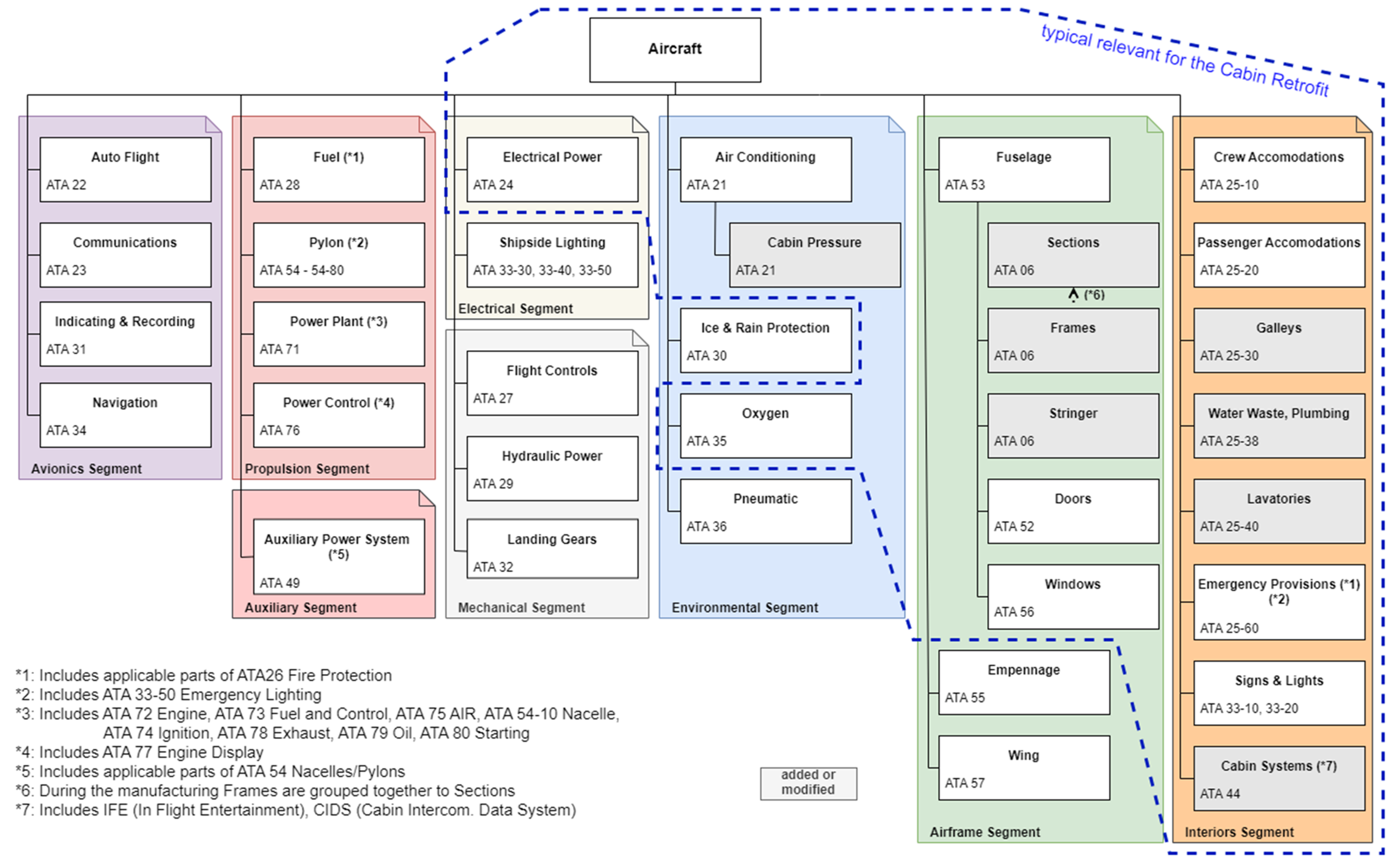
iSpec 2200, published by ATA in the year 2000, extends this system and updates it to better include current technology. In the industry, many documents or visualizations are labeled using ATA chapters to declare which element of an aircraft is referenced. Not uncommonly, ATA chapters are even used within file names or workgroup titles. As these chapters clearly define different systems and elements within an aircraft, they can also be used as a base for an aircraft system architecture. Referencing the ATA Spec 100, Jackson created a visualization of a typical aircraft system architecture and its ATA chapter correlation [
7]. Based on his work,
Figure 2 shows a typical aircraft system architecture, adapted to include more details about elements relevant to retrofit. The retrofit of commercial aircraft typically focuses on elements related to the cabin; thus, the most relevant elements of the system architecture are highlighted. Additionally, the aircraft system architecture was adapted to include elements of lower levels within the cabin, such as galleys and lavatories. Newer elements such as cabin systems (ATA 44), including the in-flight entertainment (IFE) or digital cabin intercommunication data system (CIDS), are added as well. Albeit targeting the documentation within aviation, the ATA chapters and the derived aircraft system architecture provide a good and structured base.
2.2. Current Data Handling Practices—PLM and Model Data Management
While PLM systems are used at times, they also face the challenges of system discontinuities and, thus, are mostly focused on the digitally available data of one single stakeholder. Additionally, they are currently mostly used from the perspective of a manufacturer or designer, managing the data of a product from its idea up to production, and not specifically considering every single created entity of the product after its production. From the view of the manufacturer, the bill of materials (BOM) is often the base for the physical item hierarchy, also defining the connections and interdependencies between single models and information. Within this context, Rios et al. state that “current PLM systems treat the product as a type of product and not as a unique digital instance that could have a one-to-one link with its corresponding physical one” [
8], as would be needed for the planning of the retrofit. Additionally, with the BOM-orientated structure, meta-information-like relations and interdependencies between data and separate documents are often not documented sufficiently. With all the presented factors of the process of retrofitting aircraft, the need for a thorough representation of individual specific airframes and also the challenge of creating and maintaining these representations become obvious. For simply storing CAD, PDF, and other files, there are already many implementations ranging from PLM systems to new approaches such as using multi-model databases (MMDs) [
9,
10]. Because of the given structures, the handling of data, especially the metadata such as relations, interconnections, and interdependencies between entities, becomes a key factor. Because solely BOM-oriented handling does not meet these requirements by itself, an additional layer focusing on the management of the occurring and needed metadata is required.
2.3. Current Data Handling Practices—The concept of Digital Twins
The very concept of handling up-to-date data of a physical asset in the form of a virtual representation can currently be found in the literature using the term digital twin. Hence, a review of the history of digital twins and the relevant literature was conducted to gain insights into the current state of research and implementation. The origin of the concept of (virtual) representations of physical assets can be traced back to NASA and the Apollo missions in the 1960s [
11]. Much later in 1997, it was broadly described in scientific research [
12] before a more detailed description of the concept was published by Grieves et al. in 2002 [
13], and finally, the term digital twin appeared in 2010 in NASA’s roadmap for 2020 [
14]. Nowadays the concept is applied to a range of applications in different domains, with manufacturing being one of the most frequently occurring ones. Focusing on that domain, Kritzinger et al. published a visualization differentiating between digital model, shadow, and twin [
15]. This visualization is often cited and can be seen as the basis for one of the current most common definitions of digital twins for applications related to manufacturing. In 2020, the German Scientific Society for Product Development (WiGEP) described digital twins from the viewpoint of product development and the data occurring there [
16]. To briefly sum up the performed literature review regarding digital twins [
17], it can be stated that within the previously mentioned domains, they are often described as approaches for specific applications and focus on sensorial or state-describing information, rather than geometric or product-descriptive information. Then again, the viewpoint of aviation and its retrofit as presented in this work has its very own circumstances that do not match with those described for manufacturing or product development [
17]. Some domains, such as manufacturing, have come a long way in implementing digital twins. Concurrently more refined definitions of digital twins have emerged focusing on different possible applications and sometimes contradicting each other. However, despite the different establishments in different domains, the concept of a virtual representation of a physical asset—nowadays simply called digital twin—can be seen as the common ground. Therefore, in the setting of this work and the presented scope, the digital twin is described more generally as a concept, which describes the linkage between (aspects of) a physical product or object and its virtual representation [
17].
No realization of such digital twins that can easily be adapted to the presented use case was identified in the literature. However, other fields such as the data sciences regularly face similar challenges regarding the handling of data. Thus, they are also reviewed and presented subsequently.
2.4. Current Data Handling Practices—Metadata Handling within MBSE
With the establishment of systems engineering (SE) in increasingly large projects, there was a need to support data handling within engineering and management processes. Model-based systems engineering (MBSE), or the “formalized application of modeling to support system requirements, design, analysis, verification, and validation activities beginning in the conceptual design phase and continuing throughout development and later life cycle phases” [
18], helps in that regard, by moving from a mainly document- or paper-based documentation to a model-based documentation. Within the then-called model-based systems engineering, information is handled using centralized system models, e.g., in the form of graphical SysML models [
19,
20] allowing for a digitized single source of truth. Within a system model, there can be multiple different views, considering different aspects of the system. Especially across different applications there can also be multiple system models, each focusing on different aspects [
21]. Complementary authoring tools such as NoMagic’s Cameo Systems Modeler (Cameo) support the engineers creating these models and also allow for performing analysis of the information and relations.
Delligatti describes the modeling aspects of MBSE by referring to the three pillars of “modeling language”, i.e., the already named SysML, “modeling tools” such as Cameo, and a “modeling method”, which is “a documented set of design tasks that a modeling team performs to create a system model”. With the document-based approach to systems engineering being “time-consuming and error-prone” and “inconsistency [being a] problem”, he postulates that “MBSE—when practiced correctly—is the solution” [
22].
In recent years, starting with the utilization in MBSE, the usage of SysML and the respective visual diagrams have come a long way. While information can be easily modeled in such system models using the respective authoring tools, accessing the information from external processes currently remains challenging. Currently, no independent file format has been established, and the authoring systems include only a few to no application programming interfaces (APIs). Nevertheless, today SysML is used and adapted to a range of applications. The technique of documenting information, especially meta-information, within system models is adapted to tasks and applications outside of the scope of systems engineering [
23]. Likewise, focusing on product architectures, Dambietz et al. showed that a model-based approach can be a feasible way to face the challenge of handling product metadata and results in an enhanced consistency and continuity of data while also enabling the digital processability of the information [
24].
Model-based documentation, inspired by the works within SE and MBSE, can help in other domains facing challenges regarding the handling of data and meta-information. However, it should always be clear that doing so does not imply that the solution is then to be categorized as MBSE, but just that tools and techniques originating from MBSE are used. With system models based on SysML, and MBSE in general, currently being implemented increasingly in the industry, the general availability of information in a model-based form is increasing. This will eventually lead to a generally improved exchange of this information in a formalized format. With the currently ongoing works on the renewed SysML V2 standard and its planned implementation into authoring systems, the lack of interfaces for the modeled information from external processes might be solved in the future [
25]. However, as of the end of 2022, there are only prototype implementations to be found, and the predominant authoring systems currently do not support the new standard.
2.5. Current Data Handling Practices—Approaches within the Data Sciences
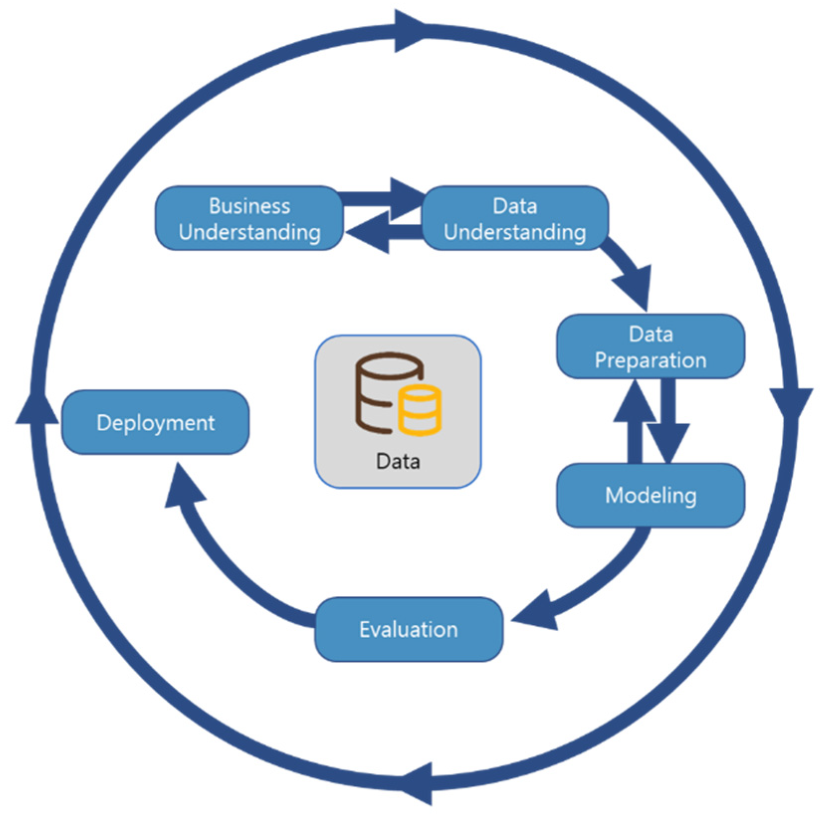
The very goal of gaining insights into and improving the usage of already existing data can also be found in the domain of data sciences. Despite a very different situation, as often the data is already digitally available in their databases, structuring it and identifying connections (implicit and explicit) are common tasks. As data is their everyday business, data scientists have developed classifications and methodologies. The
Cross-Industry Standard Process for Data Mining (CRISP-DM) is one of the most applied process models in data science. It divides the process of data mining into six phases: business understanding, data understanding, data preparation, modeling, evaluation, and deployment [
26]. The standard process of CRISP-DM and its six main phases are visualized in
Figure 3. Each of these phases consists of multiple steps, which are described on a general level and guide the operator through a path of aspects and tasks that need to be considered when planning and conducting a data-mining project. Because of this description on a general level, CRISP-DM can be and also needs to be tailored to the specific circumstances, and in general, extensions are easily possible. For this reason, CRISP-DM is broadly accepted in data science and can be found in various implementations [
27].
It is often adapted or extended to the specific application by adding relevant elements, aspects, or steps [
28]. In a previous work [
29], such an extension of CRISP-DM was briefly presented. This extension incorporates steps to define the needed information for a digital representation and later on identify missing data as well as provide strategies on how to acquire said information. However, it focuses mainly on the first tasks: identifying what data is needed and strategies for acquiring additional information. In the later phases of CRISP-DM, there are tasks regarding the modeling of data, which need to be further specified and tailored to the given scenario.
In the data sciences, information, especially about relations, is often stored in graph databases or models. Within graph databases, objects and their relations are modeled using the abstraction of nodes and edges, with the edges representing the relation between two objects. With this abstraction, graph databases are especially good at modeling entities and the connections or dependencies between them [
30]. As they originate from IT projects, graph databases such as Neo4j have good connectivity features and, thus, can be easily integrated into projects using APIs and programming libraries. Because these databases are a generic platform, there is no easy user interface for creating the models; instead, the user has to enter the data using a specific textual query [
31].
2.6. Conclusions on the Current Data Handling Practices
Our literature study regarding digital twins has highlighted the origin of the term and identified the common aspect among the different approaches: virtual representations of physical assets. While there are many different approaches to be found, most of them focus on product creation and especially development and manufacturing. There, progress has been made; however, the circumstances that the application to aviation retrofit brings along greatly differ. With model-based documentation originating from MBSE and data science’s CRISP-DM methodology, two approaches were identified, which can support the data handling regarding the retrofit in aviation. With the authoring tools and system models found in MBSE, creating and handling information in a model-based manner instead of purely document- and paper-based is introduced. As SE and MBSE are currently rising within the industry, an increasing amount of information will be stored in system models and, thus, in the future will be already available in that format. The authoring tools also allow the user to create models and store new information using a user interface. However, because the authoring tools are designed mainly with actual systems engineering tasks in mind, factors such as easy integration into completely different ecosystems and APIs are currently not primarily focused on. Then again, graph databases, such as those commonly found in data science projects, are exceptionally good and integrative because of standardized APIs. However, information can only be added and read via specialized queries, and not modeled visually like SysML system models. A combination of both, visually modeling the initial dataset, then transferring the information into a graph database for easy integration into processes and user interfaces, is a feasible solution. PDM and multi-model databases are established solutions for the storing of data. As the previously described system models and graph databases focus on the relations between information and metadata, these two approaches complement each other.
2.7. Research Scope
Regarding the presented scenario, the following research question stands to reason: How can available meta-information regarding aviation and its retrofit be digitally defined and documented so that its usage eases the access to required but fragmented information during the planning and execution of aviation retrofit?
Initial research as well as the state of the art of relevant topics, as has been presented in this section, lead to the hypothesis that a model-based approach documenting known relevant meta-information and relations in combination with techniques originating from the data sciences can provide a strategy to iteratively create virtual representations of aircraft aggregating the relevant information for the specific aircraft, and thus supporting the engineers planning and performing the cabin retrofit. An overarching procedure enabling the occurring (meta-) information within the depicted scenario iteratively supports the implementation of the presented concept.
3. Methodology
The current documentation in aviation retrofit is characterized by a variety of relations and interdependencies. The described challenge of handling the occurring meta-information can also be found in other fields of the broader context of product development. Based on the knowledge and experience of Dambietz et al. [
24], a similar model-based approach to support data handling in aviation retrofit is chosen. More precisely, a procedure based on CRISP-DM and targeting a model-based approach to digitally document implicit and specific known relations as an assistance to the data handling in aviation retrofit is developed. In this section, the key elements of the methodology are presented, including the overarching procedure as well as the base for system models.
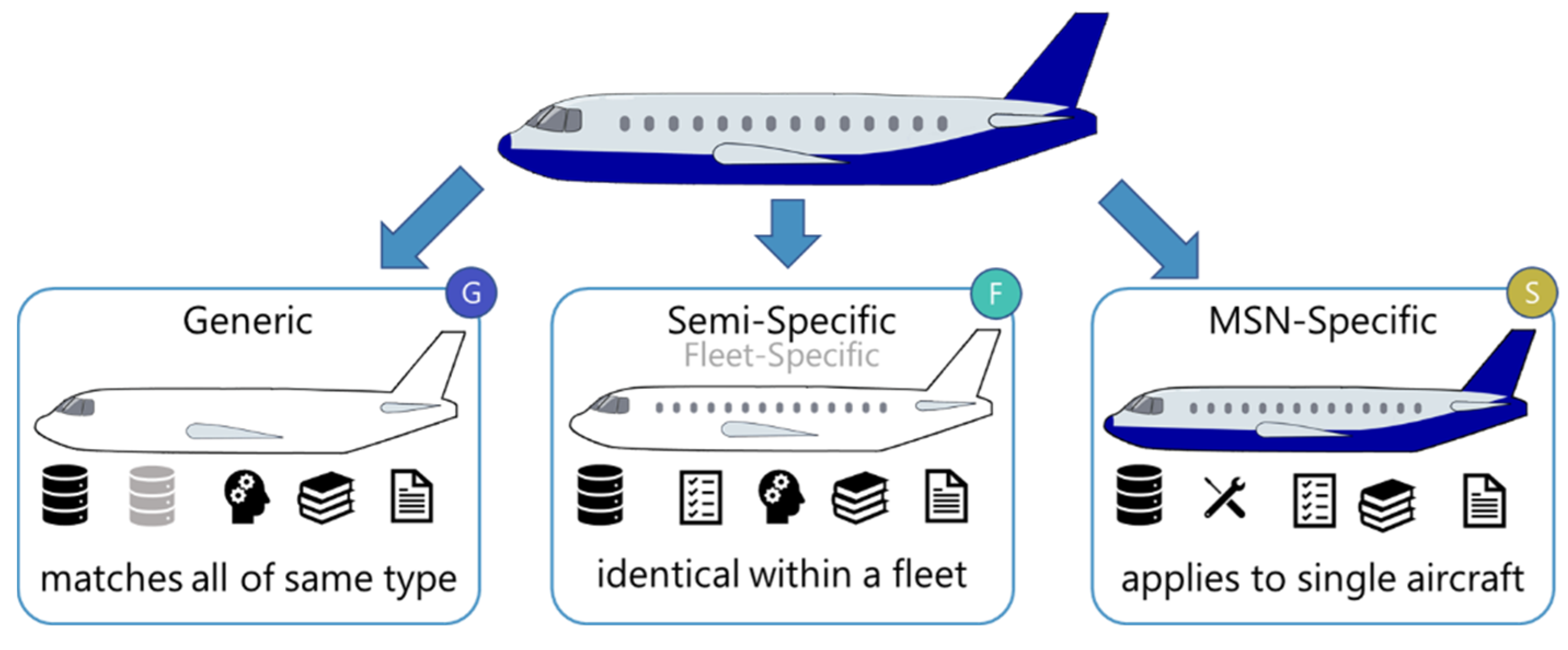
As the number of types of occurring aircraft is manageable but nevertheless all aircraft of the same type are not equal, the specificity of information becomes a key factor in handling the data: Some of the relevant information is airframe-specific, while other information is generic and can be applied to other aircraft as well. Generic information only needs to be modeled once and then can be applied to other specific models as well, while specific information is only relevant for a specific entity of aircraft. Each of those individual and unique aircraft is identifiable by its manufacturer serial number (MSN), allowing for a simple association of specific information. Additionally, with aircraft often being operated as part of an airline’s fleet targeting a specific route or range, the cabin itself as well as the operations and maintenance cycles are also comparable for a specific number of aircraft. Thus, when an aircraft is part of a fleet, information that is available from a previously handled sister aircraft can still be more accurate than the generic information of the aircraft type. In any case, it is better than having no information at all. Here, tracing the source and the reliability of information is essential. These three described basic levels of specificity—the state of being specific rather than general—are depicted in
Figure 4. With a more diverse structure within airlines and their fleets, a more granular distinction might be possible. However, this article focuses on these three intuitive levels to describe the general approach.
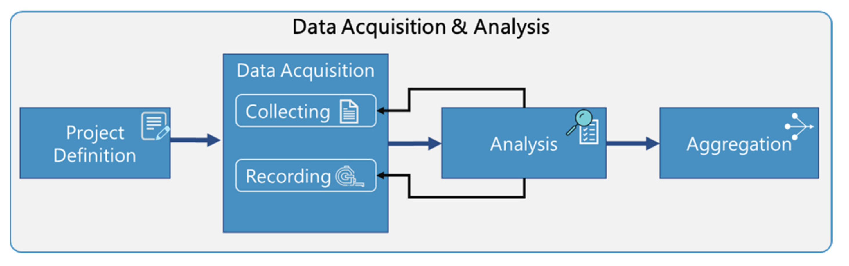
Generic information applies to all aircraft of the same type; for example, all (standard) A320 aircraft are 37.57 m long or have their front doors located between frames 16 and 20. Within the semi-specific set of an airline’s A320 fleet, all aircraft might have the same seat layout and installed cabin monuments (such as galleys and lavatories). On the most specific level, bound to a specific manufacturer serial number (MSN), there can be individual adaptations such as structural reinforcements placed during maintenance. If this specific aircraft was the first of the fleet to be equipped with new components, the respective information is also categorized on this level. Nevertheless, holistically gathering and structuring all possible information about a complete aircraft consisting of millions of parts is a vigorous task, especially for a third-party stakeholder such as a retrofit organization. Besides the general approach of data reusability through the levels of specificity, a methodical approach to focusing on the parts of the aircraft and the selection of information required for the respective application is needed. As not only the management of the available information is a necessity, but also the acquisition of new or additional information, the general methodology is based on CRISP-DM. It is adapted and extended to the specific needs of this application. With the identification and acquisition of additional information as well as a guide to support the implementation of the modeling itself, the approach is further complemented. Despite the focus on the later phase of modeling, a brief overview of the phase of acquisition and analysis is shown in
Figure 5 and described subsequently.
Some aspects of CRISP-DM’s first phase “business understanding” occur here before the acquisition and analysis of data during the “retrofit planning”. There, the overall scope of the cabin retrofit and respective points of interest within the airframe are defined. Relevant information might also originate from project management activities during that phase. The acquisition and analysis itself starts with the phase of the project definition during which the required information about the aircraft is defined based on the points of interest. In this procedure, the CRISP-DM phase of data understanding is split into two phases: data acquisition and analysis. The data acquisition focuses on the actual acquisition of the previously defined information either in the form of collecting already available information from different sources or by creating new (digital) information by accessing the actual airframe and, for example, performing measurements or visual inspections. During the analysis phase, the acquired information is further analyzed and inspected. This is not to be confused with data analytics and analysis found in the later phases of CRISP-DM. Instead, it is similar to the CRISP-DM phase of data understanding. While not part of such an overlying procedure, this work is currently also done manually and for each retrofit. With more and more information available in models and, thus, easily accessible forms, this task will eventually require less and less manual work. As part of this process, it will also be decided whether all required information is available with sufficient quality, specificity, and reliability or whether new information needs to be collected or recorded. Hence, iterative loops back to tasks of the phase of acquisition are possible. Additionally, at this step, the actually required information is filtered from all the acquired files and data. With all information available, the phase of data aggregation is started. During the aggregation, information from the different sources of the acquisition is aggregated into a dataset that can be handed to the modeling. Additionally, occurring references and dependencies as well as meta-information such as the sources, reliability, specificity, and also referable IDs are reviewed or added.
Once the acquired data has been analyzed and aggregated, it is modeled and stored to be digitally usable. While the documents and files themselves can be stored in file servers or PLM systems, the relations and meta-information are modeled using system models similar to the system modeling language SysML. While much of the information is often highly specific, more generic information such as the relations and dependencies between components of the aircraft cabin can provide a benefit when it is digitally accessible using models. Hence, the very base of the system models is a generic model of the aircraft, its cabin-relevant components and systems, and their relations. Additionally, available organizing structures such as the ATA chapters are implemented in the models. An overview of the modeling phase is shown in
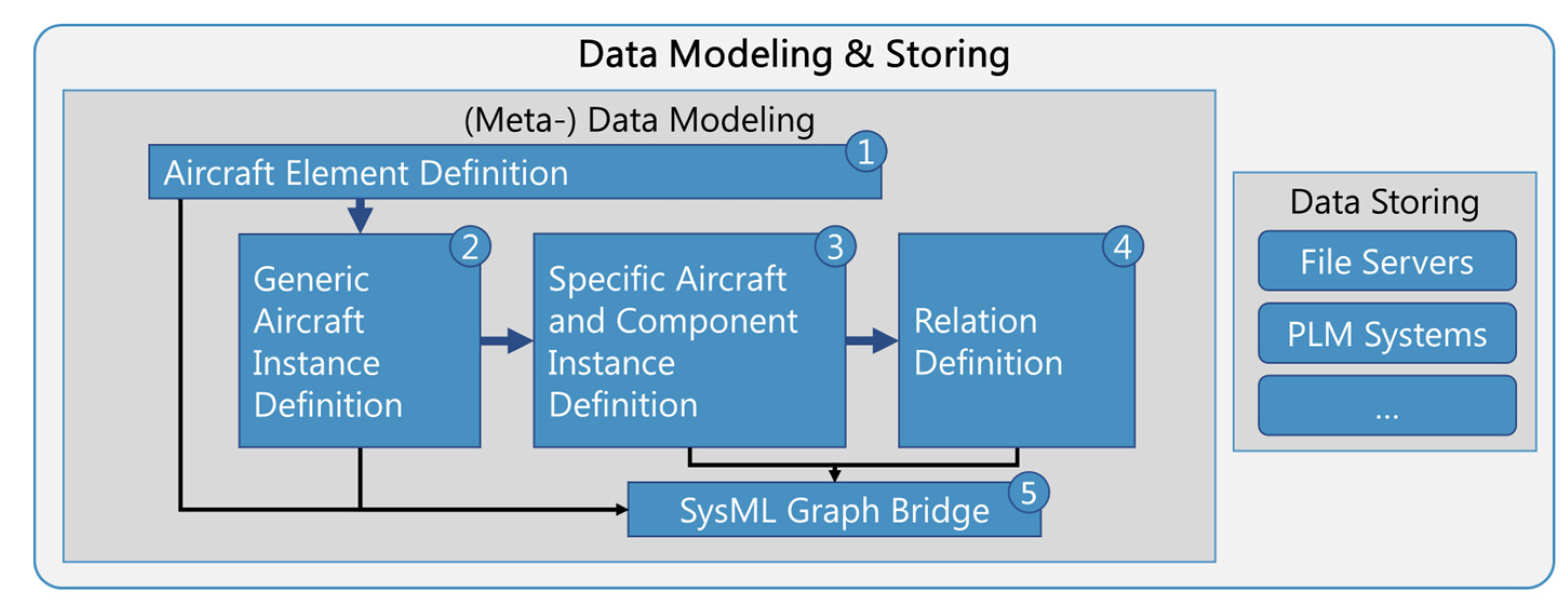
Figure 6 and described subsequently.
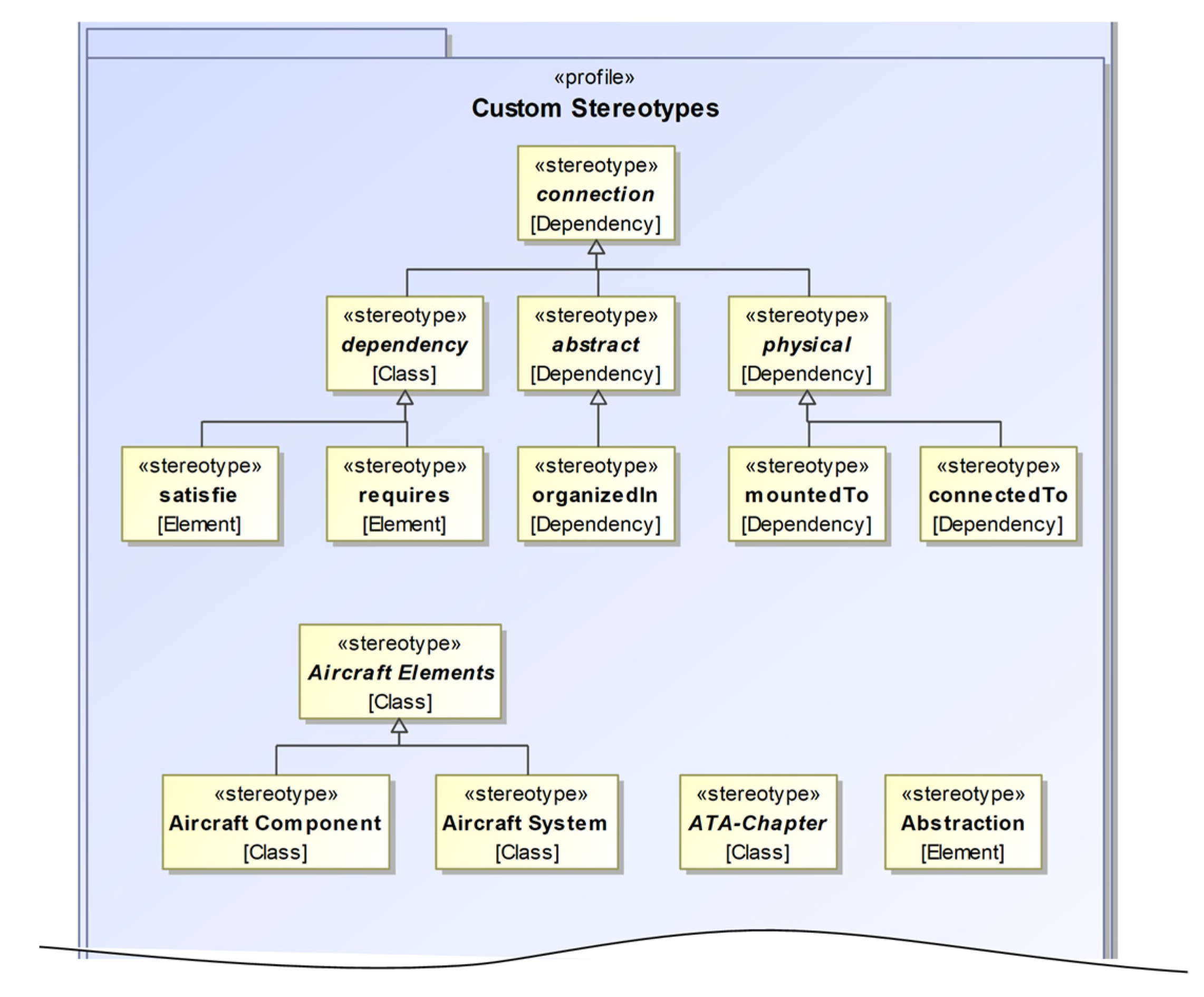
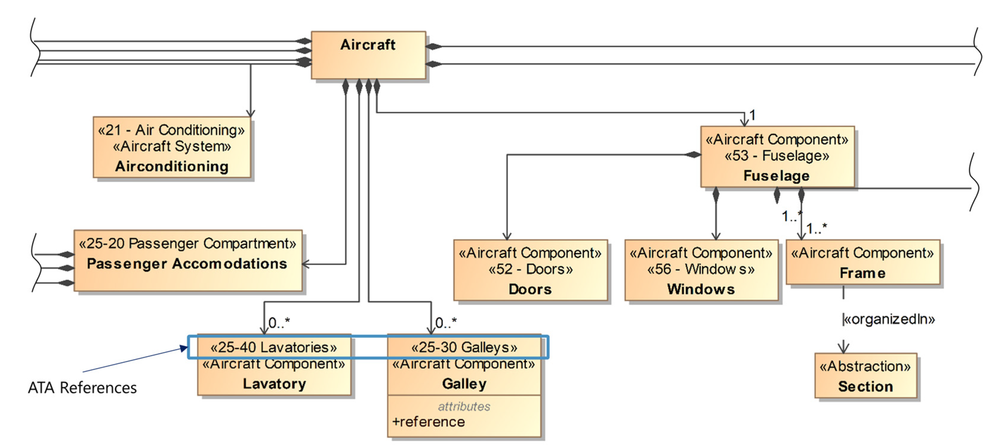
The first step in the modeling phase is the definition of the aircraft elements: the system and component structure of the relevant parts of the aircraft cabin. As most of the information modeled in this step is on the most generic level, the greater part of it only needs to be modeled once per type of aircraft and can be reused afterwards. In case new components need to be incorporated during the current project, they first have to be added at this level. The modeled information is comparable to that of a product structure of a product family, albeit incorporating more specialties of aviation. For example, the skeleton of the airframe of an aircraft consists of several frames onto which many of the other components will be mounted later on. References to ATA chapters can already be implemented at this point.
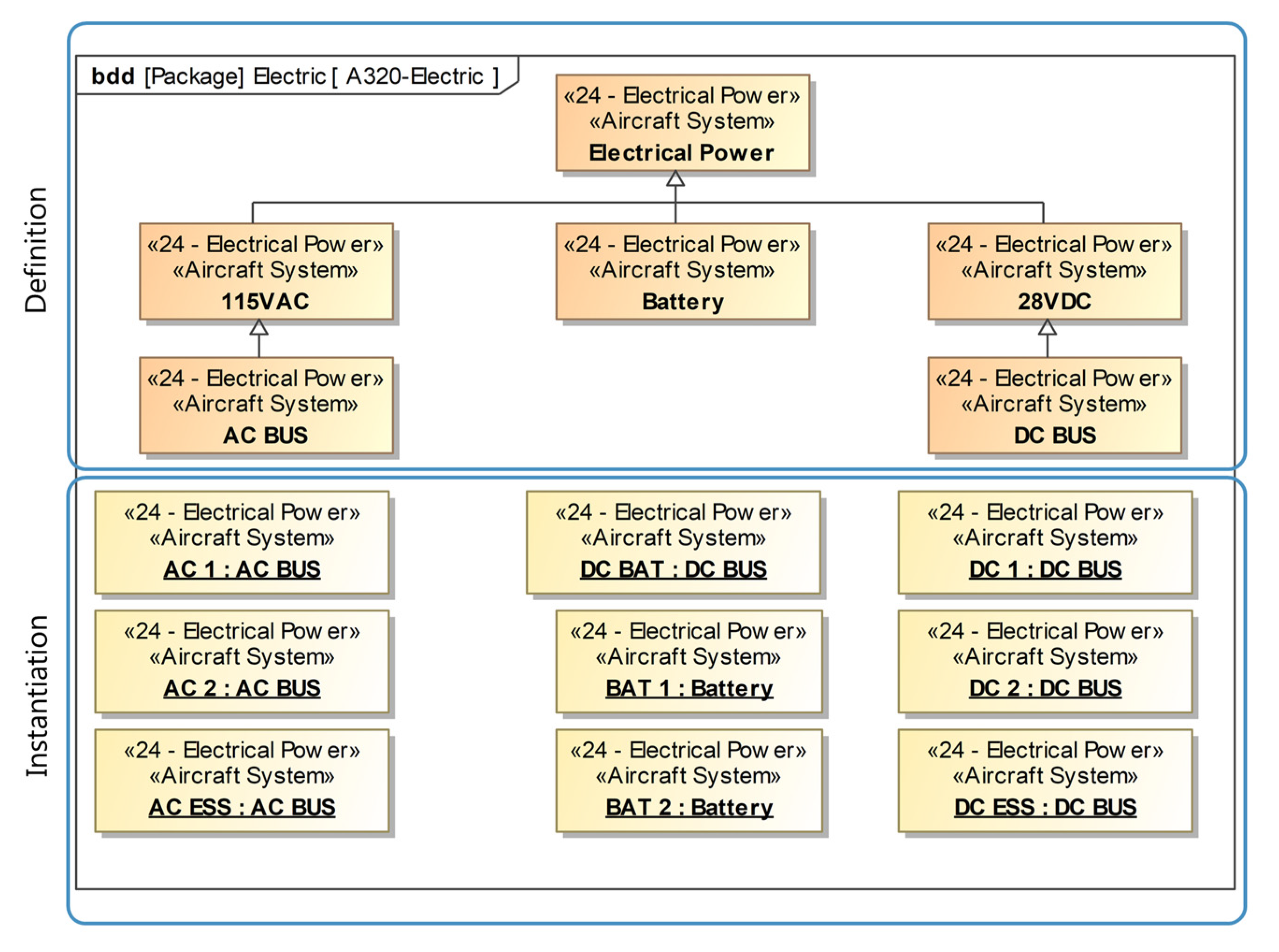
With the generic cabin structure and, thus, the available systems and components defined, the next step is the definition of the generic aircraft itself by instantiating the respective components. Components or structures occurring multiple times are instantiated accordingly and given unique referable IDs. For example, an A320′s airframe consists of 87 individual frames; hence, there are 87 instances of the structural component frame. As this information again is highly generic, it only needs to be modeled once and then can be reused for every other A320.
In step 3, more specific levels of information are modeled, according to the levels of specificity. With different views, more and more information about the aircraft and its cabin is added by adding the respective numbers of instances of the respective structures and components.
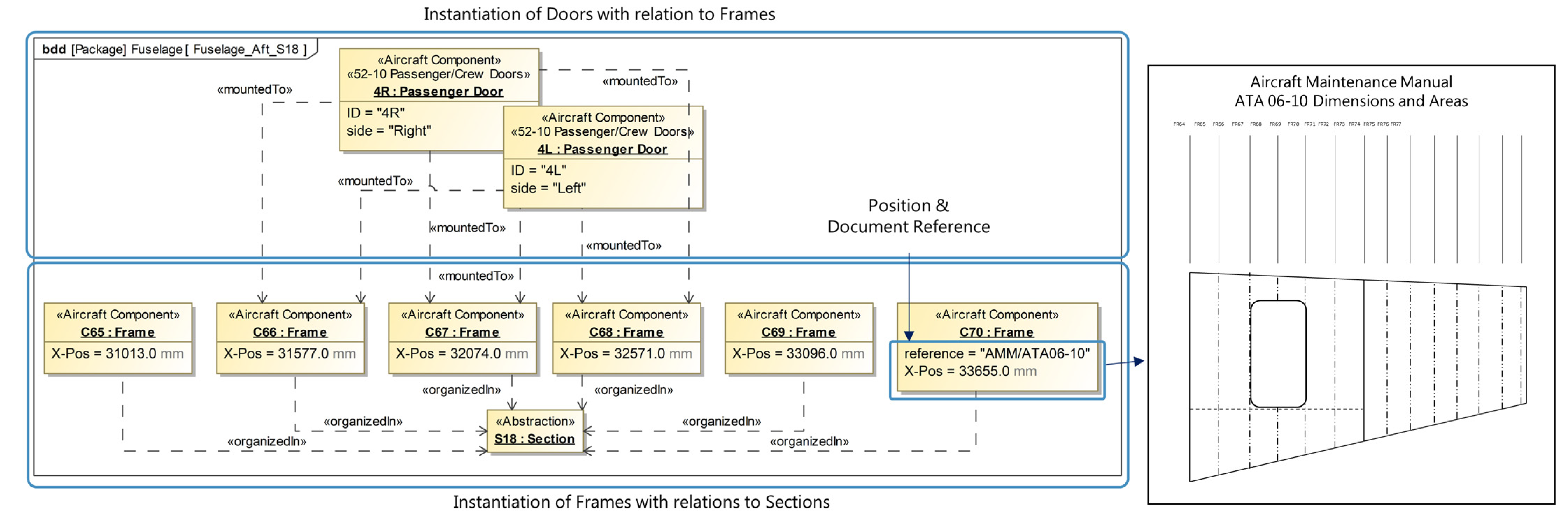
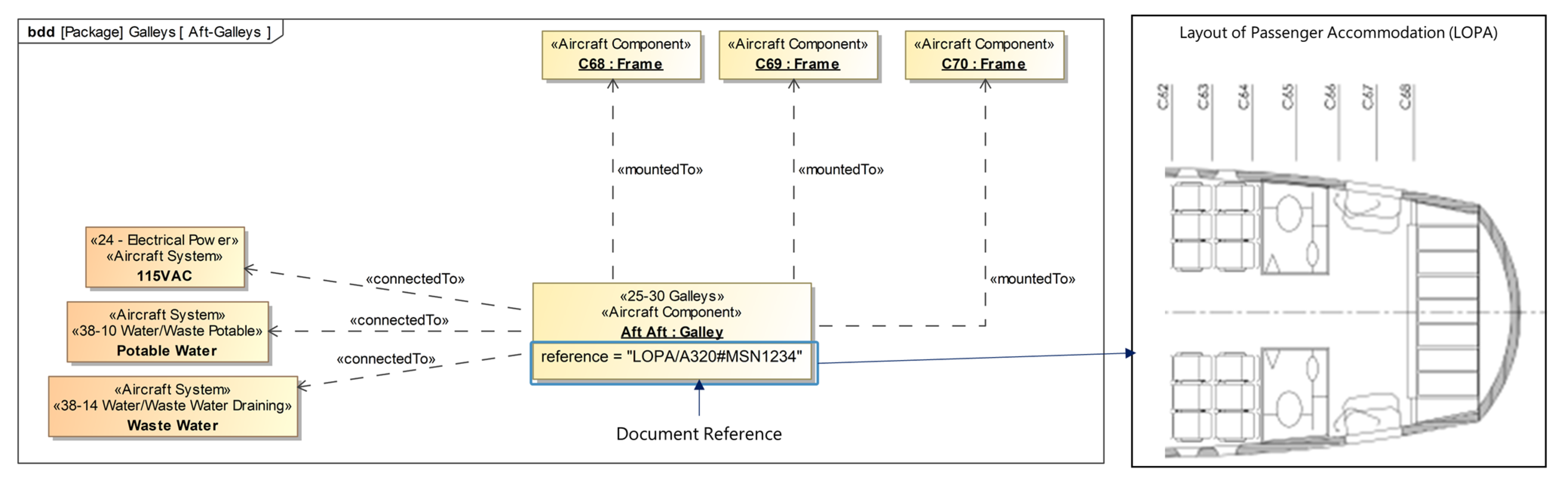
Henceforth and especially in step 4, the single-source-of-truth aspect of system models and the used authoring tools become beneficial as during this step the relations between the previously added instances are defined. Because each instance is clearly defined once within the model but can be used multiple times within different model views, a structured approach to the definition of these relations is possible. This is considering the clarity of the model and also the different occurring domains. For instance, the position of a lavatory can be defined relative to a specific frame within one view, while in another view the installed air conditioning relates to the same frame. These references can nowadays also often be found within the existing PDF documents, but they are not digitally usable. Within the model, these relations can be further defined by type (e.g., mounted to) and also references to the documents the information is derived from and other meta-information such as date and source of data acquisition.
These four modeling steps result in a system model of the aircraft cabin including references to ATA chapters, and also to external files. Documents on stored servers or within PLM systems can be either referenced directly via hyperlinks or using unique document IDs. These external references allow for a simple link from the presented data handling to state-of-the-art data storage solutions. Hence, the storage and access management of the data can be realized using existing IT infrastructures. Because of the comforts of the authoring tools, for example, Cameo, including user interfaces and single-source-of-truth management, the creation of these models can be performed by engineers with no expertise in programming. Additionally, the creation of system models and the usage of these tools are part of the rising trend in the industry towards the usage of systems engineering and model-based systems engineering with similar approaches. While this assistance during the creation is beneficial, the lack of good interfaces for the modeled information (see
Section 2.4) is challenging. On the other hand, graph databases are not only visually comparable to the created system models but can also include the same information needed for this application. Because of their good application programming interfaces, they can easily be used for accessing the stored information; however, the initial creation of the information requires either programming knowledge or a custom-built user interface.
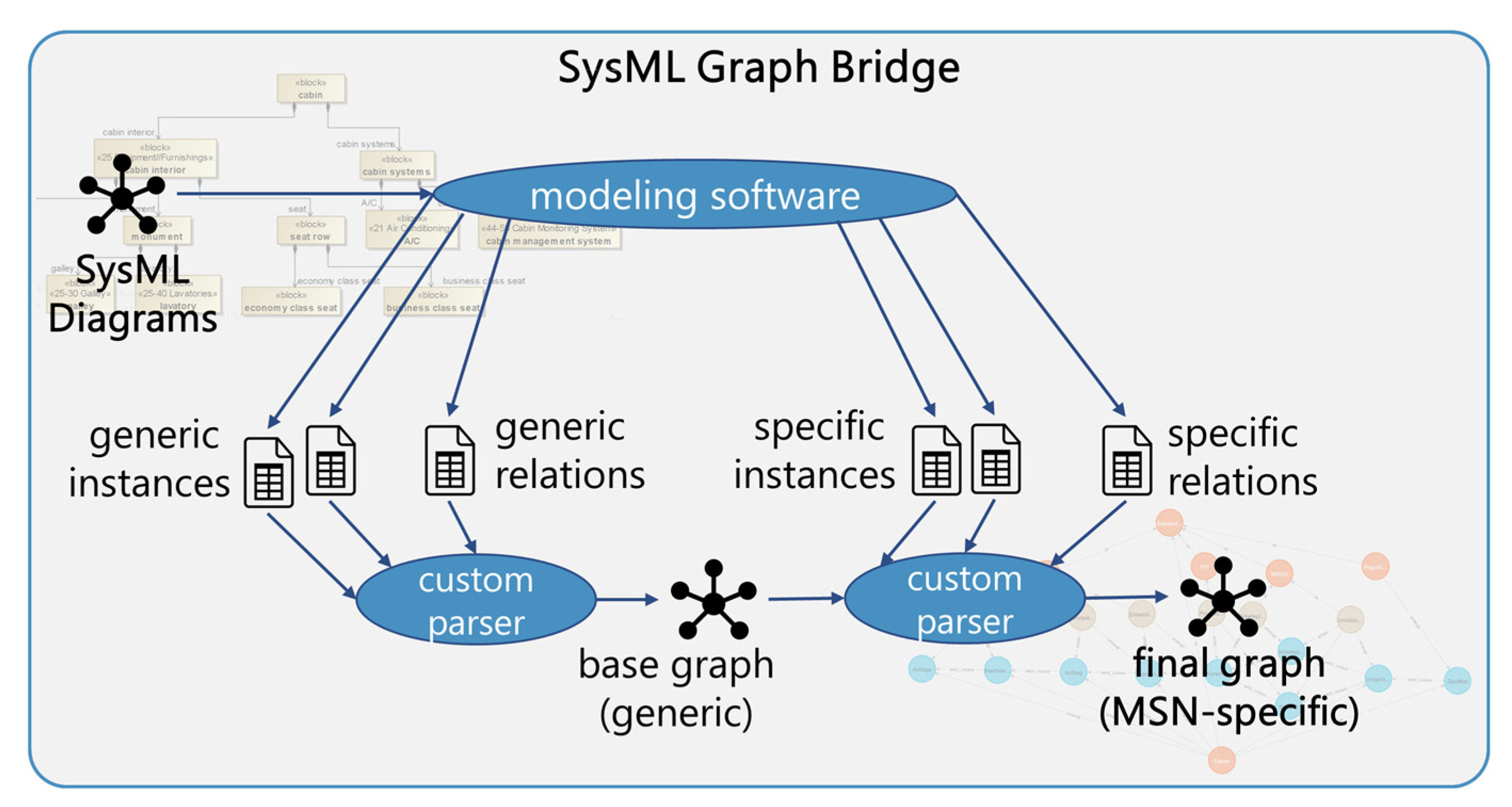
To combine the benefits of these two domains, the fifth step is the usage of a custom-built SysML graph bridge, which uses exported data from the system models to create a graph database including all previously modeled information. Based on the modeled information, tables of instances can be automatically created within the authoring tool. Not only instances of elements but also all instances of relations can be captured that way. These instance tables include all modeled information from all selected views in a structured way and, thus, can be easily parsed after being exported to CSV files. The custom-built SysML graph bridge then parses these sets of CSV files and injects the information into the graph database while automatically identifying the unique element instances and creating the relations according to the relation instances (cf.
Figure 7). Once the information is then stored in a graph database, it can easily be accessed using a standardized API and, thus, from nearly every other process or program with the possibility to implement custom API calls. Graph databases, which are regularly used for data analytics within the data sciences, also allow for a more extensive analysis of the modeled information. This, however, is part of future work.
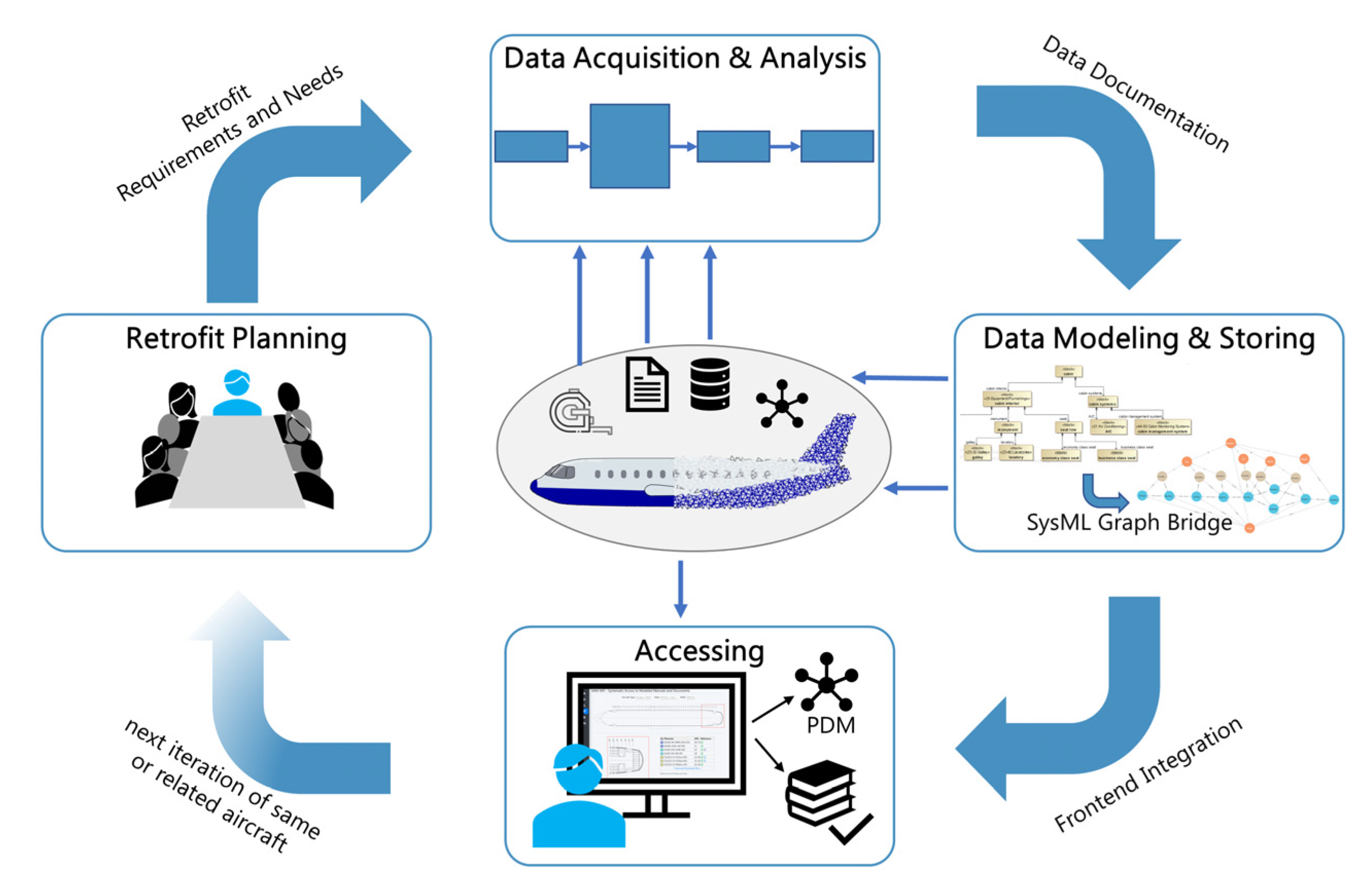
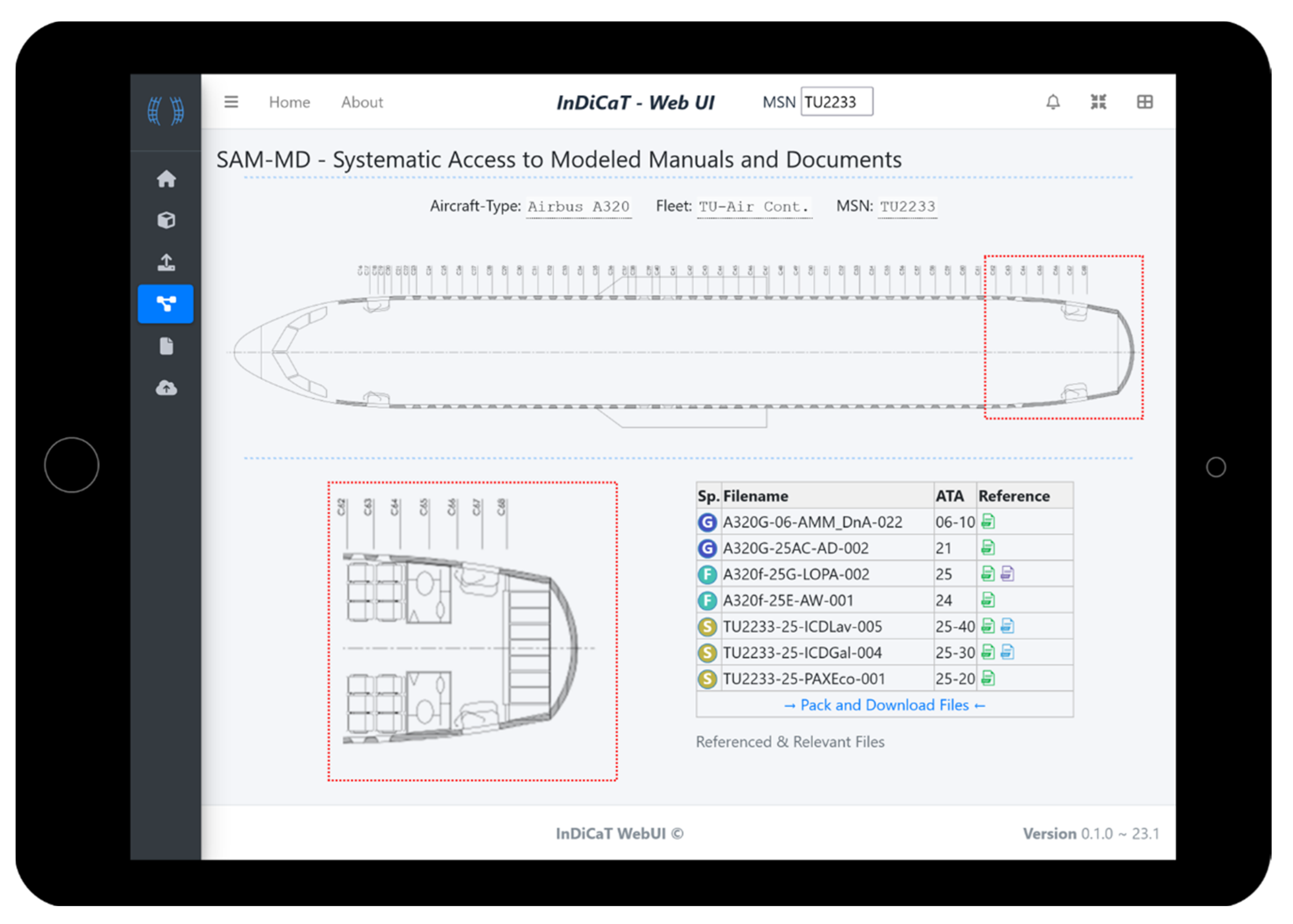
Within the presented procedure, this transfer to a graph database primarily enables the modeled information to be used by a range of different applications. In combination with the references to actual CAD or PDF files emerges a virtual representation of the specific aircraft. Such an application is part of the frontend integration during the last phase of the procedure. An example application is an integration into a user interface that assists the engineering during the design of the new cabin. This makes the previously mostly analog information digitally available during the retrofit. Because the relations and dependencies are now digitally parsable, different queries are possible. When needing information regarding a point of interest within the cabin of a specific aircraft, the selection of a frame can automatically result in a list of all components referring to that frame including the respective documents or files. An installation of a new component can be planned by identifying possible mounting positions based on information on what systems are required and where these are currently available in the airframe. With each aircraft being processed and modeled, the dataset is accumulating and increasingly more information will be available during the next iteration and thenceforth. Thus, the phases iteratively use and reuse the central database. The general approach presented in this section is visualized in
Figure 8.
5. Discussion and Conclusions
Aviation is characterized by a unique combination of circumstances: Complex products with long lifespans encounter many stakeholders. High safety standards and maintenance procedures require thorough record keeping and also result in a vast number of documents. Whenever an aircraft is retrofitted with a new cabin—approximately every 5 to 7 years—the organization planning and executing this retrofit is faced with the challenge of designing a cabin that perfectly fits into the unique airframe without having a simple-to-use representation of the specific asset. Because at the time of planning, the aircraft is still in operation and flying around the world, a simple acquisition of the current state is often not feasible. Instead, the engineers plod through the pile of documents, often only knowing where to look next based on experience. While aviation standards such as the ATA chapters help by providing a common referencing standard, many dependencies between documents, which originate from the conjunction of different domains and elements within an aircraft cabin, are still hard to manage manually. After presenting the state of the art in aviation documentation and approaches regarding the handling of data occurring in other domains, this article has presented a model-based approach to assist in the handling of the documentation needed for the retrofit in aviation. Structured digitalized documentation is created by first defining generic information about aviation and aircraft, thus providing a basis for specific implementations while also improving the reusability of information. Subsequently, information specific to a single aircraft is added to the system model. The modeling is extended by a bridge from the created system models to a graph database. This allows for easy integration into user interfaces and furthermore enables usage of data science algorithms later on. The modeling approach is embedded into an overarching procedure, based on CRISP-DM, which also includes the definition of the retrofit as well as the phase of data acquisition.
Combined with classical data storage solutions such as PLM systems or file servers, the approach enables the implementation of digital twins of specific aircraft focusing on the information needed for the retrofit. Because of the iterative approach and improved reusability of generic information, this now becomes possible even for third-party stakeholders as retrofit companies usually are. Previously, the concept of digital twins was mainly possible to implement for the product creator or manufacturer. The retrofit engineer would have had to go through many files manually, searching for relevant sections. Now, using the presented approach and user interface, a brief overview of relevant documents is given, and if linked, direct access to related files is provided from within the web application. Digital twins of aircraft, consisting of thousands of parts, are hard to implement, especially for a third party. This challenge remains even with the presented approach. However, the retrofit often does focus on a specific area of interest, and the similarity between aircraft allows for the reuse of information if done carefully and strategically. Thus, the goal is not to have a holistic twin of each aircraft all at once, but to organize the information used in each retrofit in such a way that over time the work becomes increasingly less difficult. While the use of system models is rising in the industry and a growing number of engineers are familiar with their creation, the access to the modeled information from external programs is intricate. The presented approach solves that issue by transferring the modeled information into a graph database. With the new standard SysML V2 on the horizon, this issue might be solved in the future. However, the general approach is unaffected by that, as the focus is on the system models, and once a direct interaction with them is possible, the user interface could be tweaked to directly access them instead of the graph database.
Referring to the research question presented in
Section 2.7, this work has presented a model-driven approach to support data handling in aviation. The modeling of available meta-information and implicit data allows for digital assistance that helps to compile the fragmented information required to perform the planning and execution of aircraft cabin retrofit. While this by itself does not create digital twins of aircraft, the combination of generic and specific information allows for easier handling of the individual information of specific aircraft while also improving the overall data reusability. By combining this with state-of-the-art data storage systems, the possible implementation of digital twins of specific aircraft is supported. Hence, the presented work can be seen as a precursor and enabler for implementing digital twins of aircraft within the depicted scenario of aviation’s cabin retrofit.


