Article

Modeling and Analysis of Unmanned Aerial Vehicle System Leveraging Systems Modeling Language (SysML)

1
Engineering Management Department, College of Engineering and Computer Science, Arkansas State University, Jonesboro, AR 72401, USA
2
Systems and Industrial Engineering Department, The University of Arizona, Tucson, AZ 85721, USA
3
Department of Industrial Engineering and Management, Khulna University & Engineering Technology, Khulna 9203, Bangladesh
4
Complex Engineering Systems Laboratory, Department of Informatics and Engineering Systems, The University of Texas Rio Grande Valley, Edinburg, TX 78539, USA
5
Department of Systems Engineering, Colorado State University, Fort Collins, CO 80523, USA
*
Author to whom correspondence should be addressed.
Systems 2022, 10(6), 264; https://doi.org/10.3390/systems10060264
Submission received: 16 October 2022 / Revised: 2 December 2022 / Accepted: 16 December 2022 / Published: 19 December 2022

Abstract

:
The use of unmanned aerial vehicles (UAVs) has seen a significant increase over time in several industries such as defense, healthcare, and agriculture to name a few. Their affordability has made it possible for industries to venture and invest in UAVs for both research and commercial purposes. In spite of their recent popularity; there remain a number of difficulties in the design representation of UAVs, including low image analysis, high cost, and time consumption. In addition, it is challenging to represent systems of systems that require multiple UAVs to work in cooperation, sharing resources, and complementing other assets on the ground or in the air. As a means of compensating for these difficulties; in this study; we use a model-based systems engineering (MBSE) approach, in which standardized diagrams are used to model and design different systems and subsystems of UAVs. SysML is widely used to support the design and analysis of many different kinds of systems and ensures consistency between the design of the system and its documentation through the use of an object-oriented model. In addition, SysML supports the modeling of both hardware and software, which will ease the representation of both the system’s architecture and flow of information. The following paper will follow the Magic Grid methodology to model a UAV system across the SysML four pillars and integration of SysML model with external script-based simulation tools, namely, MATLAB and OpenMDAO. These pillars are expressed within standard diagram views to describe the structural, behavior, requirements, and parametric aspect of the UAV. Finally, the paper will demonstrate how to utilize the simulation capability of the SysML model to verify a functional requirement.

1. Introduction

A UAV system generally consists of the air vehicle, ground control system (GCS), mission planning and control stations (MPCS), payload and communications links, navigation system, and the launch, recovery, and transportation systems. The air vehicle consists of subsystems such as the airframe, engine, data connection, stabilizing devices, and flight command, as well as fuel, electrical energy supply, and fundamental construction. The payload consists of various sensors and equipment, such as color cameras, radar, etc. Information is collected by sensors for processing and utilized by drones. The information is transmitted to the central operation center and also saved in the drone for easy retrieval. The navigation system helps the UAV to identify its location because it is necessary for autonomous flying. The launch and recovery system assists the UAV during autonomous takeoff. The primary function of the communication system is to facilitate interconnects between the control station and the air vehicle [1]. GCS or MPCS is the UAV system’s operational control center and makes it possible to create a task and track a UAV flight [2].
There is some limitation to UAVs, for instance, the risk of cybersecurity breaches in UAV systems, The data transmission channel’s flaws, the power supply limits of UAVs, limited flight time, and untrustworthy communication models [3]. To overcome this problem, we need to establish a well-defined model of UAVs systems. Presently different illogical diagrams are used to represent UAVs systems that are not consistent nor comprehensive [4]. To fill this void, this study suggests utilizing model-based systems engineering (MBSE) to represent the UAV system model. MBSE brings the discipline of systems engineering into a modeling paradigm, while the SysML language adds rigor and definition to the ways a system model can be represented [5]. To apply the MBSE approach this study applies the OMG standard modeling language called the system modeling language (SysML). SysML is a multipurpose graphical language that allows users to see many aspects of a system’s architecture. SysML provides a set of syntax and semantics for system definition that can also be represented in a series of standardized diagrams that depicts the many elements that the systems engineering field requires [6]. The objectives of the study are summarized as follows:
  • To apply the MBSE approach to provide a standardized model of the design of UAV systems to improve safety, protection, and reduce human error;
  • To illustrate the use of the SysML diagram to increase transparency, traceability, and easy understanding of the interaction of elements of UAVs system and subsystems;
  • To demonstrate the interoperability of COTS simulation software and the SysML model to verify functional requirements;
  • To contribute to the literature on the application of MBSE in UAVs.
The remainder of the paper is organized in the following manner: Section 2 represents the literature on the use of SysML on UAV systems. Section 3 outlines the modeling procedure of the UAVs system with the help of SysML. Section 4 presents the SysML simulation. Section 5 provides a discussion of this study. Finally, the paper ends with the conclusion and the scope for future avenues.

2. Related Work

The application of SysML in UAVs has increased in recent years. For instance, Dzielski and Blackburn [7] presented a decision framework, as well as its implementation in SysML, which is demonstrated by the design of a hypothetical surveillance drone. In this study, an analytical approach based on SysML was used in conjunction with a multi-dimensional design and optimization tool (MDAO) in order to address a hypothetical surveillance drone problem. As a result of this study, it was concluded that in SysML, it was possible to specify a decision framework that could be implemented with an underlying framework for cross-domain analysis. A recent study by Apvrille, Sannes [8] demonstrated the advantages of using an MBSE approach in the design of UAVs using SysML. Also, structural, behavioral, and requirement characteristics were considered when designing the architecture of UAVs. In Steurer, Morozov [9] study, they analyzed the UAV dependability profile using SysML. Dual-graph error propagation model (DEPM) was part of their methodology, while a method for converting SysML models to DEPM was developed. Xing-hua and Yun-feng [10] used a SysML-compliant tool called Rhapsody and Simulink to design UAV flight control systems. They created the virtual prototype of the Predator UAV to evaluate and confirm the system’s expected capabilities and behaviors. Queiroz and Braga [11] described a method for developing unmanned aerial vehicle (UAV) families that combines product line engineering (PLE) and model-driven engineering (MDE). The team recommended using SysML and the MARTE UML profile in order to assist with requirement specification, design, validation, simulation, and final code generation. They also suggested the use of the common variability language (CVL). The present study provides a method for developing family models of UAVs. Hernandez [12] developed an unmanned aerial systems (UAS) model using SysML and the No Magic tool Cameo Systems Modeler to monitor the information flow required for the operator situational awareness (SA). The results of the study showed that it is feasible to measure the elements of information acquired from the environment and transmitted to the operator via the UAS. Aljehani, Inoue [13] suggested a multi-UAV assessment with varied airframes. This study depicted a particle swarm optimization (PSO) method using a SysML activity diagram and deploying it to a multi-UAV with chosen airframes. The study’s findings revealed varied fitness values and the optimal site for various UAV airframes. MacCarthy [14] created the architecture of drone systems used for surveillance and delivery services by using SysML. They used structural and behavior models to represent the different architectural aspects of drones. They provided a reference design of the drone system and identified the type of analyses needed for designing a system. De Saqui-Sannes [15] presented a trade-off analysis in an MBSE approach that links SysML with “decision points” and this approach was examined using a model of multi-core UAVs and verified using a plug-in that they created using Papyrus and Eclipse. The algorithm in the study converts the expanded SysML model into a CSP optimization problem (CSMOP), which involves decision variables, limitations, and objective functions. This study showed that it is feasible to create the problem description file using a SysML extension and its plug-in rather than manually linking the SysML model with an optimization solution. Specking, Parnell [16] laid the groundwork for implementing the set-based design (SBD) with MBSE and an integrated framework for trade space exploration (TSE), demonstrating the methodology using an unmanned aerial vehicle (UAV) case study. This study demonstrated how the proposed approach could be utilized to (1) guide the formulation of system design requirements, (2) make a comparison of a greater number of design options, (3) upgrade the framework in real-time, and (4) offer additional data to assist decision-makers in selecting better performing designs at a reasonable cost. Aïello, Kandel [17] addressed a case study of MBSE and multidisciplinary design analysis and optimization (MDAO), with a drone as the case study and an emphasis on battery usage. In this study, a timed automata model of the battery was introduced to a SysML model of the drone, and results from the MDAO analysis were loaded into the battery’s SysML model. This study provided a way to increase self-confidence in some model values, increase self-confidence in the accomplishment of requirements, and refine some requirements values more precisely. Srivastava [18] used model-based systems engineering techniques to develop the theoretical design of unmanned aerial vehicles. The study’s approach was performed by assessing aircraft performance models, obtaining parameters of input and output from the models, generating model chains, and executing the models in the MATLAB programming language. The findings of this study offered a foundation for formalizing models typically used in conceptual airplanes, resulting in a more structured framework for the models to be implemented and reducing discrepancy and inaccuracies. Aloui, Hammadi [19] presented an MBSE method-based continuous methodology to design an efficient swarm of UAVs, and their approach was divided into the following three stages of the work: swarm modeling, swarm simulations, and swarm deployment. They used domain-specific language (DSL) to construct a new SysML model to represent the swarm mission, UAV swarm hardware requirements, and application platform of the swarm system. Wang, Sun [20] presented a technique for tracing modeling of command system-of-systems requirements based on SysML to address the issue of requirements tracing for adaptation strategies under the features of huge requirements, complicated relationships, and quick changes in the UAV command structure. In the technique, a multi-layer entire network built on SysML is employed to create a tracing model of the command system-of-systems needs through the top-down approach of assessing system-of-system needs. The outlined technique for creating a requirement tracing model made it easier to quickly develop a model of the command system-of-systems capacity needs and capture the top-down route that these requirements take.
Table 1 below represents the current theme of the application of SysML in UAVs.
In this literature review, not all the features of the SysML language have been discussed as being relevant to UAVs. A variety of structural, behavioral, and requirement features of UAV systems have been discussed in the literature, but very little information has been found on the SysML simulation of behavior diagrams to evaluate UAV functional parameters against requirements for UAV systems. This study pursues the following research questions:
  • How can the four pillars of the magic grid approach be applied to unmanned aerial vehicles domain?How to integrate external tool (such as MATLAB and MDAO) with SysML to simulate and optimize any potential parameters of unmanned aerial vehicle?
Within this study, we fill the void where behavioral, requirement, parametric, and structural aspects of the UAV have been modeled, including behavior modeling and simulation (through activity and parametric diagram) to cover different systems engineering design aspects for UAV. In addition, example basic calculations of UAV design and analysis were performed in external simulation tools, including MATLAB and OpenMDAO, and the results were integrated back into the SysML model that enables requirements verification and design decisions to be made within the SysML model. In addition to that, the paper demonstrated the integration of multiple tools with multiple SysML diagrams, which enables the potential users to determine which approach is easier for their particular modeling requirements. For example, the integration of external tools with a parametric diagram will be more efficient to enable complex calculations of the system than the activity diagram. On the other hand, an activity diagram enables the user to understand the flow and mechanics of the simulation/calculation being carried out by the external tool.

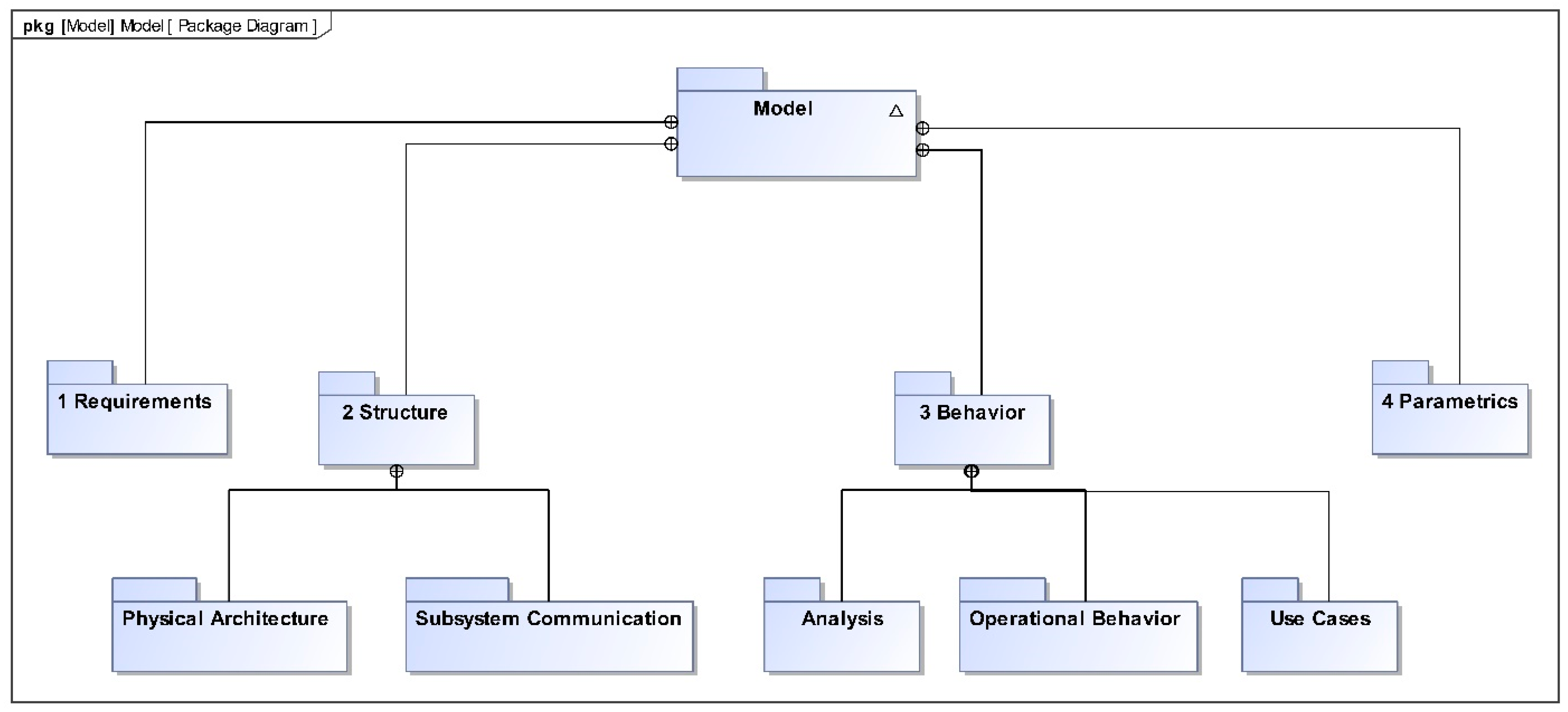
3. MBSE-Based Modeling Approach

Due to their efficiency and effectiveness in the delivery of food, medicine, and postal orders, drones have become increasingly popular in the logistics sector [21]. UAVs are also used in several countries for the purposes of security and criminal investigation [22]. As a method of border control and law enforcement, UAVs are heavily utilized in military operations as well [23]. To represent the UAV system, different types of diagrams of SysML are utilized, which describe the requirements, structure, and behavioral aspects of the UAV system. A requirement diagram is used to describe the requirements of the UAV system. A requirement diagram is a useful tool for practitioners to represent needs and track them across many components of the UAV system [24]. A block definition diagram (BDD) is developed using different components and linkages, such as blocks, composition, and association, to represent the hierarchy, ownership, and interfaces of a standard UAV system [25]. Another type of SysML diagram is the internal block diagram (IBD), which serves as a supplement to the BDD by enabling users to understand the relationships among certain blocks and the information flow between them [5].
The behavioral aspect of the UAV system is described by using a use case diagram and activity diagram. In the use case diagram, possible interactions between users and stakeholders with a UAV system are illustrated graphically [26]. An activity diagram is a type of behavioral diagram that shows the flow of functionality as “actions” and can have logic gates to represent multiple potential pathways of behavior. This type of diagram can be used to communicate information to various stakeholders [27].

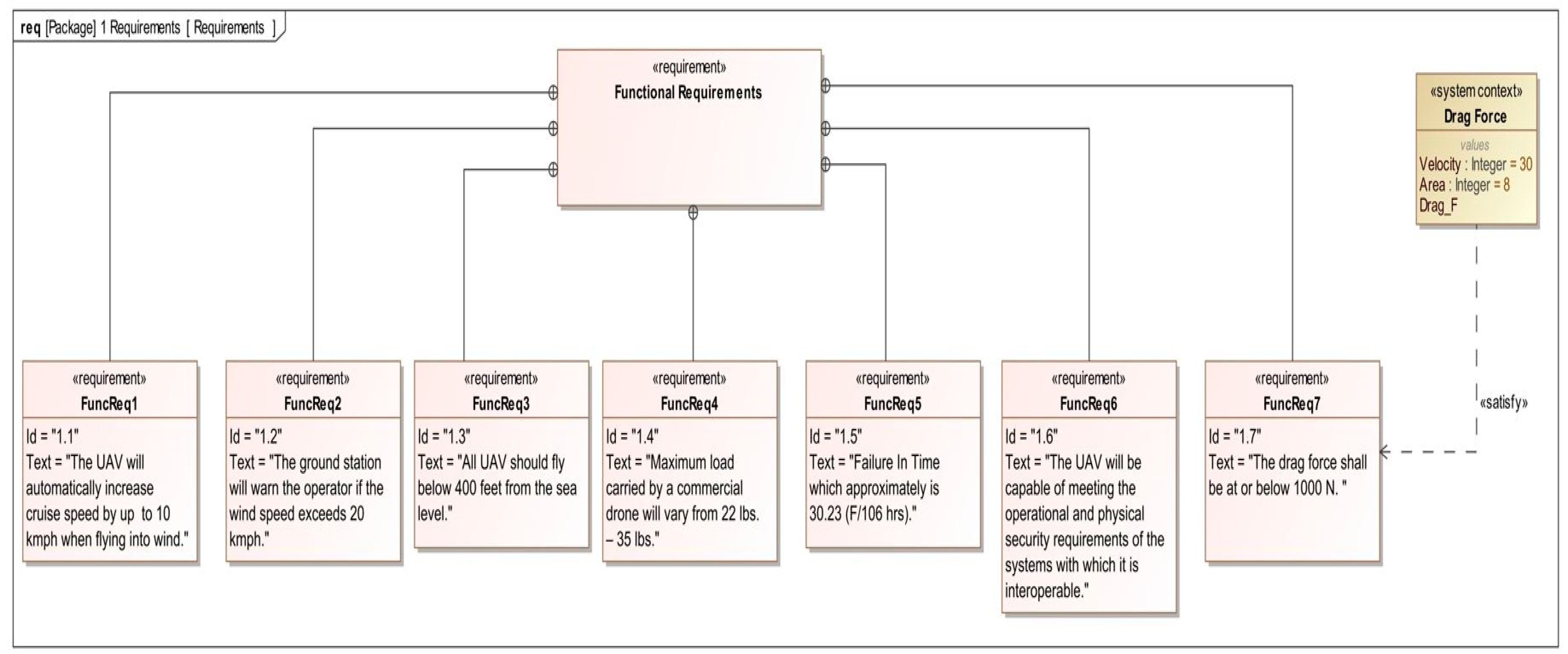
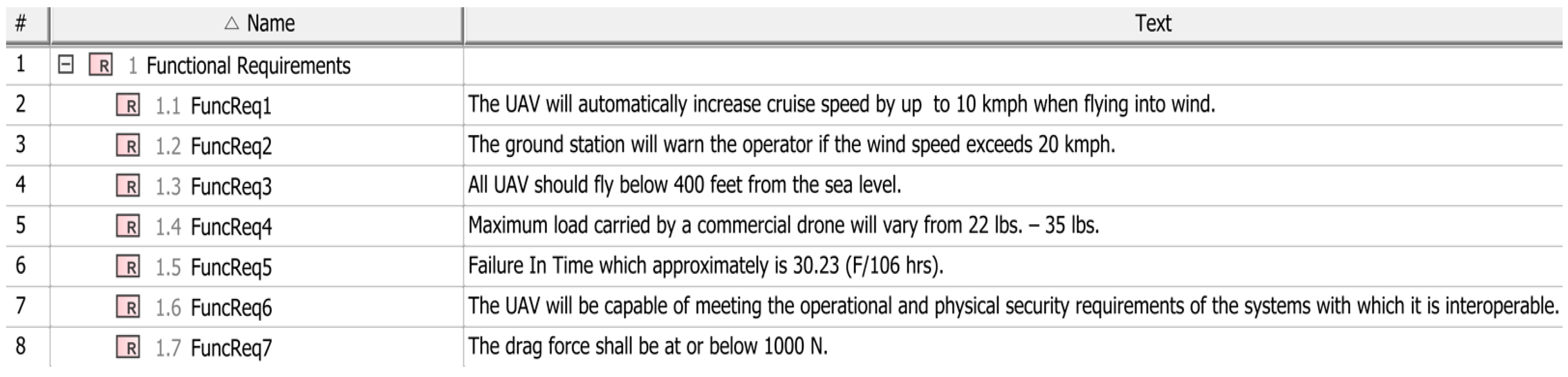
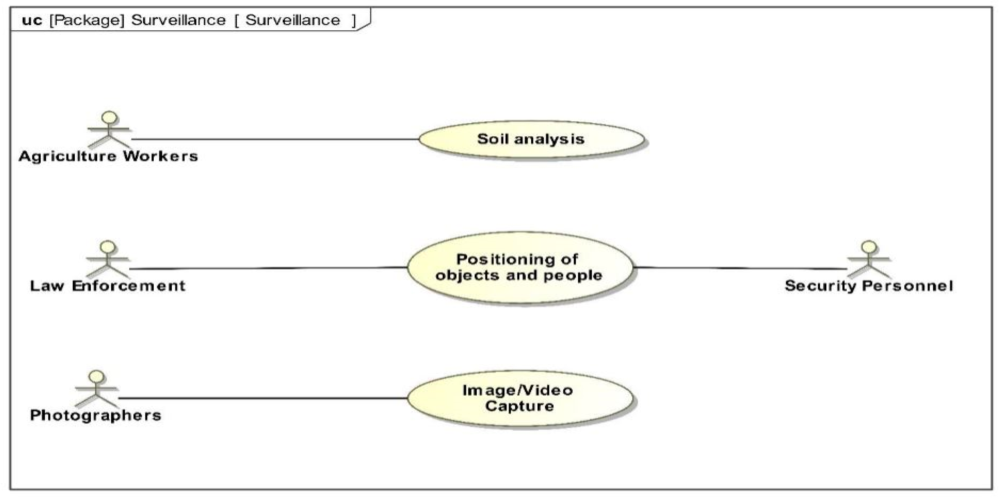
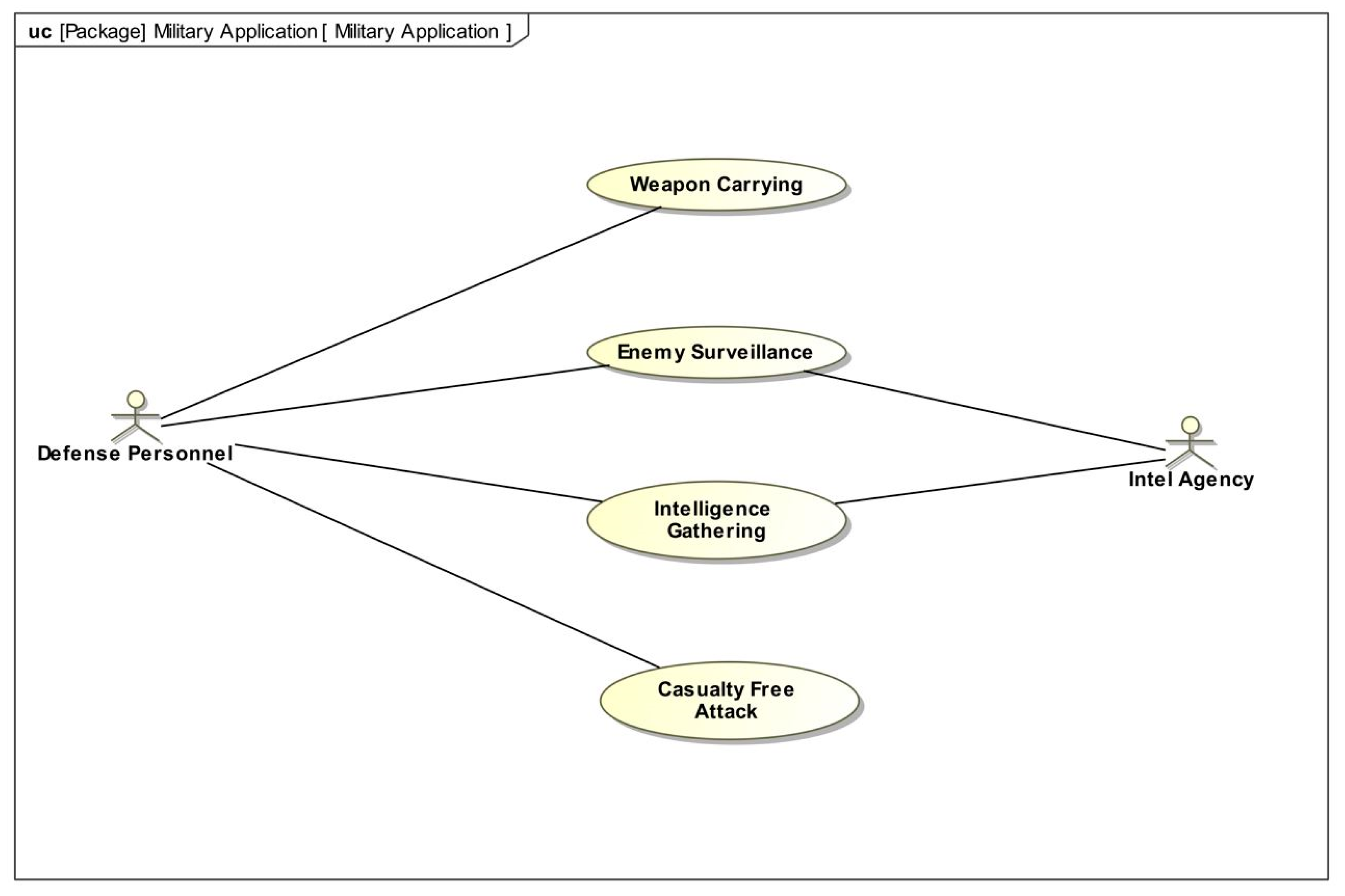
3.1. Development of Requirement Model

In this study requirement diagram is used to represent the requirements with text specifications. A requirement diagram represents text-based requirements and their relationships with other requirements and/or model elements and test cases to support requirements traceability [28]. Relationship types between requirements and requirements or other elements are containment, derive, refine, satisfy, verify, and trace.
In Figure 1, Functional Requirement-7 is satisfied by the “Drag Force” system context block. By having this relationship, the requirement can be verified using the simulation capability within the SysML tool. A requirements table is another form of requirement diagram, which can import or export the requirements to and from an excel sheet [28]. In Figure 2, the above functional requirements are shown in an easy-to-read “Requirements Table Diagram”.

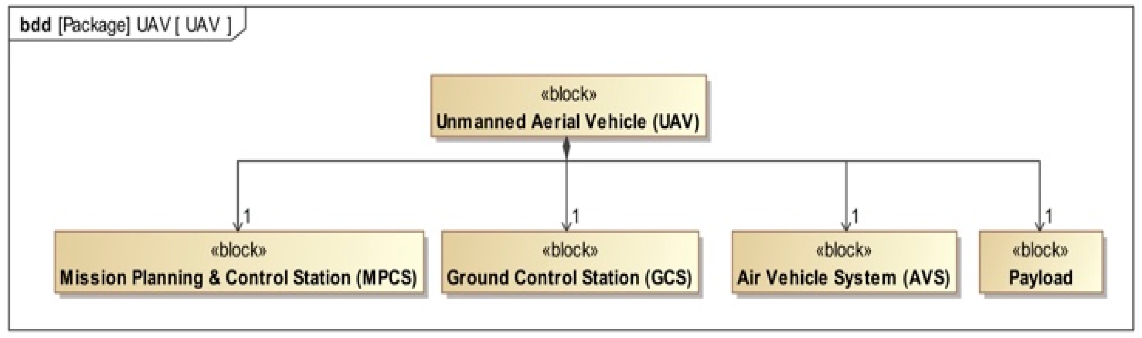
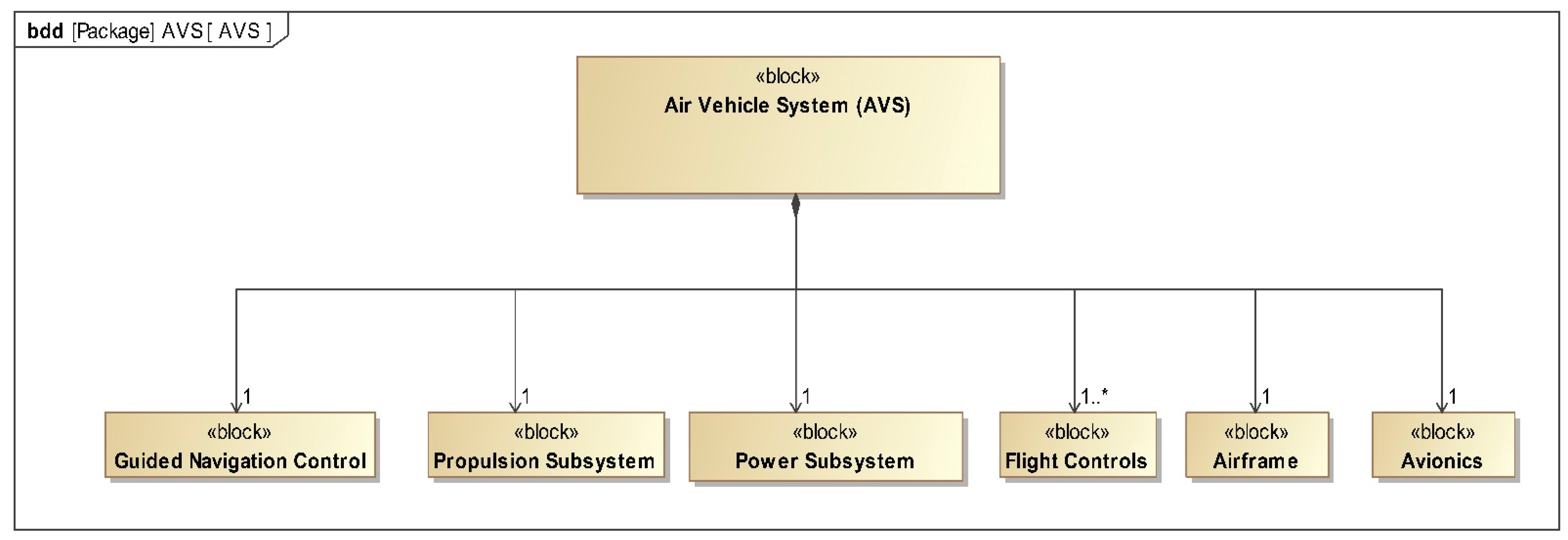
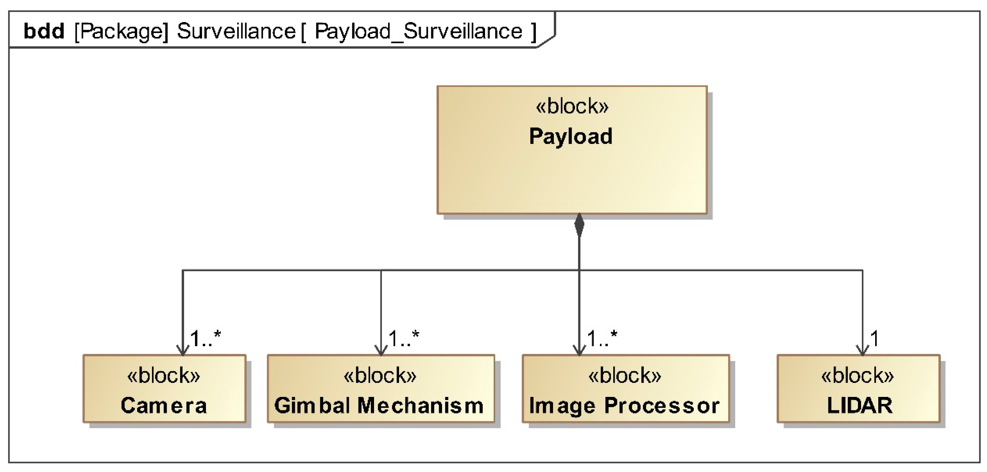
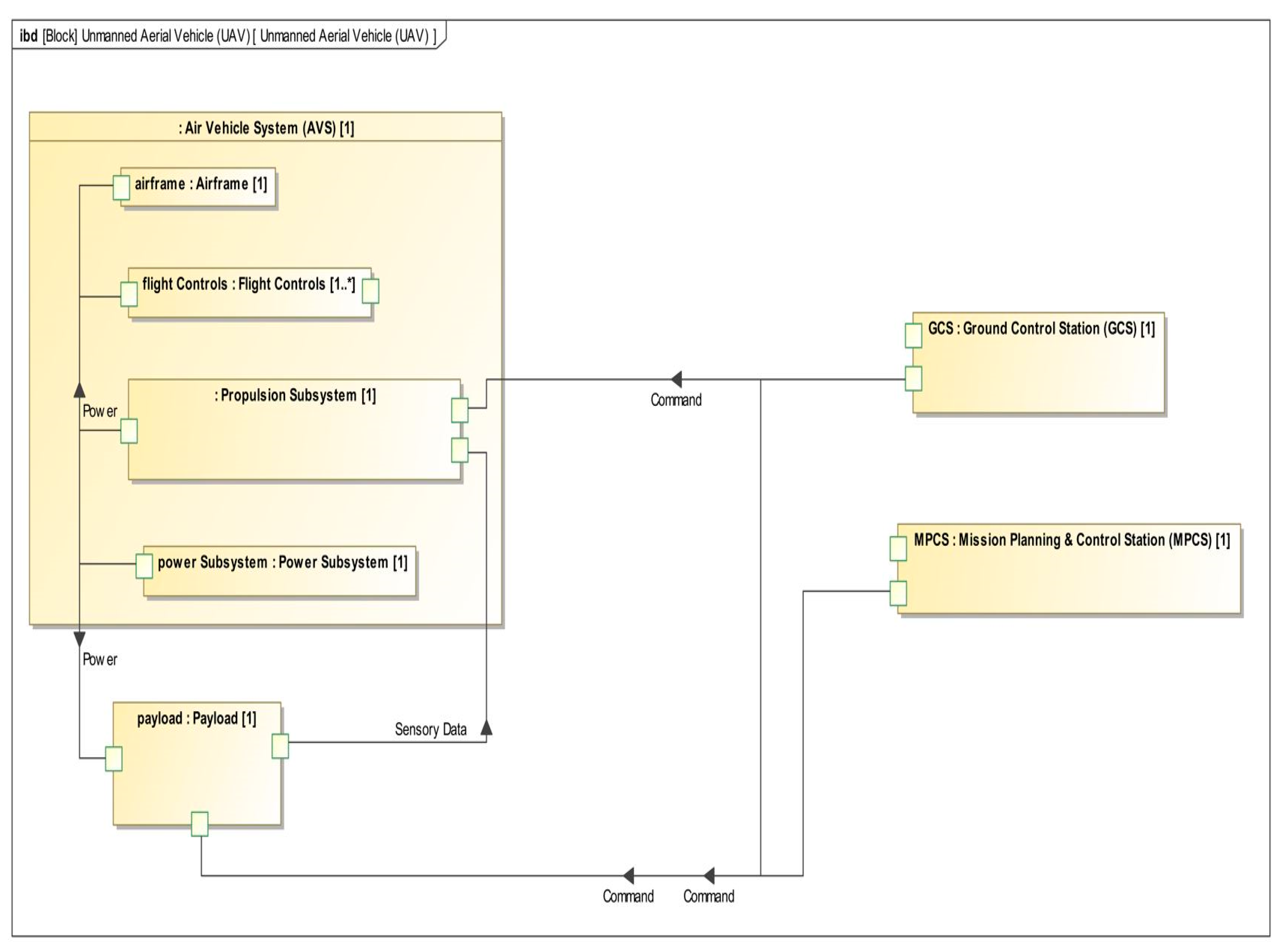
3.2. Construction of Structural Model

To visualize the overall organization of the model, a package diagram was initially created. The package diagram is simplified, lightweight, easy to implement, and recognized as module interconnection language. The package diagram converts the system into the module, which executes features of the product line for the control system version [29]. The package diagram also defines the dependencies and interconnections among other packages. Membership notations are also used in the package diagram to represent different membership [30].
In Figure 3, a package diagram is shown, representing the overall structure of the system model. A general package called “Model” is created to standardize the system. The general package is divided into the following three main packages: requirement, structural, and behavioral, as seen in Figure 3. The structural package contains the following two types of structural diagrams: block definition diagrams (BDD) and internal block diagrams (IBD). The package named Behavior contains use case diagrams, which represent the interaction of various actors with the systems, and activity diagram, which represent the different sequential activity of the system, and contain state machine diagram, which represents the concept of operations (ConOps) and different states of a system. The package called Requirements contains a requirement diagram of the system.
BDD visualizes the structure of the system [31]. A block can have different stereotypes depending on its usage [32]. For example, the system context stereotype is frequently used for defining the context of a simulation to be executed.
Figure 4 illustrates the different subsystems of unmanned aerial vehicles using a block definition diagram (BDD). The diagram shows the different elements of UAV, which are the air vehicle system (AVS), a ground control station (GCS), mission planning & control station (MPC), and payload.
Figure 5 represents the whole air vehicle system’s hierarchical breakdown. The diagram shows different subsystems of AVS, which are GNC, propulsion subsystem, power subsystem, flight controls, and airframe.
Figure 6 represents the payload components for the surveillance use case, which consists of camera, gimbal mechanism, image processor, and LIDAR. Payload can be reconfigured based on the application domain. In this Figure, asterisk sign (*) refers multiplicity.
An internal block definition diagram (IBD) is used to depict the relationships between the various subsystems of unmanned aerial vehicles. An internal block diagram (IBD) defines the system’s inherent architecture as well as the linkages between its components. Standard and flow ports represent the interfaces via which the components communicate, and interactions are expressed by pathways between the appropriate ports termed “connectors”. If a component fails, the failure will be propagated across the system through these channels [33]. More precisely, an internal block diagram (IBD) represents interconnection, interfaces, and ports between the parts of a block [25]. Signals can be sent from one port to another port through connectors to depict the transfer of data between the parts.
Figure 7 represents the internal block definition diagram of unmanned aerial vehicles. The diagram shows the signals and information flow among the subsystems of the UAV system. The asterisk sign (*) in this Figure refers multiplicity.

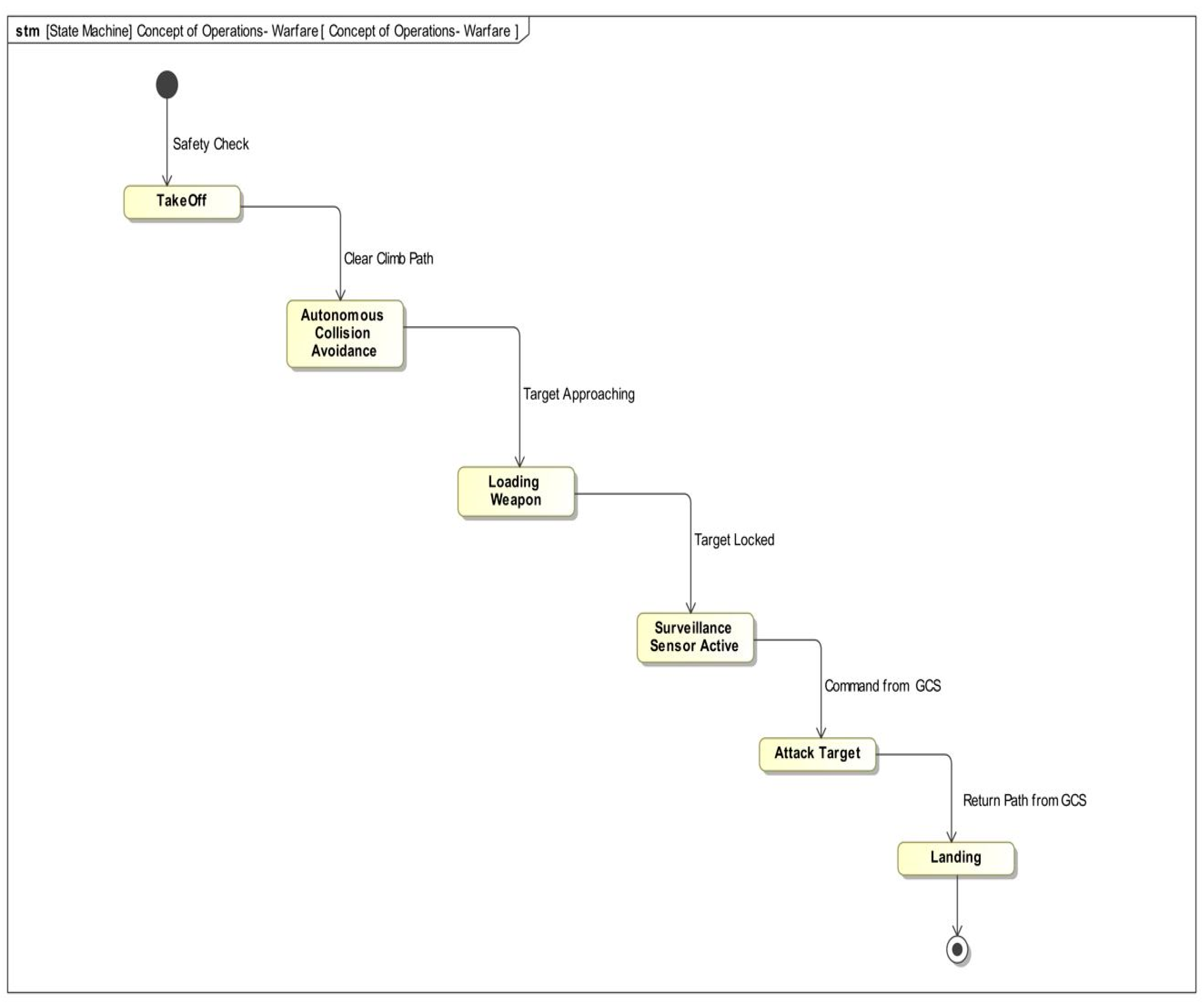
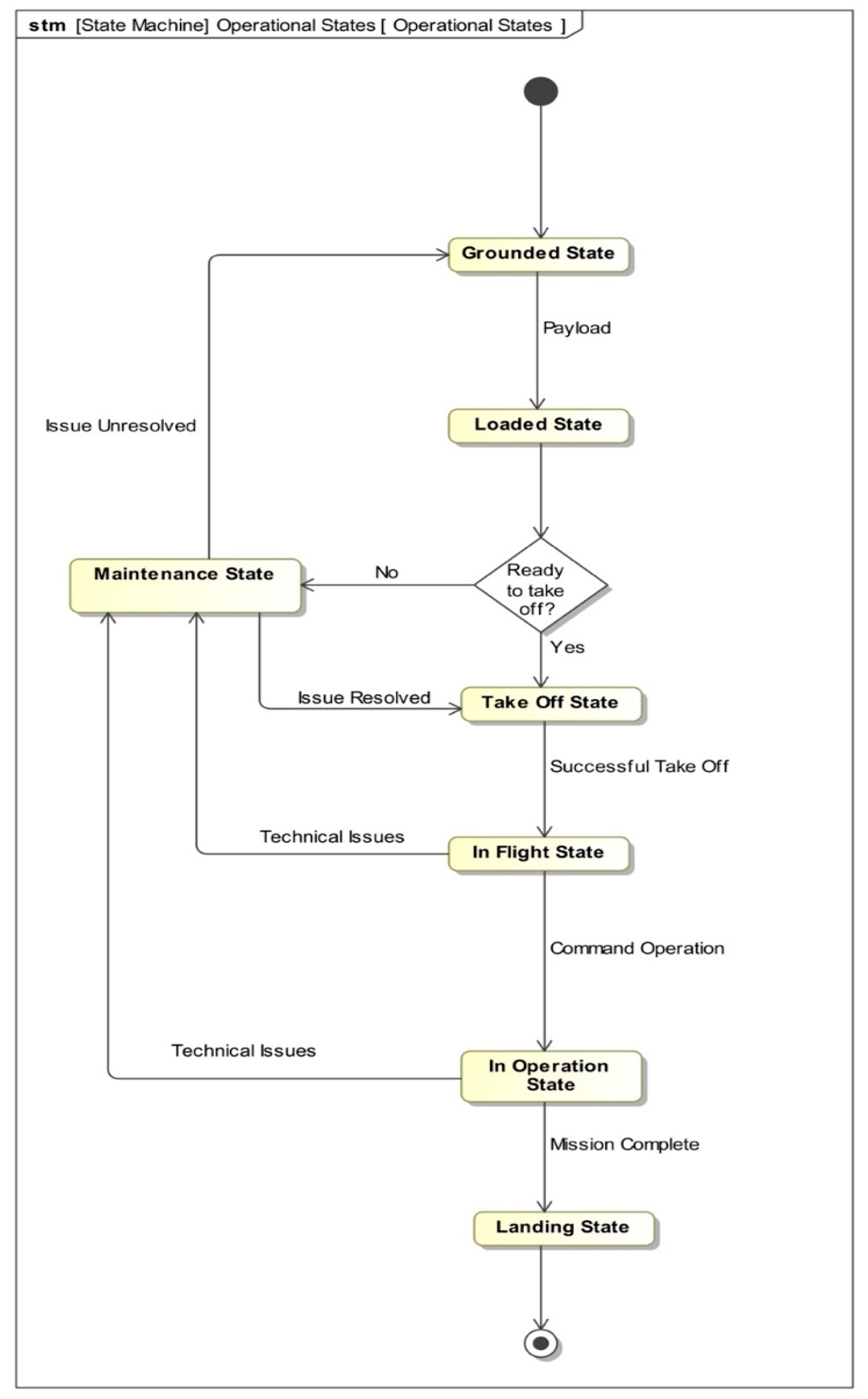
3.3. Development of Behavior Model

Here, the following three kinds of behavior diagrams are developed: use case diagram, activity diagram, and state machine diagram. A use case diagram describes the relationship between the system functions and actors to visualize the use case scenarios [34].
Figure 8 represents the interaction of different actors in the surveillance area with the UAV system using a case diagram.
Figure 9 displays the interaction of internal and external stakeholders of the military sector with the UAV system. Intelligence agencies are responsible for gathering data and conducting enemy surveillance using unmanned aerial vehicles, as well as defense personnel using UAVs for casualty-free attacks, data gathering, and enemy surveillance, as illustrated in Figure 9.
A state machine diagram represents the behavior of a model entity through its transitions between states triggered by events/signals/values. States can have the defined behaviors for any activity such as entry, exit, or do activity. The transition between states can be triggered through guards, too [35].
Figure 10 represents the concept of the operation of UAVs for warfare purposes using a state machine diagram. As seen in Figure 10, the state machine diagram starts with an initial state, which is represented by a solid circle. Following that, an event safety check is accomplished, which triggered the state to take off. The following steps are modeled using the same approach. Finally, reach the final state, which is represented by the concentric circle. In Figure 11, different operational states and triggers of the UAV are represented.
Another type of behavior diagram is used here, an activity diagram is shown in Figure 12 to model the drug calculation procedure of the UAV system. Using an activity diagram, various types of system/part behavior can be modeled with the aid of inputs, outputs, and controls [36]. As part of an activity diagram, it is also possible to depict how the inputs are transformed into outputs, as well as using actions, controls, data flows, and swimming lanes [37].
Generally, the activity diagram starts with an initial node to start of an activity, which is similar to a solid circle, as illustrated in Figure 12. Following this, the flow of data is directed to a fork node that appears as a line segment, and the fork node splits the input flow into two parallel streams, which are directed to two “actions” that are displayed as rectangles with round corners. Flows are directed through various actions for the accomplishment of various tasks, and finally, a node is used to stop the flow of the activity.

4. Executable SysML Simulation

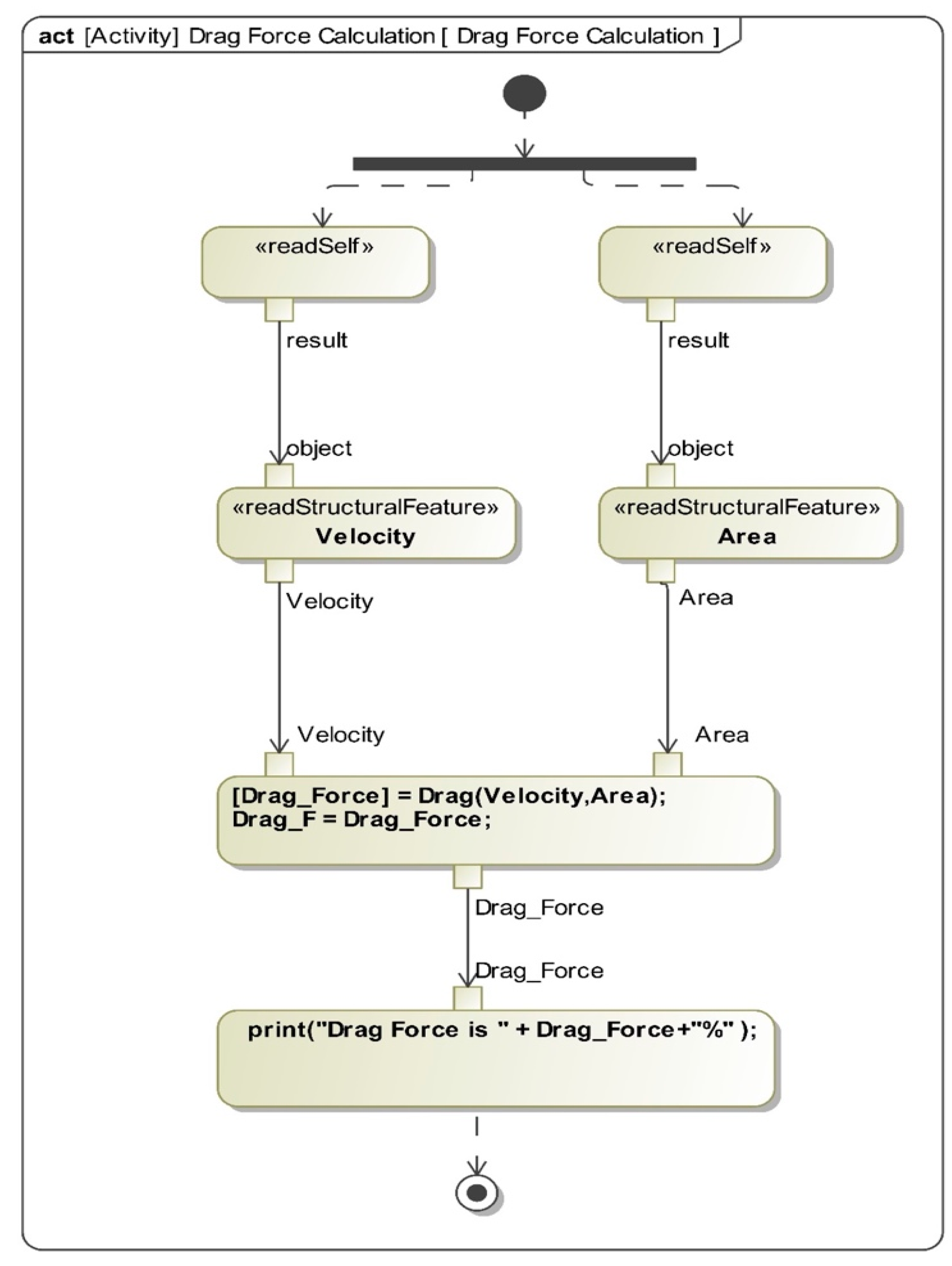
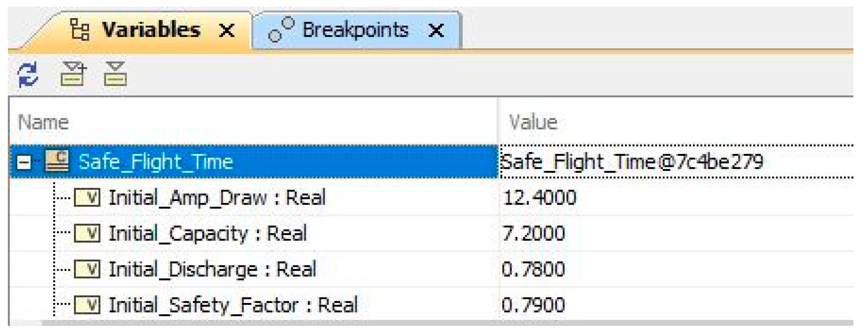
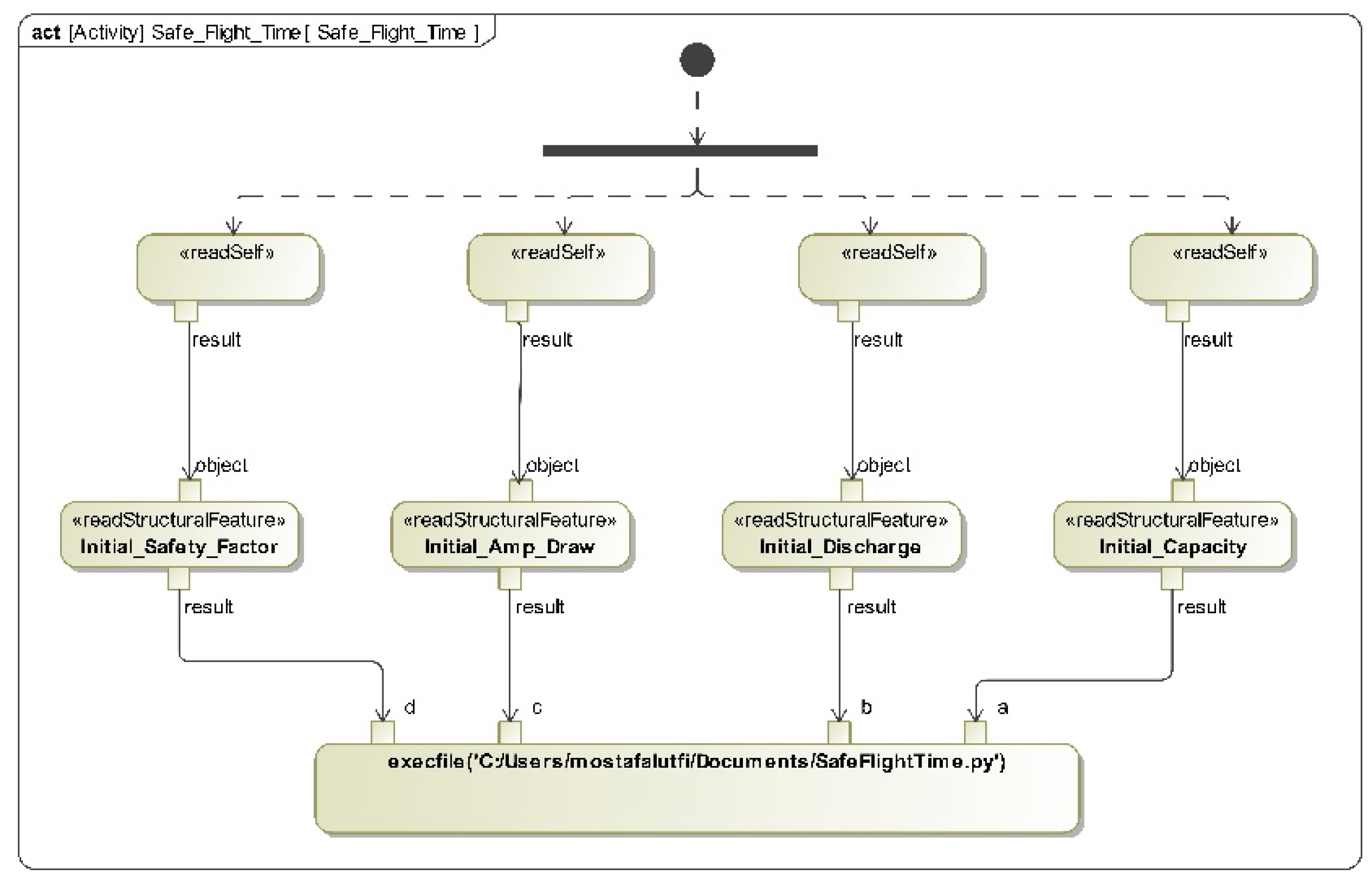
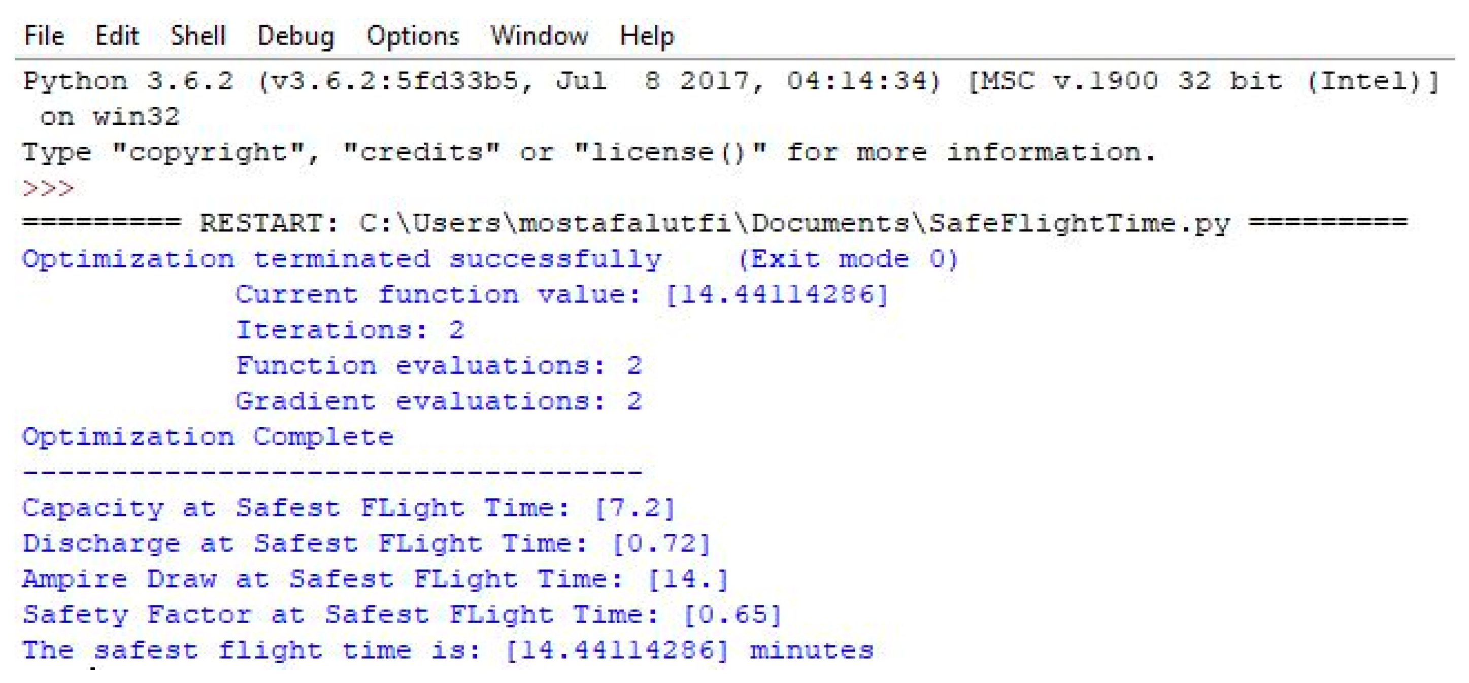
4.1. Execution through Activity Diagram

The activity diagram (see Figure 12) includes opaque action, which facilitates the executability of the model to calculate drag force. A separate MATLAB function was embedded inside the opaque action to make the diagram executable. The <<readStructuralFeature>>stereotype enables reading the inputs of area and velocity from the model. Users can change the values before running the simulation inside the cameo simulation toolkit (CST) (see Figure 13). The expected output for the simulation is the drag force which is indicated by the empty Drag_F value property.
While running the simulation, actions change colors based on their execution timing- green indicates executed before, yellow indicates immediately executed, and red indicates currently being executed (See Figure 14). After running the simulation, the opaque action forwards the inputs to the embedded MATLAB function in order to calculate the drag force. The function output is then returned to the SysML model and assigned to the “Drag_F” value property. Finally, the drag force is shown in the simulation console by printing the output Drag_F value property, as illustrated in Figure 15.
As it is apparent from Figure 15, the calculated drag force (990 N) is less than the value specified in Functional Requirement-7 (See Figure 1). Hence, using the opaque action and CST tool, it was possible to incorporate MATLAB simulation within the SysML model and perform requirements verification based on the design parameters defined in the model.
Opaque actions in activity diagram can be used to call supported scripting files from the local computer. This approach is used to integrate the open-source multidisciplinary design analysis and optimization tool (OpenMDAO) developed by NASA into the SysML model [38]. OpenMDAO tool was imported as a package into the Python environment. Then, in the Python scripting environment a simple “safest drone flight time optimization problem” was formulated followed by OpenMDAO solution mechanics (See Figure 16).
The optimization problem was formulated as follows: Safest Flight Time (min.) = ((Battery Capacity (Ah) × Discharge Rate) × 60 × Safety Factor)/Current Draw of UAV (Amps); constraints and design variables were defined within the script function. The initial values needed to run the OpenMDAO script were provided by CST by reading the initial values defined within the model using value property.
The location of the SafeFlightTime.py function script was provided in the body of the opaque action. The input to the Python script function were the values defined in Figure 17 in order to run the script. Activity diagram with opaque action and <<readStructuralFeature>>stereotyped action items were created to represent the integration mechanism with OpenMDAO-enabled Python scripting environment (see Figure 18). The output generated by the above script was visible in the CST console (Figure 19) to obtain the Safest Flight Time value (as calculated by the OpenMDAO tool).
Figure 20 shows the optimization results obtained in the Python environment as well and hence confirms the integration the OpenMDAO tool with the CST.

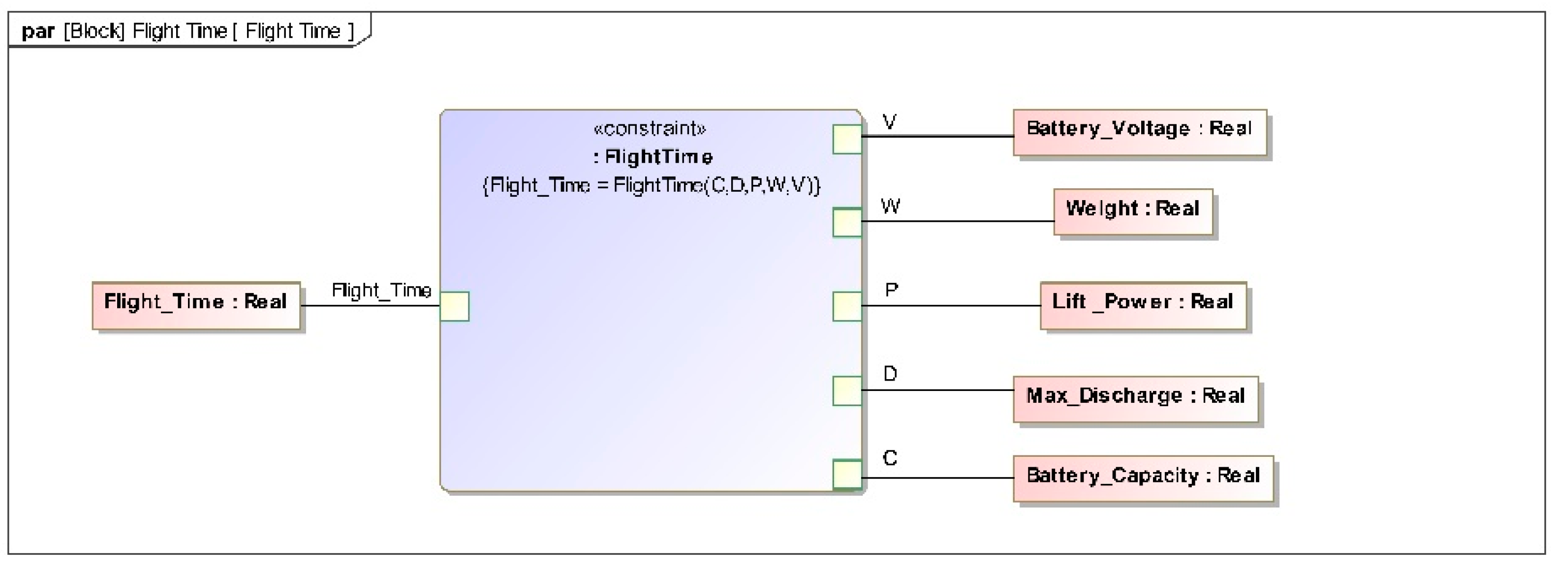
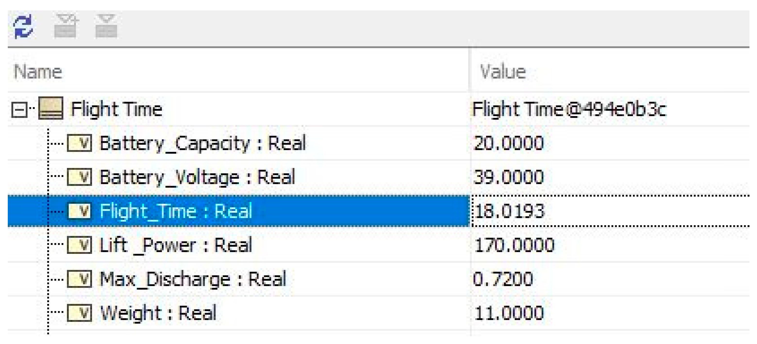
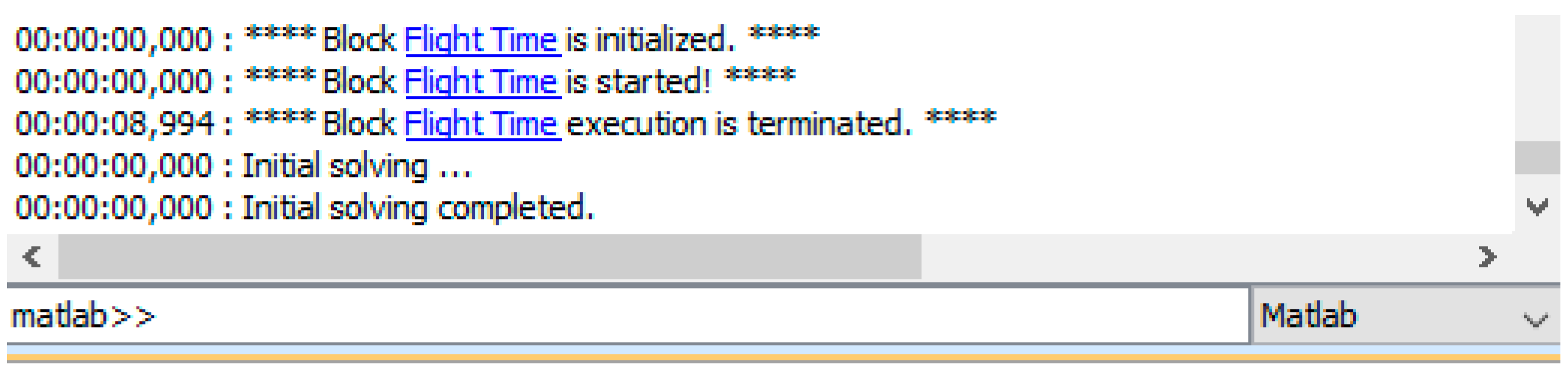
4.2. Execution through Parametric Diagram

For simple SysML models, an activity diagram is a highly effective way of showing the mechanism of the calculations and enabling script integrations [39]. While executing complex system models, the use of the parametric diagram is a more proficient way of dealing with a high volume of data and calculations as compared activity diagram. Although the parametric diagram in CSM cannot incorporate all types of scripting languages supported by the activity diagram. However, it enables easy drag and drop capability of MATLAB scripts into the parametric diagram as a constraint block. So, we used the FlightTime MATLAB function to calculate the drone flight time, which takes the Battery_Voltage, Weight, Lift_Power, Maximum_Discharge, and Battery_Capacity as inputs (see Figure 21).
The output of the function is Flight_Time as demonstrated in Figure 22, which is returned to the CST tool from MATLAB execution. As you can see in the CST console in Figure 23, the Flight_Time value property got populated based on the calculations performed within the MATLAB script.
By implementing the proposed executable simulation methodologies demonstrated above, the static diagrams can be brought to life. In addition to that, using those in-model simulation approaches, the time and effort needed to run simulation results separately will be reduced.

5. Discussion

This study designed the complex system of UAVs using the model-based systems engineering (MBSE) approach. This study utilizes four pillars of SysML, which are structural, behavior, requirements, and parametric aspect. Here, different SysML models, structural, behavior, requirements, and parametric model is used to represent the various design aspect of the UAV system. The structural model used a block definition diagram (BDD), representing the different elements and interrelationships between UAV systems. An internal block definition diagram is used, which represents the interaction and information flow between the elements of UAV systems. This study utilizes a use case diagram that describes the responsibility of external and internal stakeholders of the system to provide a summary of the capabilities of the UAV systems. In addition, this work describes the concept of operation of UAVs in military warfare and the operational states of UAVs using state machine diagrams to illustrate the changes in state and the actions taken by a UAVs systems or subcomponents when interacting with external events. Moreover, this work uses an activity diagram to represent the movement of data and commands between the activities of drag force calculation in UAV systems. As part of this study, we used a requirement diagram to represent the requirements of the UAV system as well as the traceability of the requirements and their annotations. More precisely, a requirement table was developed to define the functional requirements of UAV systems. Finally, a parametric diagram illustrates different constraints of UAV flight time and paves an efficient way to calculate a large amount of data to help engineering examinations. Integrating MATLAB execution with a parametric diagram will facilitate efficient model execution and design/performance calculations. Similar MATLAB integration for a different design parameter of the UAV was performed with the activity diagram to demonstrate the different integration opportunities for comparison. Additionally, the OpenMDAO tool was integrated with the SysML model through the activity diagram without using any custom COTS integration tools.
An important benefit of this study is that it enables users to better understand and design the complex system of UAVs; in addition, it enables users to gain a better understanding of the information flow, the system requirements, and the interaction between the various actors. This study allows users to manage UAV systems more efficiently and improves safety, protection, and reduces human error.

6. Implication of the Study

This study implements the SysML in UAV to provide a sound understanding of UAVs complicated systems. The implication of this work is the following:
  • The study demonstrated the efficacy and extensibility of the model-based system engineering approach in the context of UAV system architecture, behavior, and requirements;
  • UAV systems designed with the SysML diagram described in this study will help the user to better understand the system and will allow for future upgrades, which might be time- and cost-effective. An example of this is the state machine diagram that describes the concept of the operation of a UAV in a military environment. This will aid the users in grasping a clearer understanding of the procedure and will motivate them to use the UAV system and the method of operation;
  • With the MBSE approach described in this study, users of UAVs can continuously monitor the performance of the system. The simulation that has been applied to the activity diagram can also analyze the design parameters of the UAV system. In addition to that, integration of the OpenMDAO tool with the SysML model through the activity diagram was developed without any use of custom COTS integration tools. Finally, the integration of MATLAB execution with a parametric diagram will facilitate efficient model execution and design/performance calculations for complex systems.

7. Conclusions

Since UAVs are increasingly being deployed in everyday applications, it is imperative that practitioners ensure the safety and reliability of the UAV systems. An unmanned aerial vehicle (UAV) is considered to be a complex system with many subsystems, complex technology, and interrelationships that require communication. It is beneficial to use MBSE as a method to improve the design and management of UAV architecture in order to enhance safety measures and minimize man-made errors. MBSE provides many benefits to a UAV system, such as quicker design times, lower costs, fewer errors, and higher traceability. The research contributes to theory, methodology, and application. From a methodological standpoint, this study is useful in illustrating step-by-step how SysML can be applied to the various aspects of UAVs. On a practical level, this study provides a standard design for UAVs based on modeling. There are some works in the literature that design UAVs systems using MBSE, but none of these used simulations to evaluate model parameters against functional requirements defined in the SysML model. So, this study fills this gap in the literature by enabling simulation within the SysML model through interoperability with external simulation tools, i.e., MATLAB, OpenMDAO, and Python. Thus, the SysML model can be used solely to evaluate the design/architectural parameters in the early phases of the UAVs system lifecycle, which will reduce the cost and effort required in the later phases. This work is also subject to some limitations including (i) the scale of the simulation computations (Matlab and openMDAO) was not substantial; only integration capability was highlighted, (ii) the drone model in this example was created using a “black box” method and overall SysML model has been extended to level 3. In the future, this work can be expanded by including detailed components of a UAV system. Another way to expand the work in the future is by incorporating more complex OpenMDAO and Matlab calculations, including component-level design alternatives evaluation considering the fact that the integration’s fundamental functioning will not change.

Author Contributions

Conceptualization, N.U.I.H. and M.L.; methodology, N.U.I.H. and M.L.; software, M.L. and N.U.I.H.; validation, N.U.I.H., M.L., D.C. and A.A.; formal analysis, N.U.I.H., M.L. and I.A.; investigation, N.U.I.H., M.L. and I.A.; resources, N.U.I.H., M.L. and I.A.; data curation, N.U.I.H., M.L. and I.A.; writing—original draft preparation, N.U.I.H., M.L. and I.A.; writing—review and editing, N.U.I.H., M.L., A.A. and D.C.; visualization, N.U.I.H., M.L., I.A., A.A. and D.C.; supervision, N.U.I.H. and M.L.; project administration, N.U.I.H. All authors have read and agreed to the published version of the manuscript.

Funding

This research received no external funding.

Institutional Review Board Statement

Not Applicable.

Informed Consent Statement

Not Applicable.

Data Availability Statement

Data sharing not applicable—no new data generated data sharing does not apply to this article as no new data were created or analyzed in this study.

Conflicts of Interest

Authors do not have any potential conflict.

References

  1. Pigatto, D.F.; Gonçalves, L.; Pinto, A.S.R.; Roberto, G.F.; Rodrigues Filho, J.F.; Branco, K.R.L.J.C. HAMSTER-Healthy, mobility and security-based data communication architecture for Unmanned Aircraft Systems. In Proceedings of the 2014 International Conference on Unmanned Aircraft Systems (ICUAS), Orlando, FL, USA, 27–30 May 2014; pp. 52–63. [Google Scholar]
  2. Krichen, L.; Fourati, M.; Fourati, L.C. Communication architecture for unmanned aerial vehicle system. In Proceedings of the International Conference on Ad-Hoc Networks and Wireless, St Malo, France, 5–7 September 2018; pp. 213–225. [Google Scholar]
  3. Peng, S.; Zhou, Y.; Cao, L.; Yu, S.; Niu, J.; Jia, W. Influence analysis in social networks: A survey. J. Netw. Comput. Appl. 2018, 106, 17–32. [Google Scholar] [CrossRef]
  4. Al-Fedaghi, S.S.; Al-Fadhli, J. Modeling an unmanned aerial vehicle as a thinging machine. In Proceedings of the 2019 5th International Conference on Control, Automation and Robotics (ICCAR), Beijing, China, 19–22 April 2019; pp. 758–765. [Google Scholar]
  5. Hart, L.E. Introduction to model-based system engineering (MBSE) and SysML. In Delaware Valley INCOSE Chapter Meeting; Ramblewood Country Club: Mount Laurel, NJ, USA, 2015. [Google Scholar]
  6. Elakramine, F.; Jaradat, R.; Hossain, N.U.I.; Banghart, M.; Kerr, C.; El Amrani, S. Applying Systems Modeling Language in an Aviation Maintenance System. IEEE Trans. Eng. Manag. 2021, 69, 758–765. [Google Scholar] [CrossRef]
  7. Dzielski, J.; Blackburn, M. Implementing a Decision Framework in SysML Integrating MDAO Tools. INSIGHT 2018, 21, 15–19. [Google Scholar] [CrossRef]
  8. Apvrille, L.; de Saqui-Sannes, P.; Vingerhoeds, R. An educational case study of using sysml and ttool for unmanned aerial vehicles design. IEEE J. Miniat. Air Space Syst. 2020, 1, 117–129. [Google Scholar] [CrossRef]
  9. Steurer, M.; Morozov, A.; Janschek, K.; Neitzke, K.P. SysML-based profile for dependable UAV design. IFAC-PapersOnLine 2018, 51, 1067–1074. [Google Scholar] [CrossRef]
  10. Xing-hua, L.; Yun-feng, C. Design of UAV flight control system virtual prototype using rhapsody and simulink. In Proceedings of the 2010 International Conference On Computer Design and Applications, Qinhuangdao, China, 25–27 June 2010; pp. V3–V4. [Google Scholar]
  11. Queiroz, P.; Braga, R. Combining MARTE-UML, SysML and CVL to build unmanned aerial vehicles. In Proceedings of the Ninth International Conference on Software Engineering Advances, Nice, France, October 2014; pp. 334–340. [Google Scholar]
  12. Hernandez, T.R. Modeling Situation Awareness in a UAV Scenario Using SysML. Theses and Dissertations. 2021. Available online: https://scholar.afit.edu/etd/5039 (accessed on 15 October 2022).
  13. Aljehani, M.; Inoue, M.; Yokemura, T. Particle Swarm Optimization Algorithm Presented in SysML and Applied in Multi-UAV System. In Proceedings of the 2021 IEEE International Conference on Consumer Electronics (ICCE), Las Vegas, NV, USA, 10–12 January 2021; pp. 1–4. [Google Scholar]
  14. MacCarthy, J. The Drone System I: Context-Level Architecture. In Proceedings of the INCOSE International Symposium, Williams Building, College Park, MD, USA; 2019; pp. 1174–1184. [Google Scholar]
  15. Leserf, P.; De Saqui-Sannes, P.; Hugues, J. Trade-off analysis for SysML models using decision points and CSPs. Softw. Syst. Model. 2019, 18, 3265–3281. [Google Scholar] [CrossRef] [Green Version]
  16. Specking, E.; Parnell, G.; Pohl, E.; Buchanan, R. Early Design Space Exploration with Model-Based System Engineering and Set-Based Design. Systems 2018, 6, 45. [Google Scholar] [CrossRef] [Green Version]
  17. Aïello, O.; Kandel, D.S.D.R.; Chaudemar, J.C.; Poitou, O.; De Saqui-Sannes, P. Populating MBSE models from MDAO analysis. In Proceedings of the 2021 IEEE International Symposium on Systems Engineering (ISSE), Vienna, Austria, 13 September–13 October 2021; pp. 1–8. [Google Scholar]
  18. Srivastava, A. Tradespace Exploration of a UAV Conceptual Design Using Model-Based Systems Engineering. Ph.D. Thesis, Clemson University, Clemson, SC, USA, 2021. [Google Scholar]
  19. Aloui, K.; Hammadi, M.; Guizani, A.; Haddar, M.; Soriano, T. A new SysML Model for UAV Swarm Modeling: UavSwarmML. In Proceedings of the 2022 IEEE International Systems Conference (SysCon), Montreal, QC, Canada, 25–28 April 2022; pp. 1–8. [Google Scholar]
  20. Wang, Y.; Sun, Q.; Wang, M.; Zhang, Y. The Requirement Traceable Modeling Method and Application of UAV Command System-of-systems Based on SysML. In Proceedings of the 2021 IEEE International Conference on Unmanned Systems (ICUS), Beijing, China, 15–17 October 2021; pp. 767–772. [Google Scholar]
  21. Goodchild, A.; Toy, J. Delivery by drone: An evaluation of unmanned aerial vehicle technology in reducing CO2 emissions in the delivery service industry. Transp. Res. Part D Transp. Environ. 2018, 61, 58–67. [Google Scholar] [CrossRef]
  22. Voss, W.G. Privacy law implications of the use of drones for security and justice purposes. Int. J. Liabil. Sci. Enq. 2013, 6, 171–192. [Google Scholar] [CrossRef]
  23. Boucher, P. Domesticating the drone: The demilitarisation of unmanned aircraft for civil markets. Sci. Eng. Ethics 2015, 21, 1393–1412. [Google Scholar] [CrossRef] [PubMed]
  24. Hause, M. The SysML modelling language. In Proceedings of the Fifteenth European Systems Engineering Conference, Cheltenham, UK, 18–20 September 2006; pp. 1–12. [Google Scholar]
  25. Bouquet, F.; Gauthier, J.-M.; Hammad, A.; Peureux, F. Transformation of SysML structure diagrams to VHDL-AMS. In Proceedings of the 2012 Second Workshop on Design, Control and Software Implementation for Distributed MEMS, Besancon, France; pp. 74–81.
  26. Hause, M.C.; Thom, F. An integrated MDA approach with SysML and UML. In Proceedings of the 13th IEEE International Conference on Engineering of Complex Computer Systems (iceccs 2008), Belfast, UK, 31 March–3 April 2008; pp. 249–254. [Google Scholar]
  27. Friedenthal, S.; Moore, A.; Steiner, R. A Practical Guide to SysML: The Systems Modeling Language; Morgan Kaufmann: Burlington, MA, USA, 2014. [Google Scholar]
  28. dos Santos Soares, M.; Vrancken, J. Requirements specification and modeling through SysML. In Proceedings of the 2007 IEEE International Conference on Systems, Man and Cybernetics; pp. 1735–1740.
  29. Buchmann, T.; Dotor, A.; Westfechtel, B. Model-driven software engineering: Concepts and tools for modeling-in-the-large with package diagrams. Comput. Sci. Res. Dev. 2014, 29, 73–93. [Google Scholar] [CrossRef]
  30. Goto, T.; Kirishima, T.; Nishino, T.; Yaku, T.; Tsuchida, K. Generation of UML package diagrams based on an attribute graph grammar. J. Comput. Sci. 2014, 5, 606–615. [Google Scholar] [CrossRef]
  31. Arifin, H.H.; Ong, H.K.R.; Daengdej, J.; Novita, D. Encoding technique of genetic algorithms for block definition diagram using OMG SysML™ notations. In Proceedings of the INCOSE International Symposium; pp. 218–232.
  32. Pustina, L.; Schwarzer, S.; Martini, P.; Muurinen, J.; Salomaki, A. A methodology for performance predictions of future arm systems modelled in uml. In Proceedings of the 2008 2nd Annual IEEE Systems Conference, Montreal, QC, Canada, 7–10 April 2008; pp. 1–8. [Google Scholar]
  33. Mhenni, F.; Nguyen, N.; Choley, J.-Y. Automatic fault tree generation from SysML system models. In Proceedings of the 2014 IEEE/ASME International Conference on Advanced Intelligent Mechatronics, Besacon, France, 8–11 July 2014; pp. 715–720. [Google Scholar]
  34. Fauzan, R.; Siahaan, D.; Rochimah, S.; Triandini, E. Use case diagram similarity measurement: A new approach. In Proceedings of the 2019 12th International Conference on Information & Communication Technology and System (ICTS), Surabaya, Indonesia, 18 July 2019; pp. 3–7. [Google Scholar]
  35. Baouya, A.; Bennouar, D.; Mohamed, O.A.; Ouchani, S. A probabilistic and timed verification approach of SysML state machine diagram. In Proceedings of the 2015 12th International Symposium on Programming and Systems (ISPS), Algiers, Algeria, 28–30 April 2015; pp. 1–9. [Google Scholar]
  36. Jarraya, Y.; Soeanu, A.; Debbabi, M.; Hassaine, F. Automatic verification and performance analysis of time-constrained sysml activity diagrams. In Proceedings of the 14th Annual IEEE International Conference and Workshops on the Engineering of Computer-Based Systems (ECBS’07), Tucson, AZ, USA, 26–29 March 2007; pp. 515–522. [Google Scholar]
  37. Rahim, M.; Hammad, A.; Boukala-Ioualalen, M. Towards the formal verification of sysml specifications: Translation of activity diagrams into modular petri nets. In Proceedings of the 2015 3rd International Conference on Applied Computing and Information Technology/2nd International Conference on Computational Science and Intelligence, Okayama, Japan, 12–16 July 2015; pp. 509–516. [Google Scholar]
  38. Gray, J.S.; Hwang, J.T.; Martins, J.R.R.A.; Moore, K.T.; Naylor, B.A. OpenMDAO: An Open-Source Framework for Multidisciplinary Design, Analysis, and Optimization. Struct. Multidiscip. Optim. 2019, 59, 1075–1104. [Google Scholar] [CrossRef]
  39. Kerr, C.; Jaradat, R.; Hossain, N.U.I. Battlefield mapping by an unmanned aerial vehicle swarm: Applied systems engineering processes and architectural considerations from system of systems. IEEE Access 2020, 8, 20892–20903. [Google Scholar] [CrossRef]
Figure 1. Representation of a requirement diagram.
Systems 10 00264 g001
Figure 2. Representation of a requirement table showing the functional requirements.
Systems 10 00264 g002
Figure 3. Package diagram of model organization.
Systems 10 00264 g003
Figure 4. Block definition diagram (BDD) of unmanned aerial vehicle (UAV).
Systems 10 00264 g004
Figure 5. BDD of Air vehicle system (AVS).
Systems 10 00264 g005
Figure 6. BDD of the payload subsystem.
Systems 10 00264 g006
Figure 7. Internal block definition diagram (IBD) of UAV.
Systems 10 00264 g007
Figure 8. Use case diagram of UAV for surveillance purpose.
Systems 10 00264 g008
Figure 9. Use case diagram of UAV for military application.
Systems 10 00264 g009
Figure 10. State machine diagram of the concept of operation of UAV in military warfare.
Systems 10 00264 g010
Figure 11. State machine diagram of the operational states of UAVs.
Systems 10 00264 g011
Figure 12. Activity diagram of drag force calculation of UAVs.
Systems 10 00264 g012
Figure 13. Before simulation run.
Systems 10 00264 g013
Figure 14. Execution of actions shown by color.
Systems 10 00264 g014
Figure 15. Printing drag force in the simulation console.
Systems 10 00264 g015
Figure 16. OpenMDAO script snippets.
Systems 10 00264 g016
Figure 17. Defined input parameters in the Cameo Simulation Toolkit environment.
Systems 10 00264 g017
Figure 18. Activity diagram enabling the integration with the OpenMDAO script.
Systems 10 00264 g018
Figure 19. Execution results shown in the CST console.
Systems 10 00264 g019
Figure 20. OpenMDAO solutions in the Python environment.
Systems 10 00264 g020
Figure 21. Parametric diagram showing the binding parameters and script function as constraint.
Systems 10 00264 g021
Figure 22. Flight time value property populated by the execution of the MATLAB script.
Systems 10 00264 g022
Figure 23. CST simulation console showing the environment as Matlab.
Systems 10 00264 g023
Table 1. Application of SysML in UAV literature review.
AuthorsApproachApplication Area and Findings
Apvrille, Sannes [8]MBSE approach includes architectural, behavior, and requirement modelProviding design of the architecture of UAVs.
Steurer, Morozov [9]Dual-graph error propagation model (DEPM) and SysML and the technique for converting the SysML model to the DEPMStudying the UAV dependability profile and providing the technique for converting the SysML model to the DEPM.
Xing-hua and Yun-feng [10]Rhapsody and SimulinkProviding a technique of UAVs flight control systems virtual design.
Queiroz and Braga [11]Combination of product line engineering (PLE) and model-driven engineering (MDE)Providing a method for producing family models of UAV.
Hernandez [12]Integration of No Magic’s Cameo Systems Modeler and external SA analysis toolsTo monitor the information flow that helps operator situation awareness (SA), and the results of the study showed that it is feasible to measure the elements of information acquired from the environment and transmitted to the operator via the UAS.
Aljehani, Inoue [13]A particle swarm optimization (PSO) method using a SysML activity diagramDeploying the method to a multi-UAV with chosen airframes and the study’s findings revealed varied fitness values and the optimal site for various UAV airframes.
MacCarthy [14]SysML structural and behavioral diagramsDescribing reference design of the drone system and identifying type of the analysis needed for designing a system.
Dzielski and Blackburn [7]A SysML approach using a multi-dimensional design and optimization (MDAO) toolPresenting a decision framework
and implementing it to a hypothetical drone and also concluded that it is feasible.
Leserf, de Saqui-Sannes [15]MBSE, Sysml, Papyrus, EclipseTrade-off analysis in multi-core UAVs and described that it is feasible to create the problem description file to use a SysML extension and their plug-in
Specking, Parnell [16]Combination of set-based design (SBD) and MBSEAn integrated framework for trade space exploration (TSE)
Aïello, Kandel [17]Multidisciplinary design analysis and optimization (MDAO) and MBSE On battery usages of UAVs and provided a way to increase self-confidence in some model values, increase self-confidence in the accomplishment of requirements, and refine some requirements values more precisely
Srivastava [18]MBSEThe theoretical design of UAVs and provided a basis for formalizing models frequently used in conceptual airplanes, leading to a more structured framework for the models to be implemented, and lowering disparity and errors.
Aloui, Hammadi [19]MBSE, SysML, domain-specific language (DSL), robot operating system (ROS)Designing an efficient swarm of UAVs
Wang, Sun [20]SysMLTo solve the issue of requirements tracing for adaption strategies underneath the circumstances of significant demands, intricate linkages, and rapid changes in the UAV command structure and made it easier to quickly develop a model of the command system-of-systems capacity needs.
Publisher’s Note: MDPI stays neutral with regard to jurisdictional claims in published maps and institutional affiliations.

