1. Introduction
Integrating structural reinforcement into 3D-printed concrete components remains one of the biggest challenges for additive manufacturing to gain a sustainable foothold in the construction industry. Today, a variety of reinforcement integration strategies using different materials are being investigated worldwide. These range from manual insertion of conventional steel reinforcement into a 3D-printed lost formwork, co-extrusion of short fibers or continuous filaments within the concrete strand, injection of nails and screws to vertically connect layers, to simultaneous additive manufacturing using Wire Arc Additive Manufacturing (WAAM) [
1].
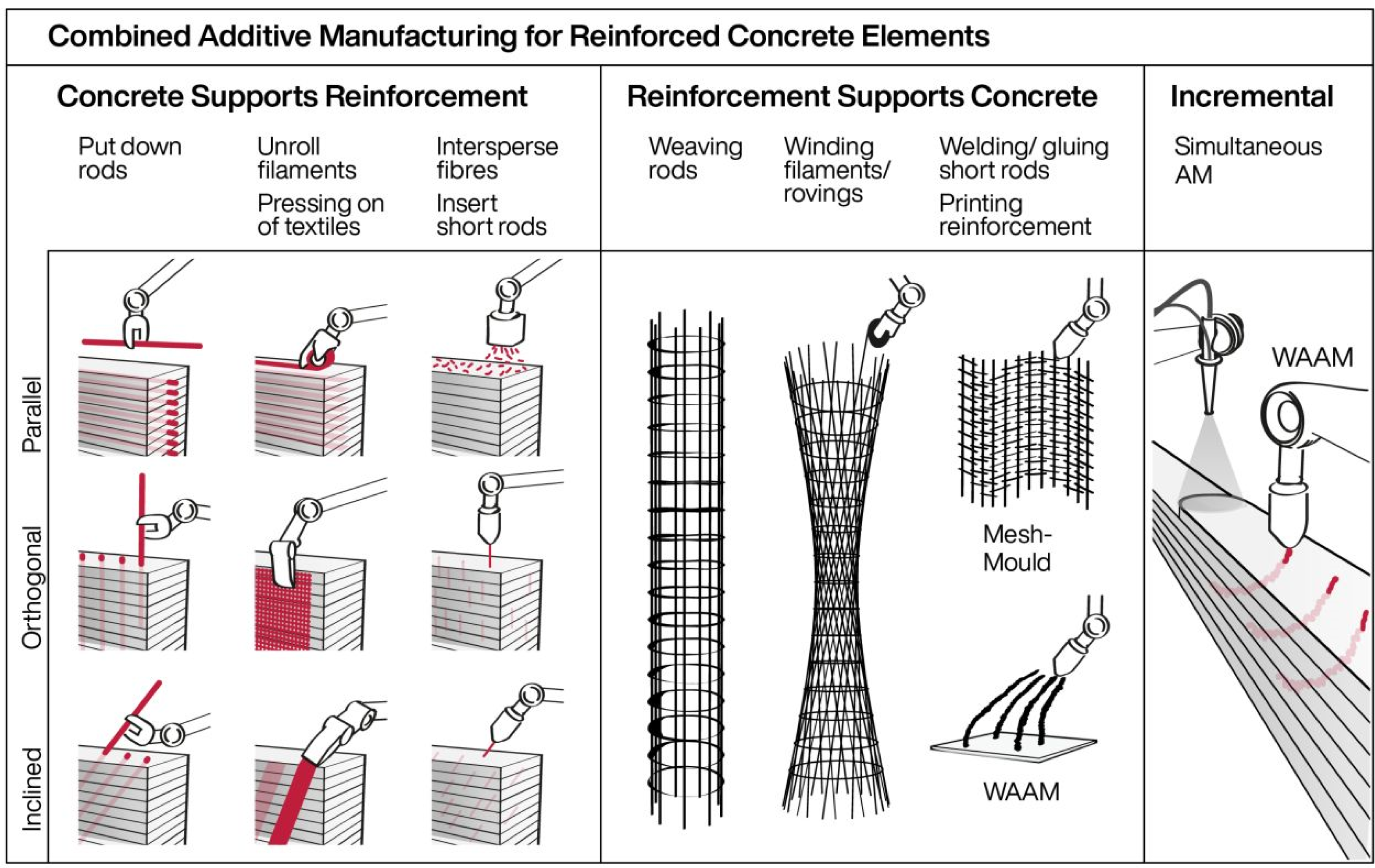
Although these approaches to integrating reinforcement into the additive manufacturing process vary widely, a classification of reinforcement can be used based on its functionality during the additive manufacturing process. This classification approach groups reinforcement into three categories: firstly, “concrete supports reinforcement” (CSR); secondly, the inverse approach, “reinforcement supports concrete” (RSC); and thirdly, incremental processes, where concrete and reinforcement are fabricated almost simultaneously with only a minor time offset. This classification approach is depicted in
Figure 1 and described in more detail by Kloft et al. [
2].
In the first category, “Concrete Supports Reinforcement,” the freshly printed concrete, supports the reinforcement, allowing for accurate placement of the reinforcement without the need for additional rebar stirrups that are commonly used for positioning. The techniques investigated for this purpose include the injection of a short reinforcement orthogonal to the layer orientation, pressing of textile reinforcement into the fresh concrete, and the placement of reinforcing bars between the layers, to name a few. The second category, “Reinforcement Supports Concrete”, inverts this logic. Here the reinforcement is prefabricated and in a subsequent process concrete is printed or sprayed onto the structure. A key feature of this approach is that the reinforcement determines the shape of the final structure and remains in the structure as an integral part.
2. Background
The principle of stay-in-place (SIP) formwork is also a well-known manufacturing method outside of the realm of additive manufacturing in construction. The advantages of this construction method are primarily the efficient, fast, precise, and cost-effective production of prefabricated reinforced components.
The use of reinforcement as a form-giving element for cement-bound building components dates back to the first concrete patents by Joseph-Louis Lambot in the 18th century [
3]. Lambot used flexible wire mesh as a support material to apply cement paste to it, thus counteracting the formation of cracks in the cured cement elements.
A century later, the Italian architect-engineer Pier Luigi Nervi rediscovered this construction method, which had in the meantime been superseded by conventional reinforced concrete construction. Nervi coined the technique “Ferrocement” and developed it further into “Structural Prefabrication”, where semi-finished products were manufactured according to the ferrocement principle as lightweight stay-in-place formwork, and which were then assembled on the construction site and filled with conventional concrete [
4]. A prominent example of this efficient construction method is the Palazzetto dello Sport in Rome [
5].
Nowadays, SIPs can be manufactured not only using metal, but also with other advanced construction materials such as fiber-reinforced polymers (FRP) based on glass or carbon fibre. A good overview of FRP stay-in-place formwork systems for concrete is provided in [
6,
7].
2.1. Preliminary Work
Based on the principles of stay-in-place formwork described above, the Mesh Mould construction system was developed as part of a dissertation at ETH Zurich by the author using advanced robotic technology [
8,
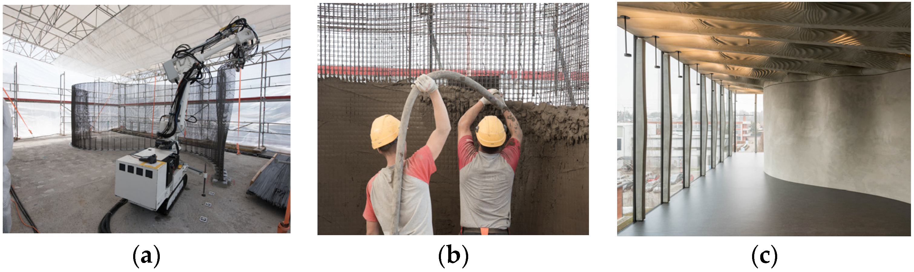
9]. In the Mesh Mould research, a robotically bent steel mesh was used as structural stay-in-place formwork in order to create a slender double-curved wall acting as the main loadbearing element of the DFAB house on Nest (see
Figure 2) [
10,
11]. In this project, a mobile robot fabricated a geometrically complex steel mesh by automatically bending, cutting and welding 8-mm steel rebars in situ, directly on the construction site [
12]. Concreting and surface finishing, however, were performed manually in a subsequent step. One of the challenges regarding the application of the concrete cover is to guarantee a constant cover thickness of 3 cm, providing sufficient protection to avoid corrosion of the steel reinforcement below.
2.2. Textile Concrete Reinforcement
An alternative to the use of corrosive steel reinforcement is the use of textile reinforcement made of continuous glass or carbon fiber. In comparison to steel, textiles display a unique set of features that make them highly interesting for the use in additive manufacturing in construction. Firstly, the corrosion resistance allows to substantially reduce the required concrete cover form from several centimeters to only a few millimeters. This has a profound impact on the total amount of concrete used in a structure, and hence on the embedded energy of a construction. In addition, the components that have to be transported to the construction site are lighter and can therefore be handled with lightweight equipment on the construction site. The second major advantage of using textiles compared to steel reinforcement is the greater flexibility of the material, which makes textile easier to be handled for automation, allowing for a differentiated spatial arrangement, as it is for example necessary for a force-flow oriented layout of the reinforcement. In the context of the multiple possibilities for integrating continuous fibers in the three categories mentioned above, the focus of this project is on the integration of prefabricated fiber reinforcement produced in a robotic winding process, providing a high degree of geometric freedom. As such, the research project sits within the larger context of the Collaborative Research Center TRR277 Additive Manufacturing in Construction [
13] and investigates the integration of prefabricated fiber reinforcement for a range of additive manufacturing processes with concrete, including extrusion and particle bed printing. However, the latter are not described in this paper.
2.3. Use of Continuous Fibers in Digital Fabrication and Additive Manufacturing
The pre-fabrication of freestanding individualized glass- and carbon fiber building components has previously been investigated in architecture mainly for the application of lightweight structures. In various experimental pavilions, researchers of the Institute of Computational Design and Construction (ICD) in Stuttgart demonstrated the potential of “coreless winding” for the fabrication of structurally efficient, lightweight structures [
14,
15,
16].
Also, in combination with concrete, different strategies of using individualized prefabricated fiber meshes are currently investigated: For an experimental pavilion, researchers from University of Innsbruck have combined “coreless winding” with a manual shotcreting process. For this, three columns carrying three inverted umbrellas were prefabricated, shotcrete was applied, and the structure was assembled in place. Depending on the mesh density, the concrete cover gradually varies from solid to porous [
17].
Another approach also based on fiber winding is being investigated within the C
3 research initiative [
18]. Researchers of TU Dresden are exploring the prefabrication of winded carbon fiber meshes as inlays for conventional concrete casting processes. One particularly noteworthy approach within this context is the robot-assisted winding of continuous impregnated carbon fiber roving around a steel frame describing the shape of a wall with openings. After winding, the frame is removed and the reinforcement is placed in a conventional concrete formwork for casting [
19]. In other research projects of the group, the simultaneous co-extrusion of carbon fibers in the printing process is being investigated [
20].
Another approach followed by Block Research Group at ETH Zurich utilizes 3D knitting of technical textiles for fabricating lightweight fabric formworks for thin concrete shell structures [
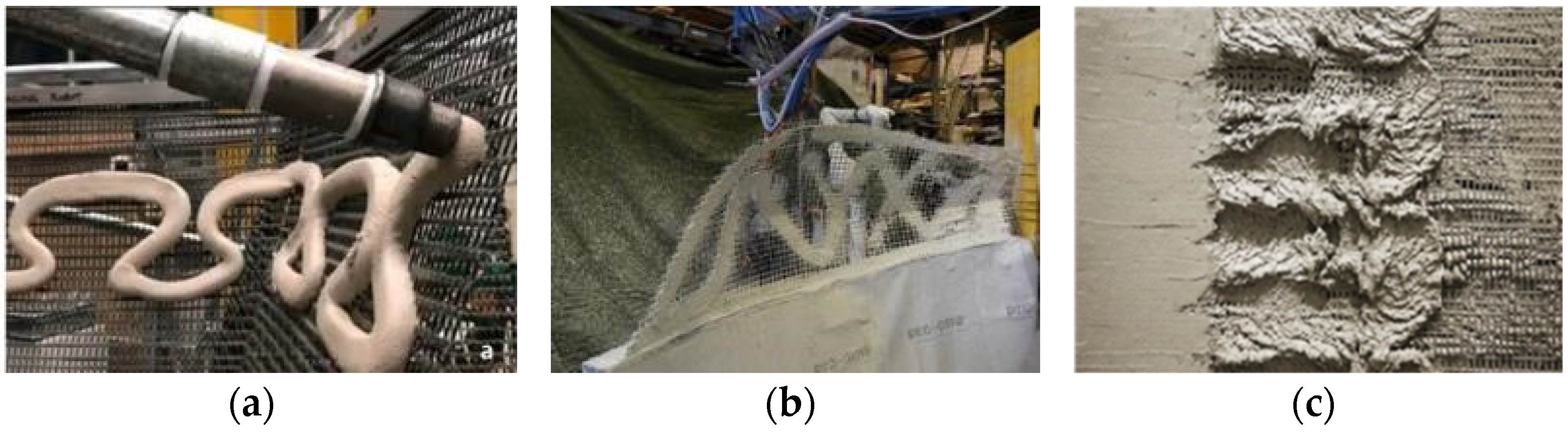
21]. Here, long strips of textiles with integrated pockets for steel cables are knitted on a computer controlled industrial knitting machine. In order for the formwork to stand up and support the fresh concrete, the formwork is tensioned over a support frame before it is subsequently manually covered using a multi-stage shotcrete process. In addition to the use of individualized carbon fiber elements, there are several research projects that use standard carbon fiber mats as a structural stay-in-place formwork system for additive manufacturing processes. One example for “reinforcement supports concrete” is the “SCRIM” approach, where concrete is robotically extruded onto a standard carbon fiber reinforcement mat (see
Figure 3a), [
22]. A similar technique was developed by Gramazio Kohler Research at ETH Zurich using robotically sprayed concrete. In the AeroCrete project, a follow-up to the Mesh Mould research, a robot-assisted spraying process with fiber-reinforced concrete was investigated in order to produce thin shell constructions (see
Figure 3b), [
23]. In
Figure 3c, differently from the previous projects, a concrete core was 3D printed first, and then a standard mat was pressed into the concrete and covered again with a layer of concrete [
24].
3. Dynamic Fiber Winding of Concrete Reinforcement Structures
3.1. Process Requirements
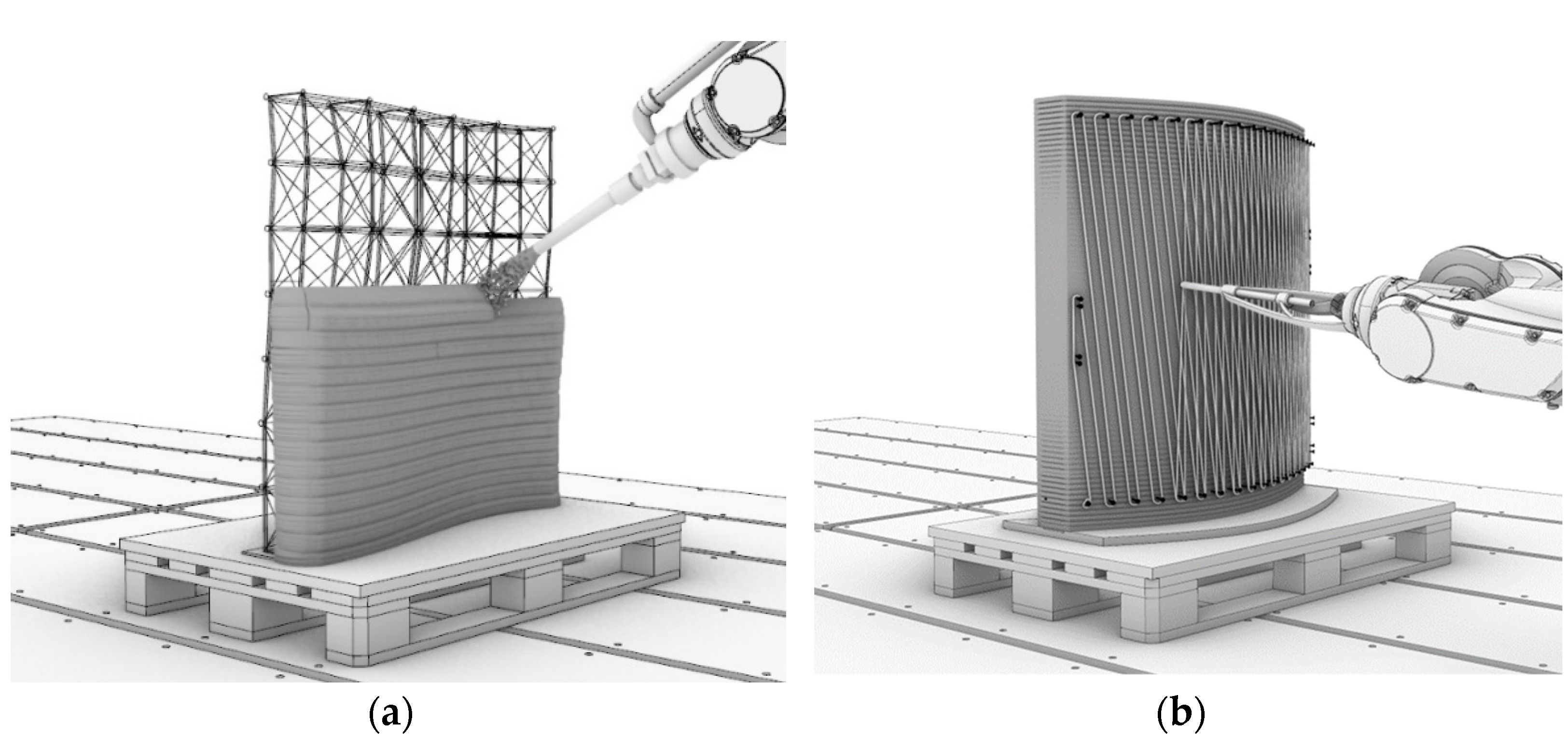
This paper is part of a research project aimed at developing a new method for the automated integration of textile reinforcement for additive manufacturing with concrete, using Shotcrete 3D Printing (SC3DP). SC3DP is an additive manufacturing process developed at the TU Braunschweig and is particularly suitable for this process, as the shotcrete also adheres to vertical surfaces [
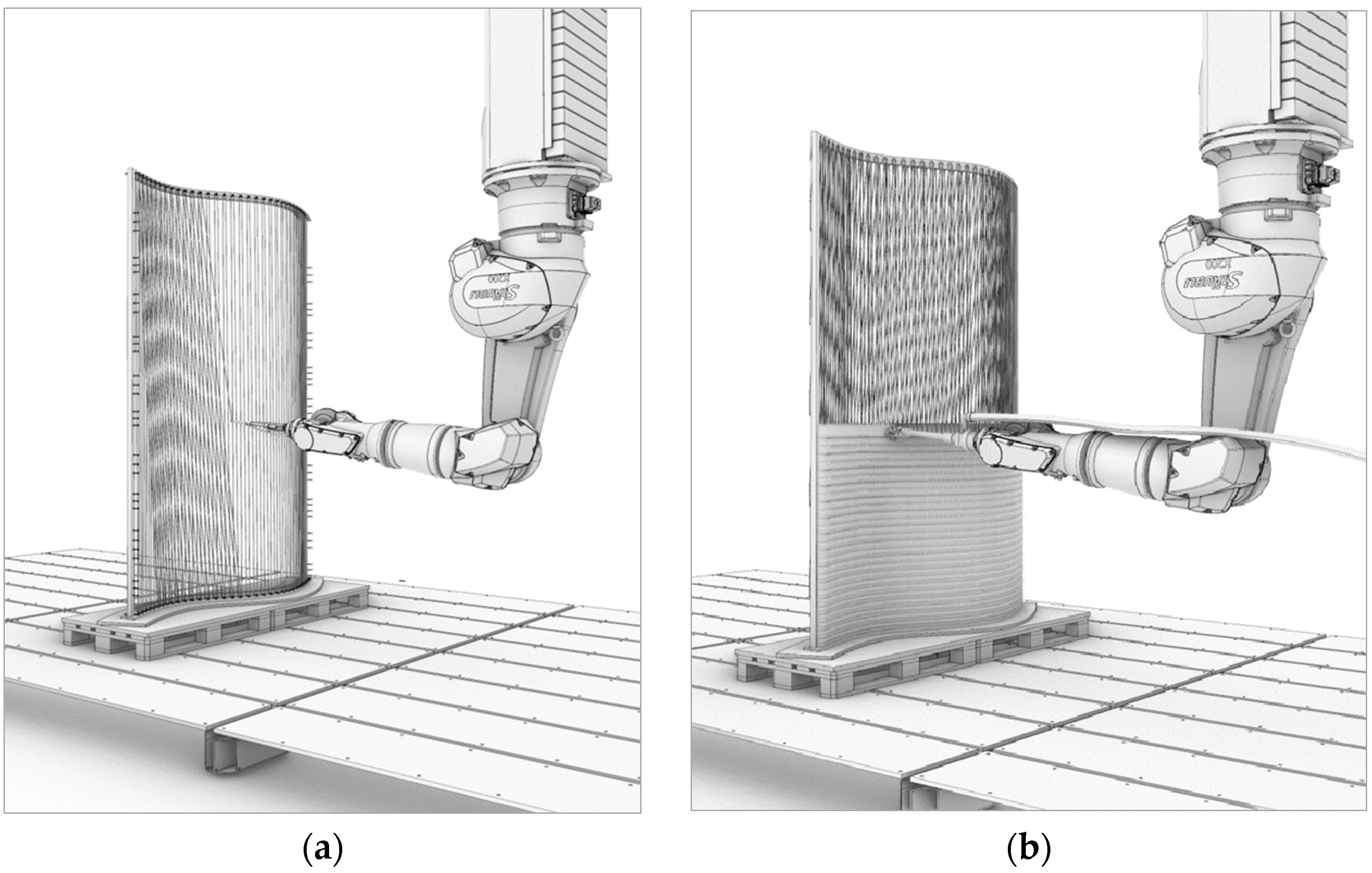
25]. As such, the strategy of this project includes the prefabrication of freestanding fiber reinforcement meshes by a dynamic fiber winding process such that it subsequently enables the automated direct deposition of concrete onto the meshes as well as the automated surface finishing (see
Figure 4). According to the “reinforcement supports concrete” definition above, the research follows the overall concept that a prefabricated, individualized fiber reinforcement structure functions both as a shaping and reinforcing element for the subsequent automated concreting process. Depending on the project requirements, the production of the reinforcement structures as well as the concreting can be realized either by prefabrication in the factory, prefabrication in a mobile on-site factory, or directly in situ using mobile robots, hence allowing for a high flexibility in terms of element geometry, size, and scheduling.
3.2. Technical Challenges: Increasing Fiber-Concrete Bonding via Core Winding
Similar to conventional ribbed steel reinforcement, it is necessary to establish a sufficient mechanical bond between the FRP reinforcement and the concrete. For FRP rebars, special surface treatments are used to increase their bond with concrete [
26,
27,
28].
One common method is to wrap an additional fiber around a fiber roving, which is produced by a pultrusion process. This method significantly increases the mechanical interlocking of the rebar with the cementitious matrix while also preventing the separation of the core roving [
26,
29,
30]. Other methods to increase the bonding between pultruded rebars and the cementitious matrix are milling of grooves, form-pressing of notches, or a drilling of the rebar while pultrusion (see
Figure 5).
In general, the bond strength is influenced by various variables, as for example manufacturing of the rebar, the concrete compression force, as well as the embedded length [
31]. To integrate a surface treatment of the rebar in the dynamic fiber winding process in this paper, especially the method of wrapping an additional fiber around a main core roving is promising. This method showed the best performance when dry fibers are winded helical onto a pre-impregnated uncured main core. By letting the excess resin on the surface permeate in the helix structure and thereafter curing the assembly in an oven, good results can be achieved. Research showed that the following parameters of the helix structure are optimal for rebars with a diameter in the 10 mm range [
31]:
One challenge that has been addressed in this paper is the application of an additional fiber around a main core with the mentioned geometrical properties within a dynamic winding process.
3.3. Technical Challenges: Fabricating Meshes via Dynamic Fiber Winding Process
Commonly available FRP rebars are made by pultrusion. The rebars are produced continuously at a constant speed and are cut to the desired length at the end of the process. In the beginning, fiber rovings are supplied on bobbins and are guided through an impregnation bath to saturate the fibers with resin before forming them into a bar. After the filament has passed the forming die, special surface corrugations are introduced to increase the bonding performance with concrete (see
Figure 5). The rebar then passes through an oven to cure and stiffen the resin. The fabricated bars are then assembled and fixed on site, which is a time-consuming process.
For the dynamic winding process, the FRP rebars need to be produced during the mesh winding process, and hence need to be flexible to form geometrically complex meshes. The most suitable way to achieve the FRP corrugation has therefore proven to be wrapping the main core with a secondary fiber. For optimum reinforcement properties, the secondary fiber is applied helically in a process called “core winding”. The machine developed for this purpose and its implementation are described below.
To make the core-winding process usable for a dynamic winding of freeform mesh geometries, several adaptations of a common pultrusion process are necessary. Firstly, the core-winding machine must be mounted onto the winding robot or be placed in proximity to it. Secondly, instead of curing the resin at the end of the fiber preparation, the core-winded fiber should remain sufficiently flexible to be winded around a frame. Further, a material feeding unit must be adapted to the movements of the robot and the fibers need to be kept under tension. Combining the processes of fiber preparation and applying a helix structure in combination with enabling the use of the prepared fiber directly in a 3D robot winding process is one of the main challenges. Further aspects to guarantee a high-quality winding process need to be respected: The impregnation rate of the fibers and their shape need to be constant to ensure the process quality and its repeatability, moreover the curing of the resin needs to occur at room temperature after winding the mesh.
3.4. General Concept of the Dynamic Winding End-Effector Technology
As the main core material, carbon fiber or glass fiber roving can be used, which need to be pre-impregnated with resin and be guided through a forming die. To realize a helix structure, a winding element has to complete one rotation around the main core every time it has moved a distance equal to the desired winding period. To adapt the helix winding to the robot movement, the extraction speed of the fibers must be measured constantly. The resin needs to cure at room temperature and should provide a long pot time to complete the robotic winding. Following the list of requirements presented in
Table 1, the core-winding machine has been divided into principal entities (
Figure 6). For each of these entities, their principal tasks and the technical solutions implemented are presented in
Table 1.
4. Experimental Setup of the Core-Winding End Effector
The core-winding machine uses a single glass fiber roving containing approximately 2500 individual fibers to form the main core. The frame is made from 40 mm × 40 mm aluminum extrusion and the feeding unit consists of a spool with a variable friction brake to tension the main core during its deposition. The dry fibers exiting the feeding unit are first tensioned on a sensor roller to measure the displacement of the main core. The roller has a polymer coating to increase the friction with the fiberglass and controls the winding stage. The following unit is a dip-type impregnation bath where the dry fibers are guided through the resin. After this step, the fibers enter a tensioning stage to help the liquid permeate through the filaments. In both of these levels, aluminum rods are guiding the main-core to prevent breaking the strands by surface friction and facilitate cleaning. Next, a 3D printed part with a conical section and a final diameter of 3.5 mm shapes the yarns into a cylindrical main core and evacuates the excess resin. Following this step, a 3D printed wheel housing the helix yarn spool, its adjustable friction brake, as well as a fiber guide, are set in rotation around the main-core to wind the additional fiber on its surface. The wheel is screwed onto a hollow copper shaft connected to the frame by two ball bearings letting the fibers pass along the center of the assembly. A plastic tube is also placed into the shaft to protect it from the resin with an additional pulley fixed on its surface to drive the winding wheel in rotation using a stepper motor and a pulley-belt connection. Finally, the main core is attached to a spool driven by a stepper motor to simulate the robotic deposition (see
Figure 7). After exiting the plastic tube, the finally prepared fiber is guided through a tensioning unit. With this unit, a weight force is applied, which guarantees a minimum amount of tension on the fiber while winding. The unit is designed as a block and tackle and provides the possibility of fiber storage. By this storage, the pull-out speed and acceleration of the fiber can be smoothed.
The winding unit is controlled via a rotary encoder sensing the movements of the roller on which the main-core is tensioned before the impregnation bath. The sensor triggers hardware interruptions on the Arduino Uno microcontroller, stopping the motor when a displacement is detected. Knowing the winding wheel has to complete one rotation every time the main-core is pulled off a length equal to the winding period [
28]; the relation between the sensory interruption input and the motor stepping is given by Equation (1).
In this equation,
S is the number of motor steps,
Sr the number of steps per rotation of the motor and the encoder,
T the number of interruption of the encoder,
Wp the winding period,
R the radius of the roller in contact with the fiber, and
Re and
Rm the reduction ratios respectively on the encoder and motor side (see
Figure 8).
Besides, with a winding period
Wp and the main core presumed perfectly cylindrical to radius
R, The length
ly of the fiber, which is necessary to realize the helix, can be calculated for every winding period using the Pythagoras theorem (see Equation (2)).
This method has several differences compared to the classic filament winding technique [
32]. In the classical method, the winding process is considered with a constant speed of the tool and filament while the tool has a high stiffness resistance to bending. According to this new method, the main core itself is composed of unconsolidated CFRP materials, so the winding with the second filament should be done first with appropriate filament tensions to ensure the parallelism of the fibers during the winding process. Furthermore, it is possible to control or synchronize the speed of the main core and the winding period of the second filament dynamically throughout the process.
5. Integration and Initial Winding Experiments
5.1. Core-Winding Tests
To test the machine, two samples were realized both using a 0.25 mm twisted polymer yarn for the helix. The main-core was made using a single fiberglass roving containing approximately 2500 uni-directional fibers. Additionally, to assess the robustness of the system, random speed variations have been introduced in the pulling mechanism. In the first place, a dry test was carried out to assess only the winding unit and ensure the regularity of the helix. The sample produced was irregularly winded due to issues in the command of the stepper motor (see
Figure 9a). To solve the problem, the microcontroller was reprogrammed to adjust the physical model of the motor. The second test was designed to evaluate the winding and impregnation unit as well as the forming die. For this test, the frame has been protected using transparent plastic sheets, preventing the deposition of resin on the structure, and facilitating the cleaning. With this experiment, a 1.5-m-long main core was produced, presenting a very consistent helix (see
Figure 9). Nonetheless, some issues remained, notably due to the fibers sliding on the sensor roller. Because of that issue, the machine could not sense the displacement of the main core, and the winding became irregular. This problem was due to the low tension of the main core caused by the reduced friction of the wet fibers in the system. To address this problem, a compression roller was added to the sensor preventing the fiberglass to slide on the roller.
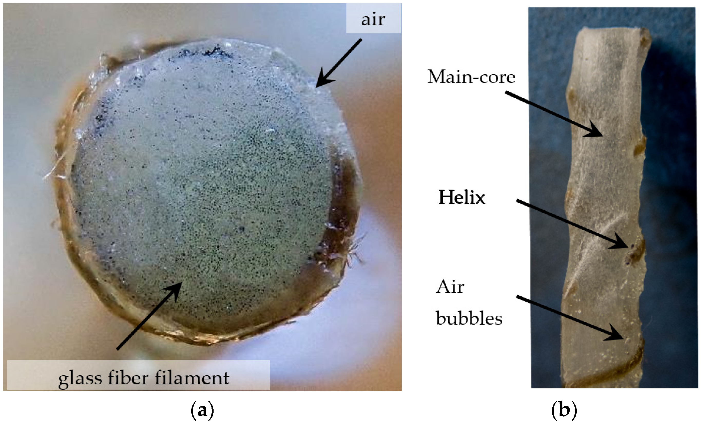
To further evaluate the characteristics of the main core, a transversal and longitudinal cut were made. Both cuts have been sanded up to 2000 Grit to improve their quality, and pictures were taken for closer analysis (see
Figure 10). In these pictures, large air bubbles can be detected on the surface of the main-core. In the center of the main-core, in contrast, the fibers appear to be better embedded in the matrix, with fewer and smaller air inclusions. That indicates an adequate performance of the impregnation unit and the forming die. The air cavities present on the surface can arise from gas escaping the helix when the resin permeates through its fibers. Or might be caused by the main-core fibers coming apart during the winding, causing the trapped air to ascend to the surface.
The mechanical properties of the finally cured reinforcement will be investigated further in the ongoing research. Special focus will be given on the investigation of parameters, which are influencing its mechanical properties. Besides the mechanical properties of the reinforcement itself, pull-out tests are planned to verify the mechanical interlocking capacity of the surface structuring.
5.2. Dynamic Winding Experiments
5.2.1. Experimental Setup
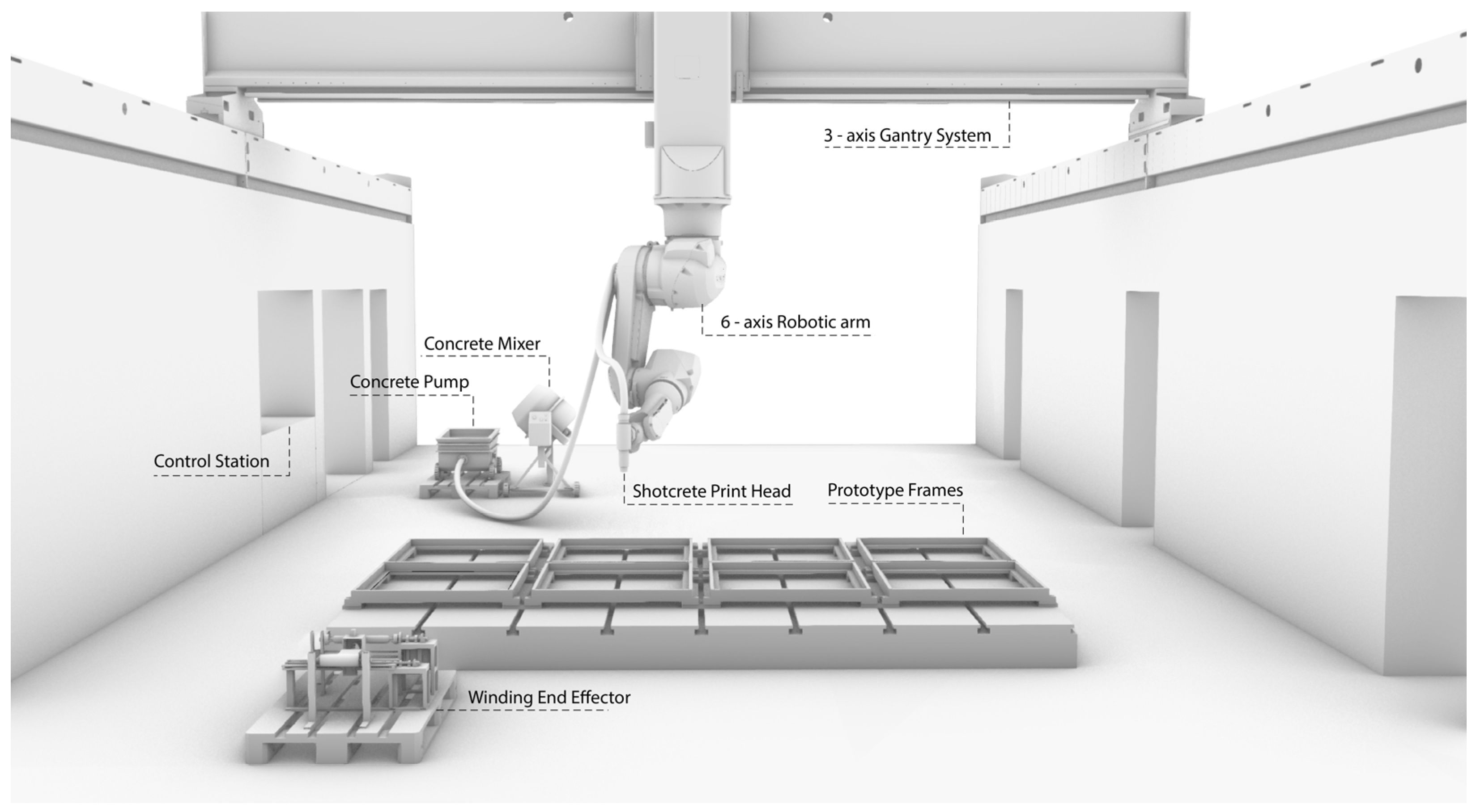
Following the development of a functional prototype for the core winding machine, the end effector was integrated into a 6-axis robot for winding geometrically complex meshes. In accordance with the concept described above, these are then to be coated with shotcrete in a subsequent process. To investigate the basic process behavior, a simple planar and regular mesh geometry were chosen for the first experiments. For the first experiments, eight identical wooden frames with dimensions of 970 mm × 970 mm were set up in the Digital Building Fabrication Laboratory (DBFL) and mounted horizontally on the work tables (see
Figure 11). To facilitate accurate measurement of the frames, the position of the pins around which the fiber is winded was marked with the robot and pins were inserted manually. In addition, a tool head for fiber guiding was 3D printed and mounted on axis 6 of the robot. The core-winding tool was not mounted directly on the robot, but positioned in the immediate proximity of the frames. For the downstream shotcrete tests, the Shotcrete 3D Printing equipment, including concrete mixer and concrete pump, was set up in the workspace of the DBFL. For the shotcrete tests, the winding tool head was removed and replaced by a shotcrete nozzle. The test setup with mounted shotcrete application is shown in
Figure 11; the winding toolhead is depicted in
Figure 12a.
5.2.2. Mesh Configuration
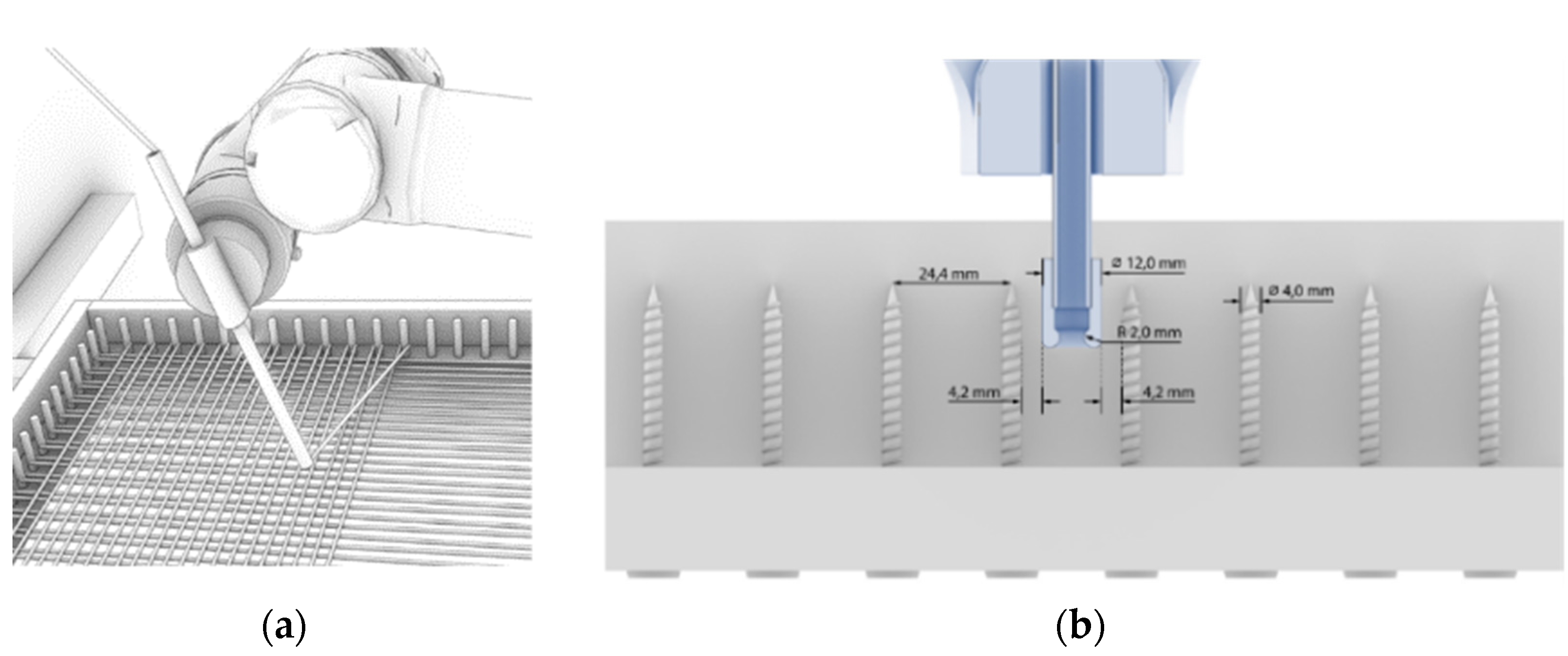
The mesh size is largely determined by the subsequent shotcrete process. The geometry of the mesh must thus be sufficiently wide to allow the concrete to easily penetrate the mesh, but narrow enough to prevent large amounts of concrete from flying through. Another determining factor for the mesh size is that collision-free circumvention of the pins during the winding process is ensured. According to these requirements, a pin spacing of 24.4 mm was chosen, which allows the tool head with a diameter of 12 mm to bypass the 4 mm pins without collision, even in the case of minor path deviations (see
Figure 12b). To simplify the removal of the mesh after winding, the wood screws used as pins were sleeved with a shrink tubing.
5.2.3. Dynamic Winding Results
Based on preliminary studies, a robot winding speed of 41 mm/s was chosen for winding the initial frames. This speed ensured a stall-free operation even with accounting for oscillation effects at maximum distance between the tool head and the core winding machine. With minor technical improvements of the helix winding mechanism on core-winding machine, the winding speed could be more than doubled.
After the process had been tested for collisions in a dry run, epoxy resin was added to the impregnation unit of the core-winding machine. The addition of the resin had two effects in the experiment. First, a lot of excess resin was lost through dripping and secondly the addition of the resin significantly reduced the friction in the system. However, the fiber tension generally allowed a well-defined placement of the filament. Even when surrounding the pins, fibers were kept straight and under tension. An exceptional case arose when the robot moved exactly towards the winding end-effector, and hence no fiber was pulled through the robot movement. As a result, the fiber strand was not continuously tensioned. However, this lack of tension was compensated for by looping around the next pin.
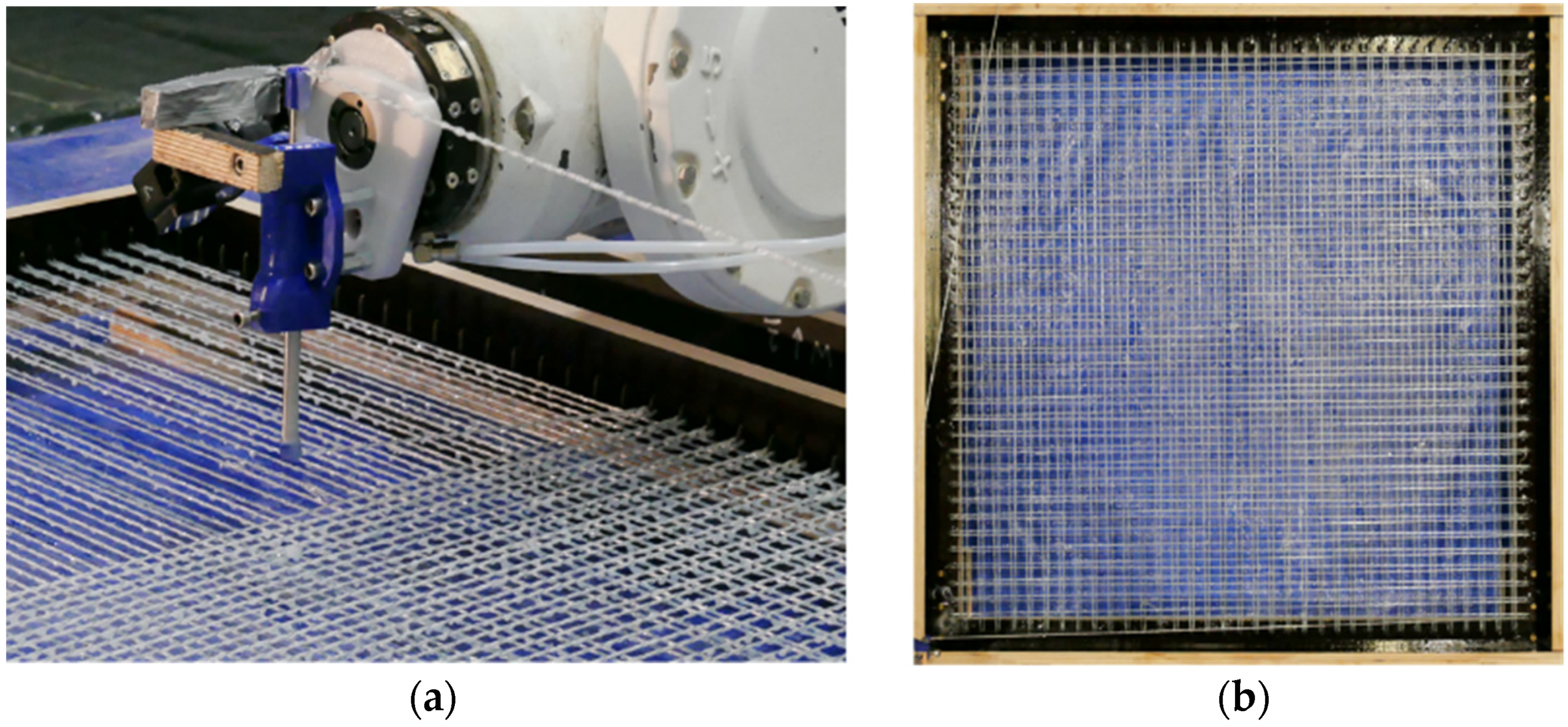
These problems did not emerge when winding the second layer orthogonally, however, precautions needed to be taken in order to not collide with the first layer of fibers. Surrounding the pins was performed at unchanged height, whereas the end effector was lifted when traversing the previously spanned fibers (
Figure 13a). In this manner, collisions could be avoided; however, the resulting mesh exhibits regions with disjointed crossings. Even though it is not investigated yet, if a gapless connection between crossing fibers improves the mechanical properties of fiber reinforced concrete elements, it should be noted that epoxy resin mainly serves for activating all single fibers of a roving. Though for joining crossing fiber strands, it cannot be equated with welded joints like in steel meshes without further investigation.
5.2.4. Evaluation of the Resulting Mesh
In order to assess the accuracy of the final mesh structure, a section of the winded mesh was cut out for optical measurement via a non-distortive two-dimensional 600 dpi scan. By means of computer aided drawing, points were placed wherever the secondary yarn crosses the apparent mid of the roving. The distances between those points were computed automatically and calibrate (see
Figure 14). The uncertainty of this method is conservatively assumed to be below ±1 mm per point, thus resulting in a twofold uncertainty per distance. Two fiber strands in the scanned cut-out exhibit almost double of the desired thread pinch. Those particular deviations may have arisen from an exceeded acceleration limit as mentioned before. When neglecting this data, the overall arithmetic mean lies at 12.13 mm at the peak of a Gaussian-shaped distribution. Based on the assumption of a normal distribution, the standard deviation was calculated to be ±1.37 mm. It is situated in the order of magnitude of the assumed measurement error. Consequently, deviations cannot clearly be traced back to deviations from the process itself. Even if those deviations came exclusively from the dynamic winding, it would still represent a satisfying result. Having a shortening or elongation of the helix of less than 11% for the majority of the wound fibers is not expected to affect the compound-strengthening effect of the helix at all.
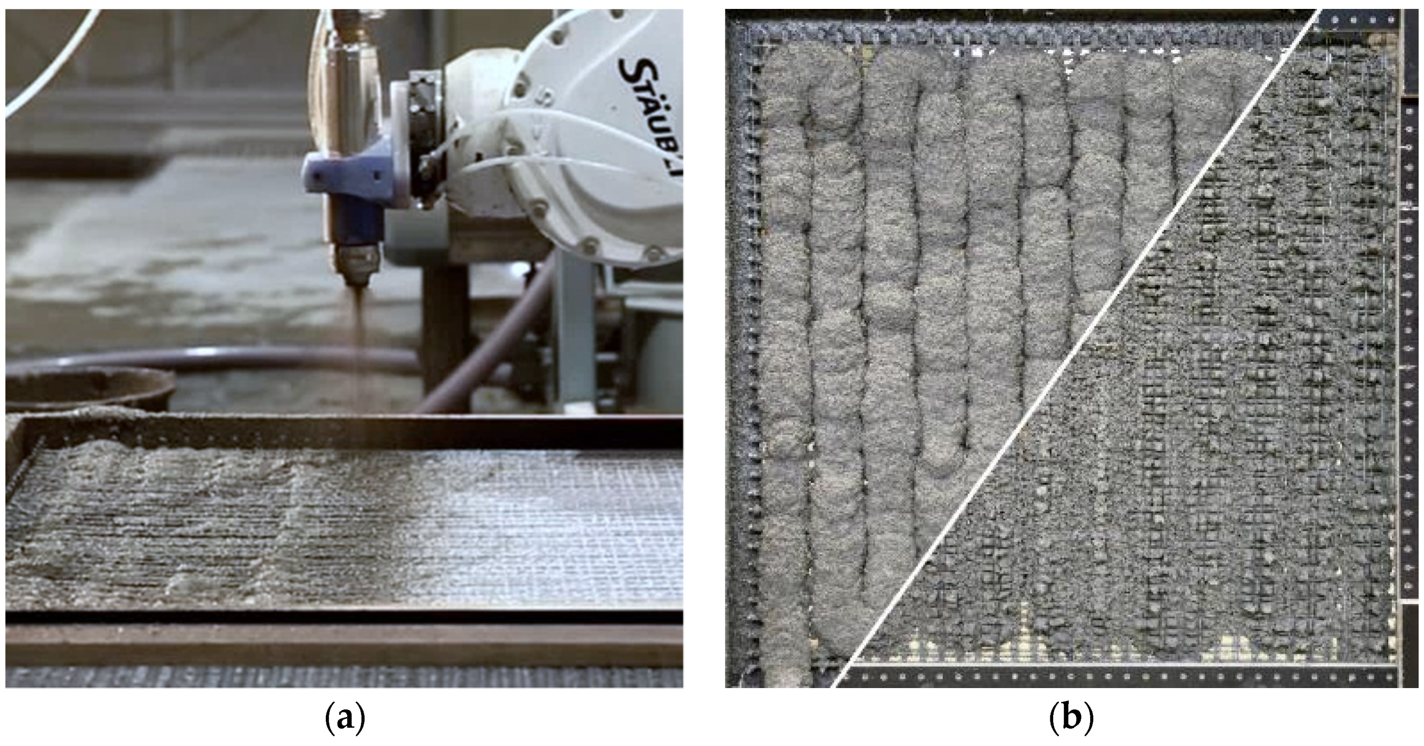
6. Initial Shotcrete Experiments
After 24 h, the meshes were fully cured and the first shotcrete 3D printing process experiments were carried out. In these first trials, the main focus was to determine if the mesh size was chosen appropriately for the shotcrete application, or if it needs to be adjusted for subsequent trials. For this purpose, the meshes were left in their horizontal position. The winding toolhead was dismounted and replaced with the Shotcrete 3D Printing toolhead. A ready-mixed fiber-reinforced fine-grain concrete with a maximum grain size of 2 mm and a compressive strength of 68 MPa was used for spraying [
33]. The material was projected onto the mesh at a distance of 30 cm with an air pressure of 1.5 bar (see
Figure 15a); no shotcrete accelerator was used. The shotcrete easily penetrated through the structure, such that a satisfactory bond would be expected (see
Figure 15b). In order to produce structural elements with high surface quality, the application of shotcrete application from the other side of the mesh, as well as an automated surface finishing, as described in [
34], is planned. The application of concrete took 4 min. Due to the horizontal position and the self-weight of the concrete, a slight deflection of 2.5 cm occurred.
7. Discussion and Future Work
The results presented in this article demonstrate a conceptual and technical development that has been verified by initial experiments. On the technical side, there are several improvements that will enable the fabrication of more complex mesh geometries and the verification of their structural integrity. Regarding the mesh fabrication, the following challenges need to be addressed in future work: First, the speed of the winding process needs to be increased. This predominantly requires the replacement of some components of the core winding machine, in particular, the motor responsible for winding the helix around the core. Second, the impregnation of the core-winded fiber should be improved so that there is no loss and contamination of the equipment.
In addition to the above-mentioned technical investigations, there are further investigations to be carried out on a conceptual level. This concerns both the production of the meshes and the additive application of the shotcrete itself. With regard to the former, for example, different winding concepts are possible. Among others, these include the fabrication of multi-layered meshes wound around a prefabricated frame (as opposed to the single layer mesh presented in this paper), but also the prefabrication of individualized reinforcement segments that are assembled into a more complex mesh geometry (see
Figure 16a). Moreover, winding around a pre-printed core is also considered as a strategy (see
Figure 16b). With regard to the AM strategy, fiber winding is also to be investigated for other AM technologies, for example concrete extrusion and particle bed printing.
8. Conclusions
Both their physical properties and the advances in automated manufacturing make FRP materials a serious alternative to steel reinforcement in additive manufacturing with concrete. More specifically, FRP reinforcement provides high design flexibility, increased resistance to corrosion, lighter weight, and reduces cement consumption by minimizing the required concrete cover. A promising manufacturing technique for these materials is robotic fiber winding, especially in combination with additive manufacturing methods like Shotcrete 3D Printing. By implementing this process to concrete reinforcement manufacturing, it opens new ways to think and realize concrete structures.
A key advantage over typical FRP rods and FRP textiles is the ability to create geometrically complex, large-area elements fully automatically, without having to assemble or patch them. Additionally, by combining the surface treatment of FRP rebars to this process, the bond strength of the reinforcement can be significantly increased. This research aimed to prototype a tool to combine core winding technics and robotic winding deposition to achieve that goal. The dynamic winding end-effector realized provides the ability to continuously and dynamically fabricate a 3D winded filament similarly to commonly pultruded rebars. However, the use of resin with higher processing time and the ability to cure at room temperature allows the use of this technique in combination with robotic winding.
Consequently, this paper is completed with an exemplary application of the dynamic winding end-effector. A square-shaped dense mesh was winded in order to generate a structure that serves as reinforcement and a form-defining element for the Shotcrete 3D Printing process. Using an experimental set up for additively concreting the mesh was also successfully tested, but will be addressed in follow-up publications exploring specific parameters such as geometric freedom; concrete adhesion to the mesh; excess of material; and distance, angle, and speed of the spraying process.
Author Contributions
Conceptualization of robotically fabricated reinforcement approach, N.H. and C.H.; conceptualization of the core winding process and machine, C.H. with M.B. and W.L.; methodology, N.H. and C.H. with M.B.; software for core winding machine, M.B. and W.L.; software for robotic frame winding and Shotcrete 3D Printing, S.G., N.K.; validation or the core winding process, M.B., W.L., validation of the robotic frame winding and Shotcrete 3D Printing process, S.G., N.K.; formal analysis, M.B., W.L., S.G., N.K.; investigation, M.B., W.L., S.G., N.K.; resources, N.H. and C.H.; data curation, N.H., C.H. with M.B.; writing, N.H., W.L., M.B., S.G., N.K. and T.R.; review and editing, N.H., C.H., M.B., S.G., N.K. and T.R.; visualization, N.K., S.G., W.L.; supervision, N.H., C.H., M.B.; project administration, N.H., C.H., M.B.; funding acquisition, N.H., C.H.; All authors have read and agreed to the published version of the manuscript.
Funding
The authors would like to thank the German Research Foundation (DFG), for funding the Collaborative research center TRR 277 Additive Manufacturing in Construction and the DFG Large Research Equipment, Digital Building Fabrication Laboratory (project numbers 416601133 and 414265976), as well as the Ministry of Science and Culture of Lower Saxony (MWK). The Junior Professorship in Digital Building Fabrication is generously funded by the Gerhard und Karin Matthäi Foundation. Furthermore, we acknowledge support by the German Research Foundation and the Open Access Publication Funds of Technische Universität Braunschweig.
Conflicts of Interest
The authors declare no conflict of interest. The funders had no role in the design of the study; in the collection, analyses, or interpretation of data; in the writing of the manuscript, or in the decision to publish the results.
References
- Mechtcherine, V.; Buswell, R.; Kloft, H.; Bos, F.P.; Hack, N.; Wolfs, R.; Saranjan, J.; Nematollahi, B.; Ivaniuk, E.; Neef, T. Integrating Reinforcement In Digital Fabrication With Concrete: A Review And Classification Framework. Cem. Concr. Compos. 2021, 103964. [Google Scholar] [CrossRef]
- Kloft, H.; Empelmann, M.; Hack, N.; Herrmann, E.; Lowke, D. Reinforcement Strategies For 3D-concrete-printing. Civ. Eng. Des. 2020, 2, 131–139. [Google Scholar] [CrossRef]
- Morgan, R. Saint Budoc And Lambot’s Washerwomen. In Ferrocement: Proceedings of the Fifth International Symposium on Ferrocement; Nedwell, P.J., Ed.; E & F.N. Spon: London, UK, 1994; pp. 27–34. ISBN 0-419-19700-1. [Google Scholar]
- Gargiani, R. The Rhetoric of Pier Luigi Nervi: Concrete and Ferrocement Forms; EPFL Press: Lausanne, Switzerland, 2016; ISBN 978-2-940222-95-7. [Google Scholar]
- Greco, C. Pier Luigi Nervi: Von den Ersten Patenten bis zur Ausstellungshalle in Turin 1917–1948; Quart-Verlag: Luzern, Switzerland, 2008; ISBN 978-3-907631-45-4. [Google Scholar]
- Hart, H.; Amir, F. Investigating A Structural Form System For Concrete Girders Using Commercially Available GFRP Sheet-Pile Sections. J. Compos. Constr. 2009, 13, 455–465. [Google Scholar]
- Son, J.K.; Fam, A. Finite Element Modeling Of Hollow And Concrete-Filled Fiber Composite Tubes In Flexure: Model Development, Verification And Investigation Of Tube Parameters. Eng. Struct. 2008, 30, 2656–2666. [Google Scholar] [CrossRef]
- Hack, N.P. Mesh Mould: A Robotically Fabricated Structural Stay-in-Place Formwork System. Ph.D Thesis, ETH Zurich, Zurich, Switzerland, 2018. [Google Scholar] [CrossRef]
- Hack, N.; Lauer, W.V.; Gramazio, F.; Kohler, M.; Blank, N. Method of Fabricating a 3-Dimensional Structure, Mesh Formwork Element for Fabricating a 3-Dimensional Structure, and Method of Fabricating the Same, WO/2015/034438. 2013. Available online: https://www.google.ch/patents/WO2015034438A1?cl=en (accessed on 23 February 2020).
- Hack, N.; Dörfler, K.; Walzer, A.N.; Wangler, T.; Mata-Falcón, J.; Kumar, N.; Buchli, J.; Kaufmann, W.; Flatt, R.J.; Gramazio, F.; et al. Structural Stay-In-Place Formwork For Robotic In Situ Fabrication Of Non-Standard Concrete Structures: A Real Scale Architectural Demonstrator. Autom. Constr. 2020, 115, 103197. [Google Scholar] [CrossRef]
- Graser, K.; Baur, M.; Apolinarska, A.A.; Dörfler, K.; Hack, N.; Jipa, A.; Sandy, T.; Lloret-Fritschi, E.; Pont, D.S.; Hall, D.M.; et al. DFAB HOUSE—A Comprehensive Demonstrator of Digital Fabrication in Architecture. In Fabricate 2020: Making Resilient Architecture; Burry, J., Sabin, J.E., Sheil, B., Skavara, M., Eds.; UCL Press: London, UK, 2020; pp. 130–139. [Google Scholar]
- Dörfler, K.; Hack, N.; Sandy, T.; Giftthaler, M.; Lussi, M.; Walzer, A.N.; Buchli, J.; Gramazio, F.; Kohler, M. Mobile Robotic Fabrication Beyond Factory Conditions: Case Study Mesh Mould Wall of the DFAB HOUSE. Constr. Robot. 2019. [Google Scholar] [CrossRef] [Green Version]
- Kloft, H.; Gehlen, C.; Dörfler, K.; Hack, N.; Henke, K.; Lowke, D.; Mainka, J.; Raatz, A. TRR 277: Additive Fertigung Im Bauwesen. Bautechnik 2021. [Google Scholar] [CrossRef]
- Doerstelmann, M.; Knippers, J.; Koslowski, V.; Menges, A.; Prado, M.; Schieber, G.; Vasey, L. ICD/ITKE Research Pavilion 2014–15: Fibre Placement On A Pneumatic Body Based On A Water Spider Web. Archit. Des. 2015, 85, 60–65. [Google Scholar] [CrossRef]
- Doerstelmann, M.; Knippers, J.; Menges, A.; Parascho, S.; Prado, M.; Schwinn, T. ICD/ITKE Research Pavilion 2013–14: Modular Coreless Filament Winding Based On Beetle Elytra. Archit. Des. 2015, 85, 54–59. [Google Scholar] [CrossRef]
- Solly, J.; Frueh, N.; Saffarian, S.; Prado, M. ICD/ITKE Research Pavilion 2016/2017: Integrative Design Of A Composite Lattice Cantileve. In Proceedings of the IASS Symposium 2018 Creativity in Structural Design, Boston, MA, USA, 16–20 July 2018; pp. 2–8. [Google Scholar]
- Schinegger, K.; Rutzinger, S.; Ladinig, J.; Li, M. Becoming Structure BT-Impact: Design With All Senses; Gengnagel, C., Baverel, O., Burry, J., Thomsen, M.R., Weinzierl, S., Eds.; Springer International Publishing: Cham, Switzerland, 2020; pp. 214–223. ISBN 978-3-030-29829-6. [Google Scholar]
- C.C.C. e. V. C3: Carbon Concrete Composites. 2017. Available online: https://www.bauen-neu-denken.de/en/#about-c3 (accessed on 7 June 2021).
- Scheerer, S.; Schladitz, F.; Curbach, M. Textile Reinforced Concrete—From The Idea To A High Performance Material. In Proceedings of the 11th International Symposium on Ferrocement and Textile Reinforced Concrete 3rd ICTRC, Aachen, Germany, 7–10 June 2015; pp. 15–34. [Google Scholar]
- Mechtcherine, V.; Schneider, K.; Brameshuber, W. Mineral-Based Matrices For Textile-Reinforced Concrete. In Textile Fibre Composites in Civil Engineering; Woodhead Publishing: Cambridge, UK, 2016. [Google Scholar]
- Popescu, M. KnitCrete: Stay-in-Place Knitted Fabric Formwork for Complex Concrete Structures; ETH Zurich—Department of Architecture: Zurich, Switzerland, 2019. [Google Scholar]
- Ayres, P.; da Silva, W.R.L.; Nicholas, P.; Andersen, T.J.; Greisen, J.P.R. SCRIM—Sparse Concrete Reinforcement In Meshworks BT-Robotic Fabrication In Architecture, Art And Design 2018; Willmann, J., Block, P., Hutter, M., Byrne, K., Schork, T., Eds.; Springer International Publishing: Cham, Switzerland, 2019; pp. 207–220. ISBN 978-3-319-92294-2. [Google Scholar]
- Taha, N.; Walzer, A.N.; Ruangjun, J.; Lloret-fritschi, E.; Gramazio, F.; Kohler, M. Robotic AeroCrete A Novel Robotic Spraying And Surface Treatment Technology For The Production of Slender Reinforced Concrete Elements. In Proceedings of Architecture in the Age of the 4 Th Industrial Revolution, Porto, Portugal, 11–13 September 2019; pp. 245–254. [Google Scholar]
- Lindemann, H.; Gerbers, R.; Ibrahim, S.; Dietrich, F.; Herrmann, E.; Dröder, K.; Raatz, A.; Kloft, H. Development Of A Shotcrete 3D-Printing (SC3DP) Technology For Additive Manufacturing Of Reinforced Freeform Concrete Structures BT. In First RILEM International Conference On Concrete And Digital Fabrication—Digital Concrete 2018; Wangler, T., Flatt, R.J., Eds.; Springer International Publishing: Cham, Switzerland, 2019; pp. 287–298. ISBN 978-3-319-99519-9. [Google Scholar]
- Kloft, H.; Hack, N.; Mainka, J.; Brohmann, L.; Herrmann, E.; Ledderose, L.; Lowke, D. Additive Fertigung Im Bauwesen: Erste 3-D-gedruckte Und Bewehrte Betonbauteile Im Shotcrete-3-D-Printing-Verfahren (SC3DP). Bautechnik 2019, 96, 929–938. [Google Scholar] [CrossRef]
- Aiello, M.A.; Leone, M.; Pecce, M. Bond Performances Of FRP Rebars-Reinforced Concrete. J. Mater. Civ. Eng. 2007, 19, 205–213. [Google Scholar] [CrossRef]
- Portal, N.W. Sustainability and Flexural Behaviour of Textile Reinforced Concrete; Chalmers University of Technology: Göteborg, Sweden, 2013; ISBN 9789173855525. [Google Scholar]
- Böhm, R.; Thieme, M.; Wohlfahrt, D.; Wolz, D.S.; Richter, B.; Jäger, H.; Sebastian, D.; Id, W.; Richter, B.; Jäger, H. Reinforcement Systems For Carbon Concrete Composites Based On Low-Cost Carbon Fibers. Fibers 2018, 6, 56. [Google Scholar] [CrossRef] [Green Version]
- Portnov, G.; Bakis, C.E.; Lackey, E.; Kulakov, V. FRP Reinforcing Bars—Designs And Methods of Manufacture (Review of Patents). Mech. Compos. Mater. 2013, 49, 381–400. [Google Scholar] [CrossRef]
- Esfandeh, M.; Sabet, A.R.; Rezadoust, A.M.; Alavi, M.B. Bond Performance Of FRP Rebars With Various Surface Deformations In Reinforced Concrete. Polym. Compos. 2009, 30, 576–582. [Google Scholar] [CrossRef]
- Besserud, K.; Katz, N.; Beghini, A. Structural Emergence: Architectural And Structural Design Collaboration At SOM. Archit. Des. 2013, 83, 48–55. [Google Scholar] [CrossRef]
- Üstün, T.; Ulus, H.; Karabulut, S.E.; Eskizeybek, V.; Şahin, Ö.S.; Avci, A.; Demir, O. Evaluating The Effectiveness Of Nanofillers In Filament Wound Carbon/Epoxy Multiscale Composite Pipes. Compos. Part B Eng. 2016, 96, 1–6. [Google Scholar] [CrossRef]
- Bauchemie, M.C. Nafufill KM 250. 2021. Available online: https://www.mc-bauchemie.com/products/concrete-repair/concrete-replacement/nafufill-km-250.html (accessed on 21 April 2021).
- Hack, N.; Kloft, H. Shotcrete 3D Printing Technology For The Fabrication Of Slender Fully Reinforced Freeform Concrete Elements With High Surface Quality: A Real-Scale Demonstrator. In 2nd RILEM International Conference on Concrete and Digital Fabrication; Salet, T.A.M., Bos, F.P., Wolfs, R., Eds.; Rilem Publications: Eindhoven, The Netherlands, 2020. [Google Scholar]
Figure 1.
Classification approach for reinforcement in Additive Manufacturing with concrete.
Figure 1.
Classification approach for reinforcement in Additive Manufacturing with concrete.
Figure 2.
(a) Robotic in situ fabrication of an individualized stay-in-place formwork; (b) manual concrete filling process; (c) finished loadbearing wall.
Figure 2.
(a) Robotic in situ fabrication of an individualized stay-in-place formwork; (b) manual concrete filling process; (c) finished loadbearing wall.
Figure 3.
Integration of prefabricated carbon fiber mats as reinforcement for additive manufacturing with concrete: (a) concrete extruded onto a standard reinforcement mat; (b) glass fiber reinforced concrete sprayed onto a standard reinforcement mat; (c) a reinforcement mat pressed into fresh concrete and subsequently covered through spraying and automated smoothing.
Figure 4.
Overall fabrication concept: (a) A robot winds a reinforcement mesh around an individualized frame; (b) concrete is applied to the mesh using the Shotcrete 3D Printing process.
Figure 4.
Overall fabrication concept: (a) A robot winds a reinforcement mesh around an individualized frame; (b) concrete is applied to the mesh using the Shotcrete 3D Printing process.
Figure 5.
Carbon fiber reinforcing bars with different ribbing for better mechanical bonds in concrete. From left to right: plain bar without surface functionalization, core-winded using tape, contour milled, form-pressed, twisted, and pinned elements [
28].
Figure 5.
Carbon fiber reinforcing bars with different ribbing for better mechanical bonds in concrete. From left to right: plain bar without surface functionalization, core-winded using tape, contour milled, form-pressed, twisted, and pinned elements [
28].
Figure 6.
Dynamic winding machine: (a) Schematic representation of the machine: (1) main-core feeding unit; (2) main-core movement sensing unit; (3) impregnation unit; (4) helix winding unit; (5) tensioning unit; (6) robot end effector; (b) 3D schematic of the helix winding unit: (7) secondary bobbin on which the helix fibers are winded; and (8) the final prepared filament.
Figure 7.
Prototype of a dynamic winding machine.
Figure 7.
Prototype of a dynamic winding machine.
Figure 8.
Calculation of the relation between the secondary yarn length and the total wire length.
Figure 8.
Calculation of the relation between the secondary yarn length and the total wire length.
Figure 9.
Winding specimens: (a) with dry fibers and (b) with resin impregnated fibers.
Figure 9.
Winding specimens: (a) with dry fibers and (b) with resin impregnated fibers.
Figure 10.
Photo of a transversal (a) and longitudinal (b) cut of the main core.
Figure 10.
Photo of a transversal (a) and longitudinal (b) cut of the main core.
Figure 11.
Fiber winding and 3D shotcrete fabrication setup at the DBFL, ITE.
Figure 11.
Fiber winding and 3D shotcrete fabrication setup at the DBFL, ITE.
Figure 12.
Simulation of robotically winding a dense reinforcement mesh (a), detailed proportions of pins and guiding tool; (b) dimensions of the tooling setup.
Figure 12.
Simulation of robotically winding a dense reinforcement mesh (a), detailed proportions of pins and guiding tool; (b) dimensions of the tooling setup.
Figure 13.
Dynamic mesh winding process: (a) robot guiding the core-winded fibers over a frame, generating a dense reinforcement mesh; (b) finished mesh before concrete application.
Figure 13.
Dynamic mesh winding process: (a) robot guiding the core-winded fibers over a frame, generating a dense reinforcement mesh; (b) finished mesh before concrete application.
Figure 14.
Assessment of the secondary yarn’s thread pitch regularity: (a) excerpt from the computer-aided measurement method; (b) histogram based on 598 valid distances.
Figure 14.
Assessment of the secondary yarn’s thread pitch regularity: (a) excerpt from the computer-aided measurement method; (b) histogram based on 598 valid distances.
Figure 15.
Automated application of shotcrete (a) robotic shotcreting process; (b) first results of robotically shotcreting a winded reinforcement mesh (front and rear).
Figure 15.
Automated application of shotcrete (a) robotic shotcreting process; (b) first results of robotically shotcreting a winded reinforcement mesh (front and rear).
Figure 16.
Advanced concepts for the integration of prefabricated fiber reinforcement in the additive manufacturing process with concrete: (a) pre-winded assembled fibers; (b) reinforced printed core.
Figure 16.
Advanced concepts for the integration of prefabricated fiber reinforcement in the additive manufacturing process with concrete: (a) pre-winded assembled fibers; (b) reinforced printed core.
Table 1.
Concept of dynamic fiber winding machine with helix winding unit.
Table 1.
Concept of dynamic fiber winding machine with helix winding unit.
| Principal Element | Tasks | Technical Solutions |
|---|
| Main-core feeding unit | Stores and dispense the main-core fibers
Tension the main-core | Wind the main-core roving on a spool
Adjustable friction brake |
| Main-core movement sensing unit | Sense the displacement of the main-core
Measure the displacement of the main-core
Analyze and transmit the information | Tension the main-core on a roller Rotary encoder
Arduino Uno |
| Impregnation unit | Ensure the flexibility of the main core
Cure without the need of an oven
Saturate the main-core with the resin
Increase the impregnation efficiency
Shape the main-core | Use a resin with a long working time
Use a resin able to cure at room temperature
Dip-type impregnation system
Tensioning system
Conical Die |
| Helix Winding unit | Store and dispense the secondary fiber
Tension the secondary fiber
Deposit the secondary fiber on the main-core
Rotate the winding wheel according to the sensors data | Wind the fiber on a spool
Adjustable friction brake
Fix the secondary fiber-spool on a wheel rotating around the main-core
Stepper Motor |
| Tensioning unit | Keep the finally prepared fiber tensioned while winding | Block and tackle with pulleys
Mass to add a constant weight force |
| Publisher’s Note: MDPI stays neutral with regard to jurisdictional claims in published maps and institutional affiliations. |
© 2021 by the authors. Licensee MDPI, Basel, Switzerland. This article is an open access article distributed under the terms and conditions of the Creative Commons Attribution (CC BY) license (https://creativecommons.org/licenses/by/4.0/).


 ,
, 


