1. Introduction
Since the middle of last century, traditional materials like steel or aluminum alloys have been partially replaced by composite materials (i.e., fiber reinforced polymers) in several industrial sectors, such as nautical, aeronautical and aerospace, mainly thanks to their low weight, high static and dynamic mechanical performances and good chemo-physical properties.
It is worth noting that, regardless of the engineering field, monolithic structures are extremely unusual or limited to very particular applications; i.e., composite components are frequently joined to other composite or metallic substrates through structural adhesives [
1,
2] or mechanical inserts, such as bolts, rivets and so on [
3,
4].
Structural adhesives, on the one hand, are recommended because the absence of holes avoids the occurrence of delamination phenomena within composite substrates. Furthermore, the absence of inserts allows one to reduce the weight of a structure and prevents degradation phenomena caused by galvanic corrosion; however, this option does not facilitate structural disassembly (i.e., in case of maintenance and repair operations). Vice versa: mechanical joints are easy to disassemble and able to sustain higher loads in comparison to their adhesive counterparts.
Due to the common use of mechanical connections to join composite or hybrid structures, the bearing performances of pin-loaded composite laminates have been widely analyzed in the last few years by several authors [
5,
6,
7,
8].
In this context, the kind of failure mechanism (i.e., bearing, net-tension, shear out and cleavage), and consequently, the capability of pinned laminates to support a load was investigated as a function of their geometrical parameters [
9,
10,
11,
12,
13]. In particular, in our recent paper [
14], pinned, glass-reinforced laminates were tested with varying hole diameter D, laminate width W and hole center distance from the free edge of laminate, E; thus, highlighting that the pin-loaded composite configuration has a relevant influence on the mechanical stability and on the joint-failure mechanism.
As already stated, several papers have been focused on the bearing behavior of fiber-reinforced, polymer-based materials. Nevertheless, a further relevant aspect which has attracted increasing attention in the last few years is the evaluation of joints’ durability; i.e., the knowledge of how the bearing performance can be modified when composite joints are exposed to aggressive environments, such as marine ones [
15,
16,
17,
18,
19,
20].
In particular, Ozen and Sayman [
15] studied, both experimentally and numerically, the bearing strength behavior of pinned, glass-fiber reinforced epoxy composites with two serial holes. In order to evaluate the effects of preload torques and seawater immersion on the joints bearing strength, unaged and seawater immersed (for 24 h) specimens were tested at varying preload moments for their un-immersed condition. It was observed that the seawater immersion caused a failure load decrease in the specimens without a preload moment and no noticeable variation in those preloaded.
The effect of seawater on failure behavior of mechanically-fastened, glass-fiber reinforced composites with stacking sequence [0/90/45/−60]
s was analyzed by Sayman et al. [
16]. The experimental results evidenced that the immersion into seawater for 200 days of the composite specimens can cause a noticeable decrease in their failure loads. Karakuzu et al. [
18] immersed pinned, glass-fiber reinforced laminates in the water of the Aegean Sea for a maximum interval time of 12 months, evidencing that the detrimental effect of the sea water immersion is affected by the geometrical parameters. In particular, they manufactured and tested specimens with edge distance to pin diameter ratios (
E/
Ds) in the range 1–5 and with width to pin diameter ratios (
W/
Ds) equal to 3 and 4, resultantly, showing that the bearing strength maximum reduction due to the seawater effect was achieved for
E/
D = 3 and
W/
D = 3.
Esendemir and Cabioglu [
20] compared the effects of various types of environments on the bearing strength and failure modes of woven glass epoxy pinned composites. In particular, they exposed specimens (at varying edge distance to hole diameter and specimen width to hole diameter ratios) to a cold environment (i.e., −18 °C), hot environment (i.e., 30 °C), room temperature (i.e., 21 °C), humid environment (i.e., 70% RH) and seawater environment for a period of 2 months. The experimental results showed that different environmental conditions do not modify the failure modes (net tension, shear-out, bearing and mixed) for a specific geometrical configuration. Moreover, it was evidenced that the bearing strength of composite-pinned joints is affected at different levels as a function of the environmental conditions.
The widespread use of composite laminates for nautical applications makes this issue extremely interesting for the designers, in order to understand how the exposure time can modify the predominant failure mechanism, and consequently, the structural performance of the joint.
In the present paper, the same pinned, glass-fiber reinforced laminates studied in our previous work [
14] were exposed to salt-spraying, foggy conditions (up to 60 days) to evaluate the induced change on the failure mechanisms and the consequent reduction of the joint mechanical performances. Furthermore, the evaluation of the experimental and theoretical failure maps at varying joint geometry was also investigated, also evidencing how the critical values of
E/
D and
W/
D ratios can be altered in a marine environment.
3. Results and Discussion
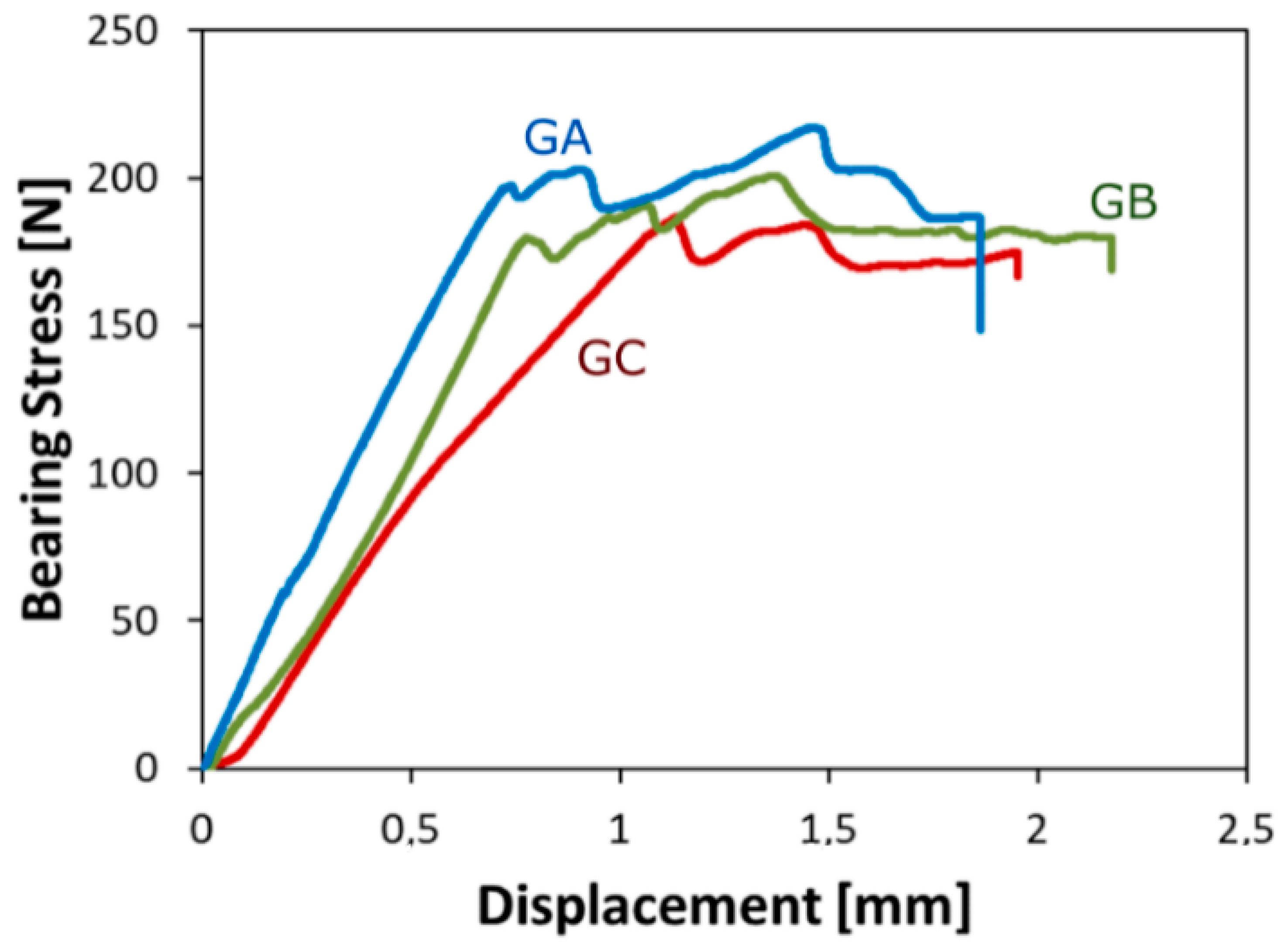
Figure 1 shows the stress versus displacement curves at increasing aging time for pin loaded glass laminates characterized by diameter,
D = 4 mm; width,
W = 15 mm; and edge distance,
E = 12 mm (i.e., geometrical ratios
W/
D = 3.75 and
E/
D = 3.0). Initially, all curves show a linear relationship between stress and displacement. The slope of this trend could be related to the joint stiffness. Afterwards, at increasing displacement, depending on aging time, a gradual deviation from linearity occurs. Finally, all specimens tend to reach a plateau zone at a quite constant stress, beyond which the specimen fails. All the specimens showed a bearing failure mechanism.
Due to the applied aging conditions, a slight modification in the stress vs. displacement trend can be evidenced. The unaged glass laminate (sample GA) has good mechanical stability, as identifiable by the acceptable stiffness and strength of the pinned joint. The high stiffness can be argued by the quite stable linear trend in the first part of the curve and by the higher slope in the stress-displacement curve compared to the other batches. Afterward, at about 190–200 MPa, a stress stabilization was reached. A progressive fluctuation in stress at increasing displacement is observed up to reach a maximum stress over 200 MPa, beyond which the failure of the sample occurred. This behavior can be related to the compression collapse of the epoxy matrix just behind the pin/hole contact area.
Instead, analyzing the curve trend on glass laminates aged for increasing exposure time in a salt/fog environment, an evident reduction of their mechanical performances can be shown. A slight reduction of the maximum stress gradually occurs at increasing aging time (about 7% and 14% lower compared to the unaged sample (batch GA) for batches GB and GC, respectively). At the same time, a significant reduction of the linear slope of the curve can be highlighted. This deviation is more sensitive for GC sample where a gradual deviation from linearity can be observed at low stress level. E.g., a stress threshold of about 100 MPa can be identified for GC sample, after which a deviation from the linear trend becomes sensitive. It is widely known that glass-fiber reinforced composites gradually absorb water under salt/fog exposure. This favors softening phenomena of the matrix; thus, leading to the decrease of composites mechanical properties [
21,
22]. In addition, the loss of fiber-matrix adhesion due to the physical and chemical effects of water molecules on both fibers and the fiber-matrix interface contributes a lot to the deterioration; i.e., the limited capability of the interface area to transfer the stresses implies an irreversible reduction of both strength and stiffness of the aged composites.
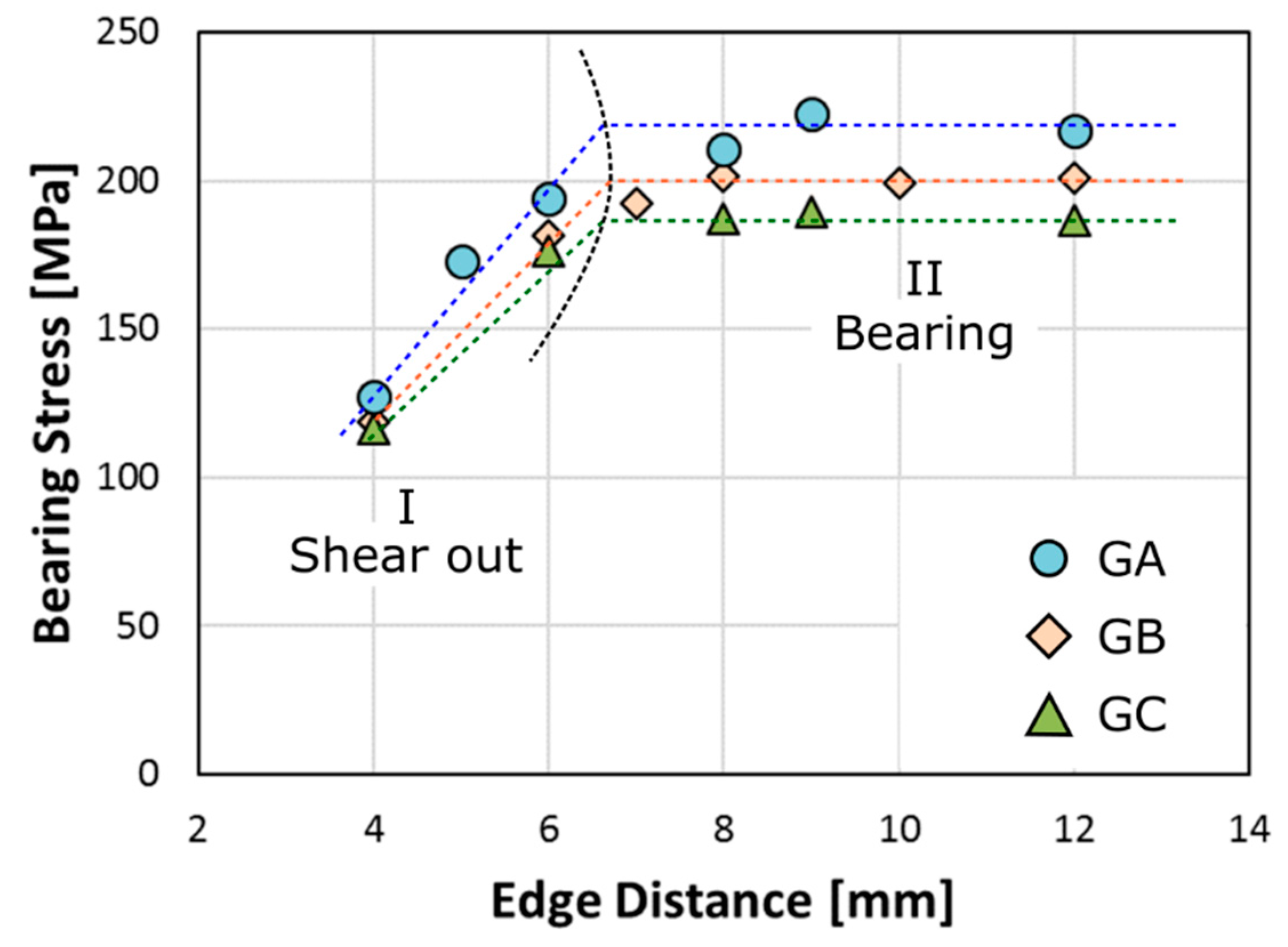
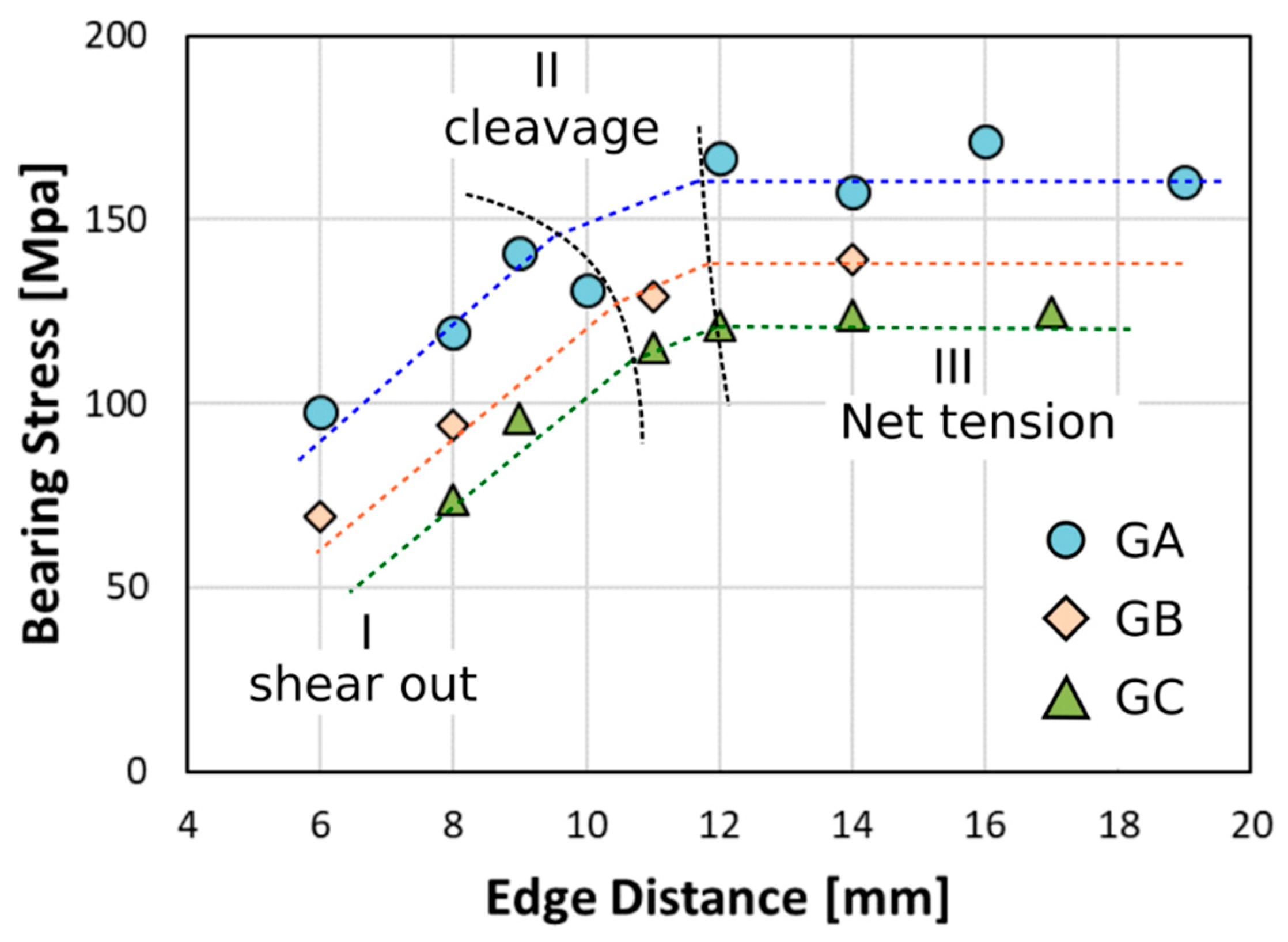
Further information can be acquired by evaluating the maximum bearing stress evolution at increasing edge distance, E, for pin loaded laminates with hole diameter
D = 4 mm and width
W = 15 mm (
W/
D = 3.750) for all batches (
Figure 2). A gradual increase of the maximum bearing stress (
σb) occurs with an increasing
E/
D ratio until a critical threshold value can be observed, accordingly to previous results [
23,
24].
In the experimental evolution of the curves, a bilinear trend has been identified. Each segment can be attributed to a specific and distinct fracture mechanism. In particular, the triggering of damage phenomena related to shear out fracture mechanisms are favored at low edge distance (region I). This phenomenon occurs considering the high stress level generated in the region just behind the pin contact area. This area is very restricted (edge distance,
E, is in the range 4–6 mm), stimulating localized stress that activate a catastrophic shear fracture at very low stress values. This fracture mechanism is strongly dependent on the distance of the hole center from the laminate edge. This is confirmed by the high slope of the linear trend in this region, for which it is clear that there is a significant increase in bearing stress due to a slight increase of distance
E (
σb increase about of 50%, for all batches due to an increase of
E distance form 4 toward 6 mm). A slight reduction of the slope of the shear out trend can be identified at increasing aging time. Although the reduced diameter of the pin (4 mm) significantly exalts the stress concentration in the pin/hole contact area stimulating the bearing failure mechanism [
12].
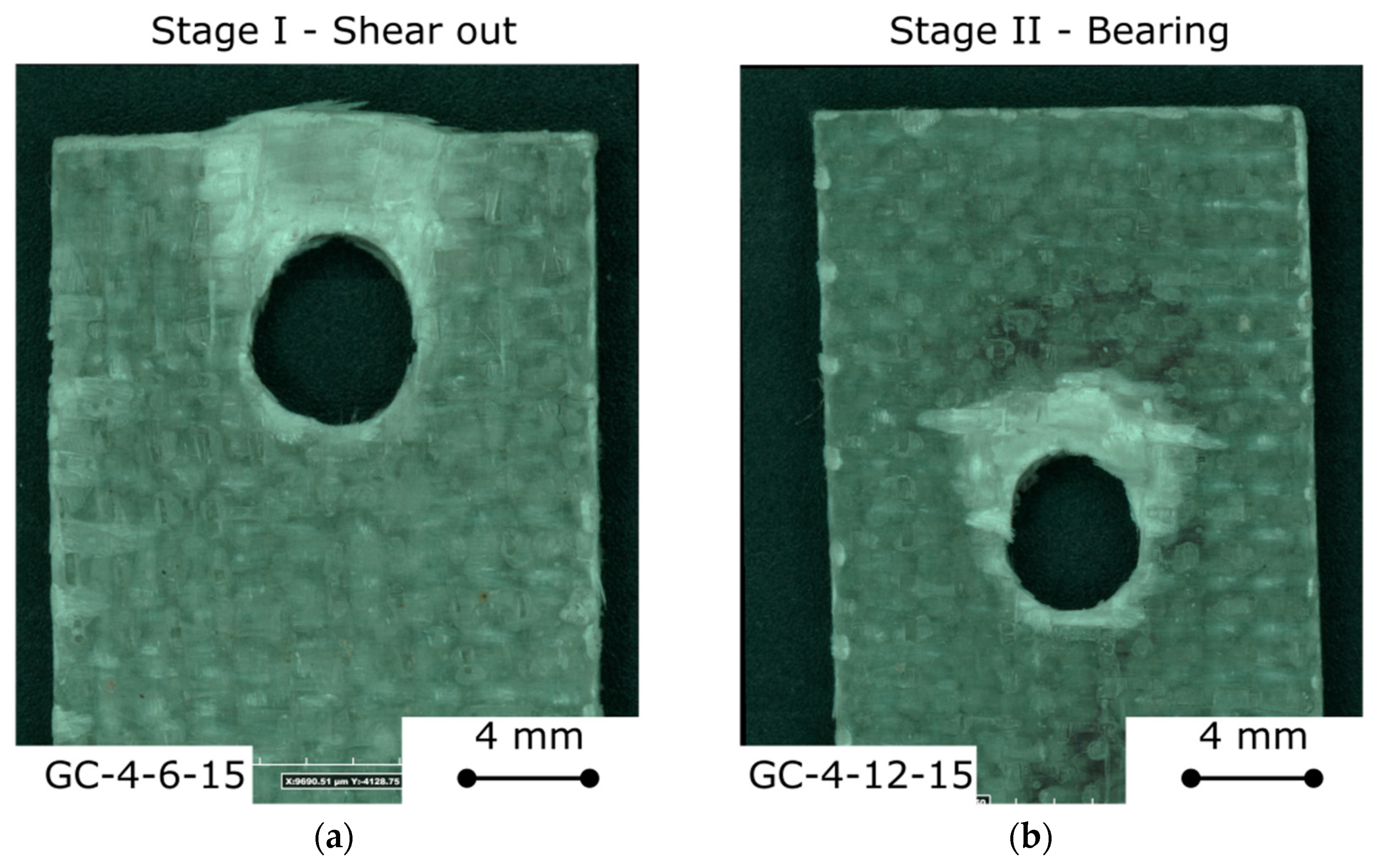
The fracture image of GC-4-6-15 sample, used as reference sample of stage II damaging for shear out, is reported in
Figure 3a. In the upper section of the joint toward the free its edge a shear crack longitudinally propagated along the applied load direction are clearly identified. This premature damage mechanism was triggered due to the proximity of the hole from the sample free edge that significantly reduced the shear out resistance limit for this type of joint geometry.
Afterward, for edge distance higher than 6–8 mm (i.e.,
E/
D > 1.5–2.0) the bearing stress reaches a plateau (region II). In this region, the prevailing failure mechanism is bearing mode [
10] and, for this reason, the stress value reached is indicated as bearing stress at failure. As can be seen from the horizontal trend of the curve of the region II, the bearing stress is also independent by
E and remains almost constant at increasing the edge distance. For this joint configuration, as clarified also in
Figure 1, a progressive compression collapse of the composite laminate just behind the pin-hole contact area takes place.
At the same time, it is possible to point out that the maximum stress gradually decreases with increasing aging time. GB and GC batches exhibit a lower bearing stress than the unaged one. In particular, after two months of aging in salt fog environment, a failure stress reduction of 16% can be identified in comparison to unaged samples (about 220 MPa and 185 MPa, for GA and GC, respectively).
The fracture image of GC-4-12-15 sample, used as reference sample of stage II damaging (i.e., bearing) is reported in Figrue 3b. The sample shows a large and localized compression collapse area on the pin/hole contact surface area due to the occurrence of bearing failure mode. Moreover, it was shown that some kink bands evolve radially from the hole edge, thus indicating a progressively extension of the damaged zone and favoring the laminate collapse through damage mechanisms such as delamination [
25]. Furthermore, the kink bands induce local deformations at the fiber-matrix interface thus activating secondary failure premature modes [
26]. As a consequence, a mixed damage process due to fiber plies kink bands, shear cracks and layers interface delamination evolve to large-scale delamination phenomena, reducing the joint’s mechanical stability [
10]. The softening of the epoxy matrix due to the water absorption, favors the formation of a large compression collapse area on the pin/hole contact surface area without the occurrence of shear cracks. As already shown by Malmstein et al. [
27], the failure mechanism of composites becomes more ductile after hygrothermal aging due to the long time exposure under salt/fog, reducing the occurrence of cracking phenomena, and at the same time, favoring the fiber/interface through dominated fracture.
The water diffusion occurs preferentially through preferential pathways in hydrophilic areas of the resin matrix, in addition to micro-cracks at the fiber/matrix interface. Moreover, the water transport within composites is favored by the presence of micro-cracks through the bulk of the matrix, due to an incorrect manufacturing process or to aging phenomena [
28]. All these phenomena lead to softening and degradation of the polymer used as matrix and the weakening of the fiber–matrix interface. Furthermore, the water could reach the glass-fibers; thus, partially reducing their mechanical performances, due to local dissolution of the fiber’s surface; therefore, favoring slight decrements of fiber performances [
29].
Furthermore, due to these degradation phenomena, salt ions are able to diffuse toward the composite interface, enhancing the water diffusion for a salt concentration gradient between the inside and the outside area. Due to the osmotic diffusion contribution, water permeates easier at the fiber/matrix interface, speeding up interfacial debonding phenomena [
30].
All the above degradation phenomena contribute to the lowering of the mechanical performances of pinned glass composite joints as well as their potential change in the failure mode from the preferred and non-catastrophic bearing to premature and catastrophic ones such as shear out and net tension.
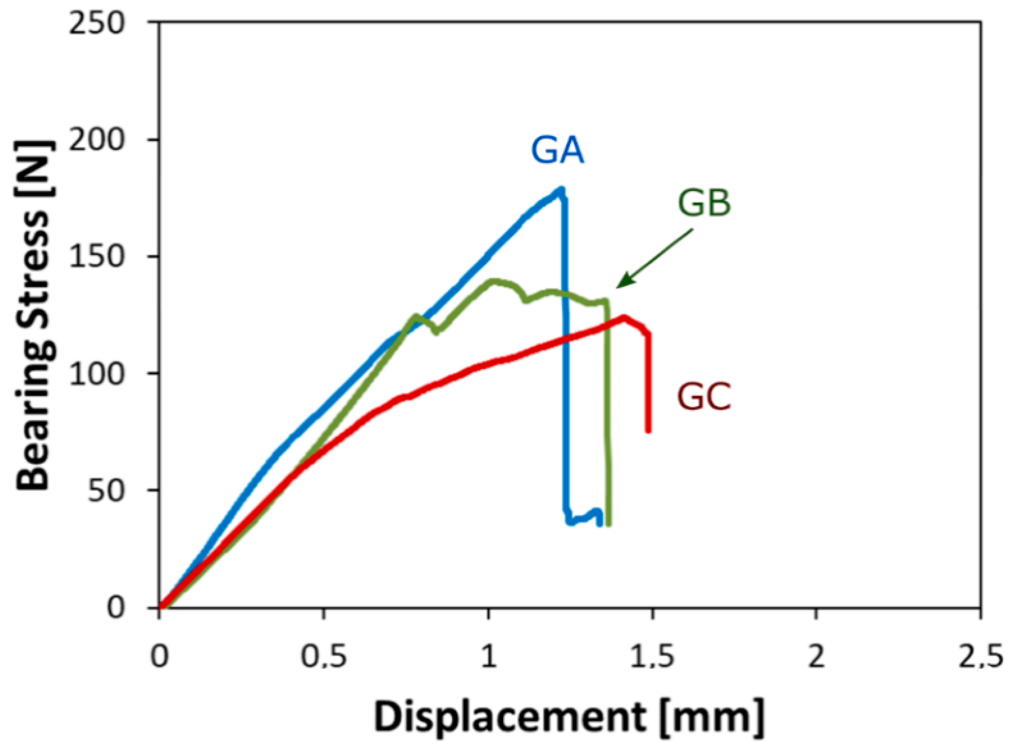
Figure 4 shows the stress versus displacement curves for all batches with diameters and edge distances 8 mm and 14 mm, respectively. It is possible to note that at varying aging cycles, the maximum stress gradually decreases. In particular, reductions of 19% and 28% were observed for batches GB and GC, respectively, due to the salt/fog exposure.
At the same time, a softening effect, due to salt/fog aging, can be argued by evaluating the reduction of the bearing stress/displacement slope at low displacements (indirectly associated to the pinned joint stiffness). In particular, after 60 days of aging (sample GC-8-14-15), the glass composite laminate is characterized by a maximum bearing stress of 123.8 MPa, compared to the GA-8-14-15 unaged sample that showed a bearing maximum stress of 171.1 MPa. Furthermore, a slight increase of the displacement at failure can be observed comparing aged and unaged samples, although this variation can be considered not mechanically significant. After 60 days of aging GC sample showed a displacement at failure about 25% longer than GA-unaged one.
Due to the exposure to a severe environment, such as marine conditions, the glass-fiber reinforced plastic tends to absorb a great amount of water because of preferential pathways triggered by voids and cracks within thermoset matrix [
31,
32]. Thus, water penetrates at the fiber–matrix interface, stimulating a fast epoxy-matrix softening. This phenomenon initially leads to a reduction in interfacial adhesion, and subsequently, to a decrease in the strength and stiffness of the composite laminate, as can be identified by comparing the stress/displacement curves of unaged and aged laminates reported in
Figure 4. These results are in agreement with a wide literature that confirms that the mechanical performances of glass-fiber composites are strongly influenced by exposure to humid or wet environmental conditions [
32,
33,
34].
Further information can be argued evaluating the bearing stress evolution at increasing edge distance for pin loaded laminates with a hole diameter
D = 8 mm and width
W = 15 mm (
W/
D = 1.875) for all aged batches (
Figure 5). At short edge distance,
E, a premature fracture occurs at a low stress level, due to shear out mechanisms regarding the limited distance of the hole from the specimen free edge. Afterwards, the bearing stress gradually increases at increasing the edge distance up to 8–10 mm. Above this threshold, a slight change in the slope trend can be shown for all batches. In this region, a main cleavage fracture mode takes place. Finally, for an E over 12 mm (
E/
D > 1.5), the net tension mode becomes the predominant failure mechanism and the bearing stress trend reaches a plateau region (stage III).
As is widely known [
12,
35], cleavage can be considered as a mixed mode between shear out and net tension because it is caused by a combination of shear and tensile stress out [
12]. Frequently, it starts from the laminated edge rather than in the area surrounding the hole [
5]. Due to the catastrophic nature of shear out and net tension mode, cleavage can also be considered a premature and sudden fracture mode, leading to noticeable and abrupt reduction of the joint load capacity. Moreover, it is worth noting that when a pinned laminate fails thorough this mixed mode, the mechanical strength of the joint is still influenced by edge distance (
E), even if a lower slope variation can be observed in comparison to the slope variation found in the shear out region.
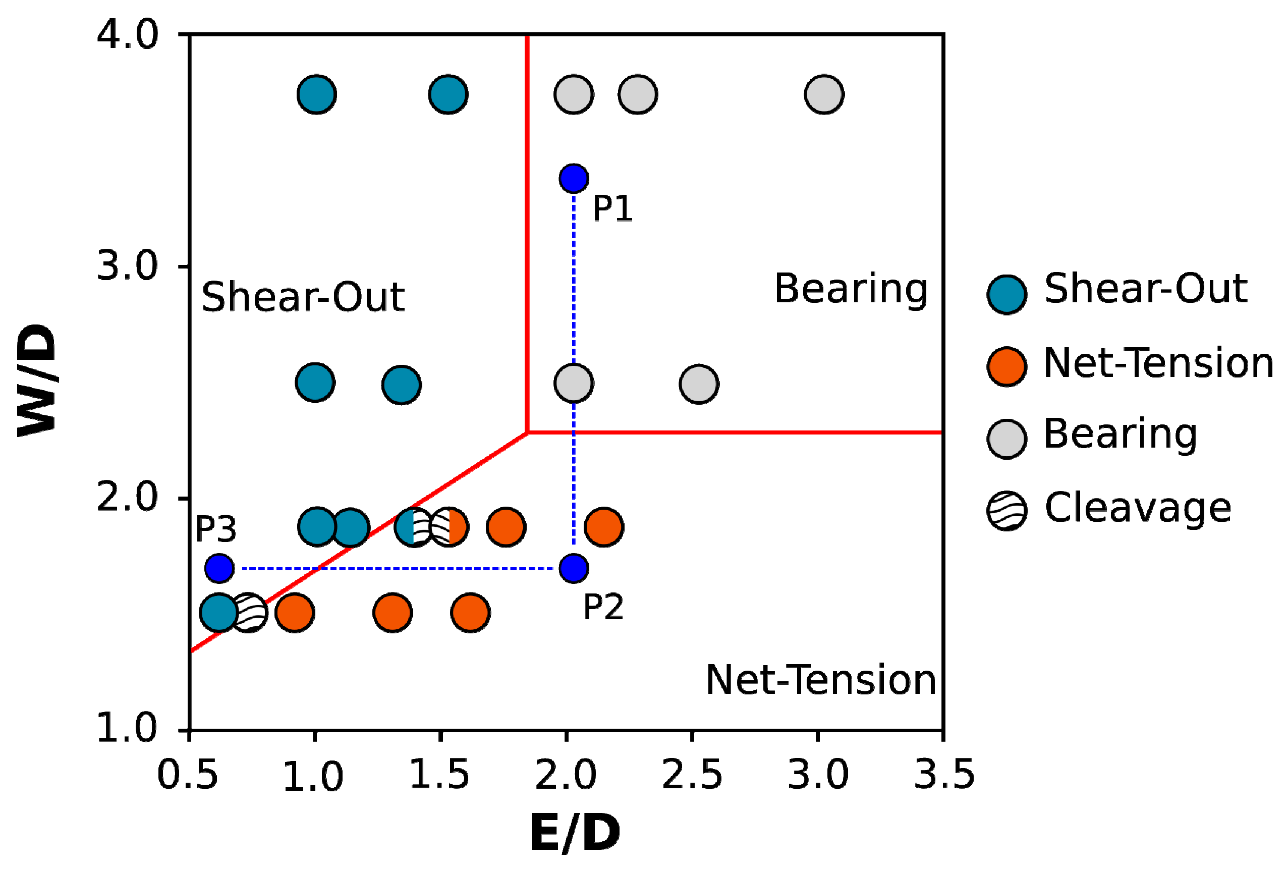
In order to better assess the effect of the joint geometry modification on the failure mechanisms of the pinned joint, a 2D topological failure map of the GC aged glass composite laminates (aged for 60 days in the salt/fog environment), at varying
E/
D and
W/
D ratios (
x- and
y-axes, respectively), is shown in
Figure 6. To better evidence the representative groups of each failure mode, a specific marker color was applied for each observed failure mechanism. Combined color markers are related to mixed failure modes.
The bearing fracture, gray circle marker, becomes the main failure mechanism for high
W/
D and
E/
D ratios (see point P1 in
Figure 6). Although, due to a reduction of
W/
D ratio, maintaining the constant
E/
D ratio (this is achievable making a larger diameter, but keeping the distance of the hole from the edge, E, constant) at point P2 was where a net-tension fracture occurred. In particular, a transition from bearing to net tension failure mode can be highlighted at about
W/
D = 2.2. When hole diameter
D is increased, maintaining at the same time-constant laminate width
W, the reduced cross section induces a higher stress concentration. That, in turn, favors a premature fracture of the sample through net tension mode afterward, inducing a reduction of
E/
D ratio, and keeping constant the
W/
D ratio (this is achievable applying a lower edge distance, preserving a constant diameter). Then, point P3 is reached, where a premature fracture due to shear-out mechanisms was observed. Indeed, lowering the
E value, and keeping constant the other joint geometrical parameters (i.e.,
D and
W), makes the distance of the hole from the sample’s free edge decrease. The reduced shear cross section favors a premature shear out fracture, even if a mixed mode (i.e., cleavage) can be observed, as evidenced by the transition region at the boundary between net tension and shear out fracture mechanics [
5]. When this combined fracture mechanism happens, it means that neither net tension nor shear out mode is predominant [
5,
12].
The bearing mode can be defined as the preferred option in the joining design considering that it is a progressive damage mechanism, allowing one to identify the damage activation before its final fracture. This allows us to define damage-risk procedures in order to qualify warning protocols during the service life of a composite structure. Vice versa, net-tension and shear-out mode are premature failure mechanisms that occur catastrophically, not allowing one to supply a damage warning. This amplifies the risks of relevant and improvised damages to the structure; thus, making these two fracture mechanisms not desired at the joining design stage. By considering that bearing failure cluster is located in the top right area of the map, high values of W/D and E/D ratios are required to avoid premature fracture for the chosen pinned-joint geometry.
Nevertheless, the material excess needed to guarantee the stability of the joint is certainly a limit for the effective development of composite structural components. Hence, a forecast approach aimed to predict the joint damage as a function of its geometrical parameters can be considered crucial for the designers. In this context, the proposed failure map represents a useful and proper tool aimed to a more correct design of the pinned composite joints, due to its simplicity and adaptability to the environmental aging conditions in which the structure operates.
Based on the geometrical characteristics of the joint, it is possible to theoretically forecast the occurring fracture mechanism by using the relationship between bearing, net tension and shear out fracture load As already showed in our previous papers [
12], a theoretical forecasting of the failure mode of structural composite joints can be done, starting from their geometric parameters. In more detail, three fracture transition lines can be drawn in the
E/
D–
W/
D plane, aiming to identify three distinct zones, each of them representing the dominating area of a specific failure mechanism (see
Figure 6). The straight lines were identified as equalizing the threshold failure loads for each fracture mechanism, calculated on the basis of the experimental values of stress limits for bearing, net tension and shear out, according to approach proposed in [
14]. These lines are overlapped in experimental data for GC samples reported in
Figure 6, showing a good fitting between theoretical and experimental results providing that this simplified model could be able to forecast damage mechanisms in pinned glass composite joints. In particular, based on theoretical model it is shown that, for a 60-day aged glass laminate,
E/
D and
W/
D ratios must be set higher than 1.84 and 2.28, respectively, to guarantee the bearing mode as predominant failure mechanism.
As discussed above, net tension and shear out can be considered premature and catastrophic fracture mechanisms that; for these reasons, they must be avoided when a joint is designed. Consequently, a sharp reduction in joint performances takes place. However, it is worth noting that the pinned joints failed through a bearing failure mechanism; thus, evidencing its maximum resistance, due to the progressive and not the catastrophic nature of the latter failure mode.
Several damage mechanisms play a relevant role in the triggering of failure by bearing mode of pinned composite laminates [
36] (e.g., micromechanical fiber buckling in the laminate [
37] or delamination damage [
38]); thus, promoting a gradual and not abrupt fracture that prevents undesired faults.
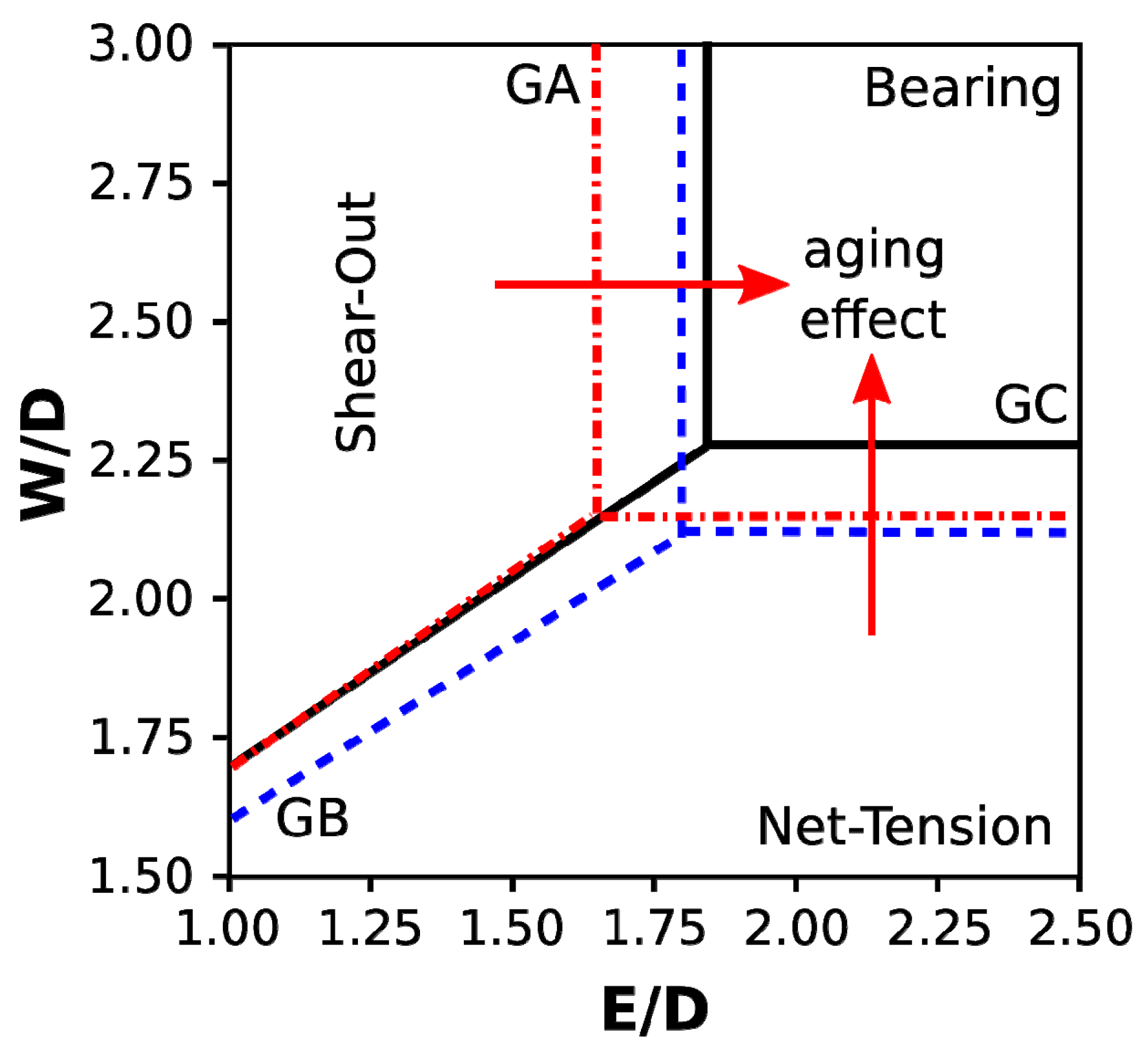
Relevant information on how the salt and mist chamber’s aging conditions affect the damage to fiberglass joints can be traced by correlating the evolution of fracture line transitions at varying aging times. In this sense,
Figure 7 shows the failure map in the
E/
D versus
W/
D plot for the pinned-glass composite joints with increasing aging time.
The composite laminate degradation, imposed by the critical salt/fog environment to which it was subjected, led to a gradual reduction of the bearing region, located in the upper right corner of the map. In particular, for GA samples (unaged specimens), the bearing region was identified in the E/D and W/D ratios 1.64 and 2.15, respectively. Instead, as previously discussed, due to 60 days of aging in a salt/fog environment, those threshold values increased up to 1.84 and 2.28 respectively. This indicates that a reduction of threshold geometrical ratio of about 10% can be identified for glass composite joints aged in the critical environmental conditions.
After only 30 days of aging (blue straight lines, GB batch), the W/D threshold that defines the transition between net tension and bearing is almost constant compared to unaged one (i.e., from 2.15 to 2.12). Instead, a relevant modification of E/D threshold ratio can be observed (about 9%, from 1.64 to 1.80). This indicates that shear-out is the mechanism of fracture that is most affected by critical environmental conditions at short aging times. In fact, analyzing this region for the GA and GB batches shows that a significant increase in its area occurs. This behavior was due to a significant reduction in the fiber/matrix interfacial adhesion, which favors the triggering and propagation of shear cracks in heavy stressed areas.
A further increase in the aging time up to 60 days (i.e., GC batch) favors a net-tension fracture. In this case, long aging time stimulates high water adsorption by glass-fibers, which progressively degrade [
29,
39,
40]. Due to the low hydrophilic behavior of glass-fibers, the high sorption phenomena are triggered by preferential pathways at the fiber/matrix interfaces, induced by debonding, delamination or matrix swelling [
31,
41,
42]. It is worth noting that, initially, the degradation phenomena act at the fiber/matrix interface, causing mainly, a shear-out resistance decrease. Subsequently, due to long aging times, the degradation phenomena more effectively affect the net-tension mechanism. Therefore, the predisposition of the aged joint for these two fracture mechanisms (shear-out and net-tension) takes place, reducing the effective bearing region claimed in the joining design phase.
It is of utmost importance to know that a joint that fails through bearing mode is still able to sustain residual stress even after the beginning of the damage. Unlike in the case of catastrophic failure mechanisms, such as shear out and net tension, when a properly designed joint reaches its maximum strength, it does not experience a sudden and improvised load drop but maintains a quite good mechanical stability. This behavior represents a warning during the service life of a structural joint, indicating the necessity of inspection and maintenance operations.

 ,
, 


