1. Introduction
Concrete is indispensable for restoring/building vital infrastructure (buildings, transportation networks, etc.) required for sustaining the economic growth and quality of life worldwide. Brittleness, exposure conditions, and loading configurations typically result in the initiation and propagation of cracks in concrete and consequently affect its overall performance and longevity. Hence, numerous studies have been conducted to introduce high-performance fiber-reinforced cementitious composites (HPFRCCs) in which fibers are a crucial component to control cracking and enhance ductility [
1,
2,
3]. HPFRCC can be employed in a suite of infrastructure applications such as production of thinner and lighter structural elements, beam-column joints, retrofitting/strengthening of flexural sides of elements, topping of heavy-duty flatwork (e.g., pavements, bridge decks), etc.
HPFRCC incorporating high-volume supplementary cementitious materials (SCMs), such as slag, typically has improved durability with the added sustainability benefit of reducing the carbon footprint of the product [
4]. However, there is still lack of confidence in using higher volumes of SCMs in concrete among various stakeholders, mainly due to performance limitations including delay in setting time and slow strength development at an early age, which adversely affect construction schedules [
5]. Due to their ultrafine nature, nanomaterials (size scale of 1–100 billionth of a meter in any dimension) can vigorously speed-up the kinetics of cement hydration, especially at early ages [
6,
7,
8,
9,
10]. In addition, it has been postulated that a very rapid pozzolanic activity is possible as silicate ions from nano-silica aggregates engage with calcium hydroxide forming pozzolanic calcium-silicate-hydrate gel [
6,
10,
11,
12,
13]. Moreover, nano-silica can accelerate the hydration of cement by creating additional surfaces for early precipitation of hydration products. Additionally, it has been shown that commercial nano-silica sols (originally dispersed to their primary sizes) form small enough agglomerates to impart a filler action in the cementitious matrix [
14,
15]. In addition, when small agglomerates of nano-silica form, water absorption into their ultra-high nano-porosity can reduce the
water/binder ratio in the paste and, thus, improve the microstructure of the matrix [
14]. These effects of nano-silica typically lead to a dense/refined pore structure and contribute to the microstructural development of cement-based materials [
6,
10,
13,
14]. Therefore, their application in cementitious binders (nano-modification) has shown great potential to mitigate the early-age performance issues associated with the use of higher volumes of SCMs and create innovative types of sustainable cement-based products with superior performance. For instance, findings from previous studies showed that addition of 1–6% nano-SiO
2 or 5–20% nano-CaCo
3 by mass of binder has an accelerating effect on early-age properties (hydration, setting time, and strength development) of cementitious systems incorporating 30–50% fly ash or slag [
6,
9,
16].
Recently, it has been shown that cellulose-based nanomaterials [nano-crystalline cellulose (NCC) and nano-fibrillated cellulose (NFC)] can improve the characteristics of cementitious materials [
17,
18]. These sustainable and biodegradable nanomaterials have high surface area and aspect ratio, low density, low thermal expansion coefficient, and low cost compared to other nanomaterials (e.g., nano-silica, carbon nanotubes) [
17,
19]. For instance, 0.5% NCC by mass of the binder improves the hydration process in the matrix due to its hydrophobicity and reactivity of surface hydroxyl groups with calcium silicate phases in cement [
17,
20]. It was reported that up to 0.2% NFC by volume of binder improved the compressive (up to 15% relative to the reference binder) and tensile capacity (up to 34%), and flexural strength (up to 22%) of normal strength mortar/concrete [
21]. However, there is still a lack of information on the effect of cellulose-based nanomaterials on different types of HPFRCC (e.g., high-strength types) and their interaction in the mixtures with high-volume SCMs or other types of fibers.
Basalt fibers have been used as a reinforcement in cementitious materials due to their mechanical characteristics (strength up to 3000 MPa, modulus of elasticity up to 100 GPa), non–corrosive nature, high thermal resistance, and low cost compared to other types of fibers (e.g., carbon, glass, steel) [
1,
3,
14]. However, degradation of basalt fibers in alkaline media, such as cement-based matrices with high pH, was reported due to reactions between the silicate component in the fibers and alkaline pore solution, which had negative effects on the strength and durability of the hardened cementitious matrix [
1,
14]. Therefore, a novel form of encapsulated basalt fiber strands in a protective polymeric resin (e.g., epoxy, polyamide, etc.) known as basalt fiber pellets (BFP) has been recently introduced to mitigate this performance risk [
3]. HPFRCC incorporating BFP may offer a viable option for a suite of applications, which warrants focused research in this direction.
Despite the remarkable independent performance of nanomaterials, some studies showed that the combined effect of using fibers and nanomaterials may adversely affect their workability [
22,
23,
24]. However, this reduction in workability can be offset with the use of a high dosage of supplementary cementitious materials (SCM) [
24,
25]. Other parameters such as strength, ductility, and durability may also be affected if the optimum fibers dosages and nanomaterials are not used to avoid the agglomeration of fibers/nanomaterials [
25,
26,
27]. Such agglomeration of the nanomaterials on the fibers may lead to a reduction in the bond between the matrix and the fiber, which leads to a reduction in the bond between the matrix and the fiber, pulling out of the fiber.
Concerted efforts at the University of Manitoba led to the development of nano-silica modified slag-based (50%) HPFRCC, meeting Category 1 high-volume SCM concrete [
28], comprising BFP [
3]. However, further aspects such as binder formulations including bio-based nanomaterials still require exploration. Hence, the current study investigated the performance of composites incorporating NCC and NFC, and their interactions with the base binder and BFP. The effects of these key parameters were evaluated by experiments and statistical modeling. Data from this study are crucial to informatively assess the suitability and resiliency of these innovative composites for infrastructure applications (i.e., overlays, partial depth repairs, strengthening, and shear key bridge joints) requiring balance of strength, ductility, and longevity.
2. Materials and Methods
The Response Surface Method (RSM), based on Face-Centered Composite Design (FCCD), was used to evaluate the influence of mixture design parameters on the performance of composites. Three parameters adopted in the developed models were as follows: nano-particle types (NCC, NS), NFC dosage, and BFP dosage. These parameters were investigated at two levels (1 and −1) representing the factorial part of the model. To improve the accuracy of predicting the response space, a central point, at the intermediate level (0), for each factor was included in the developed models to capture the quadratic effect of each variable, if any. Furthermore, the central point was repeated three times to improve the overall reliability of estimators as well as account for the models’ experimental error. Hence, 15 mixtures were cast to establish the models which consist of the factorial part (23 = 8 mixtures), the axial part (2 × 3 = 6 mixtures), as well as the central point mixture.
The mixtures had a constant total binder content of 700 kg/m
3 and water-to-binder ratio (
w/b) of 0.3 [
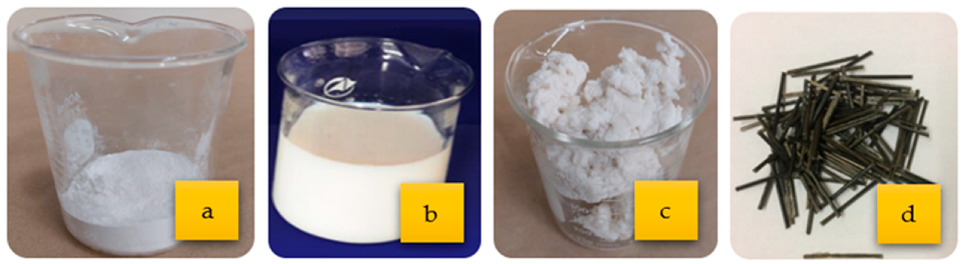
3]. NCC and NS and their combination were added to the base binder at a range of 0–0.1% and 0–6%, respectively. The NFC dosage had a range of 0–0.5% (addition to the mass of the binder), while the BFP dosages were in the range of 0–4.5% (by volume of composite).
Figure 1 shows an example of NCC, NS, NFC, and BFP.
Table 1 lists the adopted variables’ dosages and corresponding codes in the models. The dosages of slag, cement, NS, NFC, NCC, and BFP were chosen based on previous studies [
1,
6,
29,
30] and trial batches. The independent responses modeled were as follows: initial (IST) and final (FST) setting times, 7- and 28-days compressive strengths, flexural toughness, and resistance to freezing-thawing cycles (durability factor), which represent the composites’ fresh, hardened, and durability properties.
The base components of the binder were General Use (GU) cement and Grade 100 slag, which meet CSA-A3001 [
31] requirements. A water-based NS solution, with a 50% solid content of SiO
2 particles, was also used. The specific gravity, mean particle size, and surface area of the used nano-silica were 1.4, 35 nm, and 80 m
2/g, respectively. The NFC used was produced via mechanically refining Kraft pulp derived from softwood trees, while NCC cellulose was extruded chemically by hydrolysis. The NFC used was in wet form, with 20% solid content. The BFP consisted of 16-μm basalt roving encased in polyamide resin with the fiber component accounting for 60% of the pellet’s composition.
Table 2 lists the properties of NCC, NFC, and BFP. The composites were produced using locally available river sand that had a continuous gradation of 0–600 µm with a fineness modulus, absorption, and specific gravity of 2.9, 1.5%, and 2.6, respectively. A high-range water-reducing admixture (HRWRA) based on polycarboxylic acid and complying with ASTM C494 [
32] Type F was added to achieve a flow diameter of 180 ± 20 mm (ASTM C1437 [
33]). In addition, an air-entraining admixture complying with ASTM C260 [
34] was incorporated in all mixtures to achieve a fresh air content of 6 ± 1%.
Fifteen mixtures were cast, cured, and tested. An ID was given for each mixture, where one or more letters identify the type of fibers used followed by a number indicating the dosage. These letters are defined as follows: B-Basalt fiber pellets (B) and NFC-Nano-fibrillated cellulose. The letters designating the nanoparticles are S for NS, C for NCC, and SC for NS+NCC. The mixture IDs, coding, and proportions are listed in
Table 3.
Constituent materials were mixed in a mechanical concrete mixer at a speed of 60 rpm. According to trial batches, a specific sequence of mixing was adopted to produce homogeneous mixtures. Firstly, the dry constituents were mixed, and then the water, admixtures, and NCC and/or nano-silica were added while mixing until the composites achieved uniformity. The BFP were subsequently added, and the ingredients were mixed to ensure that the pellets were distributed evenly and covered with paste. Once a uniform consistency was achieved, the NFC was added, and the mixing continued for 5–7 min. The entire process took about 14–17 min. After casting the composites in molds, all specimens were consolidated using a vibrating table. Polyethylene sheets were used to cover the surface of the specimens for 24 h. Afterwards, the specimens were demolded and cured in a standard room maintained at 22 ± 2 °C and relative humidity of more than 95% until testing.
The fresh properties of composites were assessed by the setting time test following ASTM C403 [
35]. Fresh mortar without pellets was placed in a container at room temperature, and the penetration resistance was determined by standard needles at regular time intervals. The compressive strength of the composites was evaluated by testing triplicate cylinders (100 × 200 mm) at early- and later-ages (3 and 28 days) according to ASTM C39/C39M [
36]. In addition, the flexural behavior was determined at 28 days by testing triplicate prisms (100 × 100 × 350) according to ASTM C1609 [
37], using a servo-controlled closed-loop, where the displacement rate relied on the measured net mid-span deflection of the prisms. The flexural performance was assessed based on the first-cracking/peak strength, residual strength at spans
L/600 (0.5 mm) and
L/150 (2 mm), and toughness, which was calculated as the area under the load-deflection curve up to a deflection of 2 mm.
After 28 days of curing, the resistance of the different mixtures to freezing-thawing cycles was evaluated based on the durability factor (
DF) of triplicate prisms (75 × 75 × 285) mm as stipulated by ASTM C666 [
38], Procedure A, which was calculated using ultrasonic pulse velocity (UPV) with 54 kHz transducers [
39]. In addition, the penetrability of selected mixtures was assessed by performing a fluid absorption test to corroborate the findings from the freezing-thawing test. The test was conducted based on a test procedure introduced by Tiznobaik and Bassuoni [
40] on triplicate concrete discs (75 × 50 mm), which were dried (50 °C and 40% RH), vacuumed (85 kPa), and submerged in a 4% calcium chloride (CaCl
2) solution for 6 h to determine the absorption percentage of the solution into the composites.
The thermogravimetric (TG) analysis was conducted at a constant heating rate of 10 °C/min on powder samples that were extracted from the composites to evaluate the hydration and pozzolanic activities by monitoring the portlandite (CH) quantities in the cementitious matrix up to 91 days. Moreover, associated scanning electron microscopy (SEM) was performed on fracture pieces, which were extracted from untested specimens at 28 days and coated with carbon to improve their conductivity for imaging.
3. Results and Discussion
3.1. Derived Statistical Models
The obtained test results, listed in
Table 4, for the cementitious composites’ responses were statistically analyzed including fresh properties (initial [IST] and final [FST] setting times), early-/later-age strength (3 [
f’c 3d] and 28 days [
f’c 28d] compressive strengths), flexural performance/ductility at 28 days (toughness [
T]), and resistance to frost action (durability factor [
DF]). All responses followed a general model, which can be expressed by the following:
where,
y is response;
Xi: is the independent variable;
β0 is the model intercept (constant);
βi (i = 1, 2, 3) are linear regression coefficients of each factor;
βij (i = 1, 2, 3; j = 2, 3; i > j) are interaction regression coefficients of each factor;
βii (i = 1, 2, 3) are quadratic regression coefficients of each factor; and
ϵ is the random error for uncontrolled factors.
All responses were mapped based on the input parameters, which were utilized to determine the coefficients of the models following a non-linear regression analysis (polynomial function). The presented equations (Equations (2)–(7)) are expressed in terms of the significant factors and their interactions, which were determined using the analysis of variance (ANOVA) method. A factor is considered significant if its probability is lower than 0.05, which means that there is less than a 5% chance (or 95% confidence level) that a tested response surpasses the value of the specified coefficient. Accordingly,
p-values > 0.05 indicate that a factor has an insignificant effect on the measured response; thus, they were eliminated from the equations. This criterion maximizes the models’ coefficient of determination (
R2) [
41], which was above 0.91 for all responses. The models’ best-fit responses were generated using a statistical analysis software [
42].
Predictions for a response at specific values of each element can be made using these equations, which are expressed in terms of coded values. By comparing the coefficients of the elements, coded equations can determine the relative importance of the factors. Indeed, the models’ validity is limited by the high- and low-level factors (+1 to −1) of the experimental variables. To illustrate the interactive relationships among the different variables, three exemplar graphs were plotted from each response, where the effect of the high and low levels of each factor can be visually captured.
3.2. Setting Time
The results of IST and FST varied between 3.3 to 6.5 h and 5.1 to 9.7 h, respectively (
Table 4). Despite the high slag content in the composites, the FST for most composites remained below the lower limit of the documented range for binders incorporating high volumes of SCMs, which typically shows FST within the range of 9 to 12 h [
43].
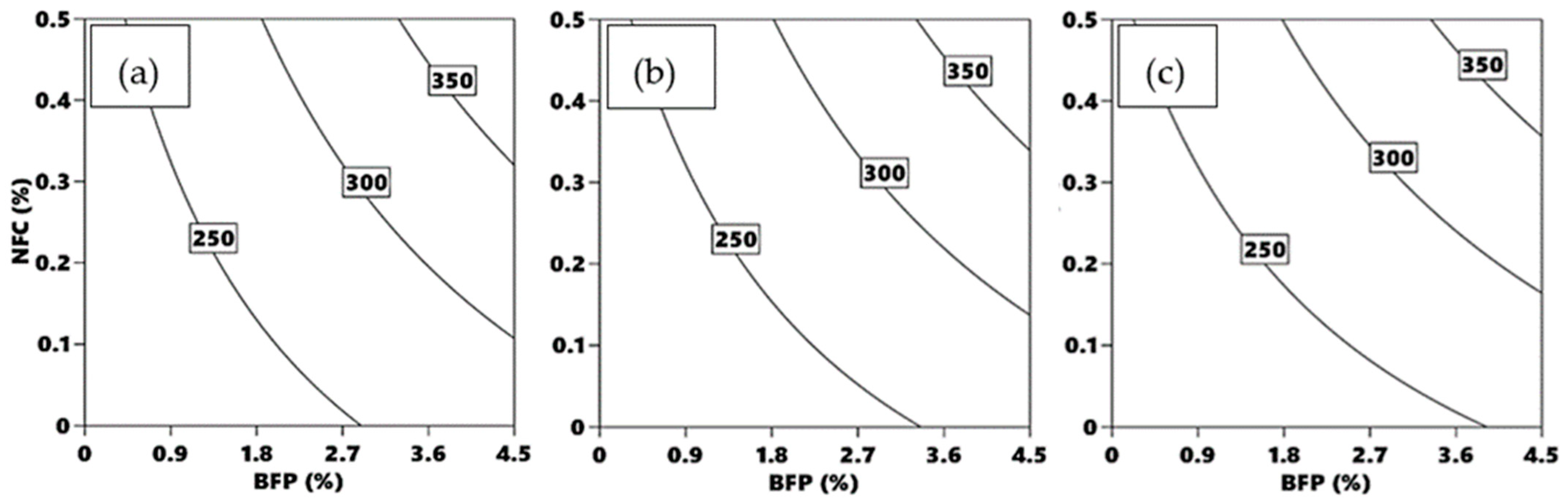
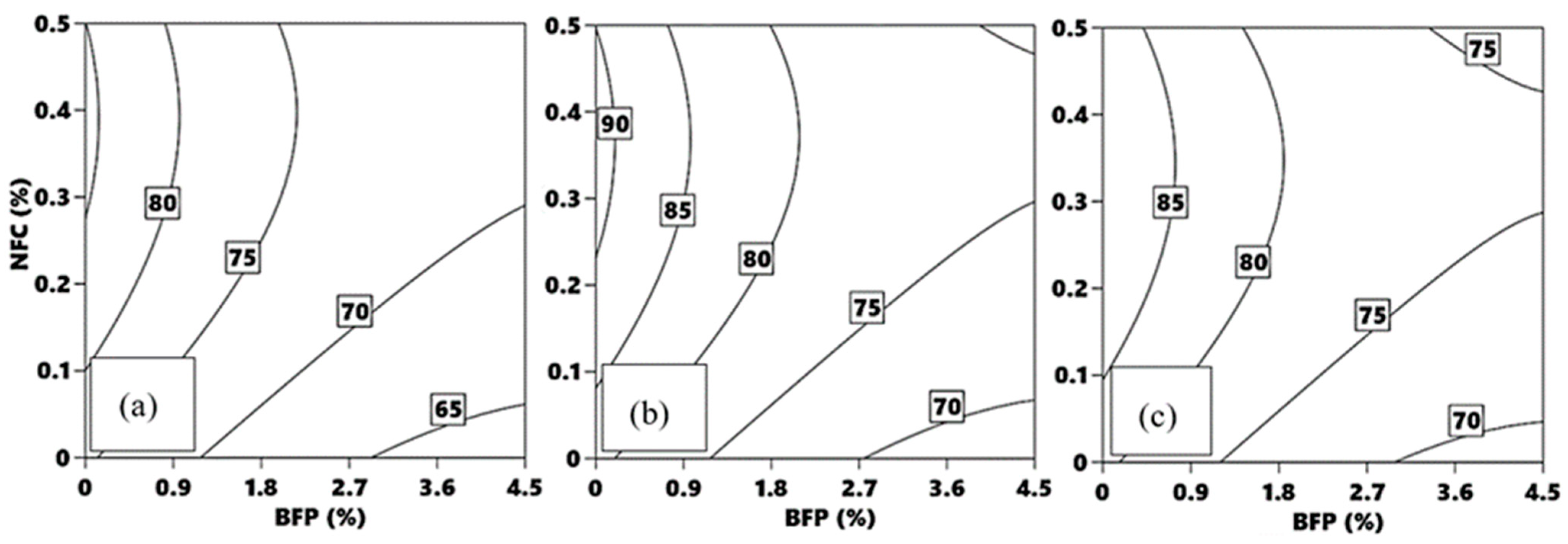
The isoresponses shown in
Figure 2a–c and
Figure 3a–c map the trends from the IST and FST models, respectively. Increasing the dosages of BFP, i.e., the associated HRWRA, led to extending the IST and FST of the composites. For instance, the incorporation of 4.5% BFP in mixture B0-NFC0-S to produce mixture B4.5-NFC0-S increased the IST and FST by 33%. This can be ascribed to the extra amount of HRWRA (1 to 4/m
3, with increasing the BFP dosage) required to maintain the composites’ target flowability, especially when comprising macro-fibers; thus, an increase in the rate of admixture rise to the surface in the fresh state might have reduced the resistance of the superficial layer within the active depth of the penetrating needles in the setting time test. Likewise, the amalgamation of NFC, i.e., associated HRWRA required, in the different composites delayed the setting times but to a lesser extent in comparison with BFP. For example, composite B0-NFC0.5-C achieved longer IST and FST by 18% compared to that of the counterpart composite without NFC (B0-NFC0-C), which were 3.3 h and 5.1 h, respectively.
Although the type of nanoparticles used herein was not a significant factor affecting the skeletal rigidity of the composites, the presence of these materials was essential to achieve acceptable hardening rates through different mechanisms, as will be presented in the TG section, especially with the coexistence of high dosages of a latent hydraulic binder (slag). These patterns align with the results of previous studies on nano-modified concrete incorporating high volumes of SCMs [
1,
3].
3.3. Compressive Strength
As listed in
Table 4, all composites, which contained 50% slag, achieved compressive strengths of more than 30 MPa at early-age, whilst the 28 days mechanical capacity varied between 62 to 92 MPa, which qualifies the proposed composites for a variety of infrastructure applications (e.g., patch repair and overlays for bridges and pavements). This proves the functionality of the incorporated nanomaterials (NS, NCS, or NC) to mitigate the drawback of using high-volume slag on strength development. As depicted in the isoresponse curves (
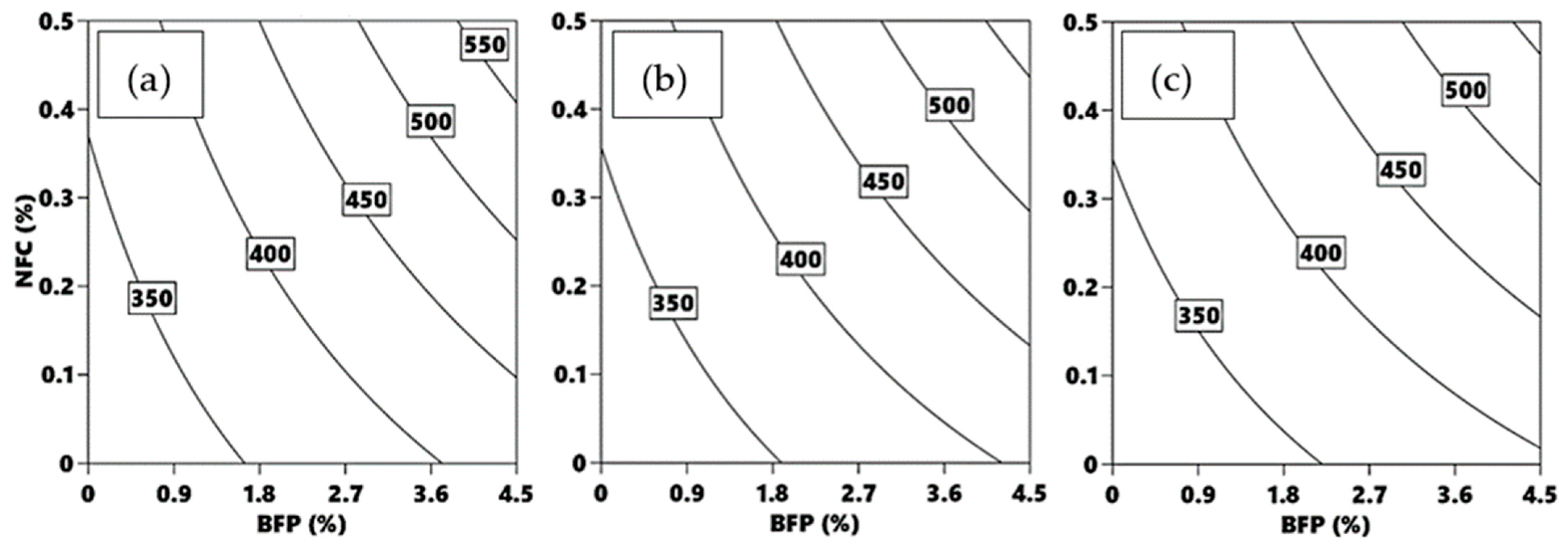
Figure 4a–c and
Figure 5a–c) and the associated statistical models described by Equations (4) and (5), the compressive strengths at both early- and later-ages were significantly affected by the adopted parameters. Both compressive strengths experienced similar statistical significance trends, designated by the magnitudes of regression coefficients. The BFP exhibited the most significant impact on strength, followed by the NFC and nanomaterials type.
The inclusion of BFP notably reduced the composites’ compressive strength values. For instance, adding BFP to composite B0-NFC0.5-C and B0-NFC0.5-S to produce mixtures B4.5-NFC0.5-C and B4.5-NFC0.5-S reduced the compressive strength at 3 and 28 days by an average of 21% and 16%, respectively. This can be attributed to the ITZs created by BFP in the matrix, acting as stress concentrators/weak links, thus reducing its mechanical capacity. In contrast, cementitious composites comprising NFC yielded higher compressive strengths than that of corresponding composites without NFC (
Figure 4 and
Figure 5). For example, the addition of 0.5% NFC by mass of composite B0-NFC0-S binder to produce composite B0-NFC0.5-S increased the 3- and 28-days compressive strengths by 18 and 9%, respectively. This can be ascribed to the short circuit diffusion/internal curing mechanism of NFC, which improves the hydration of the cementitious matrices, as explained in the TG section. This highlights the potential of NFC to alleviate the negative effect of BFP macro-fibers on the composites’ mechanical capacity.
The amalgamation of NC in the composites achieved a slight increase in compressive strength than its counterpart NS and the effect was elevated with the dosage. For instance, composite B0-NFC0-C achieved a higher compressive strength than its counterpart composite B0-NFC0-S as it increased the 3- and 28-days compressive strength by 6 and 13%, respectively. Both NC and NS provide nucleation surfaces for hydrations products to precipitate on at early-age; however, the short internal curing mechanism of cellulose nanomaterials might have achieved better development in the composites’ microstructure.
3.4. Flexural Performance
Table 5 lists the flexural properties including first-peak flexural strength, residual strengths, post-cracking residual strength index, and toughness for all composites at 28 days. The flexural strengths for all composites were in the range of 5.7 to 14.7 MPa, which qualifies them to be employed in various construction applications such as bridge overlays, repair patches, joint fillers, etc. [
4]. The general trends of the tested mix design variables were similar to that of the compressive strength, in the sense that the first-peak flexural strength mainly depends on the mechanical capacity of the cementitious matrix, which is affected by the type of binder and fibers, as described in the Compressive Strength section.
The residual post-cracking strength index (Ri), which assesses the performance of fiber-reinforced concrete (FRC) in bridges, was calculated for each composite. The Ri of composites containing 2.25% and 4.5% BFP was greater than 0.4 and 0.9, respectively. Depending on the application and the layers of cracking-control reinforcement, it is required that a suitable fiber content in FRC is chosen based on Ri to meet or surpass specified values ranging from 0 to 0.30. Accordingly, the developed composites with BFP have acceptable flexural performance for bridge applications.
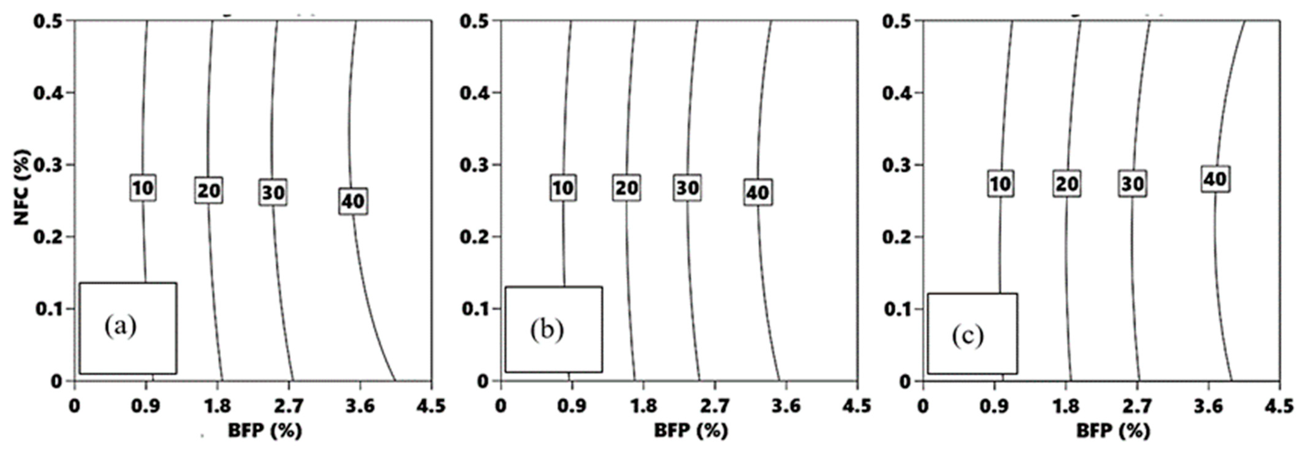
The derived Equation (6) and corresponding iso-response curves (
Figure 6a–c) indicate that the toughness response was significantly influenced by BFP solely. The composites incorporating BFP experienced a significant increase in toughness. For instance, the addition of BFP at dosages of 2.25% and 4.5% to B0-NFC0-S composite to produce B2.25-NFC0-SC and B4.5-NFC0-S composites boosted the toughness from 1.5 J to 26.5 and 43 J, respectively. This can be linked to the effective control of BFP over the spread of macro-cracks and resistance to pull-out, after the peak load was reached, resulting in higher ductility, especially with the higher BFP dosages owing to the abundance of the pellets in the specimens’ failure plane leading to a plateau after the first peak or deflection hardening (
Table 5). Contrarily, NFC had a negligible impact on the composites’ toughness; for instance, the addition of NFC to composite B4.5-NFC0-C to produce composite B4.5-NFC0.5-C increased the toughness by 1 J. Likewise, changing the type of used nanoparticles showed an insignificant effect on the toughness. For example, composite B4.5-NFC0-S attained a toughness value of 43 J compared to 42 J of the counterpart composite comprising NCC (B4.5-NFC0-C).
3.5. Durability Performance
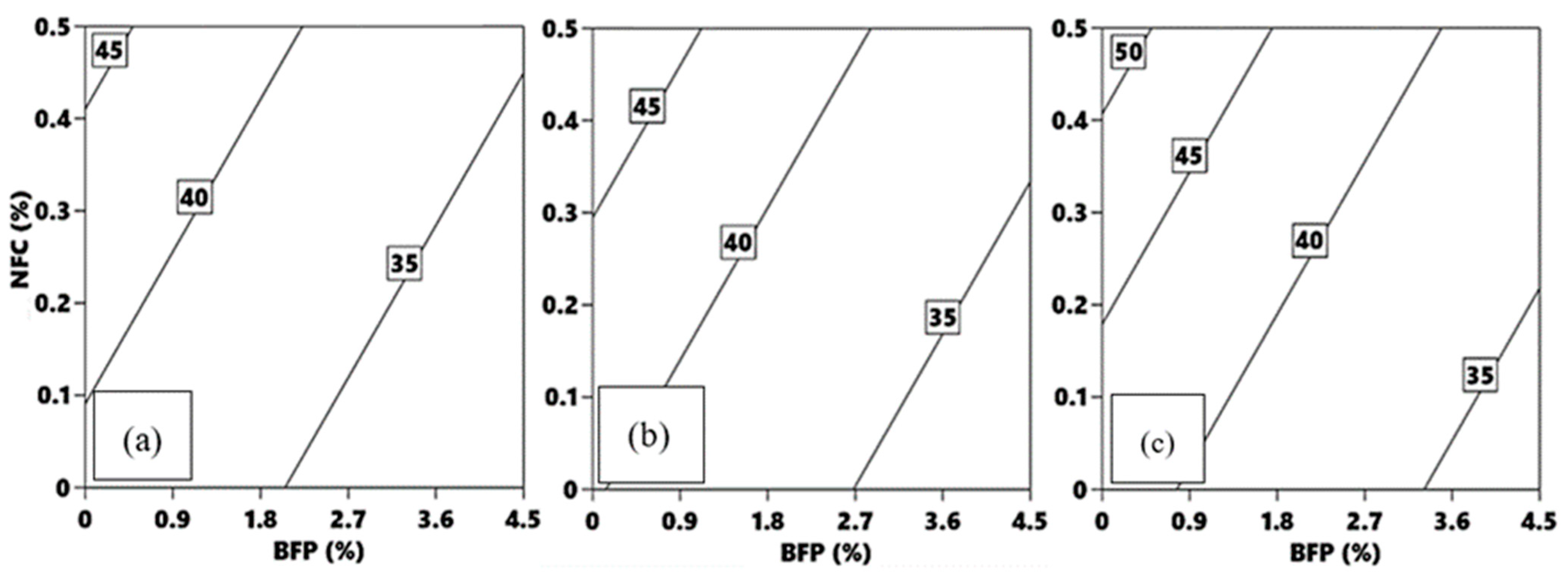
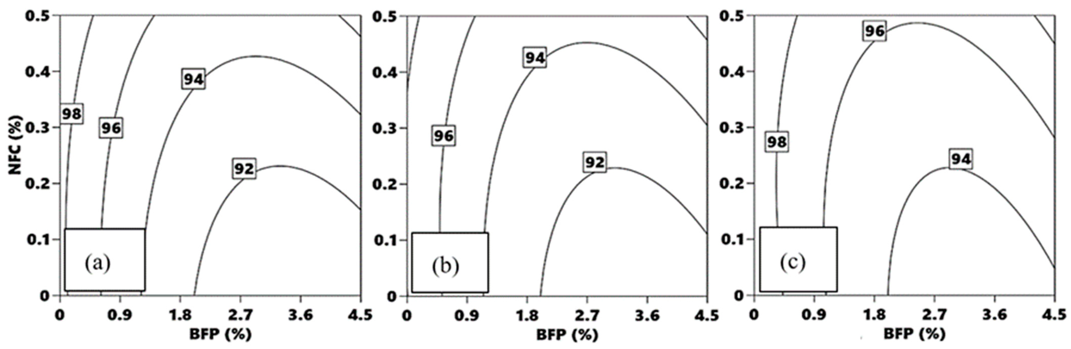
The composites’ durability performance was assessed based on its resistance to 300 cycles of freezing-thawing. The isoresponse curves mapped in
Figure 7a–c and the corresponding Equation (7) show that the BFP and NFC dosages, in order of significance, had a dominant effect on the
DF with regression coefficients of −2.2 and 1.5, respectively.
Composites comprising BFP achieved relatively lower
DF compared to the counterpart composites without pellets. For instance, by adding BFP to mixture B0-NFC0-S to produce mixtures B4.5-NFC0-S, the
DF was reduced by 10%. This can be ascribed to the creation of additional ITZs, which decreased its mechanical capacity [
44]. However, the marginal effects of BFP on the composite’s resistance to freezing-thawing cycles were mitigated by the combination of NFC and BFP to create a hybrid fiber system. For example, composites B0-NFC0-C, B4.5-NFC0-C, and B4.5-NFC0.5-C achieved DF of 100, 93, and 98, respectively, which highlighted the capability of NFC to alleviate the negative effect of BFP due to its physical, chemical, and internal curing effects, which increased the mechanical capacity of the matrix.
Despite the insignificant effect of the nanoparticles type on the composites’ response to frost action, their presence was essential to achieve high
DF values. This can be attributed to the short circuit diffusion mechanism of NC and the pozzolanic/filler effects of NS, which markedly enhanced the composites’ microstructural characteristics as well as the discontinuity of the BFP ITZs. This can be substantiated by the fact that all composites tested herein had a
DF surpassing 90% and exceeding the 60% relative dynamic modulus of elasticity limit stipulated by ASTM C666 [
38], which qualifies them for outdoors exposures in cold regions [
44]. Indeed, the presence of adequate air content of 6 ± 1% was essential to accommodate the hydraulic/osmotic pressures in concrete caused by freezing-thawing cycles [
43,
45,
46,
47]. In addition, the absorption percentages of all composites were in the narrow range of 2 to 2.5% without significant difference, indicating very low penetrability [
40,
46,
47,
48]. This is attributed to the fact that all composites tested herein had high binder contents (≥700 kg/m
3) and low
w/b (0.30), which would make them resistant to fluid ingress and in turn saturation, which is the necessary condition for frost damage of concrete. In particular, NCC, NFC, and NS densification effects improved the resistance of composites to the ingress of fluids; hence, little freezable water was present in the paste, resulting in composites with superior durability to frost action.
3.6. Numerical Optimization
Through numerical optimization, the generated models can be utilized to identify the mix design of cementitious composites that can be used for various construction applications. Accordingly, an exemplar optimization scenario was carried out considering the adopted parameters at the different levels in a manner to yield responses, which fulfill the target application’s performance criteria. Different goals, such as maximum, minimum, none, target, or within a certain range, were assigned to each response to achieve the intended use of the composite. Afterwards, the importance of each goal was graded on a scale of one to five reflecting the importance of each goal, with one being the least desired and five being the most important. Subsequently, a desirability function was calculated, which represents the best compromise that achieves a balance among all target goals through multi-objective optimization. The desirability function has a range from 0 to 1, with 1 denoting the best possible outcome and 0 denoting that one or more responses are beyond the acceptable boundaries.
A scenario was developed, representing the possible use of composites as a repair/overlay in concrete pavements or bridge decks. The criteria aimed to comply with the specifications of the City of Winnipeg (COW) approved repair products list, which stipulates minimum 3 days strength of 30 MPa, minimum 28 days compressive strength of 55 MPa, and a durability factor of 95%. High flexural toughness is also desirable for this application to minimize reflective cracking from substrate concrete. The target criteria for the scenario adopted herein and the corresponding results are listed in
Table 6. The obtained results showed a desirability of 0.84 for this application.
The results of the optimization study demonstrated that using the highest dosage of BFP (4.5%) was essential to obtaining high toughness (48.5 J) to minimize reflective cracking. In addition, NS, NCC, and NFC were obtained at optimized proportions, to produce a composite with a final setting time of 450 min and high early- and later-age compressive strength of 35 and 75 MPa, respectively, with a durability factor of 95%. It is worth noting that the optimized proportions would change from the ones listed in
Table 6, with the target performance criteria depending on the application defined by the user.
3.7. Thermogravimetric and Microscopy Analyses
3.7.1. Effect of Nanomaterials on the Slag-Based Binder
The contents of calcium hydroxide (CH) present in the nano-modified binders versus time are listed in
Table 7. Irrespective of the dosage of nanomaterials, it was observed that the mixtures incorporating NCC had consistently higher CH contents compared to the mixtures incorporating NS in the slag-based binders at early- and later-ages. For example, after one day of curing, the CH contents in mixtures B0-NFC0-C and B0-NFC0-S was 4.11% and 3.86% (i.e., 7% increase), respectively; the amount of CH in the matrix marginally increased when NCC was combined with NFC.
Mixtures incorporating cellulose nanomaterials experienced a rise in CH contents for up to 14 days as they provide nucleation surfaces for the hydration products of cementitious materials to precipitate on. In addition, they have an omnipresence of superficial hydroxyl groups that can attract calcium ions [
29], causing cellulose to adhere to cement and slag particles. Thus, selecting the optimum dosages of nanomaterials and dispersing them in the cementitious matrix is essential to minimize agglomeration and increase the area of cement–slag hydration surfaces. In addition, hydrophilic NCC/NFC, which are intermixed with hydration shells around cement/slag grains, created a network to diffuse water retained by NCC/NFC into the unhydrated core of particles [short circuit diffusion/internal curing] [
9], hence improving the hydration process in the matrix and attaining a higher degree of maturity. This was reflected by the high early strength (above 30 MPa) of these mixtures despite the high content of slag (latent hydraulic binder). After 14 days, the CH contents in the composites comprising cellulose nanomaterials decreased consistently up to 90 days (up to 26% reduction), indicating that NCC/NFC synergistically catalyzed pozzolanic reactivity of slag in the binder through producing more CH during the first 14 days, which was later consumed in the matrix to precipitate secondary C-S-H, densifying the matrix. This conformed to the high strength (above 75 MPa at 28 days), low absorption (less than 2.5%), and improved durability (
DF of 100%) of these composites.
Mixtures incorporating 6% NS alone had a consistent reduction in CH from 1 to 90 days; for instance, B0-NFC0-S had a drop of 40% and 27% between 1 to 28 days, and 28 to 90 days, respectively. A comparable trend was observed for mixtures comprising 6% NS with 0.5% NFC. Ultrafine nano-silica (specific surface of 80,000 m2/g) acted as nuclei promoting the formation of hydration products. Sufficient CH contents (above 3%) in the presence of vigorously reactive nano-silica in the binder material led to rapid consumption of calcium hydroxide at very early age, demonstrating a rapid pozzolanic activity to produce secondary and stiff C-S-H gel in the matrix, which conformed to the high strength results at 3 (38 MPa) and 28 (78 MPa) days. In addition to the particle packing and physical filling effects of nano-silica agglomerates, the long-term pozzolanic reactivity of slag, as indicated by the lower rates of CH consumption between 28 to 90 days, in composites incorporating nano-silica led to densification of the microstructure, as reflected by the low absorption and high durability to frost action. Binders modified with 3% NS with 0.05% NCC (e.g., B2.25-NFC0-SC) benefited from the synergistic effects of improved hydration and pozzolanic reactivity (concurrent process of CH production and consumption to precipitate additional cement gel), especially with the addition of 0.5% NFC (e.g., B2.25-NFC0.5-SC), which achieved high strength (above 40 MPa and 75 MPa at 3 days and 28 days, respectively) and high resistance to freezing-thawing cycles (DF of at least 95%).
3.7.2. Effect of BFP
When BFP was incorporated into the composites, it resulted in decreasing the compressive and first-peak flexural strengths of composites, which are governed by the matrix features. This effect was attributed to the formation of additional ITZs in the matrix around BFP, creating stress concentration and thus reduction of capacity. However, this adverse effect was partially offset with the addition of NC and NFC, owing to the nucleation and internal curing effects that enhanced the degree of maturity of the matrix, as explained in the TG section. In addition, graded NFC could bridge micro-cracks in the matrix and further increase its capacity, as observed in the compressive and flexural strength trends.
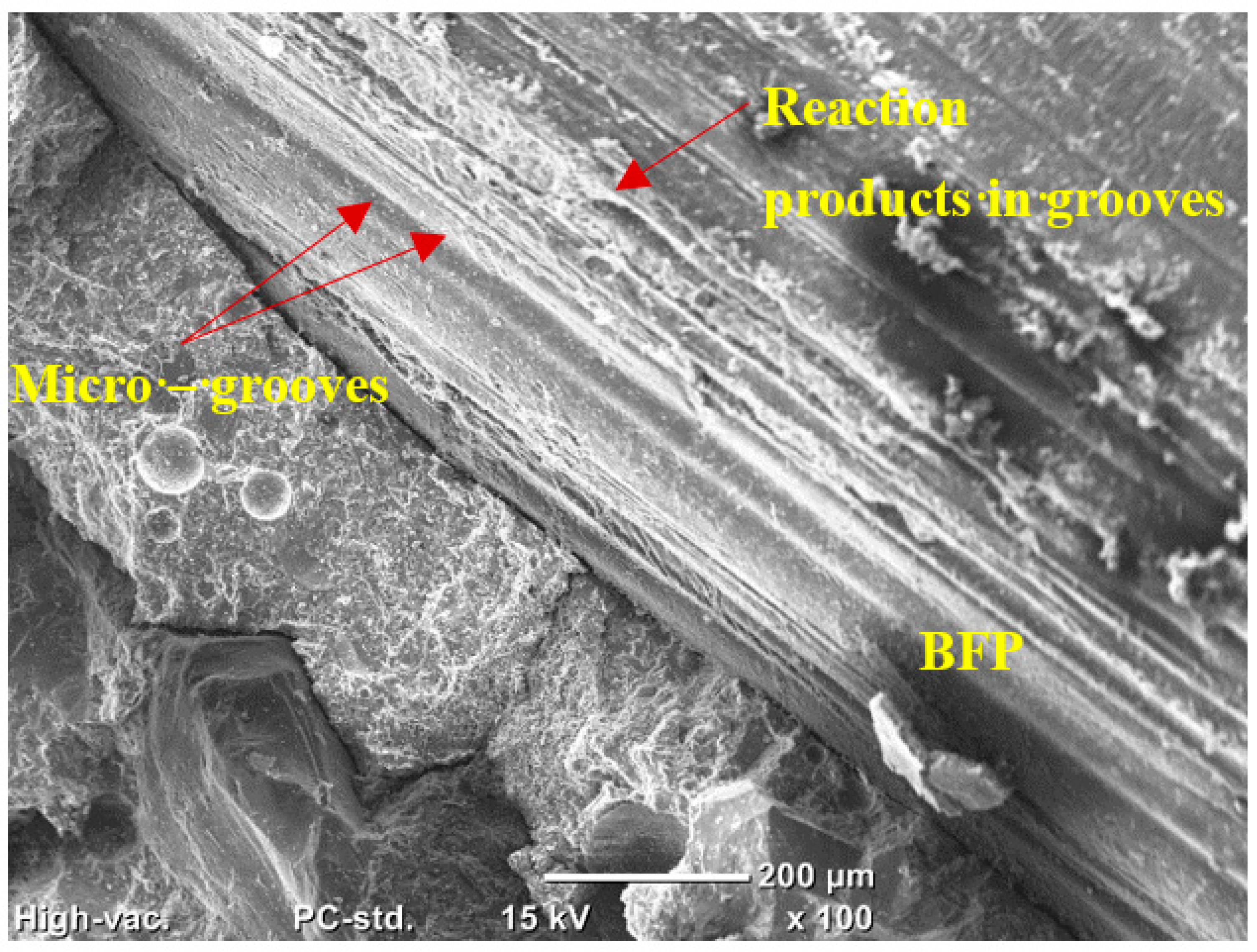
After the peak load/first cracking, BFP had a positive effect on enhancing the post-cracking behavior of composites. The pellets were successful at restoring the load-bearing capacity experiencing a plateau or strain hardening with increasing the dosage (
Table 5). This can be ascribed to the presence of micro-grooves along the surface of the pellets, creating an efficient interlocking mechanism between the cementitious matrix and pellet’s interface and resulting in a greater surface area of contact between them. EDX was used to calculate the calcium-to-silicate ratio (
Ca/Si) of the cement gel on and in the vicinity of micro-grooves. This relation is established to indicate whether the reaction products were hydraulic or pozzolanic as the C-S-H produced through hydration tends to 1.7, while the secondary C-S-H from pozzolanic reactions tends to 1 [
49]. For example,
Figure 8 shows that mixtures incorporating NS (vigorous pozzolanic reactivity) had an average
Ca/Si of 1.1, while mixtures incorporating NCC (enhanced hydration reactions) had an average
Ca/Si of 1.7, which complied with the TGA trends. Indeed, the precipitation of reaction products within the grooves (
Figure 9) enhanced the ductility of the composites by enhancing the bond between the pellets and matrix to resist pull-out, which is the main toughening mechanism.


