Article

Failure Mode Prediction of Unreinforced Masonry (URM) Walls Retrofitted with Cementitious Textile Reinforced Mortar (TRM)

by
Athanasia K. Thomoglou
1,
Martha A. Karabini
1,
Dimitra V. Achillopoulou
2,
Theodoros C. Rousakis
1 and
Constantin E. Chalioris
1,*
1
Department of Civil Engineering, Faculty of Engineering, Democritus University of Thrace, 67100 Xanthi, Greece
2
James Watt School of Engineering, University of Glasgow, Glasgow G12 8LT, UK
*
Author to whom correspondence should be addressed.
Fibers 2023, 11(6), 53; https://doi.org/10.3390/fib11060053
Submission received: 9 May 2023 / Revised: 6 June 2023 / Accepted: 9 June 2023 / Published: 15 June 2023

Abstract

:
The brittle failure of unreinforced masonry (URM) walls when subjected to in-plane loads present low shear strength remains a critical issue. The investigation presented in this paper touches on the retrofitting of URM structures with textile-reinforced mortar (TRM), which enables shifting the shear failure mode from a brittle to a pseudo-ductile mode. Despite many guidelines for applying composite materials for retrofitting and predicting the performance of strengthened structures, the application of TRM systems in masonry walls is not extensively described. A thorough retrospect of the literature is presented, containing research results relating to different masonry walls, e.g., bricks, cement, and stone blocks strengthened with TRM jackets and subjected to diagonal compression loads. The critical issue of this study is the failure mode of the retrofitted masonry walls. Available prediction models are presented, and their predictions are compared to the experimental results based on their failure modes. The novelty of this study is the more accurate failure mode prediction of reinforced masonry with TRM and also of the shear strength with the proposed model, Thomoglou et al., 2020, at an optimal level compared to existing regulations and models. The novel prediction model estimates the shear failure mode of the strengthened wall while considering the contribution of all components, e.g., block, render mortar, strengthening textile, and cementitious matrix, by modifying the expressions of the Eurocode 8 provisions. The results have shown that the proposed model presents an optimum accuracy in predicting the failure mode of all different masonry walls strengthened with various TRM jackets and could be taken into account in the regulations for reliable forecasting.

Graphical Abstract

1. Introduction

Horizontal loads, such as seismic loads and wind, mainly influence the performance of structures made of masonry blocks. Especially in regions where the seismicity is high or where the building structure itself presents increased importance, e.g., monuments, traditional buildings, and cultural heritage, there is a need to upgrade the performance. This paper focuses on reliable predictions of shear failure modes.
The design of in-plane strengthened masonry walls with textile-reinforced mortar TRM systems is described through the analytical models of ACI 549-20 [1], CNR-DT 215 2018 (2018) [2], and Triantafillou (2016) [3]. On the other hand, CNR-DT 200 R1/2012 (2013) [4], Triantafillou (1998) [5], Triantafillou and Antonopoulos (2000) [6], and Eurocodes 6 and 8 [7,8] do not explicitly cover the use of cementitious matrices in fiber-reinforced constructions. The aforementioned existing guidelines do not explicitly cover the use of inorganic matrices (cement-based) in the production of fiber-reinforced composites for construction. Recently, Thomoglou et al., 2020 [9] proposed an analytical model that modifies the expressions provided by Eurocode 8 [8], enables the mortar contribution in the TRM strengthening shear capacity, and predicts the in-plane shear failure modes of unreinforced masonry walls retrofitted with TRM systems with satisfactory accuracy.
Based on the obtained damage, failure modes, and collapse mechanisms in masonry buildings, a database is assembled. It includes experimental results of masonry walls of various substrates (brick, cement, and stone units) subjected to shear and diagonal compression and strengthened externally with composite materials using TRM or fiber-reinforced cement matrixes [10,11,12]. The term matrix refers to the layer that enables the integration of the textile to the substrate and offers protection to the fiber grid against exposure to environmental conditions. Moreover, there is a special focus on the accurate prediction of failure modes. In Section 1 of this paper, a literature review is presented for three different substrates of masonry walls strengthened using the TRM technique, and a database is created containing the experimental results (shear failure modes) of the strengthened walls under in-plane loads and diagonal compression (Section 2). In the next section (Section 3), a proposed model is developed, based on the expressions of Eurocode 8 [8], taking into consideration the contribution of the strengthening mortar of the TRM system to the shear failure modes of the retrofitted walls. The failure modes of strengthened masonry are quantified according to known code provisions and existing models [1,2,3,4,5,6,7,8], as well as the modified model proposed by the authors [9]. The results show (see Section 4) that the accuracy of predicting the in-plane failure modes using the proposed model is, on average, 62% accurate and 32–57% more successful compared to the other models. This research contributes to the understanding of the shear failure modes of unreinforced masonry walls retrofitted with TRM systems, which are promising in terms of enhancing the design guidelines.

1.1. Literature Overview

The pioneers in the study of TRM strengthening systems and prediction models for the shear strength of strengthened brick, concrete, and stone unreinforced masonry URM walls are [5,6,13,14,15,16]. The results showed the strengthened and non-strengthened URM failure modes. The most important studies are further discussed. Different types of textiles (carbon, glass, and basalt) are used for in-plane strengthening using the cementitious mortar as a matrix and also as a welding interface with the masonry units’ substrate. Experimental and predicted failure modes with existing regulations of strengthened URM made of brick, concrete, or stone with TRM reinforcement are presented in the Annex section (Table A1). The thickness of the reinforcement mortar varies according to the different layers when the reinforcement is placed on one or two sides. Although the cementitious mortar composite exhibits adequate resistance and durability in the strengthening systems, some researchers propose an alternative feature for cementitious mortar usage, reducing energy consumption and improving the multi-functionalities of the structures [17,18,19,20].

1.2. Brick Masonry Walls

Diagonal compression tests were conducted on 400-mm-thick tuff masonry walls, double-sided strengthened with one layer of a carbon-fiber-reinforced cement matrix [21], and presented in the sliding failure mode. Additional studies were conducted on nine clay brick walls, three 92-mm-thick control walls, and six strengthened with one and four carbon TRM (CTRM), which were subjected to diagonal compression [22]. The thickness of the strengthening cementitious mortar ranged from 10 mm to 40 mm. The failure mode observed is a combined sliding along the substrate’s mortar joints, tensile rupture of the jacket, and the mortar joints of the substrate, as well as large out-of-plane deformations.
The same experimental tests were carried out by [23] on 140-mm-thick ceramic brick walls strengthened with a carbon textile. The strengthening cement mortar had a 15 mm thickness and was reinforced with polypropylene fibers. The reference walls failed under shear friction, whereas the strengthened walls exhibited diagonal tension failure due to the delamination of the TRM layer. Further in situ diagonal compression tests were conducted on three double-leaf URM walls (one reference wall and one with CTRM strengthening systems with a 20-mm-thick mortar layer) [24]. The URM walls failed due to diagonal cracks in the substrate mortar and in the strengthened mortar in the case of the strengthened masonry walls. Other researchers tested clay brick panels reinforced with carbon and glass grid embedded in a 20-mm-thick fiber-reinforced, pozzolanic, lime-based mortar [25]. The strengthened walls presented with sliding failure along the horizontal mortar joints, with the detachment of the grid at the top and bottom of the wall compared to the brittle failure mode with a single diagonal crack in the reference wall.
A focused investigation on the seismic strengthening of two different types of 250-mm- and 380-mm-thick solid brick and rubble stone URM walls, respectively, (14 references and 36 strengthened walls) with glass TRM (GTRM) and 30-mm-thick lime and cement mortar showed cracks in the mortar coating, while the reference wall showed diagonal cracks following the mortar joints [26]. Reversed cyclic in-plane tests of three large-scale pier–spandrel assemblages and out-of-plane tests on three slender URM walls have been carried out [27]. The failure mode of the strengthened URM walls enhanced the deformation load-carrying ability and altered the failure mode from brittle to ductile. Toe crushing, vertical splitting, and diagonal cracking failure modes occurred in the walls strengthened with the glass TRM (GTRM) system, whereas the as-built walls suffered from bed joint sliding brittle failure.
The effectiveness of retrofitting 24 three-leaf brick URM walls, strengthened via the application of a glass grid in a 25-mm-thick cementitious mortar of an epoxy resin matrix, was investigated by [28]. The walls were subjected to cyclic loads. The consequences of diagonal compression tests on three solid brick URM walls and three strengthened with GTRM applied on both sides were reported by [29]. The shear friction failure mode appeared in the URM, and a splitting crack in the TRM was observed in the strengthened masonry walls.
Ten URM walls were single- or double-retrofitted with high-strength GTRM strengthening systems of different thicknesses and subjected to diagonal tension tests [30]. The thickness of the mortar was 15 mm and 25 mm, and one of them had a textile fiber grid. Toe crushing failure in the compression area was noted, followed by diagonal crushing, with no special need for mechanical bonding to the substrate, in both faces of the strengthened walls. The failure mode was different in the one-face strengthened walls, which were controlled by buckle or out-of-plane deformations.

1.3. Cement Masonry Walls

Carbon textile-reinforced mortar of 10 mm thickness per layer was used by [31] to strengthen the diagonal compression capacity of 92-mm-thick concrete walls. The toe-crushing failure eliminated the shear capacity of the 1-ply and 4-ply strengthened specimens. Subsequently, in-plane shear tests of 150-mm- or 200-mm-thick hollow concrete URM walls strengthened with a 5–8 mm single mortar layer of GTRM, CTRM, and basalt TRM (BTRM) and two layers of BTRM [32]. Although the single-sided TRM system enhanced the shear capacity, altering the failure mode from brittle to ductile, it led to a significant out-of-plane slope.

1.4. Stone Masonry Walls

Shear behavior investigation of 250-mm-thick retrofitted tuff stone panels using a cementitious matrix grid (CMG) was carried out with different layouts of glass TRM with 10 mm or 20 mm of mortar [14]. The retrofitted walls presented shear sliding along the bed joints in various arrangements of the GTRM system. An insignificant impact on the initial stiffness was observed. Another piece of research on the in-plane shear behavior of 250-mm-thick tuff stone panels with half and full-filled joints retrofitted with one or two plies of glass TRM system with 16 mm and 24 mm of strengthening mortar showed toe crushing in both the strengthened and the as-built walls [33].
In situ diagonal compression tests were performed on 560-mm-thick historical rubble stone URM panels, which were strengthened with a glass grid fabric introduced into a 30-mm-thick inorganic matrix of cementitious mortar [34,35]. The strengthened panels exhibited a noteworthy shear capacity improvement when compared to the reference walls and failed in shear friction. A proportional increase in shear strength with the number of layers was observed in 85-mm-thick bricks or 95-mm-thick stone masonry walls strengthened with TRM, while the strengthened walls failed due to rocking [15]. Finally, other researchers applied a 20-mm-thick glass polymer coating to strengthen 500-mm-thick three-leaf stone masonry walls [36]. The strengthened walls, which were imposed to constant vertical and cyclic shear loads, failed under diagonal tension.

1.5. Research Gap and Novelty

To date, much research has examined and documented the in-plane failure modes of masonry structures, and existing standards estimate the failure mode. However, the contribution of the strengthening mortar in terms of the shear strength as well as the different textile materials and masonry substrates, have never been taken into account by the existing models used for in-plane reinforced masonry walls. The novelty of this research is the more accurate failure mode prediction of reinforced masonry that uses TRM and also of the shear strength with the proposed model, Thomoglou et al., 2020, at an optimal level compared to the existing regulations and models, also providing a fundamental advantage regarding other predictions by modifying and improving the expression of Eurocode 8. This is an innovative and vital study as it addresses improving the accuracy of strengthened URM failure mode prediction by categorizing the different masonry units (brick, stone, and concrete), but also the different reinforcement textiles (carbon, glass, and basalt), taking into account the important contribution of strengthening mortar in terms of mortar strains, debonding strains, and mortar thickness. The criterion of accuracy is ±25% convergence to the experimental observations, both for the shear failure mode of the masonry substrate as well as for the retrofitted wall. Although the failure modes of the strengthening system (delamination, rupture, or slippage) are not distinguished in any of the models, the proposed model failure mode predictions agree with 90% of the experimental observations. This research contributes to the understanding of the complex stress–transfer mechanism between the masonry and TRM composite that is of fundamental importance in terms of TRM strengthening effectiveness.

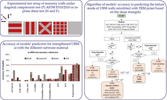
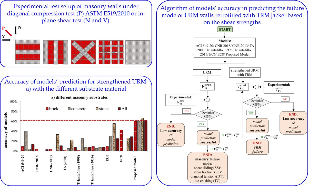
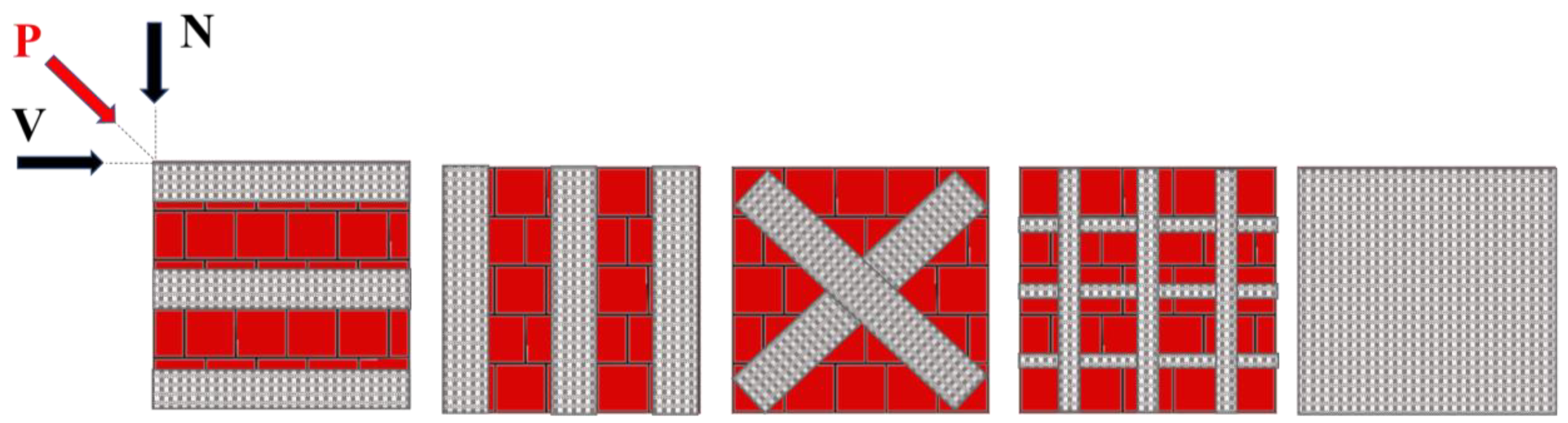
2. Database Assembly

In this study, experimental results taken from the international literature are collected regarding masonry walls. The database assembled includes the experimental results of masonry walls made of different substrates (brick, cement, and stone units) subjected to shear and diagonal compression loads. The specimens are retrofitted with various TRM external strengthening systems. The database includes 128 tests (24 tests of URM and 104 of walls strengthened with TRM jackets) that are included in the works of diagonal compression tests [12,14,21,22,23,24,25,26,27,29,30,31,33,34,35,36,37,38] and shear compression tests [39,40]. The majority of the retrofitted walls are subjected to diagonal compression (93 specimens), and the rest are subjected to in-plane shear compression (11 specimens), as depicted in Figure 1.
The strengthened masonry walls were made of different types of units, e.g., brick (57 specimens), concrete (20 specimens), and stone (27 specimens). The strengthening system consisted of single-sided or double-sided TRM from one to four layers, with their textile thickness (tf) ranging from 4 to 24 mm. The different composite strengthening materials were GTRM (with a modulus of elasticity EGTRM = 36.9–80 GPa), CTRM (ECTRM = 73–240 GPa), and BTRM (EBTRM = 72–89 GPa), orientated in various ways, e.g., horizontally, vertically, diagonally, grid, or full coverage of the exterior surface [41]. The majority of the textile reinforcement layouts coincided with the full coverage of the exterior surface. The masonry specimens provide thickness ranging from 85 mm to 560 mm, with an aspect ratio high/length of masonry walls (H/L) ranging from 0.3 to 3.25, while the masonry unit’s height ranges from 55 mm to 380 mm and the length from 185 mm to 400 mm, with the units’ compression capacity (funit) ranging from 2 to 119 MPa, whereas for the masonry walls, the compression strength (f’m) was 1.27 to 68.25 MPa).
A key observation in several codes and standards [7,8] is that the tensile stress σI is designed by considering a uniform shear stress distribution within the panel, which leads to the below-mentioned central stress state: σy = σx = 0, τ = (1/√2) P/An (An is the cross-sectional area of the wall). Under these hypotheses, the diagonal tensile strength of the masonry fdt is calculated, in practice, as if the panel would be in a pure shear stress state (σIII = −1, for 45° loading slope angle) and is calculated as follows: fdt = σI = 0.7 P/An [42].
The stresses in the middle of a masonry wall, when considering an infinitesimal element, could be defined in terms of compression stresses and shear stresses, which could be translated in terms of principal stresses, as depicted in Figure 2a. In Figure 2b, the three-linear stress–strain curve of TRM coupon tensile strength is presented, where the different phases are followed by each other. The first part is related to the uncracked mortar phase, whereas the second phase is related to the cracks developing. Finally, the load-bearing capacity of the fiber textile corresponds to the third phase [43,44,45,46].
In Table 1, and more representative in Figure 3, the ranges of the experimental values of the shear stresses and strains of binder mortars, masonry walls, strengthening mortars, and the TRM textiles of the strengthened specimens are depicted. Specifically, τεjoint and εjoint are the shear stress and strain of the binder mortar of the URM wall, τεmas and εmas are the shear stress and strain of the URM wall, τεjoint,d, and εjoint,d are the shear stress and strain of the strengthening mortar at the contact level with the masonry wall, τεmortar, and εmortar are the shear stress and the shear strain of the strengthening mortar, and τTRM and εTRM are the shear stress and strain of the TRM textile.

3. Design Models

3.1. Existing Models
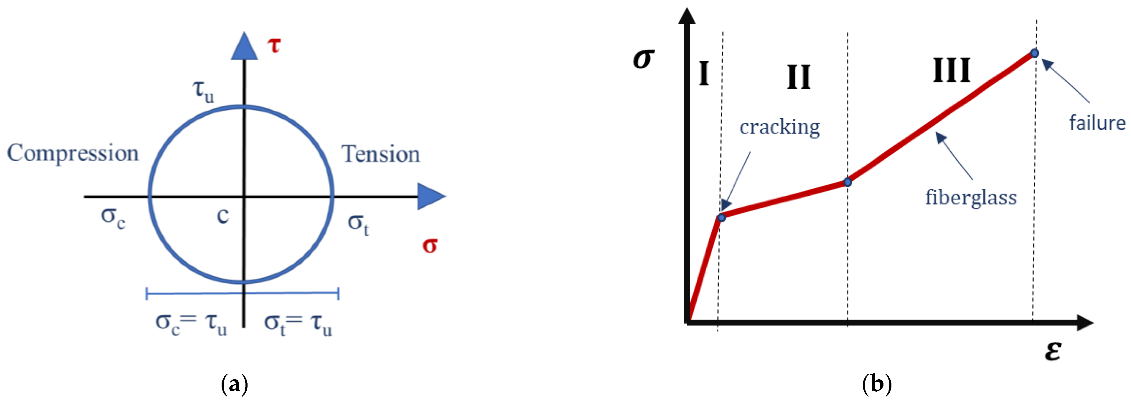
Worldwide design guidelines, as well as many models and semi-empirical expressions found in the literature, quantify the shear strength of masonry panels as the combination of masonry shear resistance and external strengthening system capacity. Part of those models also defines the failure mechanism. Four types of failure modes are recognized for URM walls: (a) shear sliding (SS), (b) shear friction (SF), (c) diagonal tension (DT), and (d) flexural tension toe crushing (TC), as denoted and illustrated in Figure 4, at the failure envelope (Vm–σn), which is designed in terms of shear strength versus compressive stress [47,48,49].
Nine known code provisions and existing models, ACI 549-20 [1], CNR-DT 215 2018 (2018) [2], and Triantafillou (2016) [3], CNR-DT 200 R1/2012 (2013) [4], Triantafillou (1998) [5], Triantafillou and Antonopoulos (2000) [6], Eurocodes 6 and 8 [7,8], and Thomoglou et al., 2020 [9], were chosen to examine failure mode prediction. The examined code provisions include detailed instructions and calculations for the shear capacity of epoxy-based matrix-reinforced URM walls but do not provide detailed instructions in the case of a cement-based matrix.

3.2. Proposed Model

The existing regulations and models estimate the shear strength of the strengthened URM with external reinforcement, considering the assumption that the total contribution to the shear capacity is the sum of two terms, the masonry and TRM. The Thomoglou et al., model innovates in the assumption of the unequal contribution of the external reinforcement, instead giving the coefficient of k for the different strengthening systems (see Table 2):
V Rd =   V m + ( V TRM ) · k
The proposed prediction model takes into account the contribution of the coating mortar to the shear strength and considers the contribution of TRM as follows:
V Rd =   V m + ( V fiber + V mortar ) · k  
The total shear capacity of the masonry contribution Vm is calculated, and is also proposed by the EC8 design model:
V m =   min   ( V sf ,   V dt ,   V f )
where Vdt is the diagonal tension, Vf is the flexural capacity of the unreinforced masonry wall, and Vsf is the shear friction and shear sliding capacity, where shear sliding and shear friction are combined due to the bond strength and friction resistance between the mortar joint and the blocks. Shear sliding and shear friction Vsf are determined according to EC6:
V sf = f v , 0 0.6 · A n
Table 2 describes the values of the calibration factor of the proposed model considering the three types of URM, while each of them is strengthened with glass or carbon-textile-reinforced concrete, providing the factor k value, with variable strengthening contribution (Vfiber + Vmortar).
When failure due to diagonal tension occurs, crack propagation runs through the masonry units. The shear force capacity Vdt, according to EC8, for this failure mechanism is provided in the following equation, using the upper limit 0.065fm to ensure that failure in diagonal tension will occur in the compression area when subjected to a combined normal compressive and shear stress.
V dt = 0.065 · f m · A n  
Because the regulation of EC8 does not differentiate between rocking and the toe-crushing failure mechanism, the shear force capacity of an unreinforced masonry wall, as controlled by flexure under an axial load, may be taken as being equal to:
V f = Ν · l w 2 · h w · ( 1 1.15 · N l w · t w · f m )  
where fm is the compressive strength of the masonry and N is the axial load. The proposed model innovates, compared to the existing models and regulations, in that it assumes the contribution of the strengthening mortar to the total shear strength of the TRM, and it is calculated according to the equation below:
V TRM =   V fiber + V mortar
The proposed model estimates the value of the ultimate tensile strain of the textile reinforcement εfu equal to the fabric or textile debonding strain εffd = 0.27‰. In contrast, existing regulations adopt the value of εfu = 0.4‰. Further, the Vfiber is calculated by the following expression:
V fiber = 2 n · A f · L f · E f · ε ffd  
where Af is the area of the fabric or textile reinforcement by unit width, n is the number of layers of fabric, Lf is the applied textile length over the wall, and Ef is the tensile modulus of elasticity of the cracked TRM. The shear strength of the mortar Vmortar is calculated using the following expression:
V mortar = A mortar · E mortar · ε tm  
where Amortar is the area by unit width, εtm is the tensile strain of the coating mortar, and Emortar is the tensile modulus of elasticity of the cracked mortar of the TRM. The values of each tensile stain εtm of the external cementitious strengthening mortar for different masonry substrates are depicted in Table 2.

4. Results

To examine the models’ accuracy within realistic ranges, a criterion of 25% convergence to the experimental observations was chosen. This means that the predictions do not over or underestimate the shear capacities, and hence, failure mode type. The simple algorithm shown in Figure 5 is followed to categorize the kind of failure mode of every prediction calculated using the models’ equations. The first condition that is examined is the comparison of the predicted shear strength of the URM (Vmpred) with the experimental (Vmexp). The failure mode derives from the condition that the predicted shear strength of the masonry substrate is lower than the experimental observation (Vmpred < Vmexp) within the same convergence range (25%). If the shear criterion is satisfied, the failure mode of the masonry substrate is categorized according to the agreement with the experimental observations and falls into the four characteristic modes (shear sliding, -SS; shear friction, -SF; diagonal tension, -DT; and toe crushing, -TC). Else, if Vmpred > Vmexp, the TRM system is damaged and leads to failure. The success of every model is defined as a percentage of the number of predictions that agree with the experimental observations.
Each prediction result for the retrofitted masonry shear capacity (VRdpred) is compared to the corresponding experimental shear strength taken from the database assembled (VRdexp). A deviation of 25% in terms of the experimental observation was used again as a success criterion of the predictions. If this criterion is not met, then the predicted failure mode presents low accuracy and is not taken into account. In the cases that the deviation criterion is met and the predicted total shear strength is lower than the experimental value (VRdpred < VRdexp), then the model is considered accurate.
The results regarding the predictions of the shear resistance and the failure modes given by the examined regulations and models are presented in the comparative scattering plots (Figure 6). In order to classify the most accurate model for the shear strength of the non-strengthened masonry substrate units (Figure 6a) and of the URM walls retrofitted with the TRM jacket (Figure 6b), scattering plots are used. In these plots, the horizontal axis refers to the predictions, whereas the vertical axis refers to the experimental shear strength. The significance line (ideal estimator) is also plotted, which is known as the identity line. The identity line has a slope of 1, meaning that it forms a 45-degree angle with the horizontal and vertical axis. If the majority of the observations are located below the ideal estimator, this means that the designed models’ predictions of shear strength are greater than the experimental values. As such, the designed models or regulations overestimate the shear strength. In contrast, if the data emerge above the ideal estimator, the design models’ predictions are considered to be conservative. Two more lines are plotted, representing a 25% convergence to the ideal estimator. It is noted that most of the data are included in the range that the two lines create, which means that, in most cases, the predictions estimate the shear strength with an accuracy of ±25%. This level of accuracy is considered desirable since the predictions neither overestimate nor underestimate the shear strength.
The predictions of the CNR-DT 215 2018 [2] design guideline can be considered conservative since the majority of observations were above the ideal estimator (see the X point symbols in Figure 6). On the contrary, the predictions of Triantafillou’s (2016) [3] model, noted with grey solid square point symbols in Figure 6a, seem to overestimate the shear strength of the non-strengthened URM. The predictions of the proposed model are noted with the magenta color point symbols and coincide totally with Eurocodes 6 and 8 [7,8] (denoted as EC6 and EC8, respectively) since the prediction equation is common, presenting the highest accuracy level of all. The model of ACI 549-20 [1] follows in terms of accuracy (see the hollow circles).
The highest level of accuracy regarding the shear resistance of the retrofitted masonry walls is yielded by the proposed model (also see Figure 6b and the magenta point symbols), presenting the smallest deviation from the significance line. The Italian code provisions of CNR-DT 215 2018 [2] are the most conservative. The predictions of the three models of Triantafillou and Antonopoulos (2000) [6], Triantafillou (1998) [5], and Triantafillou (2016) [3] are marked with triangular, square, and solid grey square point symbols, respectively. These three are the less conservative models since an important percentage of the experimental observations presented much lower values in terms of the total shear capacity of the retrofitted URM walls. The predictions of EC 6 and 8 present the same deviation trend from the significance line, noted with rhombus and star point symbols. The proposed models’ predictions not only lay within a smaller limit deviation (±10%) from the ideal estimator but are also closer to the significance line with respect to all other models, denoting their reliability.
The success of the predictions for every masonry wall with different substrates (brick, cement, and stone) retrofitted with various TRM strengthening jackets, e.g., glass or carbon, is presented in Figure 7a. It is observed that the three most successful models for predicting the failure patterns of all the retrofitted masonry walls are the proposed model, Eurocodes 6 and 8 [7,8], presenting 62%, 29%, and 25% success rates, respectively. This means that the proposed model is more accurate than any other existing design model, presenting from 37% to 64% better accuracy in terms of predictions, irrespective of the failure mode type. For the case of the URM with the brick substrate (vertically striped bars) strengthened with different TRM systems, the most accurate predictions are that of Eurocode 8 [8] and the proposed model. The success was 62% and 43%, respectively.
The success level of the proposed model was higher, ranging from 19% to 60% when compared to the rest. For the examined brick masonry walls strengthened with GTRM, 89% of them presented with a failure in the retrofitted system and none of the four characteristic failure modes in terms of the masonry substrate. The GTRM systems exhibited rupture failures, debonding of the grid, or diagonal tension cracking in the mortar layer.
The transmission of failures from the brick interface to the retrofitting jacket denotes that through the shear mechanisms and the capacity of the mortar to bear tensile strains, the stresses are transferred to the composite grid component of the strengthened wall. The proposed model’s success heavily relies on the fixed tensile strain values agreeing with the transition point (εtm = 0.055%), which is the limit of the first crack in the mortar layer. What is more, the contribution of the TRM system calibrated with the factor k (Table 1) is proven to be essential for the success of the predictions.
Similar to the failures of the GTRM system, 52% of the brick masonry walls strengthened with the CTRM system presented three different types of failures: rupture, grid slippage, and the debonding of the composite layer due to loss of adhesion [50,51,52,53,54]. Premature debonding failures of carbon fiber polymer materials have also been obtained in reinforced concrete structural members under shear loading [55,56,57]. The other 48% of the examined specimens failed in the masonry substrate, presenting with toe crushing and diagonal tension damages in the brick units [58,59,60,61].
Similar to the GTRM systems, the proposed model uses a fixed strain value for the transition point of strengthening mortar strain (εtm = 0.112%). The CTRM systems exhibit an increased value of factor k, meaning that after the extensive cracking of the mortar beyond the transition point (εtm), the carbon fiber grid develops tensile resistance, contributing to the shear resistance of the strengthened wall at a greater level than glass.
The results regarding the success of the prediction of the shear resistance and the failure modes given by the examined regulations and models are also presented in the bar charts of Figure 7. The accuracy of the model in terms of retrofitted masonry walls made of concrete units is shown with the grey bars in Figure 7a, as produced from the statistical analysis [62]. The two most successful models are the proposed model and ACI 549-20 [1], which predicted failure patterns with 60% and 40% accuracy, respectively. The models of Eurocode [7] and Triantafillou (1998) [5] follow with lower success levels of 30% and 25%, respectively. The fundamental similarity of the two most successful models relies on the ability not only to predict the shear strength of the wall but also to make a clear distinction in terms of the prediction of the kind of failure based on the shear capacity. Even though this distinction is also met in the Eurocode 8 [8] requirements, the ignorance of the mortar’s contribution to the shear resistance leads to great differences regarding the experimental results. The estimations of all models for the case of stone masonry walls retrofitted with various TRM jackets, the final failure mode of the wall is either a kind of failure of the TRM system or toe crushing of the stone units in the substrate. The mortar layer presents great integration with the existing stone substrate. The proposed model, by taking into consideration the mortar’s mechanical properties, inevitably presents a higher ratio of accuracy, reaching the value of 67%.
The provisions of the models are also categorized according to the masonry substrate failure modes, as illustrated in Figure 7b. Regardless of the material that the masonry units are made of and the type of failure that occurs in the wall substrate, two models provide better success in terms of predictions, and these are Eurocode 6 [7] and the proposed model, presenting 30% and 36% accuracy, respectively. It is noteworthy that the rest of the models present a very low percentage of convergence to the observed failure, ranging from 2 to 13%. The three models that differentiate the masonry failure mode types still do not show a high success level. From the four types of all masonry failures that are identified, only two types can be predicted, and these are diagonal tension (grey striped bar) and toe crushing (diagonally striped bar). It is observed that concrete masonry walls strengthened with the CTRM system and controlled by the toe-crushing failure mode are predicted with small accuracy. The reason that the proposed model presents a low success rate for this type of failure mode prediction is that concrete masonry walls are strengthened with CTRM, despite the fact that the number of specimens is small. As a result, the regulation for toe crushing coming from the EC8 model overestimates the shear strength and should be revised and calibrated. This leads to a low success rate for this type of failure mode and strengthening system.
Shear friction and shear sliding provisions are only provided by ACI 549-20 [1], with no convergence with the experimental results. The proposed model and Eurocode 8 [8] provisions consider shear friction and shear sliding as unique failure modes, and again, no convergence of the predictions with the experimental failures is met. The proposed model presents better success in predicting both diagonal tension and toe crushing; however, it is lower than 30% and 40%, respectively. Although the proposed model is based on the equations and theory of Eurocode 8 [8], the success is expected to be exactly the same for the masonry substrate, which is not met. The final failure mode prediction depends on both the shear strength of the masonry substrate and the retrofitted masonry wall. Given this fact, the proposed model presents better convergence to the shear capacity of the substrate and the strengthened wall; hence, its accuracy is higher than that of the Eurocode 8 [8] provisions.
Regarding the different types of failure modes, there is a small number of experimental results relating to masonry walls that are controlled by SS and SF failure modes in order to export accurate results. For this purpose, more experimental results need to evaluate the shear sliding and shear friction regulation. It is correct to propose new individual relationships for these two failure mechanisms. It is worth pointing out that for regulations CNR-DT 215 2018, CNR-DT 200 R1/2013, TA 2000, and Triantafillou 1998, the shear sliding, shear friction, and diagonal tension failure mode prediction are included, while for Triantafillou 2016 and EC6 model the shear sliding, shear friction, diagonal tension, and toe crushing failure mode prediction are included in masonry failure as a general failure mode. This leads to a large percentage of successful predictions without discerning the four different types of masonry in contrast to ACI 549-13, EC8, and the proposed models, which predict the exact failure mode of URM.
The accuracy of the prediction of the failure mode of the TRM jackets using existing regulations and models is presented in the chart of Figure 7c with different bar patterns. The existing design models generally predict the TRM and do not fall into a particular category; thus, TRM failure is considered to be a distinct type of failure mode. The most accurate predictions are given by the expressions of Eurocode 8 [8] and the proposed model, providing 59% and 92% accuracy, respectively. It is obvious that the proposed model provides better success than any existing regulation, while the ACI 549-20 [1] model partially follows in terms of accuracy. Indeed, there is a general design prediction of TRM and no specific predictive relation for the delamination, rupture, or slippage of TRM. Nevertheless, the proposed model is able to predict the TRM failure mode with great accuracy compared to existing models. Further experimental work is needed to confirm the obtained results and, in particular, to understand the shear stress transfer between the fibers in the cementitious matrix and the masonry substrate when increasing the number of TRM layers applied. It will also be important to evaluate the mechanical behavior of the strengthening material with respect to the intermediate debonding phenomenon weakness of the TRM masonry joints at the matrix–fiber interface. Simplified shear stress–slip relationships should be proposed to describe the behavior of the internal and external matrix layers, which can be used to investigate the stress transfer mechanism at the different matrix–fiber interfaces. This issue needs more investigations in the future to be clarified, and more research efforts should take place, specifically experimental campaigns, to solve this gap of knowledge.
Most of the predictions of GTRM systems agree with the experimental observations, especially for the predictions of the proposed model. The general trend is that for the CTRM system, the success of the predictions ranges up to 12%. The CTRM system, the model of Triantafillou (2016) [3], and the proposed one present accuracy equal to 12%, showing better success than the other regulations/models, which are accurate less than 10%. The low success rate for this type of strengthening system derives from the failure mode that controls the retrofitted wall. The dominant failure is met in the masonry substrate and corresponds to toe crushing, which is predicted with small accuracy in the majority of models. For the BTRM strengthening system, the proposed model and ACI 549-20 [1] equations are more successful in terms of predictions.
The proposed model is proven to be more accurate for the cases where the mortar used presents higher values of mortar tensile strain εtm. These values of tensile strains permit better collaboration between the substrate, mortar layer, and fiber grid. All of the above is taken into consideration in the model, which is multiplied by the factor k, denoting the shear transfer through the interfaces that leads to TRM failure.

5. Conclusions

Studying TRM strengthening systems as a form of seismic retrofitting means shifting the failure mode of URM walls from brittle to pseudo-ductile. The literature review covers masonry walls comprising three different substrates. A detailed database is assembled from the international literature containing t experimental observations taken from 128 tests applied to a matrix of fiber-reinforced cementitious mortar. The prediction of the URM walls’ shear performance is examined in terms of the failure modes exhibited.
The Eurocode 8 equations were the basis for the development of the proposed model, which considers the involvement of the mortar matrix in the stress allocation at the retrofitting layers and the shear failure modes of the retrofitted wall. The novelty of this proposed model is in the more accurate failure mode predictions for URM with TRM compared to the existing regulations and models, which consider the strains of the mortar at the transition point (εt1) and the debonding strains rather than the ultimate strain of the textile. What is more, the matrix strength is calibrated in relation to the substrate’s mechanical performance to predict if the failure happens in the substrate or in the strengthening system. The model’s provisions are compared not only to each specimen that is contained in the database but also to the provisions of the existing design/prediction models. The criterion of accuracy is ±25% convergence to the experimental observations, both for the shear failure mode of the masonry substrate as well as the retrofitted wall.
The preceding discussion shows that the proposed model also provides a fundamental advantage over other predictions and that it is a modified and improved expression of the Eurocode 8 provisions. The novel model predicts the type of retrofitted URM wall failure regardless of the material used in the substrate units and the TRM jacket, as well as the position of the failure. The model is calibrated based on the kind of materials; therefore, overall, it yields a successful prediction rate of 62%. In the cases where the masonry substrate fails, the provisions of the model are less accurate (30–40%), yet more reliable compared to the other examined models and also expand on the type of masonry failure mode (shear sliding, shear friction, diagonal tension, and toe crushing). TRM failure modes (delamination, rupture, or slippage) are not distinguished in any of the models. However, the estimations of the proposed model coincide by up to 90% with the experimental observations.
Further analytical and experimental research is essential to calibrate the predictions of the shear failure modes according to the existing substrate and retrofitting materials’ mechanical behavior. Great care must be given to the intermediate debonding phenomenon between the layers of the TRM strengthening systems. Specifically, focusing on the shear transfer mechanisms among the different matrix–fiber interfaces or the cementitious matrix and the masonry substrate can provide insight into reliable predictions for shear failure modes and act as a reference for design models.

Author Contributions

Conceptualization, A.K.T., D.V.A. and C.E.C.; data curation, A.K.T. and M.A.K.; formal analysis, A.K.T., M.A.K. and T.C.R.; investigation, A.K.T., M.A.K., D.V.A. and T.C.R.; methodology, A.K.T., T.C.R. and C.E.C.; project administration, C.E.C.; software, A.K.T. and M.A.K.; supervision, C.E.C.; validation, A.K.T., M.A.K., T.C.R. and D.V.A.; visualization, A.K.T., T.C.R. and D.V.A.; writing, original draft, A.K.T.; writing, review and editing, A.K.T., D.V.A. and C.E.C. All authors have read and agreed to the published version of the manuscript.

Funding

This research received no external funding.

Data Availability Statement

The data presented in this study are available upon request from the corresponding author.

Acknowledgments

The contribution of A.I. Karabinis. The Civil Engineering Department of the Democritus University of Thrace concerning the research investigation, is sincerely appreciated.

Conflicts of Interest

The authors declare no conflict of interest.

Appendix A

Table A1. Failure mode prediction with existing regulations of strengthened URM made of brick, concrete, or stone with TRM reinforcement.
AuthorsType of MasonryType of TRMSpecimen CodeExperimental Failure ModeACICNR (2018)CNR (2013)TA 2000Trantafillou 1998Trantafillou 2016EC6EC8Proposed Model
[12]brickGSO-UMG1TRM SFNANANANANANANATRM
brickGSO-UMG2TCTRMMMMMMMTRMTC
brickGSO-UMG3TCNANANANANANANANATC
[30]brickG1GRWN25TCNANANANANANANANATC
brickG2GRWN15DT NANANANANANANANANA
brickG2GRWN25TCNANANANANANANANANA
[29]brickGW16-GTRM/DTTRMNANANANANANANATRM
brickGW17-GTRM/DTTRMNANANANANANANATRM
brickGW18-GTRM/DTTRMNANATRMNANANANATRM
G
[32]concreteGT1F-3DT/TRMTRMNANANANANANANATRM
concreteGT1F-4DT/TRMTRMNANANANANANANATRM
concreteCT1F-5DT/TRMTRMNANANANANANANATRM
concreteCT1F-6DT/TRMTRMNANANANANANANATRM
concreteBT1F-7TC/ DTTRMNANATCNANANANATRM
concreteBT1F-8TC DTNANANATCNANANANATRM
concreteBT1F-9aTC/ DTTRMNATCTCNANANANATRM
concreteGT2F-10DT/TCDTNANATCNANANANATC
concreteGT2F-11DT/TCDTNANATCNANANANATC
concreteCT2F-12DT-TRMDTNANANANANANANATRM
concreteCT2F-13TCNANANANANANANANATC
concreteBT2F-14DT/TRMTRMNANANANANANANATRM
concreteBT2F-15DT/TRMTRMNANANANANANANATRM
concreteBT2F-16DT/TRMDTNANANANANANANATRM
[29]brickGW4TRMNANANANANANANANATRM
brickGW5TRMNANANANANANANANATRM
brickGW6TRMNANANANANANANANATRM
[23]brickCFRMCom_01DTNANANANANANANANANA
[25]brickCCFRCM 01SSTCNANANANANAMNASS-SF
brickGCFRCM 02SSTCNANANANANAMNASS-SF
[24]brickCCD_FRCMTRMNATRMTRMNANANANANANA
[40]brickGA-3DTTCM TCTCTCMTRMTRMTC
[34]stoneGCD-07-U-IPSFNANANANANANANANANA
[38] *stoneG7DT/TRM NANANANANANAMDTDT
stoneGSM-10SDT/TRMSF/SSNATRMNANATRMNADTDT
[35]brickGCD-11-S-IPTRMSFTRMTRMTCTCTRMTRMTRMTRM
stoneGCD-12-P-IPDT/TRMNANATRMTRMTRMNATRMNATRM
stoneGCD-13-P-IPDT-TRMNANATRMTRMTRMNATRMNATRM
[26]brickGB2A-F33S-1DT/TRMNANANANANANANATRMTRM
brickGB2A-F33S-2DT/TRMNANANANANANANATRMTRM
brickGB2A-F66S-1DT/TRMNANANANANANANATRMTRM
brickGB2A-F66S-2DT/TRMNANANANANANANATRMTRM
brickGB2A-F99S-1DT/TRMNANANANANANANATRMTRM
brickGB2A-F99S-2DT/TRMNANANANANANANATRMTRM
brickGB2C-F33S-1DT/TRMNANANANANANANATRMTRM
brickGB2C-F33S-2DT/TRMNANANANANANANATRMTRM
brickGB2C-F66S-1DT/TRMNANANANANANANATRMTRM
brickGB2C-F66S-2DT/TRMNANANANANANANATRMTRM
brickGB2C-F99S-1DT/TRMNANANANANANANATRMTRM
brickGB2C-F99S-2DT/TRMNANANANANANANATRMTRM
brickGB3A-F33S-1DT/TRMNANANANANANANATRMTRM
brickGB3A-F33S-2DT/TRMNANANANANANANATRMTRM
brickGB3A-F66S-1DT/TRMNANANANANANANATRMTRM
brickGB3A-F66S-2DT/TRMNANANANANANANATRMTRM
brickGB3A-F66D-1DT/TRMNANANANANANANATRMTRM
brickGB3A-F66D-2DT/TRMNANANANANANANATRMTRM
brickGB3A-F99D-1DT/TRMNANANANANANANATRMTRM
brickGB3A-F99D-2DT/TRMNANANANANANANATRMTRM
rub stoneGRA-F33S-1DT/TRMNANATRMNANANANATRMTRM
rub stoneGRA-F33S-2DT/TRMNANATRMNANANANATRMTRM
rub stoneGRA-F66S-1DT/TRMNANATRMNANANANATRMTRM
rub stoneGRA-F66S-2DT/TRMNANATRMNANANANATRMTRM
rub stoneGRA-F66D-1DT/TRMNANATRMNANANANATRMTRM
rub stoneGRA-F66D-2DT/TRMNANATRMNANANANATRMTRM
[22]concreteCCMU-1 ply-1TCNANANANANANAMNANA
concreteCCMU-1 ply-2TCNATCNANANANAMNANA
concreteCCMU-1 ply-3TCNATCNANANANAMNANA
concreteCCMU-4 ply-1TCNANANANANANAMNANA
concreteCCMU-4 ply-2TCNANANANANANAMNANA
concreteCCMU-4 ply-3TCNANANANANANAMNANA
clay brickC1 ply-1TRM TRM NANANANANANANATRM
clay brickC1 ply-2TRM TRM NANANANANANANATRM
clay brickC1 ply-3TRM TRM NANANANANANANATRM
clay brickC4 ply-1TCNANANANANANAMNANA
clay brickC4 ply-2TCNANANANANANAMNANA
clay brickC4 ply-3TCNANANANANANAMNANA
[37]tuff GPRR1SF/SSNANANANANANAMNANA
tuffGPRR2DTNANANANANANAMNANA
[39] *clay brickCI10%_SW_RC1TRMNATRMNANANATRMNANANA
clay brickCI10%_SW_RC2TCNANATCNANANANANANA
clay brickCI_SC_PC1TRMNANANANANATRMNANANA
clay brickCI_SC_PC2DTNANANANANANANANANA
clay brickCI25%_F_PC1DTNANANANANANANANANA
clay brickCI25%_F_PC2DTNANANANANANANANANA
stone blocksBI3%_SW_LB1TCNANANANANANANANANA
stone blocksBI3%_SW_FB1TCNANANANANANANANANA
[21]clay brickCspecimen#4DTNANANANANANANANANA
clay brickCspecimen#5TRMNANANANANATRMNATRMNA
clay brickCspecimen#6TRMNANANANANATRMNATRMNA
clay brickCspecimen#7DTNANANANANANANANANA
clay brickCspecimen#8DTNANANANANANANANANA
clay brickCspecimen#9TRMNANANANANATRMNATRMNA
[33]tuffGPS#3TCNANANATCNANANANANA
tuffGPS#4TCNANATCTCNANANANANA
tuffGPS#1TCNANANATCNANANANANA
tuffGPS#2TCNANANATCNANANANANA
[14]tuffGPS#1DTNANANANANANANANADT
tuffGPS#2DTNANANANANANANANADT
tuffGPS#3SS/DT/TRM NANANANANANATRMNANA
tuffGPS#4SS/DTNANANANANANATRMNADT
tuffGPT#1SS/TRMNANANANANANATRMNANA
tuffGPT#2SS/TRMNANANANANATRMTRMNATRM
tuffGPT#3SSNANANANANANANANANA
tuffGPT#4SS, out-of-plane NANANANANANANANANA
Note: C: CTRM; G: GTRM; B: BTRM: shear sliding; SF: shear friction; DT: diagonal tension; TC: toe crushing; TRM: failure of TRM system; NA: Not Accurate, *: shear test, without * diagonal compression test.

References

  1. ACI 549-20; Guide to Design and Construction of Externally Bonded Fabric-Reinforced Cementitious Matrix (FRCM) and Steel-Reinforced Grout (SRG) Systems for Repair and Strengthening Masonry Structures. ACI 549.6R. ACI: Farmington Hills, MI, USA, 2020.
  2. CNR-DT 215; Istruzioni per la Progettazione, l’Esecuzione ed il Controllo di Interventi di Consolidamento Statico mediante l’utilizzo di Compositi Fibrorinforzati a Matrice Inorganica. Consiglio Nazionale delle Ricerche: Roma, Italy, 2018.
  3. Triantafillou, T. Strengthening of Existing Masonry Structures: Design Models. In Textile Fibre Composites in Civil Engineering; Elsevier Inc.: Amsterdam, The Netherlands, 2016; pp. 375–388. [Google Scholar]
  4. CNR-DT 200 R1/2012; Guide for the Design and Construction of Externally Bonded FRP Systems for Strengthening Existing Structures. National Research Council: Rome, Italy, 2013.
  5. Triantafillou, T.C. Strengthening of masonry structures using epoxy-bonded FRP laminates. J. Compos. Constr. ASCE 1998, 2, 96–104. [Google Scholar] [CrossRef]
  6. Triantafillou, T.C.; Antonopoulos, C.P. Design of concrete flexural members strengthened in shear with FRP. J. Compos. Constr. ASCE 2000, 4, 198–204. [Google Scholar] [CrossRef]
  7. Eurocode 6; Design of Masonry Structures, Part 1-1: General Rules for Building-Rules for Reinforced and Unreinforced Masonry. European Committee for Standardization, CEN: Brussels, Belgium, 2005.
  8. EN 1998-3; Design of Structures for Earthquake Resistance, Part 3: Assessment and Retrofitting of Buildings. European Standard: Brussels, Belgium, 1998.
  9. Thomoglou, A.K.; Rousakis, T.C.; Achillopoulou, D.V.; Karabinis, A.I. Ultimate shear strength prediction model for unreinforced masonry retrofitted externally with textile reinforced mortar. Earthq. Struct. 2020, 19, 4411–4425. [Google Scholar]
  10. Roca, P.; Lourenço, P.B.; Gaetani, A. Damage and collapse mechanisms in masonry buildings. In Historic Construction and Conservation; Routledge: England, UK, 2019; pp. 239–293. [Google Scholar]
  11. Thomoglou, A.K.; Rousakis, T.C.; Karabinis, A.I. Investigation of failure modes of URM walls strengthened with TRM subjected to in-plane seismic loads. In Proceedings of the 2nd International Conference on Natural Hazards & Infrastructure, Chania, Greece, 23–26 June 2019. [Google Scholar]
  12. Thomoglou, A.K.; Rousakis, T.C.; Karabinis, A.I. Experimental Investigation of Shear Behavior of URM strengthened with TRM. In Proceedings of the 4nd Hellenic Conference Mechanical Seismology, Athens, Greece, 5–7 September 2019. [Google Scholar]
  13. Viskovic, A.; Zuccarino, L.; Kwiecień, A.; Zając, B. Masonry panels composite reinforcements with epoxy matrix, inorganic mortar matrix and PS polymer matrix. Key Eng. Mater. 2015, 624, 214–221. [Google Scholar] [CrossRef]
  14. Prota, A.; Marcari, G.; Fabbrocino, G.; Manfredi, G.; Aldea, C. Experimental In-Plane Behavior of Tuff Masonry Strengthened with Cementitious Matrix–Grid. Composites. J. Comp. Constr. ASCE 2006, 10, 223–233. [Google Scholar] [CrossRef]
  15. Papanicolaou, C.G.; Triantafillou, T.C.; Karlos, K.; Papathanasiou, M. Textile-reinforced mortar (TRM) versus FRP as strengthening material of URM walls: In-plane cyclic loading. Mater. Struct. 2007, 40, 1081–1097. [Google Scholar] [CrossRef]
  16. Del Zoppo, M.; Di Ludovico, M.; Prota, A. Analysis of FRCM and CRM parameters for the in-plane shear strengthening of different URM types. Compos. B Eng. 2019, 171, 20–33. [Google Scholar] [CrossRef]
  17. Saleh, H.M.; Eskander, S.B.; Fahmy, H.M. Mortar composite based on wet oxidative degraded cellulosic spinney waste fibers. Int. J. Environ. Sci. Technol. 2014, 11, 1297–1304. [Google Scholar] [CrossRef] [Green Version]
  18. Saleh, H.M.; Salman, A.A.; Faheim, A.A.; Abeer, A.E. Influence of aggressive environmental impacts on clean, lightweight bricks made from cement kiln dust and grated polystyrene. Case Stud. Constr. Mater. 2021, 15, e00759. [Google Scholar] [CrossRef]
  19. Eskander, S.B.; Saleh, H.M. Cement mortar-degraded spinney waste composite as a matrix for immobilizing some low and intermediate level radioactive wastes: Consistency under frost attack. J. Nucl. Mater. 2012, 420, 491–496. [Google Scholar] [CrossRef]
  20. Thomoglou, A.K.; Falara, M.G.; Gkountakou, F.I.; Elenas, A.; Chalioris, C.E. Smart Cementitious Sensors with Nano-, Micro-, and Hybrid-Modified Reinforcement: Mechanical and Electrical Properties. Sensors 2023, 23, 2405. [Google Scholar] [CrossRef] [PubMed]
  21. Faella, C.; Martinelli, E.; Nigro, E.; Paciello, S. Shear capacity of masonry walls externally strengthened by a cement-based composite material: An experimental campaign. Constr. Build. Mater. 2010, 24, 84–93. [Google Scholar] [CrossRef]
  22. Babaeidarabad, S.; De Caso, F.; Nanni, A. URM Walls Strengthened with Fabric-Reinforced Cementitious Matrix Composite Subjected to Diagonal Compression. J. Compos. Constr. 2014, 18, 04013045. [Google Scholar] [CrossRef]
  23. Almeida, J.A.P.P.; Pereira, E.B.; Barros, J.A.O. Assessment of Overlay Masonry Strengthening System Under In-Plane 1 Monotonic and Cyclic Loading Using the Diagonal Tensile Test; 2, ISISE, University of Minho, Department of Civil Engineering, School of Engineering: Guimarães, Portugal, 2015. [Google Scholar]
  24. Ferretti, F.; Tilocca, A.R.; Ferracuti, B.; Mazzotti, C. In situ diagonal compression tests on masonry panels strengthened by FRP and FRCM. In Proceedings of the 12th International Symposium on Fiber Reinforced Polymers for Reinforced Concrete Structures (FRPRCS-12) & 5th Asia-Pacific Conference on Fiber Reinforced Polymers in Structures (APFIS-2015) Joint Conference, Nanjing, China, 14–16 December 2015. [Google Scholar]
  25. Mazzotti, C.; Ferretti, F.; Ferracuti, B.; Incerti, A. Diagonal Compression Tests on Masonry Panels Strengthened by FRP and FRCM; © Taylor & Francis Group: London, UK, 2016; ISBN 978-1-138-02951-4. [Google Scholar]
  26. Gattesco, N.; Boem, I. Experimental and analytical study to evaluate the effectiveness of an in-plane reinforcement for masonry walls using GFRP meshes. Constr. Build. Mater. 2015, 88, 94–104. [Google Scholar] [CrossRef]
  27. Ismail, N.; Ingham, J.M. In-plane and out-of-plane testing of unreinforced masonry walls strengthened using polymer textile reinforced mortar. Eng. Struct. 2016, 118, 167–177. [Google Scholar] [CrossRef]
  28. Tomaževič, M.; Gams, M.; Berset, T. Seismic strengthening of brick masonry walls with composites: An experimental study. In Proceedings of the 4th Structural Engineering World Congress, International Association for Shell and Spatial Structures, Madrid, Spain, 2011; p. 307. [Google Scholar]
  29. Mustafaraj, E.; Yardim, Y. In-plane Shear Strengthening of Unreinforced Masonry Walls Using GFRP Jacketing. Period. Polytech. Civ. Eng. 2018, 62, 330–336. [Google Scholar] [CrossRef] [Green Version]
  30. Shabdin, M.; Zargaran, M.; Attari, N.K.A. Experimental DT (shear) test of Un-Reinforced Masonry (URM) walls strengthened with textile reinforced mortar (TRM). Constr. Build. Mater. 2018, 164, 704–715. [Google Scholar] [CrossRef]
  31. Babaeidarabad, S.; Arboleda, D.; Loreto, G.; Nanni, A. Shear strengthening of un-reinforced concrete masonry walls with fabric-reinforced-cementitious-matrix. Constr. Build. Mater. 2014, 65, 243–253. [Google Scholar] [CrossRef]
  32. Ismail, N.; El-Maaddawy, T.; Khattak, N.; Najmal, A. In-plane shear strength improvement of hollow concrete masonry panels using a fabric-reinforced cementitious matrix. J. Compos. Constr. 2018, 22, 04018004. [Google Scholar] [CrossRef]
  33. Lignola, G.; Prota, A.; Manfredi, G. Nonlinear analyses of tuff masonry walls strengthened with cementitious matrix-grid composites. J. Compos. Constr. 2009, 13, 243–251. [Google Scholar] [CrossRef]
  34. Borri, A.; Corradi, M.; Castori, G.; Sisti, R. Reinforcement of masonry panels with GFRP grids. In Proceedings of the SAHC2014, 9th International Conference on Structural Analysis of Historical Constructions, Mexico City, Mexico, 14–17 October 2014. [Google Scholar]
  35. Corradi, M.; Borri, A.; Castori, G.; Sisti, R. Shear strengthening of wall panels through jacketing with cement mortar reinforced by GFRP grids. Compos. B Eng. 2014, 64, 33–42. [Google Scholar] [CrossRef] [Green Version]
  36. Mustafaraj, E. External Shear Strengthening of Unreinforced Damaged Masonry Walls. Ph.D. Thesis, Epoka University, Tirana, Albania, 2016. [Google Scholar]
  37. Parisi, F.; Iovinella, I.; Balsamo, A.; Augenti, N.; Prota, A. In-plane behaviour of tuff masonry strengthened with inorganic matrix-grid composites. Compos. Part B 2013, 45, 1657–1666. [Google Scholar] [CrossRef]
  38. Gams, M.; Kwiecien, A.; Zajac, B.; Tomacevic, M. Seismic Strengthening of Brick Masonry Walls with Flexible Polymer Coating. In Proceedings of the 9th International Masonry Conference, Guimarães, Portugal, 7–9 July 2014; ISBN 978-972-8692-85-8. ID 1502. [Google Scholar]
  39. Tomaževič, M.; Gams, M.; Berset, T. Strengthening of stone masonry walls with composite reinforced coatings. Bull. Earthq. Eng. 2014, 13, 2003–2027. [Google Scholar] [CrossRef]
  40. Papanicolaou, C.; Triantafillou, T.; Lekka, M. Externally bonded grids as strengthening and seismic retrofitting materials of masonry panels. Constr. Build. Mater. 2011, 25, 504–514. [Google Scholar] [CrossRef]
  41. Wang, X.; Lam, C.C.; Iu, V.P. Comparison of different types of TRM composites for strengthening masonry panels. Constr. Build. Mater. 2019, 219, 184–194. [Google Scholar] [CrossRef]
  42. Calderini, C.; Cattari, S.; Lagomarsino, S. In-plane strength of unreinforced masonry piers. Earthq. Eng. Struc. 2009, 38, 243–267. [Google Scholar] [CrossRef]
  43. Carozzi, F.G.; Milani, G.; Poggi, C. Mechanical properties and numerical modeling of Fabric Reinforced Cementitious Matrix (FRCM) systems for strengthening of masonry Structures. Compos. Struct. 2014, 117, 711–725. [Google Scholar] [CrossRef]
  44. Ferrara, G.; Pepe, M.; Martinelli, E. Influence of fibres impregnation on the tensile response of flax textile reinforced mortar composite systems. In Fiber Reinforced Concrete: Improvements and Innovations, RILEM-Fib International Symposium on FRC (BEFIB); Serna, P., Llano-Torre, A., Vargas, J.R.M., Navarro-Gregori, J., Eds.; Springer: Valencia, Spain, 2021. [Google Scholar]
  45. Gaetani, A.; Fascetti, A.; Nistico, N. Parametric investigation on the tensile response of GFRP elements through a discrete lattice modeling approach. Compos. B Eng. 2019, 176, 107254. [Google Scholar] [CrossRef]
  46. De Santis, S.; Hadad, A.; De Caso, B.; De Felice, G.; Nanni, A. Acceptance Criteria for Tensile Characterization of Fabric-Reinforced Cementitious Matrix Systems for Concrete and Masonry Repair. ASCE J. Compos. Constr. 2018, 22, 04018048. [Google Scholar] [CrossRef]
  47. Türkmen, Ö.S.; De Vries, B.T.; Wijte, S.N.M.; Vermeltfoort, A.T. In-plane behaviour of clay brick masonry wallettes retrofitted with single-sided fabric-reinforced cementitious matrix and deep mounted carbon fibre strips. Bull. Earthq. Eng. 2020, 18, 725–765. [Google Scholar] [CrossRef] [Green Version]
  48. Mann, W.; Müller, H. Failure of shear-stressed masonry—An enlarged theory. Tests and application to shear walls. Proc. Br. Ceram. Soc. 1982, 30, 223–235. [Google Scholar]
  49. Li, T.; Galati, N.; Tumialan, J.G.; Nanni, A. Analysis of unreinforced masonry concrete walls strengthened with glass fiber-reinforced polymer bars. Aci. Struct. J. 2005, 102, 569–577. [Google Scholar]
  50. D’Ambrisi, F.A.; Focacci, F. Experimental and analytical investigation on bond between Carbon-FRCM materials and masonry. Compos. B Eng. 2013, 46, 15–20. [Google Scholar] [CrossRef]
  51. Sagar, S.L.; Singhal, V.; Rai, D.C.; Gudur, P. Diagonal shear and out-of-plane flexural strength of fabric-reinforced cementitious matrix-strengthened masonry wallets. J. Compos. Constr. 2017, 21, 04017016. [Google Scholar] [CrossRef]
  52. Ferrara, G.; Caggegi, C.; Martinelli, E.; Gabor, A. Shear capacity of masonry walls externally strengthened using Flax–TRM composite systems: Experimental tests and comparative assessment. Constr. Build. Mater. 2020, 261, 120490. [Google Scholar] [CrossRef]
  53. Trochoutsou, N.; Di Benedetti, M.; Pilakoutas, K.; Guadagnini, M. Mechanical characterisation of flax and jute textile-reinforced mortars. Constr. Build. Mater. 2021, 271, 121564. [Google Scholar] [CrossRef]
  54. Trochoutsou, N.; Di Benedetti, M.; Pilakoutas, K.; Guadagnini, M. Bond of flax textile-reinforced mortars to masonry. Constr. Build. Mater. 2021, 284, 122849. [Google Scholar] [CrossRef]
  55. Papadopoulos, N.A.; Naoum, M.C.; Sapidis, G.M.; Chalioris, C.E. Cracking and Fiber Debonding Identification of Concrete Deep Beams Reinforced with C-FRP Ropes against Shear Using a Real-Time Monitoring System. Polymers 2023, 15, 473. [Google Scholar] [CrossRef]
  56. Zapris, A.G.; Naoum, M.C.; Kytinou, V.K.; Sapidis, G.M.; Chalioris, C.E. Fiber Reinforced Polymer Debonding Failure Identification Using Smart Materials in Strengthened T-Shaped Reinforced Concrete Beams. Polymers 2023, 15, 278. [Google Scholar] [CrossRef]
  57. Ali, A.H.; Mohamed, H.M.; Chalioris, C.E.; Deifalla, A. Evaluating the shear design equations of FRP-reinforced concrete beams without shear reinforcement. Eng. Struct. 2021, 235, 112017. [Google Scholar] [CrossRef]
  58. Askouni, P.D.; Papanicolaou, C.G. Experimental investigation of bond between glass textile reinforced mortar overlays and masonry: The effect of bond length. Mater. Struct. 2017, 50, 164. [Google Scholar] [CrossRef]
  59. Hojdys, Ł.; Krajewski, P. Tensile Behaviour of FRCM Composites for Strengthening of Masonry Structures—An Experimental Investigation. Materials 2021, 14, 3626. [Google Scholar] [CrossRef]
  60. Yardim, Y.; Lalaj, O. Shear strengthening of unreinforced masonry wall with different fiber reinforced mortar jacketing. Constr. Build. Mater. 2016, 102, 149–154. [Google Scholar] [CrossRef]
  61. Tarek, D.; Ahmed, M.M.; Hussein, H.S.; Zeyad, A.M.; Al-Enizi, A.M.; Yousef, A.; Ragab, A. Building envelope optimization using geopolymer bricks to improve the energy efficiency of residential buildings in hot arid regions. Case Stud. Constr. Mater. 2022, 17, e01657. [Google Scholar] [CrossRef]
  62. Jagadesh, P.; Nagarajan, V.; Karthik prabhu, T.; Karthik Arunachalam, K. Effect of nano titanium di oxide on mechanical properties of fly ash and ground granulated blast furnace slag based geopolymer concrete. J. Build. Eng. 2022, 61, 105235. [Google Scholar]
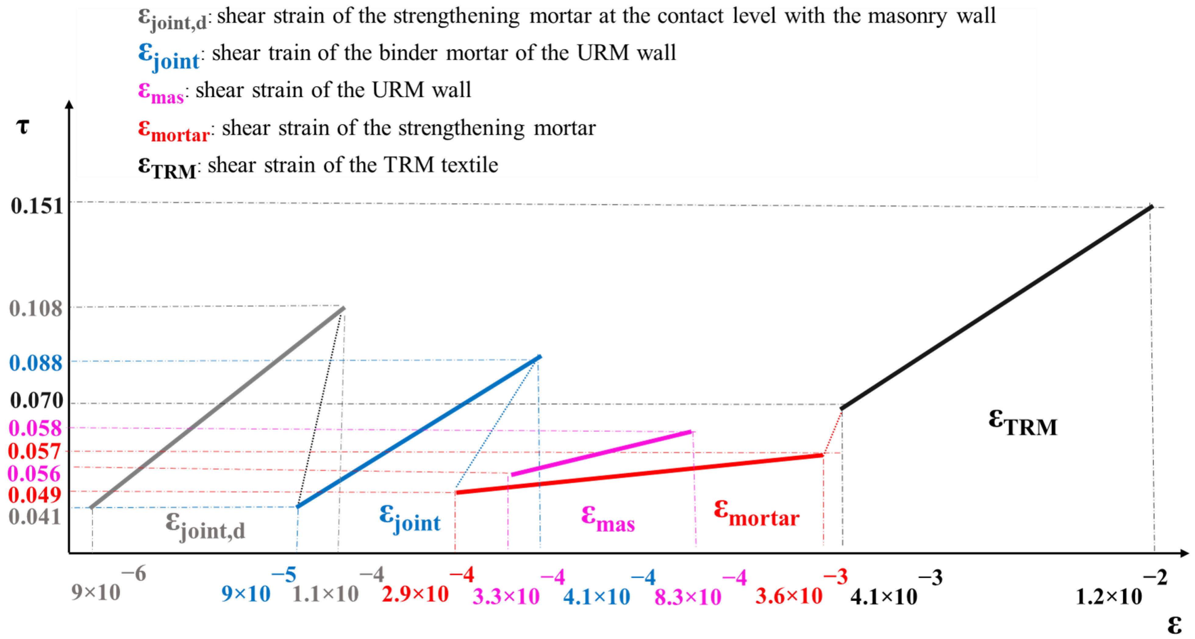
Figure 1. Experimental test setup of masonry walls under diagonal compression test (denoted as load P in the Figure) ASTM E519/2010 or in-plane shear test (denoted as loads N and V).
Fibers 11 00053 g001
Figure 2. (a) Compression stresses and shear stresses in terms of principal stresses (b) Three-linear stress–strain curve of TRM coupon tensile strength.
Fibers 11 00053 g002
Figure 3. Ranges of experimental shear stresses and strains of binder mortar, masonry wall, strengthening mortar, and TRM textile.
Fibers 11 00053 g003
Figure 4. Envelope of failure for URM walls and failure mode type [47,48,49].
Fibers 11 00053 g004
Figure 5. Algorithm for defining model accuracy in predicting the failure mode of URM walls retrofitted with a TRM jacket based on the shear strengths (VRd, Vm).
Fibers 11 00053 g005
Figure 6. Estimator charts for (a) the shear capacity predictions of non-strengthened and (b) strengthened URM with different TRM systems for design models and regulations.
Fibers 11 00053 g006
Figure 7. Accuracy of model predictions for strengthened URM: (a) with the different substrate material, (b) failure modes in masonry substrate, and (c) TRM strengthening system failure.
Fibers 11 00053 g007
Table 1. Ranges of experimental values of shear stresses and strains of binder mortars, masonry walls, strengthening mortars, and TRM textiles of the strengthened specimens.
τexpRange
(MPa)
εRange
(mm/mm)
Failure ModeType of TRM
Masonry substrateτεjoint0.041–0.088εjoint0.000095–0.000410SS-SFGTRM-CTRM
τεmas0.056–0.058εmas0.000330–0.000830DT-TCGTRM-CTRM
TRMτεjoint,d0.041–0.108εjoint,d0.000009–0.000110TRM FailureGTRM-CTRM
τεmortar0.049–0.057εmortar0.000288–0.003590TRM FailureGTRM-CTRM
τTRM0.070–0.151εTRM0.004100–0.011700TRM FailureCTRM-CTRM
Table 2. Values of calibration factor of the proposed model.
Types of Masonry UnitsTypes of Textile ReinforcementCoefficient
k
εtm
(%)
brickglass0.550.057
carbon0.600.112
cementglass0.520.038
carbon0.520.015
stoneglass0.590.038
Disclaimer/Publisher’s Note: The statements, opinions and data contained in all publications are solely those of the individual author(s) and contributor(s) and not of MDPI and/or the editor(s). MDPI and/or the editor(s) disclaim responsibility for any injury to people or property resulting from any ideas, methods, instructions or products referred to in the content.

