Article

Mechanical Properties of 3D-Printed Carbon Fiber-Reinforced Cement Mortar

1
Department of Civil Engineering, National Taipei University of Technology, Taipei 10608, Taiwan
2
Department of Civil and Environmental Engineering, Faculty of Science and Technology, University of Macau, Avenida da Universidade Taipa, Macau 999078, China
3
Umas Technology Co., Ltd., 9, Aly. 18, Ln. 671, Minsheng Rd., Wufeng Dist., Taichung City 41348, Taiwan
*
Author to whom correspondence should be addressed.
Fibers 2023, 11(12), 109; https://doi.org/10.3390/fib11120109
Submission received: 2 October 2023 / Revised: 24 November 2023 / Accepted: 30 November 2023 / Published: 11 December 2023

Abstract

:
The 3D printing process is different from traditional construction methods of formwork casting due to the use of additive manufacturing. This study develops a suitable 3D-printed carbon fiber-reinforced cement mortar (CFRCM) considering the extrudability, fluidity, setting time, and buildability of the CFRCM. The difference in compressive strength and flexural strength between 3D-printed specimens and conventional cast specimens was investigated by varying the amount of carbon fiber added (carbon fiber to cement ratio, 2.5 vol.‰, 5 vol.‰, 7.5 vol.‰, and 10 vol.‰) and the curing times (7th day and 28th day). The results of the experiments indicate that the addition of 6 wt.% cement accelerators to the cementitious mortar allows for a controlled initial setting time of approximately half an hour. The fluidity of the CFRCM was controlled by adjusting the dosage of the superplasticizer. When the slump was in the range of 150 mm to 190 mm, the carbon fiber to cement ratio 2.5 vol.‰ could be incorporated into the cementitious mortar, enabling the printing of hollow cylinders with a height of up to 750 mm. Comparing the 3D-printed specimens with the traditionally cast specimens, it was found that the addition of a carbon fiber to cement ratio of 7.5 vol.‰, and 10 vol.‰ resulted in the optimal compressive strength and flexural strength, respectively.

1. Introduction

The utilization of cementitious mortar in 3D printing has gained significant attention within the building and construction industry. This additive manufacturing technique enables the construction of three-dimensional objects through a meticulous layer-by-layer deposition process. Notably, 3D printing of cementitious mortar has proven instrumental in enhancing construction efficiency and reducing labor requirements when compared to traditional methods [1,2]. This technology is rapidly advancing and offering numerous advantages, for example, Menna et al. utilized the digital fabrication of concrete (DFC) to enable freedom of form to produce various concrete products with primarily architectural and aesthetic functions. It customizes the final shape while optimizing the structural/functional properties, material use, total cost, and architectural effect [3]. However, how to design successful 3D printing materials, processes, and structures is an important issue. The multi-level material design (MMD) for 3D printing was proposed by Lu et al., which indicated the mixture design, printing process, and composite structure [4].
Two primary 3D printing technologies have emerged as common practices: contour crafting [5,6,7] and robotic arm systems [8]. Large-scale automated extrusion 3D printing processes have been applied in construction and architecture, such as the individual components of a bridge [9,10]. Furthermore, ultra-high-performance concrete is systematically layered by an extrusion print head, affixed to a six-axis robotic arm. In one example of architectural use, a structural element was manufactured, culminating in complex 3D geometries [11]. To realize the successful 3D printing of cementitious mortar, a robust numerical model was developed to scrutinize the mechanical behavior of 3D-printed concrete after material deposition. Material testing demonstrated a linear increase in both Young’s modulus and cohesion correlating with the concrete’s age. This model was corroborated by printing experiments and was found to reliably forecast failure deformation patterns [12,13,14].
Reinforced concrete stands as the most widely employed housing structure due to its ability to enhance the ductility and load-bearing capacity of concrete through the incorporation of reinforcing steel. However, when it comes to the 3D printing concrete process, placing steel reinforcement poses a significant challenge. There are two methods to meet this challenge; the first focuses on incorporating continuous metal cables that are placed on the 3D-printed materials as reinforcement and tested for flexural resistance [15,16,17,18]. Another method focuses on incorporating fibers into 3D-printed materials, aiming to enhance the strength and toughness of 3D-printed structures [19,20,21,22]. Materials such as steel fibers have demonstrated the capability to improve the mechanical properties of concrete [23,24,25]. Alternatively, alkali-resistant and lightweight materials such as polypropylene fibers have been utilized [26,27]. Carbon fiber, known for its high specific strength, has also been employed to reinforce cement mortar, increasing tensile strength and impact resistance [28]. Additionally, polyvinyl alcohol (PVA) fibers and glass fibers have also been successfully utilized in this context [29,30].
The 3D printing process necessitates favorable properties for cementitious mortar. Perrot et al. integrated predictive analytics and numerical tools that can be used to model and understand the important mechanisms of extrusion-based 3D-printed cement mortars at different stages. These include mixing, material transfer, layer deposition, the mechanical behavior of freshly printed structures, and their early curing [31]. Among them, 3D printing cementitious mortar relies on four crucial components: extrudability, fluidity, open time (setting time), and buildability. To ensure extrudability, the material must be effortlessly transported to the nozzle for continuous extrusion and be devoid of clogging [32]. Chemical additives are frequently employed to enhance the rheological parameters of cementitious mortars and to attain the desired consistency and prolong fluidity. For instance, the use of a superplasticizer (SP), a polymeric dispersant, can improve the flow characteristics of concrete by reducing the attraction between cement particles, thereby minimizing yield stress and viscosity [33,34]. Viscosity modifier admixtures (VMAs) can enhance the stability and cohesion, and can impact the layer deformation of concrete [35]. Cement accelerators play a role in influencing the print path length, construction time, and environmental conditions. They facilitate early cementitious mortar strength development, consequently reducing the print interval for each layer in the printing process [36].
Regarding fluidity and dynamic yield stress, the plastic viscosity of cementitious mortar can be determined using a rheometer [37,38,39]. A flow test was used to assess the fluidity of cementitious mortar, and the test measured the 3D printing range of materials with slump values ranging from 4 mm to 8 mm and flow values from 170 mm to 226 mm. Although this measurement of slump and flow for fluidity tests is non-standardized, it provides an approach to enhance research reliability [40,41,42].
The strength evolution of the cementitious mortar occurs over time. The setting time of the material needs to be adjusted based on the size of the printed structure. The setting time can be determined through various standards. One approach involves allowing the material to rest for 30 min, followed by extrudability testing every 10 min until rupture occurs, with the recorded time considering the setting time [43]. The mixture’s initial and final setting time is measured using a viscometer and a needle penetrometer to meet the requirements of 3D printing [44,45]. The material must transition from low yield strength and low viscosity, suitable for pumpability, to high yield strength within a short period [46,47,48]. Achieving good buildability entails having high yield strength to minimize deformation and collapse caused by the layer-by-layer stacking load during printing. The material’s ability to resist its weight and the weight-induced deformation when printing successive layers, particularly in cementitious mortar, is crucial [49,50,51]. In addition, measuring layer height or the number of printable layers was used to predict the buildability of printing [52].
By printing specimens and testing them in different printing directions, the pressure exerted by the printing extrusion process compacts the material in the longitudinal direction [53,54]. One of the studies investigated the anisotropic behavior of 3D-printed ultra-high-performance fiber-reinforced concrete (UHPFRC). The compressive strength was found to be highest in the vertical plane, while the UHPFRC specimens exhibit the highest flexural strength in the horizontal plane. When the fiber volume fraction was 2%, the printed samples showed a 39% increase in fracture modulus compared to the cast specimens [55]. Furthermore, the addition of carbon fiber, glass fiber, and basalt fiber to cementitious mortar allows for the study of fiber arrangement and the control of the strength of the printed structure. The results show that the specimen with 1 vol.% carbon fiber content can obtain high compressive strength and flexural strength [56].
Existing research on the utilization of carbon fiber in 3D-printed cementitious mortar is limited, necessitating further comprehensive investigations. Nevertheless, carbon fiber exhibits notable attributes such as high specific strength, lightweight composition, and resistance to corrosion and fatigue. It finds widespread application in various fields, including sports equipment, offshore wind blades, and civil engineering. Researchers have demonstrated that incorporating carbon fibers into cementitious mortar results in exceptional mechanical properties, making it suitable for the repair of reinforced concrete structures [57].
This study aims to develop a mixed design for 3D-printed carbon fiber-reinforced cement mortar (CFRCM). Chopped carbon fibers with a length of 6 mm were employed, and different volumes of carbon fibers were added to the cementitious mortar. Cement accelerators are utilized to control the setting time of the cementitious mortar. To mitigate the risk of noticeable cracking and clogging during the printing process, a super-plasticizer was appropriately introduced to the cementitious mortar. The material will undergo tests to assess flow, setting time, and buildability. After confirming the extrudability, buildability, and flow behavior of 3D printable CFRCM, the CFRCM was successfully printed with hollow cylinder bodies with a height of 750 mm and 100 layers in 8 min (about 5 s per layer); this shows that the CFRCM in this study has superior buildability. Finally, this study focuses on the influence of varying amounts of chopped carbon fiber mixed with cementitious mortar on the compressive strength and flexural strength of 3D-printed specimens and compares them with traditionally casted specimens.

2. Experimental Program

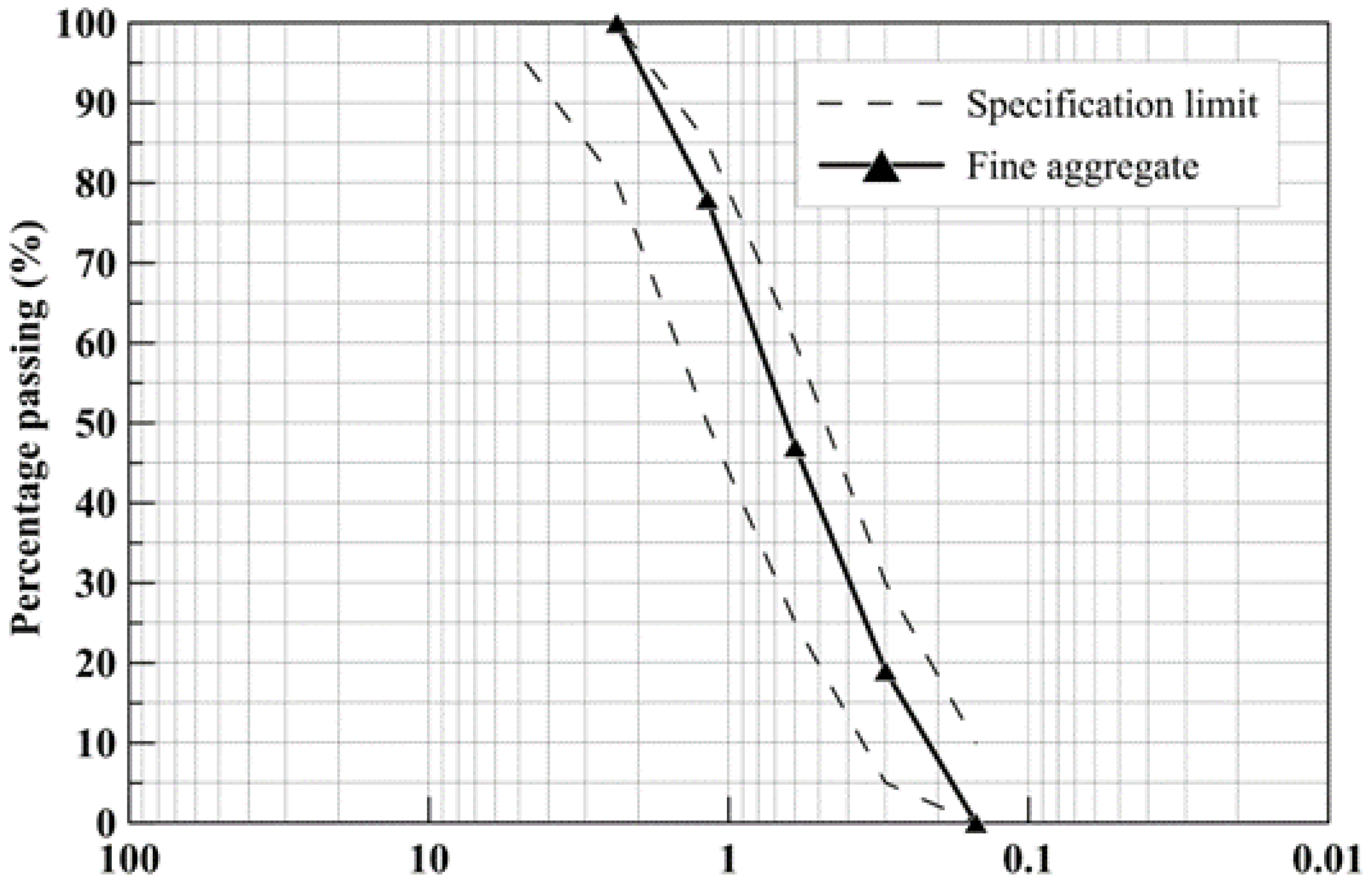
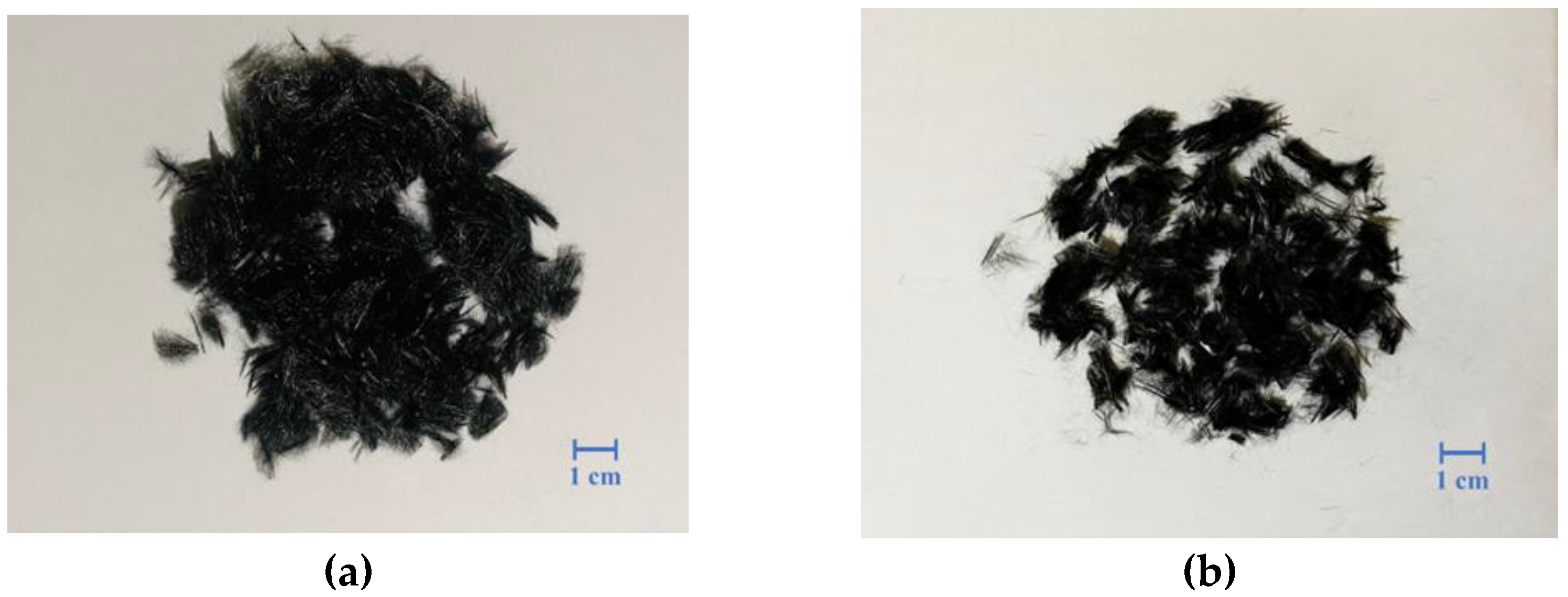
2.1. Materials and Mix Design

The mixed design of 3D-printed cement mortar should satisfy extrudability, flowability, setting time, and buildability specifications. The experimental materials used in this research are Type I Portland cement and sand with a maximum size that stops at #16 mesh (1.18 mm). According to ASTM C33/C33M-18 [58], the fineness modulus standard of the fine aggregate used was to be between 2.3 and 3.1. The fineness modulus (FM) was determined to be 2.57; Figure 1 illustrates the particle size distribution curves. Carbon fibers were chopped to a length of 6 mm, with a density of 1.78 g/cm3 and a tensile strength of 3500 to 6000 MPa. Table 1 presents the material properties of carbon fiber. These chopped carbon fibers were processed with heat treatment to remove the silane sizing on the fibers, and previous studies have indicated that the silane present in carbon fibers could be eliminated by heating them in the temperature range of 530–550 °C for 3 h, resulting in negligible residual silane [59]. Figure 2a shows the chopped carbon fiber after the heat treatment. Then, the chopped carbon fiber was placed in a closed container, and the high-pressure airflow was passed through the vent hole to make the chopped carbon fiber generate huge turbulence. Pneumatic dispersion can effectively separate the carbon fibers in the container, as shown in Figure 2b. A superplasticizer was used to facilitate effective cement dispersion, slump retention, and proper air entrainment, thereby providing desirable fluidity and facilitating concrete pumping. In addition, the setting time and hardening properties of the cement mortar are modulated by an accelerator to accelerate the hydration of the cement to achieve the desired buildability during the 3D printing of the cement mortar. A non-toxic alkali-free cement accelerator that does not cause additional environmental pollution was chosen for this experiment.
The CFRCM for 3D printing was designed as follows. Different amounts of chopped carbon fiber to cement volume ratios (2.5‰, 5‰, 7.5‰, and 10‰) were added to the cementitious mortar. The water–cement ratio was kept at 0.4, and the cement–sand ratio was 1:1.05. To maintain the same setting time of the CFRCM in 3D printing, a 6 wt.% cement accelerator was added. The amount of superplasticizer to cement weight ratio was adjusted to achieve a fluid consistency during the 3D printing process, ranging from 0.6 wt.% to 2.5 wt.% in the CFRCM. The composition ratios of the CFRCM are listed in Table 2.

2.2. Experimental Procedures

The performance of cementitious mortar can be evaluated based on the following properties. First, the extrudability of cementitious mortar was tested by continuously extruding four slender cementitious mortars using a peristaltic pump. The purpose was to determine the optimal aggregate weight ratio. Next, the buildability of the CFRCM was assessed by printing a continuous hollow cylinder with a diameter of 100 mm and a height of 200 mm using a 3D printing machine system. The fluidity and setting time of the cementitious mortar were measured during the printing process. Finally, both the 3D-printed specimens and the traditionally cast specimens were subjected to compressive and flexural strength testing.

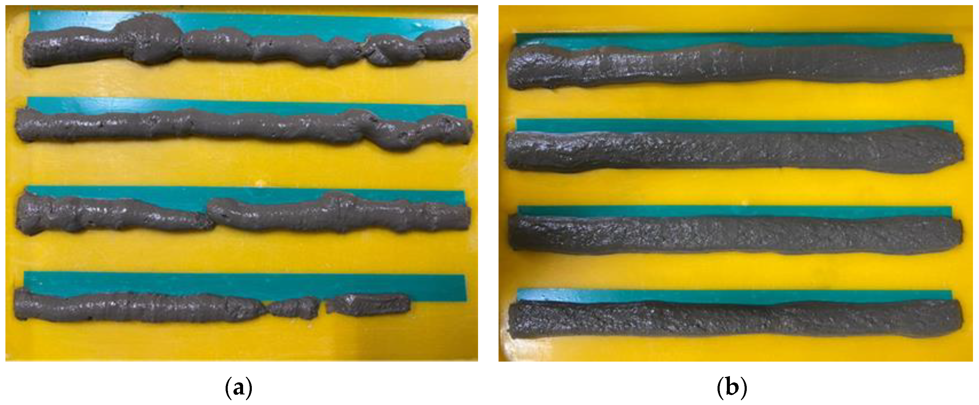
2.2.1. Extrudability

For this study, a peristaltic pump (WS-300, Tohama Co., Ltd., New Taipei City, Taiwan) was used to squeeze out the cementitious mortar to perform the extrudability test. The set speed was 40 rpm and the nozzle diameter was 12.7 mm. The extrudability was defined as the ability of the cementitious mortar to pass through the soft pipes and nozzles of a peristaltic pump, based on the method proposed by Le et al. [32]. Continuously extruded cement mortar in the form of four parallel lines (300 mm each) was used as the extrudability test metrics in this study, as shown in Figure 3. The test results were categorized as “Pass” or “Fail” based on whether the cementitious mortar was successfully deposited over its entire length without clogging or cracking.

2.2.2. Fluidity

The fluidity test ensures the smooth transfer of the CFRCM from the storage hopper to the nozzle. The fluidity of the CFRCM over time was evaluated according to ASTM C230/C230M-20 [60]. The flow table test involved dropping the cementitious mortar 25 times within 15 s, with each drop height being 12.7 mm. The diameter of the cementitious mortar after 25 dropping occasions was measured four times at 45° intervals and the average value was calculated.

2.2.3. Initial Setting Time
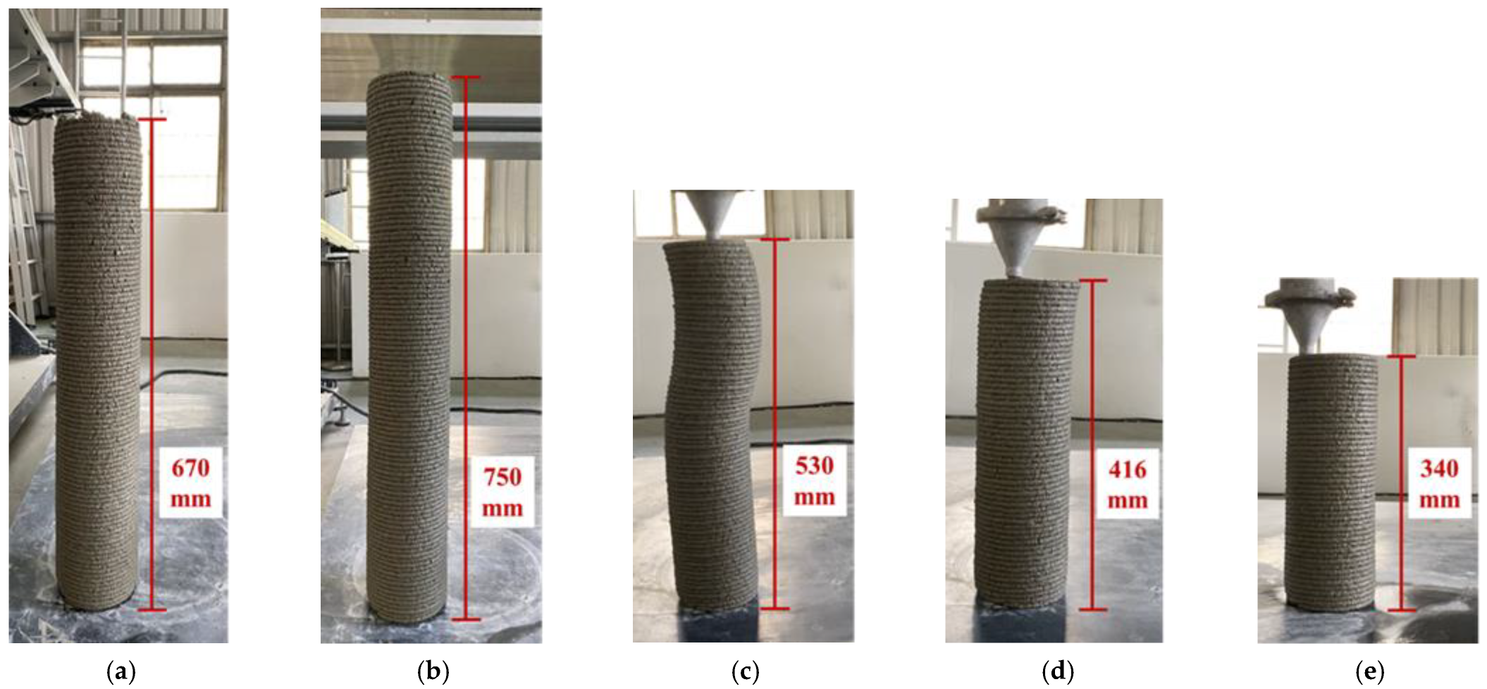
The initial setting time of the cement material was determined through Frick’s needle test to understand the buildability of the cement after printing. The cement accelerator was incorporated into the cement mortar following the mixing method specified in ASTM C187-16 [61], and the setting time was determined using Fricker’s needle method described in ASTM C191-21 [62]. The initial setting time was measured as the time from the initial contact between the cement and mixing water until the measured penetration reached 25 mm.

2.2.4. Buildability

A contour crafting 3D printer (UMAS Technology Co., Ltd., Taichung, Taiwan) was used to print the CFRCM specimens. The contour crafting 3D printer had dimensions of 2 m × 2 m × 2 m, as shown in Figure 4. The diameter of the nozzle was 15 mm, and the printing speed was set at 45 mm/s ± 5 mm/s.
The study focused on scrutinizing the extrudability and constructability of cementitious mortar enriched with chopped carbon fiber, while also understanding its flow behavior. Researchers often use continuous printing of hollow cylinders to test constructability, which is a well-received technique [63,64,65]. In this study, the specific procedure to evaluate constructability involved 3D-printing a hollow cylinder composed in an uninterrupted, continuous fashion using a predefined number of layers. The degree of deformation in the printed element was then evaluated, and the limiting height of the hollow cylinder was tested. The process concluded with the measurement and recording of the number of layers that had collapsed.

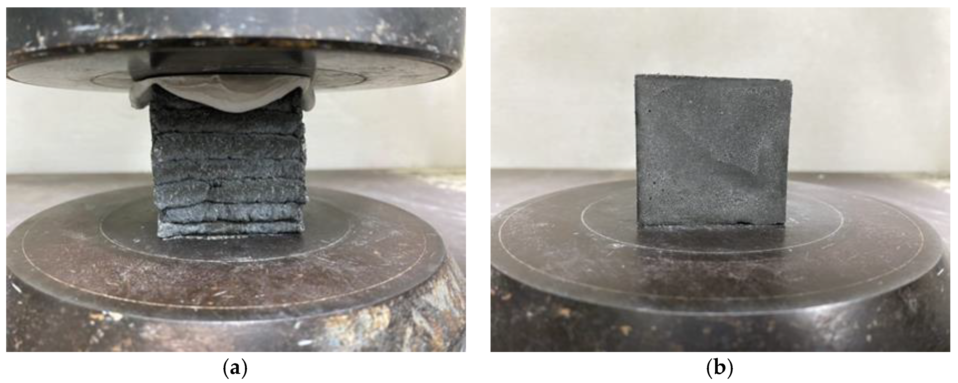
2.2.5. Compression Test

After mixing, 3D-printed specimens and molded specimens were prepared. The compression test method was based on ASTM C109/C109M-20 [66]. The size of the compression specimen was 50 mm × 50 mm × 50 mm. Figure 5a,b show the experimental procedure for the 3D printed specimen and cast specimen compression tests, respectively. The specimens were cured in a water tank and tested at 7th and 28th days of age to determine the change in strength over time. Each test group had three specimens.

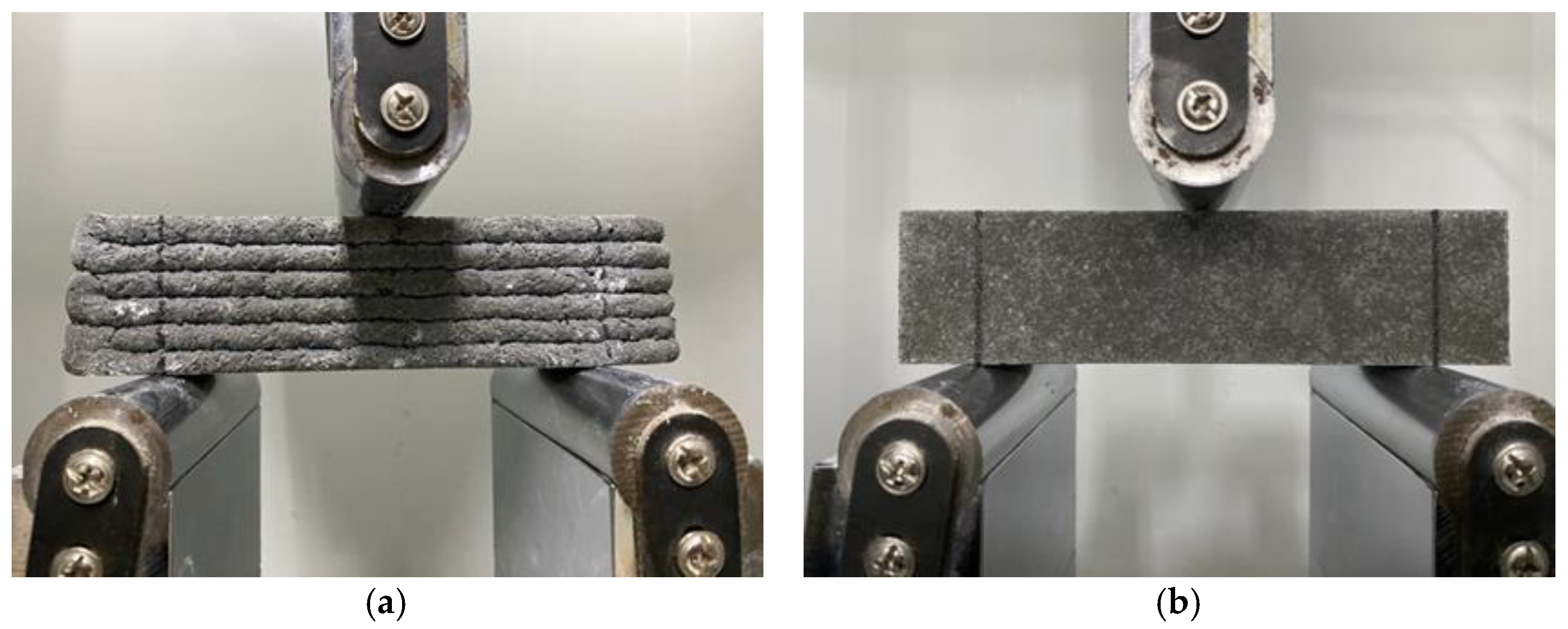
2.2.6. Flexural Test

The flexural test method was based on ASTM C293/C293M-16 [67]. The size of the bending specimen was 40 mm × 40 mm × 160 mm. Each test group had three specimens. Figure 6a,b show the experimental procedure for the 3D-printed and cast specimen flexural tests, respectively. The specimens were maintained in a water tank and tested at 7th and 28th days of age to test the change in strength over time. Since the 3D-printed flexural specimens were printed layer by layer, the printed sizes were different, the cross-sectional area of each bending specimen was measured, and the moment of inertia of the cross-section was calculated. The flexural strength ( σ F ) in MPa was calculated using Equation (1):
σ F = M × y I
where σ F represents the flexural strength, M is the maximum flexural moment, y is the distance between the neutral axis and the bottom edge, and I is the moment of inertia (mm4).
The formula for the maximum flexural moment was calculated using Equation (2):
M = P × L 4
where P is the maximum applied load recorded by the test machine in Newton (N), L denotes the span length in millimeters (mm).

3. Results and Discussion

3.1. Extrudability

Manual testing using a peristaltic pump was conducted to assess the extrudability of sand particles. Considering a nozzle diameter of 12.7 mm, sand particles with a maximum diameter of less than 2 mm were utilized. The sand composition for this study consisted of four sizes: #16 (1.18 mm), #30 (0.60 mm), #50 (0.30 mm), and #100 (0.15 mm). The weight ratios of the sand particles were maintained as follows: #16:#30:#50:#100 = 1.6:1.7:1.5:1. The fixed water–cement ratio was set at 0.4, while the weight ratio of sand particles passing through the maximum sieve (#16) was adjusted to 1.6, 1.2, 1.0, and 0. The particle size of the sand significantly impacts the overall fluidity of the cementitious mortar. The following nomenclature is used to describe the extrudability analysis, where “S” represents the weight ratio of sand particles on #16.
Figure 7 presents the results obtained for the four weight ratios of sand particles passing through sieve #16. In the sieve #16 ratio of 1.6, the cementitious mortar experienced a blockage in the peristaltic pump due to poor fluidity with high sand content, as depicted in Figure 7a. On the other hand, in the sieve #16 ratio of 1.2, the cementitious mortar could be consistently extruded from the nozzle, forming continuous strips of 300 mm in length, without any blockage or cracking, as shown in Figure 7b. However, at the #16 sieve ratio of 1.0 and 0, the cementitious mortar exhibited increased viscosity, resulting in a blockage at the rear of the system, as illustrated in Figure 7c and 7d, respectively. Therefore, the weight ratio of #16:#30:#50:#100 = 1.2:1.7:1.5:1 was used for the sand aggregates in this study.

3.2. Assessment of Fluidity

The fluidity test was designed to ensure that the cementitious mortar could be smoothly conveyed from the hopper to the nozzle. Each test group had four specimens. With the temperature change, the fluidity of the CFRCM was greatly affected. The lower the temperature (20 ± 5 °C), the slower the setting time of the cementitious mortar, and the more cement accelerator was required. Therefore, the buildability of cementitious mortar was tested with the addition of up to 6 wt.% of the cement accelerator. The test results showed that by adding 6 wt.% cement accelerators to the cementitious mortar, the setting time of the 3D-printed cementitious mortar was shortened. The fluidity needed to be tested by increasing the fluidity of the CFRCM using a superplasticizer. After controlling the amount of cement accelerator added, the amount of superplasticizer added was adjusted. However, the fluidity of the 3D-printed specimens ranged from 174.59 ± 3.34 mm to 188.21 ± 2.08 mm, as shown in Table 3. With the temperature increasing, to maintain the fluidity of the CFRCM, more superplasticizers were required with a fixed amount of cement accelerator. Table 4 shows the flow range of printable hollow cylinder heights from 156.45 ± 2.52 mm to 176.63 ± 2.02 mm. The test results show that the flow values of 3D-printed cement mortar in this study are from 155 mm to 190 mm.

3.3. Initial Setting Time

The impact of the cement accelerator on the fluidity of the cementitious mortar over a given duration was scrutinized. To expedite the setting time of the CFRCM for the construction of hollow cylindrical specimens, the accelerator-to-cement ratio was escalated to 6 wt.%. This resulted in a drastic reduction in the initial setting time to a mere 30 min.

3.4. Buildability

This subsection explains how the fluidity of the CFRCM was maintained by adding superplasticizers to test the buildability of 25-layer CFRCM hollow cylinders with varying additions of chopped carbon fiber (2.5 vol.‰, 5 vol.‰, 7.5 vol.‰, and 10 vol.‰) at a fixed cement accelerator dosage of 6 wt.%. The printing speed ranged from 45 ± 5 mm/s per layer. Table 5 lists the heights of hollow cylinders built using CFRCM with different carbon fiber additions. Figure 8 showcases the effect of different carbon fiber additions in meeting buildability requirements through the construction of hollow cylinders. In Figure 8a, the foundation specimen without fiber (SP1.6-A6B) achieved a buildable height of 670 mm, while Figure 8b demonstrates a buildable height of 750 mm using 2.5 vol.‰ of CFRCM (SP1.7-A6CF2.5). Both cases exhibited no noticeable deformation. However, Figure 8c shows a reduced buildable height of 530 mm when using 5 vol.‰ of CFRCM (SP1.9-A6CF5), with significant collapse observed. In contrast, Figure 8d,e reveal buildable heights of 416 mm and 340 mm, respectively, for CFRCM additions of 7.5 vol.‰ (SP1.9-A6CF7.5) and 1.0 vol.‰ (SP2.3-A6CF10), but both experienced collapses.

3.5. Compression Test Result

This section focuses on the compression test results obtained from both the 3D-printed and cast specimens, with benchmark (without carbon fiber) and with fiber addition ratios of 2.5 vol.‰, 5 vol.‰, 7.5 vol.‰, and 10 vol.‰. The 7th day and 28th day average compressive strength values for the benchmark and the specimens incorporating various proportions of CFRCM are presented in Table 6. The specimen nomenclature followed this convention: C denotes the compression test, B represents the benchmark, CF refers to the carbon fiber at 2.5 vol.‰, 5 vol.‰, 7.5 vol.‰, and 10 vol.‰, and 3DP indicates 3D printing.
The results demonstrate that the 7th day compressive strength enhancements observed in the 3D-printed specimens exhibited improvements of 3%, −4%, 7%, and 3% compared to the benchmark. Similarly, the 7th day cast specimens displayed strength increments of 2%, 2%, 5%, and 0% compared to the benchmark. However, the 28th day compressive strengths of both 3D-printed and cast specimens represent the benchmark and varying addition ratios of CFRCM. Comparative analysis revealed that the 3D-printed specimens exhibited strength improvements of 4%, −8%, 15%, and 7% compared to the benchmark. Similarly, the cast specimens displayed strength enhancements of 7%, 6%, 19%, and 11%.
Evaluation of the compressive test results indicated that both the 3D-printed and cast specimens with a carbon fiber addition of 5 vol.‰ might not adequately support the strength of the cementitious mortar, resulting in a decrease in compressive strength. However, specimens with a carbon fiber addition of 7.5 vol.‰ exhibited the highest compressive strength. Notably, the 3D-printed and cast specimens with a carbon fiber addition of 10 vol.‰ displayed increased porosity, leading to a reduction in compressive strength.
The average compressive strength results for CFRCM, fabricated through both 3D printing and casting techniques, are presented in Figure 9. Various fiber volume additions were evaluated in this study. Notably, the specimens containing 7.5 vol.‰ of CFRCM demonstrated the highest compressive strengths, irrespective of the fabrication method employed.
Comparing the two fabrication methods, the 3D-printed specimens exhibited slightly higher average compressive strengths than the cast specimens. This can be attributed to the mechanical pressure applied during the extrusion process, which enhanced the material’s densification. The test results indicated that the 7th day compressive strengths of both the 3D-printed and cast specimens, incorporating fiber volume additions ranging from 2.5 vol.‰ to 10 vol.‰, were within the range of 49.82 MPa to 58.48 MPa. However, from the 28th day average compressive strength outcomes for 3D-printed and cast CFRCM with varying fiber volume additions, a consistent trend could be observed in the 28th day average compressive strength results: the 3D-printed specimens developed higher compressive strength than the traditional cast specimens. Based on the test results, both the 3D-printed and cast specimens exhibited average compressive strengths ranging from 57.86 MPa to 76.46 MPa, representing an increase compared to the 7th day average compressive strength.

3.6. Flexural Test Result

The flexural strengths of both printed and cast specimens were examined at fiber addition ratios of 2.5 vol.‰, 5 vol.‰, 7.5 vol.‰, and 10 vol.‰. Table 7 presents the 7th day and 28th day average flexural strengths of the 3D-printed and cast specimens for the benchmark and CFRCM specimens with various addition ratios. The specimen nomenclature is as follows: F denotes the flexural test, B represents the benchmark, CF indicates the carbon fiber (2.5 vol.‰, 5 vol.‰, 7.5 vol.‰, 10 vol.‰), and 3DP refers to 3D printing.
To ensure greater accuracy, the moment of inertia of the fracture surface of the printed specimen was calculated and incorporated into the flexural strength formula. The 3D-printed specimens exhibited improvements in flexural strength by 15%, 17%, 31%, and 37% compared to the benchmark. Similarly, the cast specimens displayed strength enhancements of 1%, 14%, 26%, and 30% compared to the benchmark. As for the 28th day test results, the 3D-printed specimens showed improvements in flexural strength by 17%, 23%, 24%, and 36% compared to the benchmark, while the cast specimens exhibited flexural strength enhancements of 6%, 10%, 10%, and 15% compared to the benchmark.
The flexural test results indicated that both the 3D-printed and cast specimens with a 10 vol.‰ of CFRCM displayed higher average flexural strength than the benchmark (36% and 15%, respectively). Moreover, the flexural strength of the CFRCM increased with the amount of added fiber. The flexural strength of the 3D-printed CFRCM exhibited a greater increase compared to the benchmark.
Figure 10 illustrates the 7th day and 28th day average flexural strength results for 3D-printed and cast CFRCM with varying fiber volume additions. Both 3D-printed and cast specimens with a 10 vol.‰ CFRCM exhibited the highest flexural strength. The flexural strength increased with the amount of added carbon fiber. According to the test results, the 7th day flexural strength of the 3D-printed specimens was slightly higher than that of the cast specimens. The average flexural strength of both the 3D-printed and cast specimens ranged from 6.37 MPa to 10.05 MPa. Similar to the 7th day results, the average flexural strengths of the 28th day specimens increased as the amount of carbon fiber added increased. The 28th day flexural strengths of both the 3D-printed and cast specimens ranged from 7.73 MPa to 10.56 MPa.
Optical microscope images of the 3D-printed flexural specimens in a damage mode are depicted in Figure 11a–c. Upon examination under the magnification of the optical microscope, it could be observed that numerous chopped carbon fibers continue to stretch. The confined diameter of the nozzle forced the chopped carbon fibers to align parallel with the printing direction during the 3D printing process of the CFRCM. This alignment provided a mechanism for the carbon fibers to restrain crack propagation, thereby enhancing the flexural strength of the resulting product. Furthermore, the mechanical pressure exerted during the 3D printing process imparts slightly superior flexural strength to the printed specimens, as compared to their cast counterparts. This observation underscores the advantage of 3D printing techniques in producing more resilient CFRCM structures.

4. Conclusions

The extrudability, buildability, fluidity, and mechanical properties of CFRCM fabricated using 3D printing were investigated and tested in this study. The research focused on examining the effects of different carbon fiber additions, comparing the mechanical properties between 3D printing and casting techniques. Based on the above test results, the following conclusions are drawn:
  • The CFRCM was successfully printed under a printable flow area ranging from 155 mm to 190 mm. Furthermore, the test results demonstrated that the initial setting time was 30 min by adding 6 wt.% cement accelerators, and it enabled the construction of a 25-layer hollow cylinder.
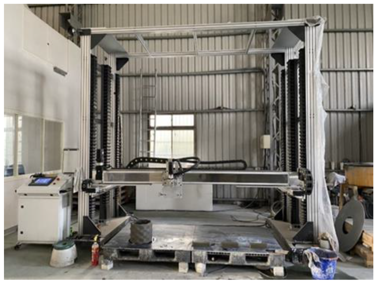
  • After confirming the extrudability, buildability, and flow behavior of 3D-printed CFRCM, the addition ratio of 2.5 vol.‰ carbon fiber of CFRCM helped to successfully print hollow cylinder bodies with a height of 750 mm (approximately 100 layers).
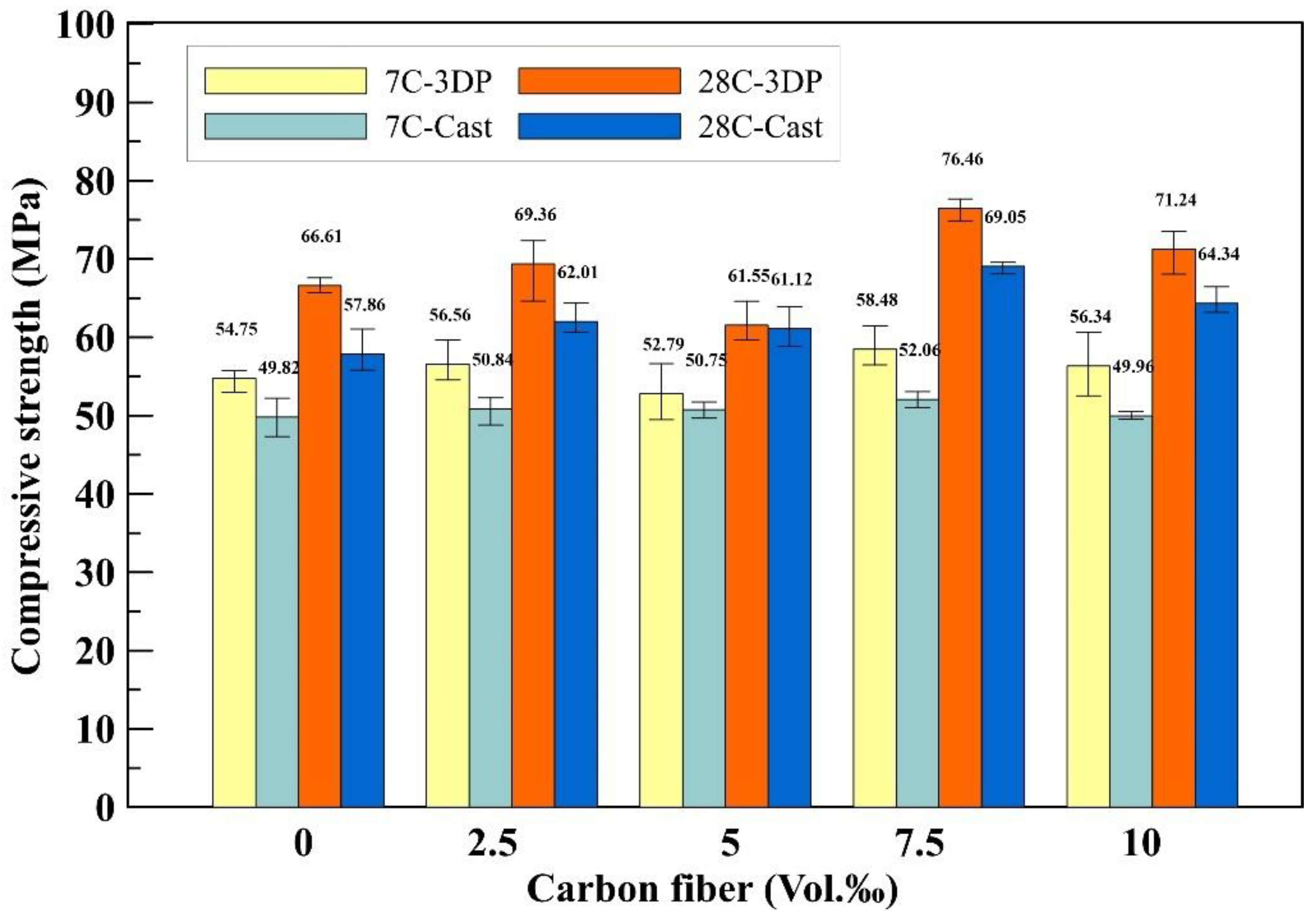
  • The compressive testing results revealed that both 3D-printed and cast specimens exhibited the highest compressive strength of CFRCM when using 7.5 vol.‰ chopped carbon fiber, resulting in strength improvements of 15% and 19%, respectively. The compressive strengths of the 3D-printed and cast specimens ranged from 57.86 MPa to 76.46 MPa.
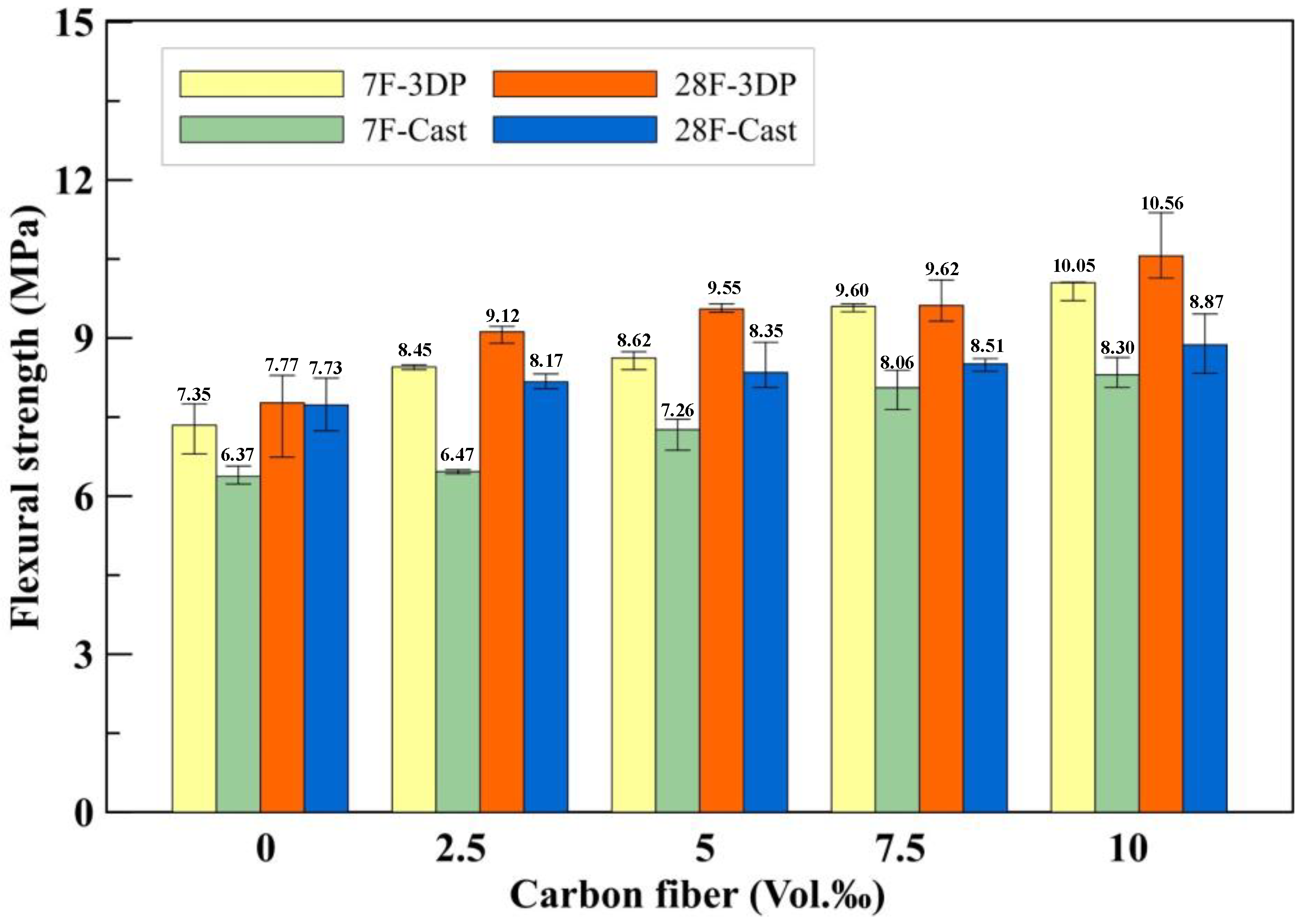
  • The flexural test results demonstrated that the highest flexural strength of CFRCM was achieved in both 3D-printed and cast specimens when using 10 vol.‰ chopped carbon fiber, leading to strength enhancements of 26% and 15%, respectively. The flexural strengths of the 3D-printed and cast specimens ranged from 7.73 MPa to 10.56 MPa.
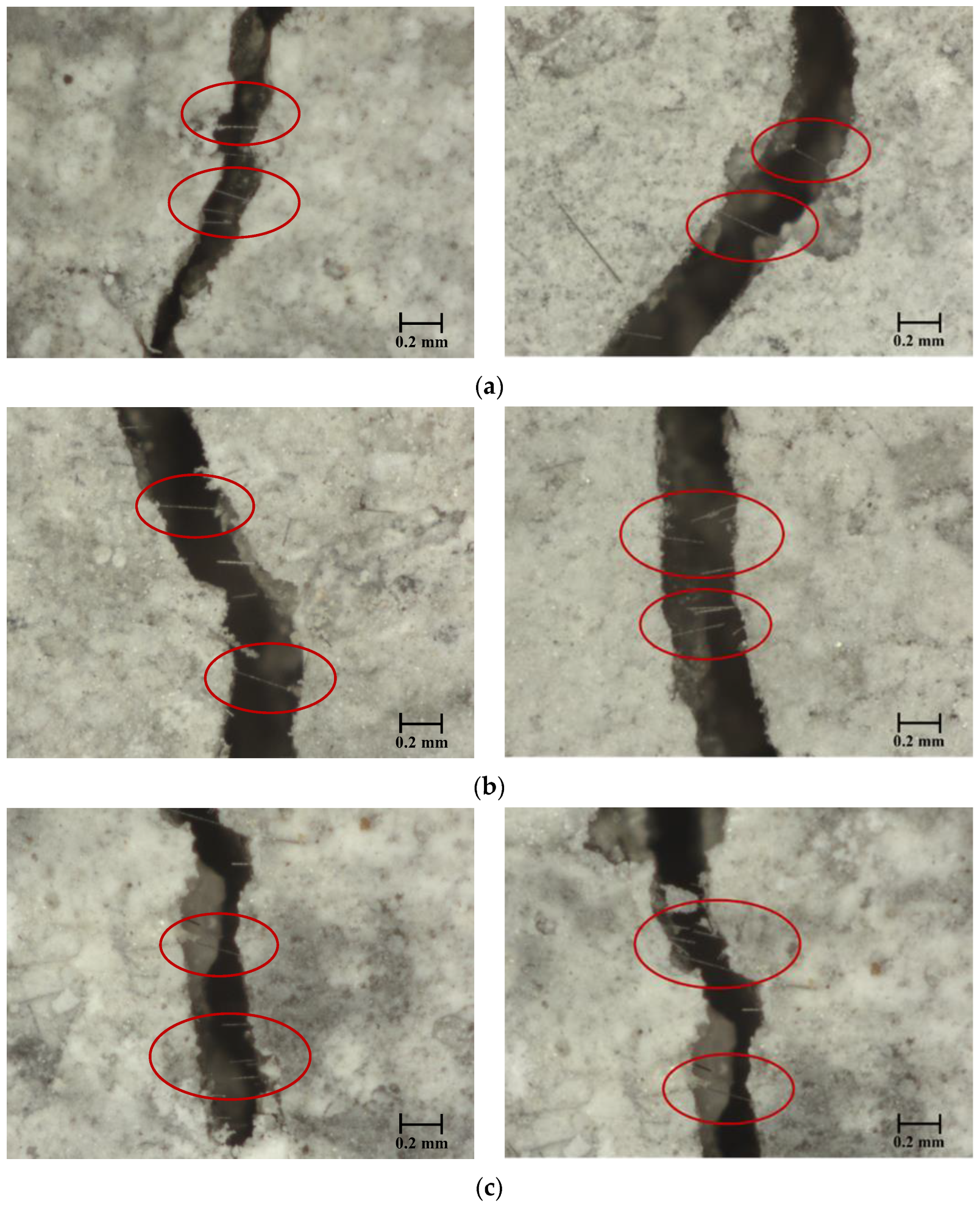
  • During CFRCM 3D printing, the small nozzle diameter aligns chopped carbon fibers parallel to the print direction, mitigating crack propagation and boosting flexural strength. Consequently, the 3D-printed specimens demonstrate superior strength to cast ones.
  • According to the test results, 3D-printed CFRCM improves mechanical strength and toughness.

Author Contributions

Conceptualization, Y.-F.L.; data curation, P.-J.T. and J.-Y.S.; formal analysis, P.-J.T. and J.-Y.S.; investigation, P.-J.T. and H.-S.C.; methodology, Y.-F.L. and M.-H.L.; project administration, Y.-F.L.; supervision, Y.-F.L.; writing—original draft, P.-J.T. and J.-Y.S.; Writing—review and editing, Y.-F.L. and M.-H.L. All authors have read and agreed to the published version of the manuscript.

Funding

This research was funded by the Ministry of Science and Technology, Taiwan, under contract No. NSTC 111-2221-E-027-023; the Ministry of Education in Taiwan under contract No. L7111101-7; and the “Research Center of Energy Conservation for New Generation of Residential, Commercial, and Industrial Sectors” from the Ministry of Education in Taiwan under contract No. L7101101-19.

Institutional Review Board Statement

Not applicable.

Informed Consent Statement

Not applicable.

Data Availability Statement

Data are contained within the article.

Conflicts of Interest

Author Huei-Shiung Chen was employed by the company Umas Technology Co., Ltd. The remaining authors declare that the research was conducted in the absence of any commercial or financial relationships that could be construed as a potential conflict of interest.

References

  1. Khoshnevis, B.; Dutton, R. Innovative rapid prototyping process makes large sized, smooth surfaced complex shapes in a wide variety of materials. Mater. Technol. 1998, 13, 53–56. [Google Scholar] [CrossRef]
  2. Buswell, R.A.; De Silva, W.R.L.; Jones, S.Z.; Dirrenberger, J. 3D printing using concrete extrusion: A roadmap for research. Cem. Concr. Res. 2018, 112, 37–49. [Google Scholar] [CrossRef]
  3. Menna, C.; Mata-Falcón, J.; Bos, F.P.; Vantyghem, G.; Ferrara, L.; Asprone, D.; Salet, T.; Kaufmann, W. Opportunities and challenges for structural engineering of digitally fabricated concrete. Cem. Concr. Res. 2020, 133, 106079. [Google Scholar] [CrossRef]
  4. Lu, B.; Weng, Y.; Li, M.; Qian, Y.; Leong, K.F.; Tan, M.J.; Qian, S. A systematical review of 3D printable cementitious materials. Constr. Build. Mater. 2019, 207, 477–490. [Google Scholar] [CrossRef]
  5. Khoshnevis, B. Automated construction by contour crafting—Related robotics and information technologies. Autom. Constr. 2004, 13, 5–19. [Google Scholar] [CrossRef]
  6. Hwang, D.; Khoshnevis, B.; Daniel, E. Concrete wall fabrication by contour crafting. In Proceedings of the 21st International Symposium on Automation and Robotics in Construction (ISARC 2004), Jeju, Republic of Korea, 21–25 September 2004; pp. 301–307. [Google Scholar]
  7. Kazemian, A.; Yuan, X.; Cochran, E.; Khoshnevis, B. Cementitious materials for construction-scale 3D printing: Laboratory testing of fresh printing mixture. Constr. Build. Mater. 2017, 145, 639–647. [Google Scholar] [CrossRef]
  8. Zhang, X.; Li, M.; Lim, J.H.; Weng, Y.; Tay, Y.W.D.; Pham, H.; Pham, Q.-C. Large-scale 3D printing by a team of mobile robots. Autom. Constr. 2018, 95, 98–106. [Google Scholar] [CrossRef]
  9. Lim, S.; Buswell, R.; Le, T.; Austin, S.; Gibb, A.; Thorpe, T. Developments in construction-scale additive manufacturing processes. Autom. Constr. 2012, 21, 262–268. [Google Scholar] [CrossRef]
  10. Salet, T.A.M.; Ahmed, Z.Y.; Bos, F.P.; Laagland, H.L.M. Design of a 3D printed concrete bridge by testing. Virtual Phys. Prototyp. 2018, 13, 222–236. [Google Scholar] [CrossRef]
  11. Gosselin, C.; Duballet, R.; Roux, P.; Gaudillière, N.; Dirrenberger, J.; Morel, P. Large-scale 3D printing of ultra-high performance concrete—A new processing route for architects and builders. Mater. Des. 2016, 100, 102–109. [Google Scholar] [CrossRef]
  12. Wolfs, R.J.M.; Bos, F.P.; Salet, T.A.M. Early age mechanical behaviour of 3D printed concrete: Numerical modelling and experimental testing. Cem. Concr. Res. 2018, 106, 103–116. [Google Scholar] [CrossRef]
  13. Suiker, A. Mechanical performance of wall structures in 3D printing processes: Theory, design tools and experiments. Int. J. Mech. Sci. 2018, 137, 145–170. [Google Scholar] [CrossRef]
  14. Ooms, T.; Vantyghem, G.; Van Coile, R.; De Corte, W. A parametric modelling strategy for the numerical simulation of 3D concrete printing with complex geometries. Addit. Manuf. 2020, 38, 101743. [Google Scholar] [CrossRef]
  15. Bos, F.P.; Ahmed, Z.Y.; Jutinov, E.R.; Salet, T.A. Experimental exploration of metal cable as reinforcement in 3D printed concrete. Materials 2017, 10, 1314. [Google Scholar] [CrossRef] [PubMed]
  16. Lim, J.H.; Panda, B.; Pham, Q.-C. Improving flexural characteristics of 3D printed geopolymer composites with in-process steel cable reinforcement. Constr. Build. Mater. 2018, 178, 32–41. [Google Scholar] [CrossRef]
  17. Asakawa, T.; Nishiwaki, T.; Ohno, K.; Yokoyama, S.; Okada, Y.; Kojima, S.; Satake, Y.; Miyata, Y.; Miyazawa, Y.; Ito, Y.; et al. Fundamental Study on Automated Interlayer Reinforcing System with Metal Fiber Insertion for 3D Concrete Printer. In RILEM International Conference on Concrete and Digital Fabrication; Springer International Publishing: Cham, Switzerland, 2022; pp. 411–416. [Google Scholar]
  18. Cao, X.; Yu, S.; Zheng, D.; Cui, H. Nail planting to enhance the interface bonding strength in 3D printed concrete. Autom. Constr. 2022, 141, 104392. [Google Scholar] [CrossRef]
  19. Giwa, I.; Game, D.; Ahmed, H.; Noorvand, H.; Arce, G.; Hassan, M.; Kazemian, A. Performance and macrostructural characterization of 3D printed steel fiber reinforced cementitious materials. Constr. Build. Mater. 2023, 369, 130593. [Google Scholar] [CrossRef]
  20. Le, T.T.; Austin, S.A.; Lim, S.; Buswell, R.A.; Law, R.; Gibb, A.G.F.; Thorpe, T. Hardened properties of high-performance printing concrete. Cem. Concr. Res. 2012, 42, 558–666. [Google Scholar] [CrossRef]
  21. Luo, M.; Tian, X.; Shang, J.; Zhu, W.; Li, D.; Qin, Y. Impregnation and interlayer bonding behaviours of 3D-printed continuous carbon-fiber-reinforced poly-ether-ether-ketone composites. Compos. Part A Appl. Sci. Manuf. 2019, 121, 130–138. [Google Scholar] [CrossRef]
  22. Panda, B.; Paul, S.C.; Tan, M.J. Anisotropic mechanical performance of 3D printed fiber reinforced sustainable construction material. Mater. Lett. 2017, 209, 146–149. [Google Scholar] [CrossRef]
  23. Singh, A.; Liu, Q.; Xiao, J.; Lyu, Q. Mechanical and macrostructural properties of 3D printed concrete dosed with steel fibers under different loading direction. Constr. Build. Mater. 2022, 323, 126616. [Google Scholar] [CrossRef]
  24. Zhang, Y.; Zhang, Y.; Qian, R.; Liu, G.; Du, H. Influence of steel fiber on the water absorption of 3D printed concrete. Mater. Lett. 2023, 330, 133252. [Google Scholar] [CrossRef]
  25. Nair, S.A.; Tripathi, A.; Neithalath, N. Examining layer height effects on the flexural and fracture response of plain and fiber-reinforced 3D-printed beams. Cem. Concr. Compos. 2021, 124, 104254. [Google Scholar] [CrossRef]
  26. Ding, T.; Xiao, J.; Zou, S.; Yu, J. Flexural properties of 3D printed fibre-reinforced concrete with recycled sand. Constr. Build. Mater. 2021, 288, 123077. [Google Scholar] [CrossRef]
  27. Ma, L.; Zhang, Q.; Lombois-Burger, H.; Jia, Z.; Zhang, Z.; Niu, G.; Zhang, Y. Pore structure, internal relative humidity, and fiber orientation of 3D printed concrete with polypropylene fiber and their relation with shrinkage. J. Build. Eng. 2022, 61, 105250. [Google Scholar] [CrossRef]
  28. Ma, S.; Yang, H.; Zhao, S.; He, P.; Zhang, Z.; Duan, X.; Yang, Z.; Jia, D.; Zhou, Y. 3D-printing of architectured short carbon fiber-geopolymer composite. Compos. Part B Eng. 2021, 226, 109348. [Google Scholar] [CrossRef]
  29. Sun, X.; Zhou, J.; Wang, Q.; Shi, J.; Wang, H. PVA fibre reinforced high-strength cementitious composite for 3D printing: Mechanical properties and durability. Addit. Manuf. 2022, 49, 102500. [Google Scholar] [CrossRef]
  30. Liu, X.; Li, Q.; Li, J. Shrinkage and mechanical properties optimization of spray-based 3D printed concrete by PVA fiber. Mater. Lett. 2022, 319, 132253. [Google Scholar] [CrossRef]
  31. Perrot, A.; Pierre, A.; Nerella, V.; Wolfs, R.; Keita, E.; Nair, S.; Neithalath, N.; Roussel, N.; Mechtcherine, V. From analytical methods to numerical simulations: A process engineering toolbox for 3D concrete printing. Cem. Concr. Compos. 2021, 122, 104164. [Google Scholar] [CrossRef]
  32. Le, T.T.; Austin, S.A.; Lim, S.; Buswell, R.A.; Gibb, A.G.F.; Thorpe, T. Mix design and fresh properties for high-performance printing concrete. Mater. Struct. 2012, 45, 1221–1232. [Google Scholar] [CrossRef]
  33. Souza, M.T.; Ferreira, I.M.; de Moraes, E.G.; Senff, L.; de Oliveira, A.P.N. 3D printed concrete for large-scale buildings: An overview of rheology, printing parameters, chemical admixtures, reinforcements, and economic and environmental prospects. J. Build. Eng. 2020, 32, 101833. [Google Scholar] [CrossRef]
  34. Li, L.; Xiao, B.; Fang, Z.; Xiong, Z.; Chu, S.; Kwan, A. Feasibility of glass/basalt fiber reinforced seawater coral sand mortar for 3D printing. Addit. Manuf. 2020, 37, 101684. [Google Scholar] [CrossRef]
  35. Sukontasukkul, P.; Panklum, K.; Maho, B.; Banthia, N.; Jongvivatsakul, P.; Imjai, T.; Sata, V.; Limkatanyu, S.; Chindaprasirt, P. Effect of synthetic microfiber and viscosity modifier agent on layer deformation, viscosity, and open time of cement mortar for 3D printing application. Constr. Build. Mater. 2021, 319, 126111. [Google Scholar] [CrossRef]
  36. Muthukrishnan, S.; Ramakrishnan, S.; Sanjayan, J. Technologies for improving buildability in 3D concrete printing. Cem. Concr. Compos. 2021, 122, 104144. [Google Scholar] [CrossRef]
  37. Qian, Y.; Kawashima, S. Flow onset of fresh mortars in rheometers: Contribution of paste deflocculation and sand particle migration. Cem. Concr. Res. 2016, 90, 97–103. [Google Scholar] [CrossRef]
  38. Qian, Y.; Kawashima, S. Distinguishing dynamic and static yield stress of fresh cement mortars through thixotropy. Cem. Concr. Compos. 2018, 86, 288–296. [Google Scholar] [CrossRef]
  39. He, X.; Fang, Y.; Peng, Y.; Shen, W.; Qiao, D.; Wang, M. Mortar’s rheological property and workability investigation based on morphology impact factor for graded sand particles. Constr. Build. Mater. 2022, 328, 126987. [Google Scholar] [CrossRef]
  40. Zhang, G.; Li, G.; Li, Y. Effects of superplasticizers and retarders on the fluidity and strength of sulphoaluminate cement. Constr. Build. Mater. 2016, 126, 44–54. [Google Scholar] [CrossRef]
  41. Ma, G.; Li, Z.; Wang, L. Printable properties of cementitious material containing copper tailings for extrusion based 3D printing. Constr. Build. Mater. 2018, 162, 613–627. [Google Scholar] [CrossRef]
  42. Tay, Y.W.D.; Qian, Y.; Tan, M.J. Printability region for 3D concrete printing using slump and slump flow test. Compos. Part B Eng. 2019, 174, 106968. [Google Scholar] [CrossRef]
  43. Zareiyan, B.; Khoshnevis, B. Effects of interlocking on interlayer adhesion and strength of structures in 3D printing of concrete. Autom. Constr. 2017, 83, 212–221. [Google Scholar] [CrossRef]
  44. Aqel, M.; Panesar, D. Hydration kinetics and compressive strength of steam-cured cement pastes and mortars containing limestone filler. Constr. Build. Mater. 2016, 113, 359–368. [Google Scholar] [CrossRef]
  45. Chen, Y.; Figueiredo, S.C.; Li, Z.; Chang, Z.; Jansen, K.; Çopuroğlu, O.; Schlangen, E. Improving printability of limestone-calcined clay-based cementitious materials by using viscosity-modifying admixture. Cem. Concr. Res. 2020, 132, 106040. [Google Scholar] [CrossRef]
  46. Panda, B.; Lim, J.H.; Tan, M.J. Mechanical properties and deformation behaviour of early age concrete in the context of digital construction. Compos. Part B Eng. 2019, 165, 563–571. [Google Scholar] [CrossRef]
  47. Chang, Z.; Xu, Y.; Chen, Y.; Gan, Y.; Schlangen, E.; Šavija, B. A discrete lattice model for assessment of buildability performance of 3D-printed concrete. Comput. Civ. Infrastruct. Eng. 2021, 36, 638–655. [Google Scholar] [CrossRef]
  48. Arunothayan, A.R.; Nematollahi, B.; Khayat, K.H.; Ramesh, A.; Sanjayan, J.G. Rheological characterization of ultra-high performance concrete for 3D printing. Cem. Concr. Compos. 2023, 136, 104854. [Google Scholar] [CrossRef]
  49. Ma, G.; Wang, L.; Ju, Y. State-of-the-art of 3D printing technology of cementitious material—An emerging technique for construction. Sci. China Technol. Sci. 2017, 61, 475–495. [Google Scholar] [CrossRef]
  50. Li, Z.; Hojati, M.; Wu, Z.; Piasente, J.; Ashrafi, N.; Duarte, J.P.; Nazarian, S.; Bilén, S.G.; Memari, A.M.; Radlińska, A. Fresh and Hardened Properties of Extrusion-Based 3D-Printed Cementitious Materials: A Review. Sustainability 2020, 12, 5628. [Google Scholar] [CrossRef]
  51. Jayathilakage, R.; Rajeev, P.; Sanjayan, J. Yield stress criteria to assess the buildability of 3D concrete printing. Constr. Build. Mater. 2020, 240, 117989. [Google Scholar] [CrossRef]
  52. Ashrafi, N.; Duarte, J.P.; Nazarian, S.; Meisel, N.A. Evaluating the relationship between deposition and layer quality in large-scale additive manufacturing of concrete. Virtual Phys. Prototyp. 2018, 14, 135–140. [Google Scholar] [CrossRef]
  53. Liu, C.; Zhang, R.; Liu, H.; He, C.; Wang, Y.; Wu, Y.; Liu, S.; Song, L.; Zuo, F. Analysis of the mechanical performance and damage mechanism for 3D printed concrete based on pore structure. Constr. Build. Mater. 2021, 314, 125572. [Google Scholar] [CrossRef]
  54. Liu, B.; Liu, X.; Li, G.; Geng, S.; Li, Z.; Weng, Y.; Qian, K. Study on anisotropy of 3D printing PVA fiber reinforced concrete using destructive and non-destructive testing methods. Case Stud. Constr. Mater. 2022, 17, e01519. [Google Scholar] [CrossRef]
  55. Arunothayan, A.R.; Nematollahi, B.; Ranade, R.; Bong, S.H.; Sanjayan, J.G.; Khayat, K.H. Fiber orientation effects on ultra-high performance concrete formed by 3D printing. Cem. Concr. Res. 2021, 143, 106384. [Google Scholar] [CrossRef]
  56. Hambach, M.; Rutzen, M.; Volkmer, D. Properties of 3D-printed fiber-reinforced Portland cement paste. In 3D Concrete Printing Technology; Butterworth-Heinemann: Oxford, UK, 2019; pp. 73–113. [Google Scholar]
  57. Li, Y.-F.; Lee, K.-F.; Kadagathur Ramanathan, G.; Cheng, T.-W.; Huang, C.-H.; Tsai, Y.-K. Static and Dynamic Performances of Chopped Carbon-Fiber-Reinforced Mortar and Concrete Incorporated with Disparate Lengths. Materials 2021, 14, 972. [Google Scholar] [CrossRef] [PubMed]
  58. ASTM C33/C33M-18; Standard Specification for Concrete Aggregates. ASTM: West Conshohocken, PA, USA, 2023.
  59. Li, Y.-F.; Yang, T.-H.; Kuo, C.-Y.; Tsai, Y.-K. A Study on Improving the Mechanical Performance of Carbon-Fiber-Reinforced Cement. Materials 2019, 12, 2715. [Google Scholar] [CrossRef] [PubMed]
  60. ASTM C230/C230M-20; Standard Specification for Flow Table for Use in Tests of Hydraulic Cement. ASTM: West Conshohocken, PA, USA, 2021.
  61. ASTM C187-16; Standard Test Method for Normal Consistency of Hydraulic Cement. ASTM: West Conshohocken, PA, USA, 2016.
  62. ASTM C191-21; Standard Test Methods for Time of Setting of Hydraulic Cement by Vicat Needle. ASTM: West Conshohocken, PA, USA, 2021.
  63. Ivanova, I.; Ivaniuk, E.; Bisetti, S.; Nerella, V.N.; Mechtcherine, V. Comparison between methods for indirect assessment of buildability in fresh 3D printed mortar and concrete. Cem. Concr. Res. 2022, 156, 106764. [Google Scholar] [CrossRef]
  64. Zhu, B.; Pan, J.; Nematollahi, B.; Zhou, Z.; Zhang, Y.; Sanjayan, J. Development of 3D printable engineered cementitious composites with ultra-high tensile ductility for digital construction. Mater. Des. 2019, 181, 108088. [Google Scholar] [CrossRef]
  65. Nguyen-Van, V.; Nguyen-Xuan, H.; Panda, B.; Tran, P. 3D concrete printing modelling of thin-walled structures. Structures 2022, 39, 496–511. [Google Scholar] [CrossRef]
  66. ASTM C109/C109M-20; Standard Test Method for Compressive Strength of Hydraulic Cement Mortars (Using 2-in. or [50-mm] Cube Specimens). ASTM: West Conshohocken, PA, USA, 2020.
  67. ASTM C293/C293M-16; Standard Test Method for Flexural Strength of Concrete (Using Simple Beam with Center-Point Loading). ASTM: West Conshohocken, PA, USA, 2016.
Figure 1. Particle size distribution of fine aggregate.
Fibers 11 00109 g001
Figure 2. The heat treatment of carbon fiber: (a) Chopped carbon fiber; (b) carbon fiber after pneumatic dispersion.
Fibers 11 00109 g002
Figure 3. Four parallel lines of extruded cementitious mortar.
Fibers 11 00109 g003
Figure 4. The contour craft 3D printer.
Fibers 11 00109 g004
Figure 5. The cementitious mortar compression test device: (a) 3D printed specimen; (b) cast specimen.
Fibers 11 00109 g005
Figure 6. The CFRCM flexural test device: (a) 3D printed specimen; (b) cast specimen.
Fibers 11 00109 g006
Figure 7. The extrudability of the four #16 sieve weight ratios: (a) S1.6; (b) S1.2; (c) S1.0; (d) S0.
Fibers 11 00109 g007aFibers 11 00109 g007b
Figure 8. The maximum height photos of the different 3D-printed carbon fiber additions of CFRCM. (a) SP1.6-A6B; (b) SP1.7-A6CF2.5; (c) SP1.9-A6CF5; (d) SP1.9-A6CF7.5; (e) SP2.3-A6CF10.
Fibers 11 00109 g008
Figure 9. The average compressive strength of 3D-printed and cast benchmark and CFRCM specimens.
Fibers 11 00109 g009
Figure 10. The flexural strength of the 3D-printed and cast benchmark and CFRCM specimens.
Fibers 11 00109 g010
Figure 11. Optical microscope images of the 3D-printed flexural specimen’s failure mode, the red circles point out the carbon fiber locations: (a) F-CF5-3DP; (b) F-CF7.5-3DP; (c) CF10-3DP.
Fibers 11 00109 g011
Table 1. Material properties of carbon fiber.
Material PropertyValue
Density (g/cm3)1.78
Tensile strength (MPa)3500~6000
Elastic modulus (GPa)230~600
Elongation (%)1.5~2.0
Table 2. The composition ratios of the CFRCM.
MaterialsValue
Water0.4
Cement1
Sand1.05
Carbon Fiber (vol.‰)2.5, 5, 7.5, 10
Superplasticizers (wt.%)0.6~2.5
Cement accelerators (wt.%)6
Table 3. Flow values for the 3D-printed specimens.
SpecimenFlow (mm)Average Flow with Error (mm)
SP1.0-A6B180.25182.90186.15186.85184.04 ± 2.65
SP1.2-A6CF2.5190.55189.50187.75185.05188.21 ± 2.08
SP1.5-A6CF5185.50186.75183.55181.30184.28 ± 2.06
SP1.5-A6CF7.5182.60185.50184.50181.30183.48 ± 1.63
SP1.9-A6CF10170.90179.70175.25172.50174.59 ± 3.34
Table 4. Flow values for the buildability hollow cylinder heights.
SpecimenFlow (mm)Average Flow with Error (mm)
SP1.6-A6B175.5174.25179.65177.1176.63 ± 2.02
SP1.7-A6CF2.5172.1167.6170.5171.05170.31 ± 1.67
SP1.9-A6CF5169.2168.55169.5166.75168.50 ± 1.07
SP1.9-A6CF7.5155.85156.95161.35159.35158.38 ± 2.13
SP2.3-A6CF10160.6155.95153.8155.45156.45 ± 2.52
Table 5. Different carbon fiber additions and hollow cylinder heights.
SpecimenCarbon Fiber (vol.‰)Superplasticizer (wt.%)Buildable Height (mm) (Layer)
SP1.6-A6B01.6670 (94)
SP1.7-A6CF2.52.51.7750 (107)
SP1.9-A6CF551.9530 (74)
SP1.9-A6CF7.57.51.9416 (57)
SP2.3-A6CF10102.3340 (46)
Table 6. The average compressive strength with the error of the 3D-printed and cast benchmark and the CFRCM specimens.
Specimen7C-3DP
(MPa)
Increase (%)7C-Cast
(MPa)
Increase (%)28C-3DP
(MPa)
Increase (%)28C-Cast
(MPa)
Increase (%)
B54.75 ± 1.549.82 ± 2.466.61 ± 1.057.86 ± 2.8
CF2.556.56 ± 2.7350.84 ± 1.8269.36 ± 4.2462.01 ± 2.07
CF552.79 ± 3.6−450.75 ± 1.0261.55 ± 2.7−861.12 ± 2.66
CF7.554.48 ± 2.7752.06 ± 1.0576.46 ± 1.41569.05 ± 0.819
CF1056.34 ± 4.1349.96 ± 0.5071.24 ± 2.8764.34 ± 1.811
Table 7. The average flexural strength with the error of different carbon fiber ratios of CFRCM tested at 7th day and 28th day.
Specimen7F-3DP
(MPa)
Increase (%)7F-Cast
(MPa)
Increase (%)28F-3DP
(MPa)
Increase (%)28F-Cast
(MPa)
Increase (%)
B7.35 ± 0.5-6.37 ± 0.2-7.77 ± 0.9-7.73 ± 0.5-
CF2.58.45 ± 0.0156.47 ± 0.019.12 ± 0.2178.17 ± 0.16
CF58.62 ± 0.2177.26 ± 0.3149.55 ± 0.1238.35 ± 0.58
CF7.59.60 ± 0.1318.06 ± 0.4269.62 ± 0.4248.51 ± 0.110
CF1010.05 ± 0.5378.30 ± 0.33010.56 ± 0.7368.87 ± 0.615
Disclaimer/Publisher’s Note: The statements, opinions and data contained in all publications are solely those of the individual author(s) and contributor(s) and not of MDPI and/or the editor(s). MDPI and/or the editor(s) disclaim responsibility for any injury to people or property resulting from any ideas, methods, instructions or products referred to in the content.

