Article

Optimization and Dispersion Tailoring of Chalcogenide M-Type Fibers Using a Modified Genetic Algorithm

by
Nikolay I. Salnikov
1,2,
Alexey V. Andrianov
1 and
Elena A. Anashkina
1,2,*
1
A.V. Gaponov-Grekhov Institute of Applied Physics of the Russian Academy of Sciences, 46 Ulyanov Street, 603950 Nizhny Novgorod, Russia
2
Advanced School of General and Applied Physics, Lobachevsky State University of Nizhny Novgorod, 23 Gagarin Ave., 603022 Nizhny Novgorod, Russia
*
Author to whom correspondence should be addressed.
Fibers 2023, 11(11), 89; https://doi.org/10.3390/fib11110089
Submission received: 31 August 2023 / Revised: 13 October 2023 / Accepted: 19 October 2023 / Published: 24 October 2023
(This article belongs to the Special Issue Multimode Nonlinear Optical Fibers)

Abstract

:
M-type optical fibers in which a core is surrounded by a thin ring layer with a higher refractive index have attracted increasing attention in recent years. One of their advantageous features is the ability to operate a non-fundamental LP02 mode possessing unusual dispersion properties, namely, a zero-dispersion wavelength (ZDW) shifted to the short wavelength region relative to the material ZDW. The LP02 mode can be selectively excited since it is predominantly localized near the core, while the fundamental LP01 and other higher modes are localized near the ring (for proper fiber parameters). In this paper, we present a comprehensive theoretical analysis of effective dispersion tailoring for the HE12 mode of highly nonlinear chalcogenide glass fibers (for which the LP mode approximation fails due to large refractive index contrasts). We demonstrate fiber designs for which ZDWs can be shifted to the spectral region < 2 μm, which is of great interest for the development of mid-IR supercontinuum sources and frequency-tunable pulse sources with standard near-IR pumping. We obtained the characteristic equation and solved it numerically to find mode fields and dispersion characteristics. We show the possibility of achieving dispersion characteristics of the HE12 mode with one, two, three, and four ZDWs in the wavelength range of 1.5–5.5 μm. We used a modified genetic algorithm (MGA) to design fibers with desired dispersion parameters. In particular, by applying an MGA, we optimized four fiber parameters and constructed a fiber for which HE12 mode dispersion is anomalous in the 1.735–5.155 μm range.

Graphical Abstract

1. Introduction

Optical fibers are widely used for various applications [1,2,3]. Laser sources and nonlinear optical devices based on optical fibers make it possible to efficiently convert pump energy due to the waveguide geometry, to efficiently remove heat, and to ensure a high laser beam quality [1].
At present, technologies for the production of silica fibers are well developed [1,3]. Despite the numerous advantages of these fibers, their applicability is often limited to the near-IR range since the transparency border for silica glasses is ~2.3 μm. For expanding the operation range well beyond 2 μm, other materials for fiber fabrication are required. Suitable materials are chalcogenide soft glasses with a nonlinear refractive index (n2) 2–3 orders of magnitude higher than n2 of silica glass [4,5,6,7]. Chalcogenide glasses are composed of chalcogens (S, Se, and Te) and other chemical elements such as As, Ga, Sb, Ge, and/or others [5]. Many chalcogenide glassy systems are characterized by high chemical stability, resistance to atmospheric moisture, relatively low optical losses in the near and mid-IR ranges, and a transparency band up to ~10 μm (and even significantly longer for some compositions) [4,5]. One of the features of chalcogenide glasses is that their zero dispersion wavelength (ZDW) is located in the mid-IR range. For example, the ZDW is ~4.9 μm for As2S3 glass and ~7.2 μm for As2Se3 glass [4]. At wavelengths shorter than the ZDW, the glass dispersion is normal, while at longer wavelengths, it is anomalous. To implement many nonlinear optical transformations (generation of frequency-tunable Raman solitons, supercontinuum generation in certain regimes, higher-order soliton compression, etc. [1]), anomalous fiber dispersion at a pump wavelength is required, which is a challenge when using a standard near-IR pump.
Current technologies allow controlling the dispersion and nonlinear characteristics of fibers over a wide range by creating special refractive index profiles [1]. There are various types of optical fibers classified according to refractive index profiles, such as standard stepped index fibers, gradient fibers [8], W-type and M-type fibers [9], Bragg fibers [10,11], photonic crystalline fibers [12], hollow (for example, revolver-type) fibers [13], tapered microfibers [14], and others. Due to the waveguide contribution, a ZDW can be significantly shifted to the short wavelength region relative to the material ZDW. It is also possible to attain dispersion characteristics with two or multiple ZDWs in the transparency region, which is of great interest for the implementation of various nonlinear optical transformations.
Here, we consider theoretically solid M-type chalcogenide fibers for which an axially symmetric core of radius a with a refractive index n1 is surrounded by a thin ring layer having an outer radius b with a refractive index n2 > n1, and then the second cladding follows with a refractive index n3 < n1,2 (Figure 1). Thus, unlike step-index fibers, M-type fiber has an additional ring layer around the core with thickness d = (ba), whose refractive index is greater than the refractive index of the core.
M-type fibers with a narrow ring (small d) and a large refractive index contrast (n2n1) can be used to selectively excite higher-order modes, such as LP02, localized near the core [15]. In this case, the fundamental LP01 mode is localized near the ring and has a small overlap integral with the core. The LP02 mode can have the following specific properties: (1) anomalous dispersion in the range of shorter wavelengths than for the fundamental LP01 mode of step-index and M-type fibers made of the same glasses and than for the glasses themselves; (2) the possibility of matching with the LP01 mode of standard fibers [16,17].
It was previously shown through numerical simulation by the finite-element method (FEM) that for chalcogenide Ge-As-Se/As-Se M-type fibers of appropriate design, the ZDW can be slightly shorter than 3 μm, while the material ZDW is beyond 7 μm [17]. However, for highly nonlinear chalcogenide fibers, the ZDW shift to the 1.5–2 μm range would be of great interest because such fibers could play a significant role in the development of mid-IR supercontinuum sources and frequency-tunable pulse sources with standard near-IR pumps such as Tm-doped or even Er-doped ultrashort fiber lasers.
Here, we propose and demonstrate a smart design of As-Se-Te/As-S M-type fibers with the first ZDW shifted to near-IR wavelengths (1.5–2 μm). From the Maxwell equations, a characteristic equation was derived and numerically solved for an axially symmetric fiber for the HE1m modes (since the LP approximation is violated at the considered contrasts of refractive indices >10%). This approach is faster than finite element modeling, especially when it is necessary to perform optimization on a large number of parameters (up to four in our case). A comprehensive theoretical analysis of the dispersion properties of the HE12 mode was carried out, and a fiber profile was designed using a specially implemented modified genetic algorithm (MGA). In particular, anomalous dispersion in the 1.735–5.155 μm range was numerically demonstrated.

2. Materials and Methods
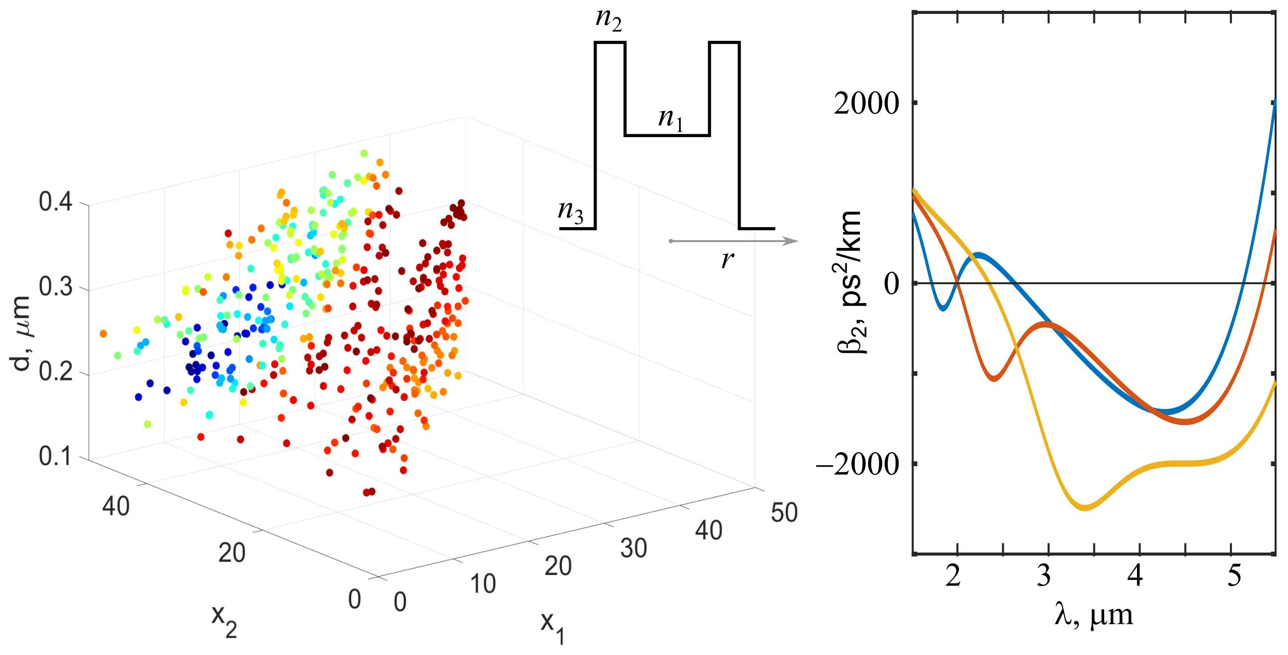
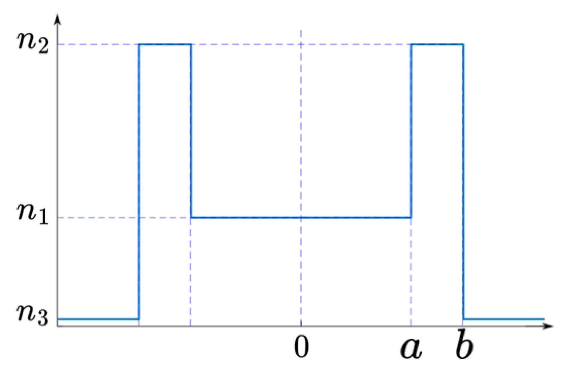
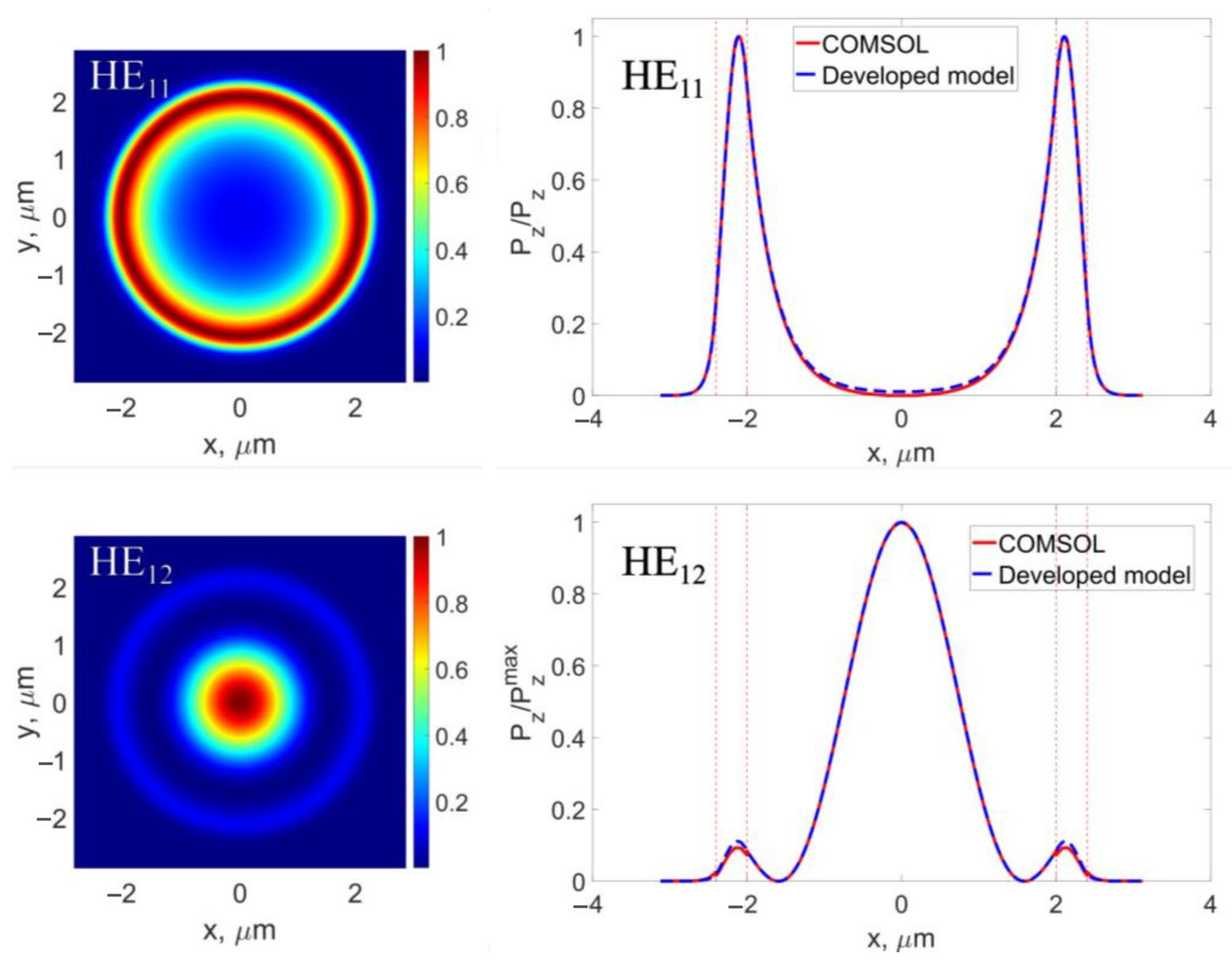
2.1. Fiber Model

Here, we simulated axially symmetrical M-type fibers with a core/ring layer made of As40Se60−x1Tex1/As40Se60−x2Tex2 glasses and cladding made of As40S60 glass (Figure 2a).
Refractive indices n of As40Se60−x1Tex1 glasses can be varied in a wide range by varying tellurium content x1 (examples are shown in Figure 2b) [18]:
n As 40 Se 60 x 1 Te x 1 = n As 40 Se 60 + 0.013 · x 1  
The refractive index dependences of As40Se60 and As40S60 glasses on wavelength are taken from [19] (“AMTIR-2” and “AMTIR-6”, respectively). Note that the technologies for the synthesis of As40Se60−xTex and As40S60 glasses are mature [20]. These glasses have suitable physicochemical properties and are compatible with the manufacture of optical fibers, which was demonstrated experimentally [20], but their ZDWs are located in the mid-IR (Figure 2c). However, thanks to the strong waveguide contribution, the first ZDW of the fibers made of these glasses can be shifted to significantly shorter near-IR wavelengths, which is a subject of our study. We investigate numerical dispersion tailoring by varying four fiber parameters: a, b, x1, and x2.

2.2. Characteristic Equation

We derive a characteristic equation for HE1n mode from the Maxwell equations with allowance for the boundary conditions using the well-known approach [1,21]. For a cylindrical symmetry of an M-type fiber, it is convenient to write the wave equation for the electric and magnetic fields in the cylindrical coordinates (r, φ, z) and, after that, apply the well-described method of separation of variables [1,21]. The electric and magnetic z-field components are as follows [1,21]:
E z r , φ , z , ω = A ω J l k r + B ω N l k r e i l φ e i β z
H z r , φ , z , ω = C ω J l k r + D ω N l k r e i l φ e i β z
where ω is the circular frequency, β is the propagation constant, l = 0, 1, 2,… is the integer, k = n 2 k 0 2 β 2 , k0 = ω/c, c is the speed of light in vacuum, and Jl and Nl are the Bessel and the Neumann functions, respectively. A(ω), B(ω), C(ω), and D(ω) are determined from the boundary conditions. It is also necessary to take into account the natural conditions of the field finiteness at r = 0 and the field decrease at infinity. The expressions for Ez and Hz with allowance for the natural conditions at r = 0 and r = ∞ (after renaming A, B, C, and D to Xj) become
E z = X 1 J l k r e i l φ e i β z ,         k = k 0 n 1 2 n e f f 2 ,     r a
H z = X 2 J l k r e i l φ e i β z ,     r a
E z = ( X 3 J l p r + X 4 N l p r ) e i l φ e i β z ,       p = k 0 n 2 2 n e f f 2 ,     a r b
H z = ( X 5 J l p r + X 6 N l p r ) e i l φ e i β z ,     a r b
E z = X 7 K l q r e i l φ e i β z ,       q = k 0 n e f f 2 n 3 2 ,                 r b
H z = X 8 K l q r e i l φ e i β z ,     r b .
Here and further, neff = β/k0 is the effective refractive index. The radial and φ-components of the fields are found from the Maxwell equations [21]:
E φ = 1 i β 2 k 0 2 n 2 i l E z r k 0 β d H z d r
H φ = k 0 n 2 i β 2 k 0 2 n 2 d E z d r i β l H z k 0 n 2 r
E r = 1 k 0 n 2 l H z r k 0 n H φ
H r = 1 k 0 n 2 l E z r k 0 n E φ
Using the boundary conditions (continuity of Ez, Hz, Eφ, and Hφ for r = a and r = b) and rewriting the equations in matrix form, we obtain
j = 1 8 α i j X j = 0 ,     i = 1 8  
The condition for the existence of a nontrivial solution is the equality to zero of the determinant of the system:
d e t α ^ = 0  
By solving numerically the obtained characteristic Equation (15), we find the effective refractive index neff depending on the parameters of the fiber and the wavelength.
Next, we calculate the group velocity dispersion as follows [1]:
β 2 = d 2 β d ω 2
By substituting the found eigenvalue neff into the coefficients of the system (14), we find the relation Xj, j = 1,…,8. Thus, we determine the structure of the field of the selected mode by substituting the found constants into (4)–(13).
We calculate the Poynting vector as
P z = c 8 π R e E × H * z  
and after that, we calculate the effective mode field area Aeff:
A e f f = + P z d x d y 2 + P z 2 d x d y .
To verify the developed mathematical model, we compared several results of calculations with results of finite element modeling using the COMSOL Multiphysics 5.3a software. As an example, Pz distributions for the HE11 and HE12 modes are shown in Figure 3. So, Figure 3 demonstrates almost ideal coincidence of the results of calculations obtained employing two different approaches. It should be emphasized that Figure 3 also shows that the fundamental mode HE11 is localized near the ring, while the HE12 mode is localized near the core.

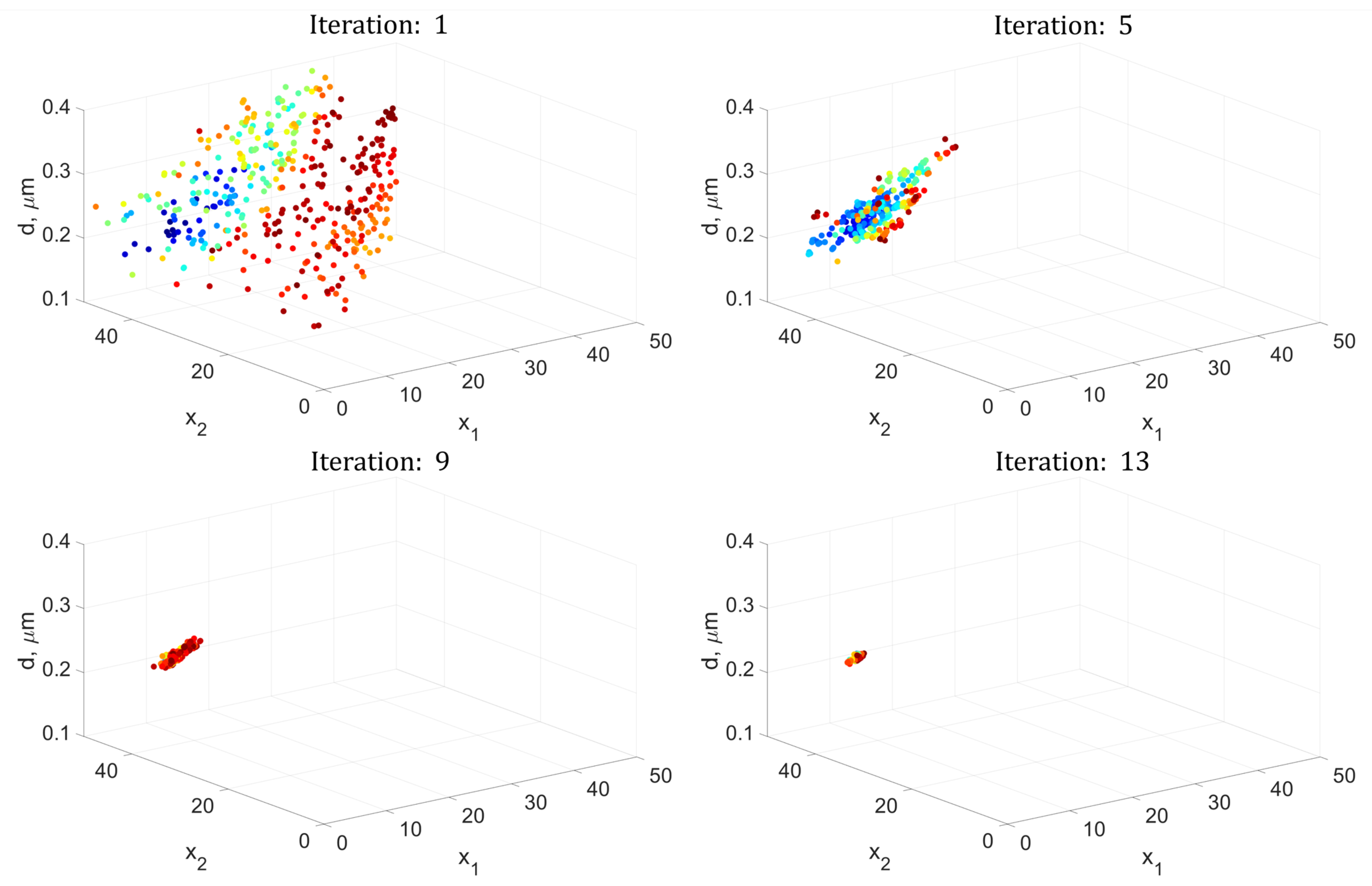
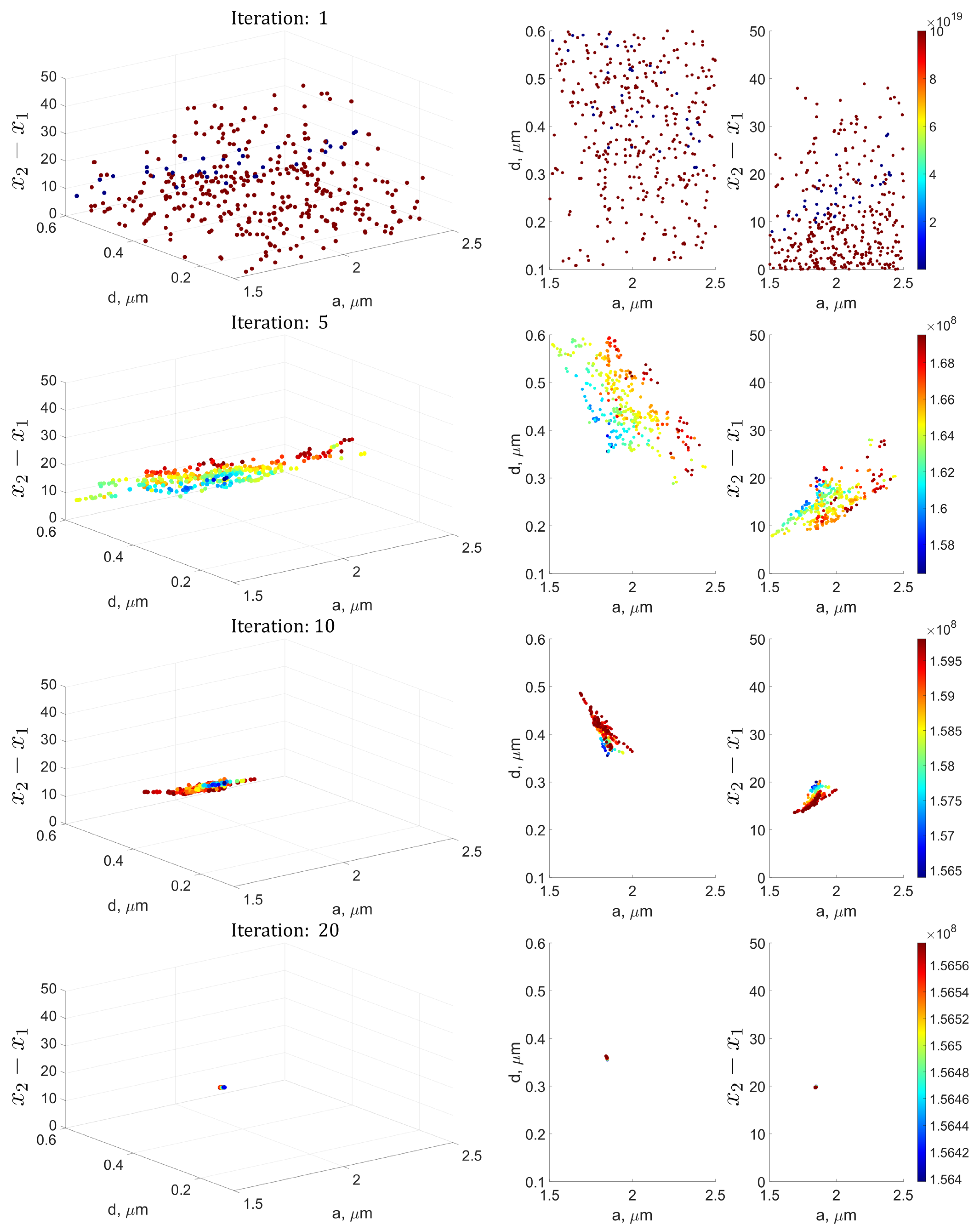
2.3. Modified Genetic Algorithm

The model developed in Section 2.2 allows us to calculate dispersion as a function of wavelength β2(λ) for any set of fiber parameters (a, d, x1, and x2). This opens up an opportunity for dispersion optimization by selecting parameters that allow obtaining the required dependence for a particular problem. Let us introduce the error function F(β2(a, d, x1, x2), β2target), which quantitatively characterizes the difference between the calculated function β2 and the target function β2target. The smaller the value of the error function, the closer the found solution β2 is to the target β2target. In general, the error function can be written as follows:
F β 2 , β 2 t a r g e t = i = 1 N λ μ i β 2 i β 2 t a r g e t   i 2 + G β 2 , β 2 t a r g e t ,
where Nλ is the number of wavelength points (β2(i) = β2i)), μi is the weight coefficients, and G(β2, β2target) is a special component of the error function (the specific form of G(β2, β2target) is selected, taking into account the problem to be solved).
Optimization with respect to four parameters by exhaustive search is inefficient and, hence, impractical. Therefore, a method is needed that would provide the optimal solution with minimal computational costs. One of the known methods is a genetic algorithm that simulates the process of natural selection in wildlife [22]. The essence of the method is the formation and transformation of a population (a set of individuals) where each individual is a potential solution to the problem. For each individual, the error function is calculated [22].
By crossing individuals and their random mutations, a new generation is formed at each iteration of the algorithm, after which the worst individuals (with the largest values of the error function) are discarded. The algorithm stops when it converges to a solution or when a given maximum number of iterations is reached. The convergence criterion, as well as the limit of the number of iterations, are set based on the required accuracy of finding the optimal solution.
In this work, we implemented an MGA similar to that described in [23], which includes the following steps:
  • The formation of an initial population of N individuals, where each individual is a set of randomly generated parameters in the search range: Ij = (aj, dj, x1j, x2j) and j = 1…N;
  • The calculation of the error function Fj = F(Ij) for each individual and sorting the population in ascending order of Fj values (from the best solutions to the worst ones);
  • Algorithm iteration:
    (1)
    Random division of the best 2k individuals into k pairs and crossing in each pair with the formation of 2k new individuals that are added to the population;
    (2)
    Random selection of s individuals and applying the mutation operator to them, changing their parameters randomly. This is performed to provide the widest coverage of the parameter space and to prevent premature stagnation of the algorithm in the local optimum, bypassing the global one;
    (3)
    Sorting the updated population of N + 2k individuals and removing the 2k worst ones (with the largest value of the error function F).
  • Repeating steps (1)–(3) until the maximum number of iterations nmax is reached or the convergence criterion is met.
Crossing of individuals I1 and I2 with the formation of new individuals I1′ and I2′ is performed using the operator X ^ :
I 1 I 2 = X ^ I 1 I 2 = X ^ a 1 d x 11 x 21 a 2 d 2 x 12 x 22 = a 1 d 1 x 11 x 21 a 2 d 2 x 12 x 22 ,  
where the operator X ^ is defined as follows:
X ^ = 1 + κ 2 1 κ 2 1 κ 2 1 + κ 2 ,     κ = 2 u 1 / n + 1 ,     u 0.5 2 2 u 1 / n + 1 ,     u > 0.5
where u 0 ,   1 is a random value and is the parameter that specifies the degree of similarity between children and parents. Smaller values of n lead to a greater probability that the children will strongly differ from the parents.
During mutation, one of the individuals’ parameters is randomly selected and changed as follows:
I j = I j + σ 1 u 1 t / T h ,  
where t is the number of the current iteration, T is the maximum number of iterations, and σ = IjmaxIj or σ = IjIjmin with equal probability (Ijmax and Ijmin are the largest and smallest value of the variable parameter in the current population, respectively). This type of mutation operator allows us to make the process uneven: at the initial steps of the algorithm, the degree of mutation is the highest, which is important for the most complete search in the parameter space and the reduction of the probability of premature convergence; at the final stage, the mutations are minimal, which makes it possible to reduce the scatter of individuals upon convergence to the final solution. The parameter h allows us to set the degree of this unevenness of the mutation process; the larger the h, the more the nature of the process changes during the operation of the algorithm.

3. Results

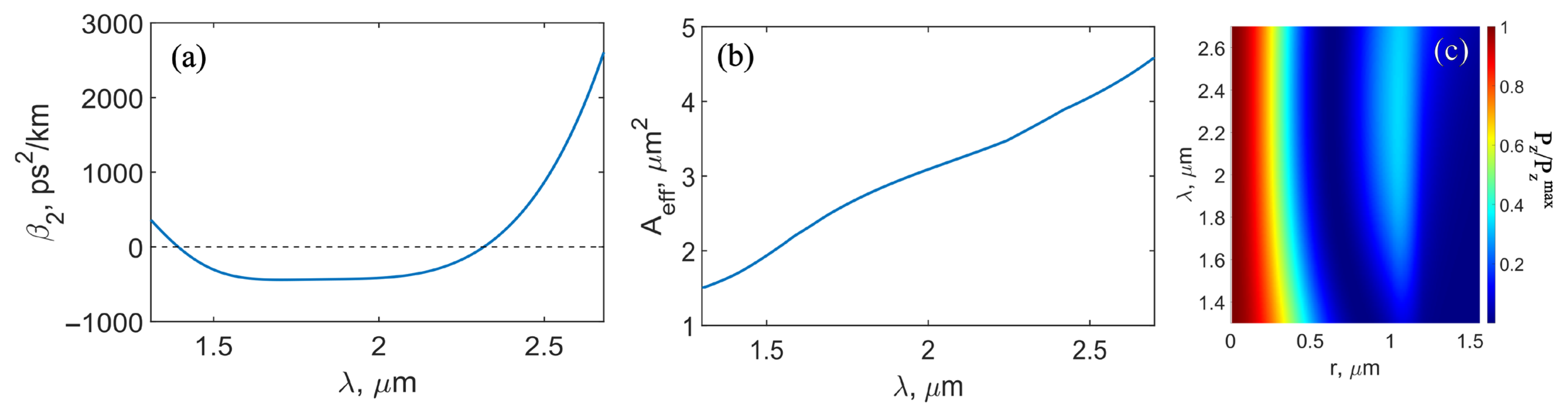
3.1. Dependences of Dispersion on Parameters

We studied the properties of the HE12 mode in detail. Before optimizing the dispersion curves using MGA with respect to four parameters (a, d, x1, and x2) for achieving the desired dispersion profile, we performed a series of numerical simulations in which some parameters were fixed. This was required for a better understanding of the tendencies and for finding patterns in the behavior of dispersion curves when changing each parameter. This also allowed us to determine the range of parameters for executing MGA.

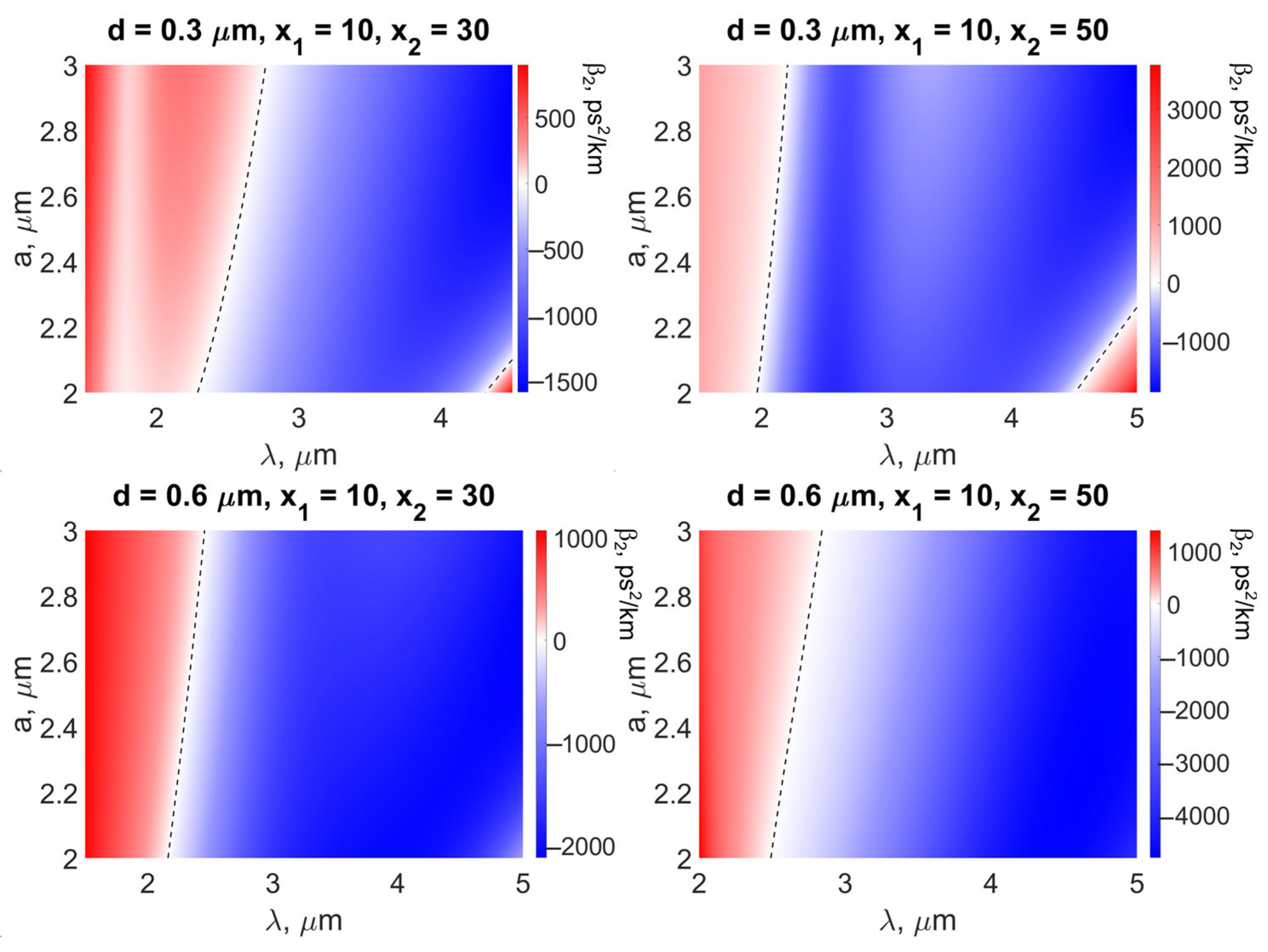
3.1.1. Fixed d, x1, and x2; Varied a

As the first illustration, we considered x1 = 10, d = 0.3, 0.6 μm, and x2 = 30, 50. Thus, there were four possible combinations. We calculated β2 for each combination (d = 0.3 μm and x2 = 30; d = 0.3 μm and x2 = 50; d = 0.6 μm and x2 = 30; and d = 0.6 μm and x2 = 50) by varying a in the range from 2 to 3 μm. The results are presented in Figure 4. Hereinafter, the black dotted lines correspond to ZDWs. It is seen that for the chosen parameters, anomalous dispersion can start from 2 to 2.7 μm. This result was obtained thanks to the significant waveguide contribution. The smaller a is, the shorter the first ZDW. Therefore, to achieve the minimum ZDW, it is necessary to reduce the size of the core. However, this narrows the range of anomalous dispersion (the second ZDW appears for small a). It is also seen that the thicker the ring layer, the longer the first ZDW.

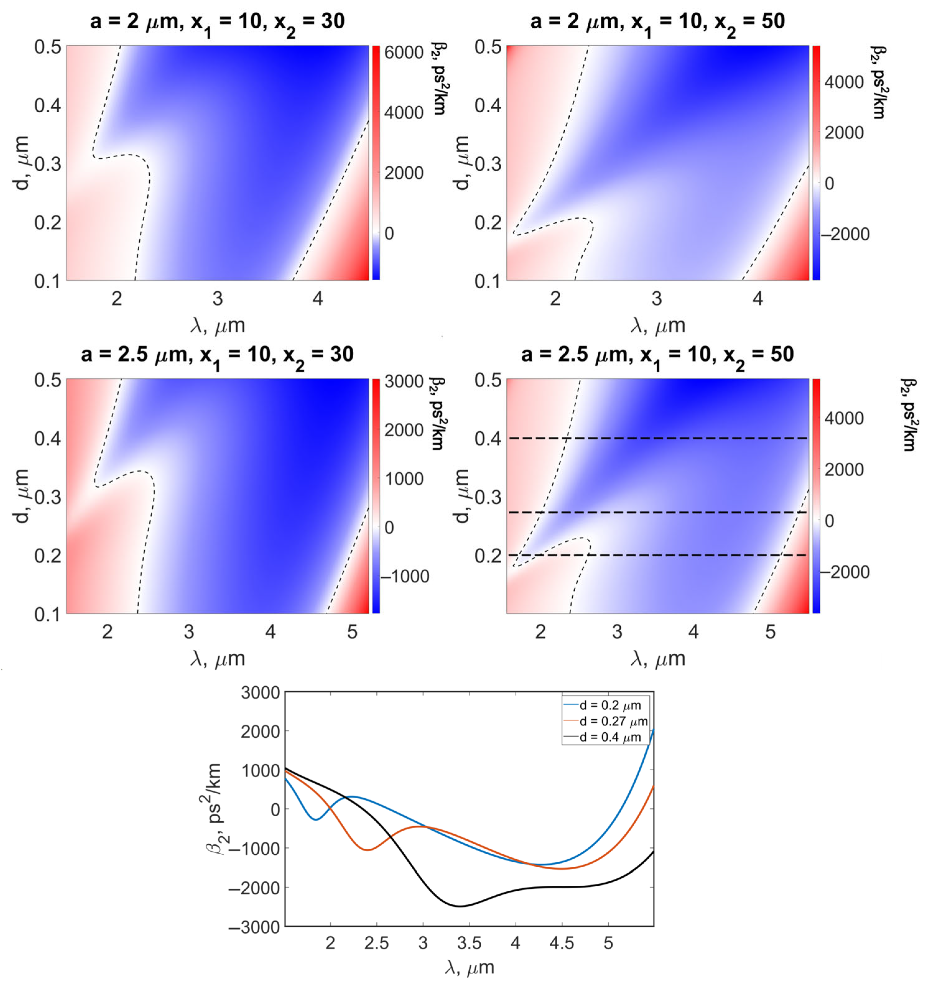
3.1.2. Fixed a, x1, and x2; Varied d

Next, we set x1 = 10, a = 2, 2.5 μm, and x2 = 30, 50. Figure 5 demonstrates β2 as a function of wavelength for four combinations of parameters. We found an interesting feature, namely, that the dispersion dependences can be more complex than in Figure 4. For the considered parameters, they can have from one to four ZDWs in the 1.5–5.5 μm range (see Figure 5, the lowest subplot). However, the dispersive curves with four ZDWs exist in a narrow range of d. Such exotic dispersion was known for fundamental modes of fibers and waveguides of special design [24,25], but it was not reported for M-type fibers. For some problems of nonlinear optical conversion, β2 with four ZDWs may be required. So, the HE12 mode of M-type fibers can also be optimized for this purpose.

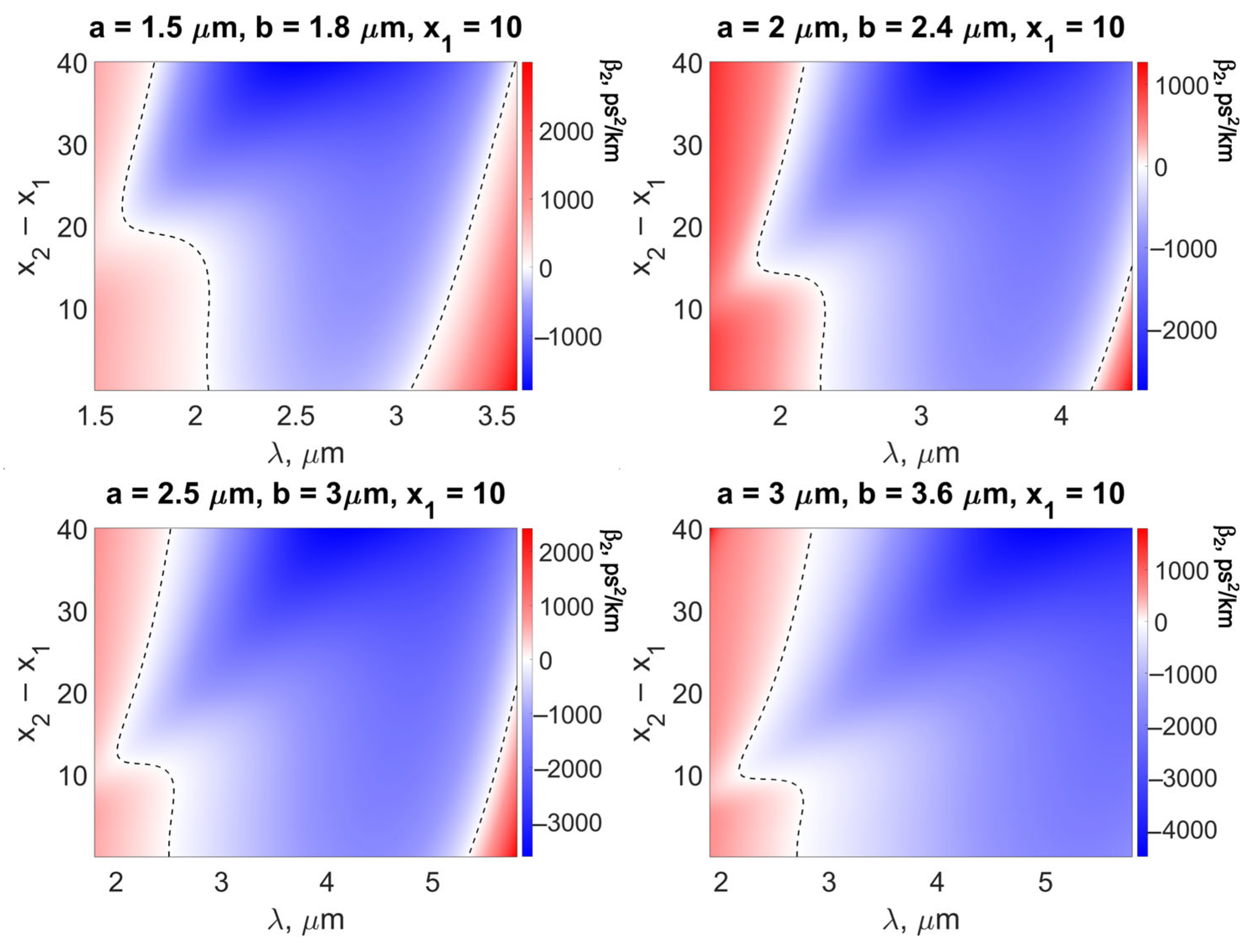
3.1.3. Fixed a, d, and x1; Varied x2
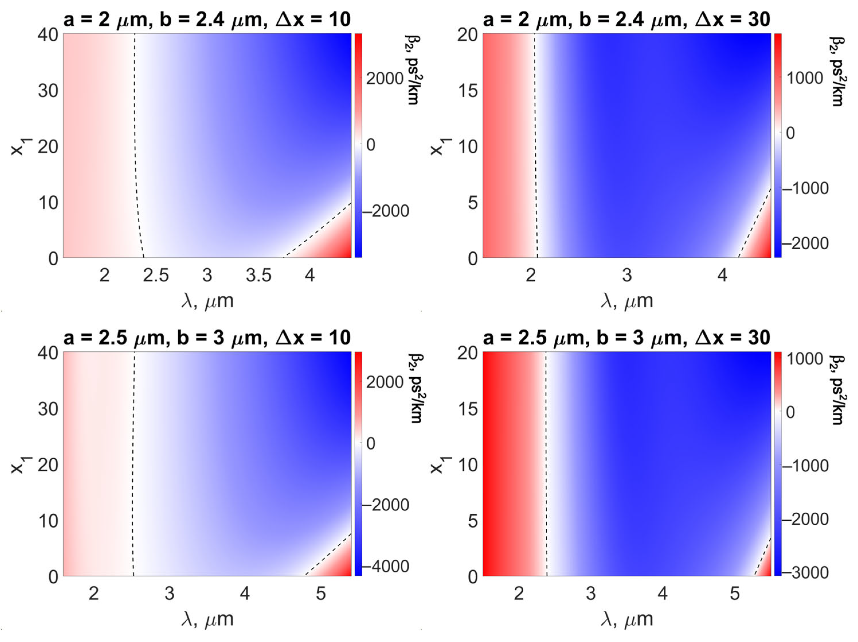
Further, we fixed a, d, and x1 and varied the refractive index difference between the core and the ring layer. The dispersion β2 calculated as a function of λ is presented in Figure 6. The dispersion characteristics have one or two ZDWs in the considered spectral range. We note an interesting feature for this series of numerical simulations: the dependence of the ZDW on (x2x1) is nonmonotonic; there is the value of (x2x1) corresponding to the minimum of the first ZDW. It is seen in Figure 6 that the first ZDW can be shifted to wavelengths shorter than 2 μm. The second ZDW shifts to longer wavelengths with increasing (x2x1).

3.1.4. Fixed a, d, and (x2x1); Varied x1

We also simulated M-type fibers with fixed a, b, and (x2x1) assuming varied x1. The corresponding dispersion is shown in Figure 7. We can conclude from this figure that the first ZDW is almost independent of x1, but the smaller x1 is, the shorter the second ZDW.

3.2. Dispersion Profiles Tailored with Modified Genetic Algorithm

After studying the general patterns of dispersion behavior when changing one of the parameters of the problem with the remaining parameters fixed, we wondered about the possibility of reverse-designing fibers with desired characteristics. In Section 3.2.1 and Section 3.2.2, we will present two different examples of finding M-type fiber parameters using MGA.

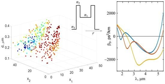
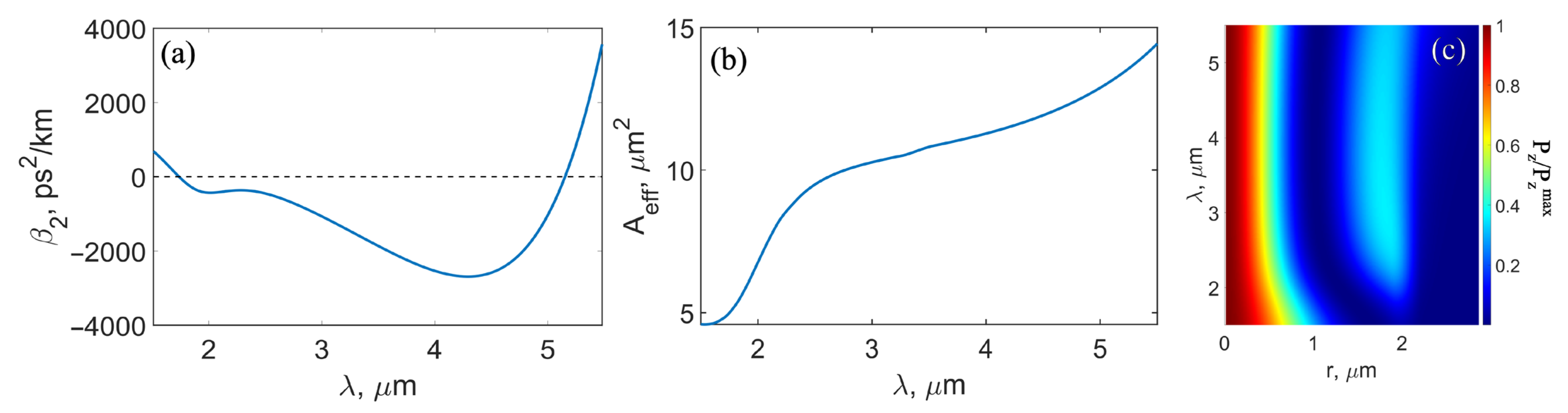
3.2.1. Minimizing the First ZDW with MGA

The first problem solved with the help of MGA was minimizing the first ZDW for the HE12 mode. As can be seen in Figure 5 (right column), there are fiber parameters providing a ZDW~1.6 μm. However, for some tasks, it might be useful to have a fiber with anomalous dispersion at wavelengths near 1.55 μm corresponding to standard erbium-doped fiber lasers. Therefore, further optimization is required. As shown in Section 3.1, the short-wavelength ZDW shift can be achieved by decreasing the core radius a. However, the core size can only be reduced to a certain value limited by a cutoff wavelength λcutoff for HE12 mode. As a result, it is necessary to set a condition on λcutoff and search for the minimum of the ZDW, taking this condition into account. Further optimization was carried out for λcutoff > 3 μm.
We fixed a = 1 μm since the core size has a predominant effect on the cutoff wavelength. For this core radius, λcutoff belongs to the interval from 3 to 4 μm depending on other parameters. We made optimization for three parameters, as follows: d (0.1 μm, 0.4 μm), x1, x2  {[0, 50]|x2 > x1}. To minimize the computational complexity of the MGA algorithm, the dispersion was calculated at four points: λ = 1.3 μm, 1.4 μm, 1.5 μm, and 1.6 μm. A large absolute value of the anomalous dispersion was set as the objective function. The MGA parameters providing optimal balance between the speed of finding a solution and minimizing the tendency to premature convergence are as follows:
  • N = 400 is the number of individuals in the population;
  • k = 40 is the number of pairs of individuals that give offspring at each iteration (the same number of individuals was eliminated at each iteration);
  • n = 5 is the parameter of the crossing operator;
  • T = 100 and h = 5 are mutation operator parameters.
The process of the MGA execution was visualized for clarity and convergence control. Each individual is represented by a point in the parameter space (d, x1, and x2); the color of the point shows the value of the error function for this individual (Figure 8). The algorithm converged fairly quickly. A little more than 10 iterations were sufficient for this problem.
We found that a ZDW = 1.395 μm is achieved for the following set of parameters: a = 1 μm; b = 1.201 μm; x1 = 11.48; and x2 = 47.53. The dispersion dependence on wavelength for these M-type fiber parameters is plotted in Figure 9a. The second ZDW is 2.317 μm. Thus, the width of the anomalous dispersion region is 0.92 μm. The dispersion is almost flat (near −450 ps2/km) in the 1.55–2.1 μm range. Since the effective mode area is also very important for the nonlinear optical pulse conversion, we plotted Aeff in Figure 9b. The Poynting vector, depending on radial coordinate and wavelength, is also demonstrated in Figure 9c.

3.2.2. Obtaining Anomalous Dispersion in the 2–5 μm Range with MGA

For developing mid-IR light sources at 2–5 μm, for example, frequency-tunable Raman soliton sources pumped by a thulium-doped fiber laser at 2 μm, anomalous dispersion is required at these wavelengths. Therefore, the second task in the dispersion tailoring with the MGA was to find the M-type fiber parameters providing anomalous dispersion of the HE12 mode in the entire spectral range of 2–5 μm. The main difference in comparison with the previous case is that here, all four parameters were optimized (the core radius a was not fixed). The ranges of parameter variation were selected based on the results of the simulation presented in Section 3.1. We also set the requirement λcutoff > 5 μm. We assumed a ∈ (1.5 μm, 2.5 μm); d ∈ (0.1 μm, 0.6 μm); and x1, x2 ∈ {[0, 50]|x2 > x1}.
The MGA parameters were left unchanged, but a different error function was used. This is due to the need to optimize dispersion simultaneously in two directions: to shift the first ZDW to the short-wavelength region λ < 2 μm and to expand the range of anomalous dispersion to the region λ > 5 μm. In this case, when comparing two solutions meeting the condition β2 < 0 over the entire interval λ ∈ (2 μm, 5 μm), priority should be given to the set of parameters providing the smaller ZDW. Thus, the values of β2 near the ZDW should be taken into account with the highest weight. This is achieved by introducing weight coefficients μi in the expression (19). They were calculated as follows:
μ i = 1 2 + M i 2 M 1 q
Here, M is the number of points of the function β2(λ), and the optimal value of the parameter q is determined empirically based on the results given by the MGA for various q. The second important condition is the need to cut off sets of parameters for which the dispersion is anomalous only in part of the 2–5 μm interval. However, it is not advisable to discard them during the MGA operation since such individuals that are not suitable as a solution to the problem can generate suitable ones due to crossing and mutations. Therefore, for each value β2 > 0 in the wavelength range of 2–5 μm, a special large addition G(β2, β2target) in the expression (19) was taken into account.
Visualization of the MGA operation is shown in Figure 10. In the initial population, most individuals do not satisfy the anomalous dispersion condition over the entire required interval, and they are indicated by the red dots. The blue dots are solutions that satisfy the condition, for which the error function is much smaller. At the fifth iteration, all individuals in the population have anomalous dispersion over the entire interval, and further selection takes place among potentially successful solutions. Ultimately, the algorithm converges to the following set of parameters: a = 1.8484 μm, b = 2.204 μm, x1 = 29.46, and x2 = 49.46. The corresponding dispersion dependence on wavelength is demonstrated in Figure 11a. For the found solution, the first ZDW is 1.735 μm, and the second ZDW is 5.155 μm. The effective mode area and Poynting vector for these fiber parameters are also plotted in Figure 11b,c, respectively. Note that Aeff changes very slowly at the wavelength of 2.5–5 μm, which is an advantage for nonlinear pulse conversion. Note that found x2 = 49.46 is close to the upper limit of the considered range. The glass with a similar tellurium concentration was demonstrated in [18]. However, if, for fiber manufacturing, specific technological conditions do not allow the creation of glass with the desired physical and chemical properties at such a concentration, the optimization problem should be solved anew, taking into account technical capabilities.

4. Discussion and Conclusions

In this work, we proposed and theoretically investigated M-type fibers with As40Se60−x1Tex1/As40Se60−x2Tex2/As40S60 glass core/ring layer/cladding. These glasses have suitable physicochemical properties and are compatible with the manufacture of optical fibers [20]. By varying the tellurium content in the glass composition, it is possible to strongly affect the refractive index difference between the core of radius a and the ring layer of thickness d [18]. We considered the HE12 mode localized near the core rather than the fundamental mode HE11 localized near the ring layer. We demonstrated that, by controlling four fiber parameters (a, d, x1, and x2), the ZDW of HE12 mode can be effectively shifted to the near-IR (while for As-Se-Te glasses, material ZDW > 7 μm). Note that it was previously demonstrated through numerical simulation by the finite-element method that for M-type Ge-As-Se/As-Se chalcogenide fibers, the ZDW can be only slightly shorter than 3 μm [17]. Here, we proposed smart designs and optimization of M-type As-Se-Te/As-S chalcogenide fibers, providing the first ZDW shorter than 2 μm and even shorter than 1.55 μm. This will make it possible to develop broadband light converters in the anomalous dispersion regimes using standard fiber laser pump sources at 2 μm and even at 1.55 μm.
We derived the characteristic equation for HE1n modes of M-type fiber from the Maxwell equations. We developed a numerical code for its solution and for the calculation of the group velocity dispersion, the Poynting vector, and the effective mode area. The developed model was verified by comparing the results with the data obtained by finite element modeling. We studied in detail the properties of the HE12 mode. We performed a series of numerical simulations by varying some parameters to understand the tendencies and to find patterns in the dispersion behavior. We showed that thanks to the strong waveguide contribution, it is possible to obtain from one to four ZDWs in the 1.5–5.5 μm range.
We proposed dispersion tailoring using MGA and demonstrated its applicability for two certain problems. In the first one, we optimized three fiber parameters (d, x1, and x2) and shifted the first ZDW of the HE12 mode to a wavelength shorter than 1.55 μm. We found the parameters providing a ZDW = 1.395 μm and the 0.92 μm width of the anomalous dispersion range. In the second problem solved with MGA, we optimized four fiber parameters (a, d, x1, and x2) and tried to design M-type fiber with anomalous dispersion in the spectral range wider than 2–5 μm. We found parameters providing the first ZDW of 1.735 μm and the second ZDW of 5.155 μm (3.4 μm width of the anomalous dispersion range).
Note that MGA can be successfully applied for designing various dispersion characteristics of chalcogenide M-type fibers, including quite exotic ones with several ZDWs. Moreover, the developed model can be used to construct M-type fibers with desired properties made of different glasses (not only chalcogenide ones). The proposed approach can also be generalized for the inverse design of other types of fibers and can have some advantages over finite-element modeling, especially when considering a lot of variable parameters. It should also be noted that we used a specific MGA implementation suitable for our problem. However, there are other promising specific implementations for solving different optimization problems. For example, in the near future, genetic algorithms could be calculated with an optical computer based on the Ising model, which will significantly reduce computation time [26].

Author Contributions

Conceptualization, N.I.S. and E.A.A.; methodology, N.I.S.; software, N.I.S.; validation, N.I.S., A.V.A. and E.A.A.; formal analysis, N.I.S. and A.V.A.; investigation, N.I.S.; data curation, N.I.S.; writing—original draft preparation, N.I.S. and E.A.A.; writing—review and editing, A.V.A.; visualization, N.I.S. and E.A.A.; supervision, E.A.A. All authors have read and agreed to the published version of the manuscript.

Funding

The work was supported by the Center of Excellence «Center of Photonics» funded by the Ministry of Science and Higher Education of the Russian Federation, contract No. 075-15-2022-316.

Data Availability Statement

Data underlying the results presented in this article may be obtained from the authors upon reasonable request.

Conflicts of Interest

The authors declare no conflict of interest.

References

  1. Agrawal, G.P. Nonlinear Fiber Optics, 6th ed.; Elsevier: Amsterdam, The Netherlands, 2019. [Google Scholar]
  2. Agrawal, G.P. Applications of Nonlinear Fiber Optics; Elsevier: Amsterdam, The Netherlands, 2001. [Google Scholar]
  3. Jeunhomme, L.B. Single-Mode Fiber Optics: Prinicples and Applications; Routledge: Oxfordshire, UK, 2019. [Google Scholar]
  4. Tao, G.; Ebendorff-Heidepriem, H.; Stolyarov, A.M.; Danto, S.; Badding, J.V.; Fink, Y.; Ballato, J.; Abouraddy, A.F. Infrared Fibers. Adv. Opt. Photonics 2015, 7, 379–458. [Google Scholar] [CrossRef]
  5. Shiryaev, V.S.; Churbanov, M.F. Recent Advances in Preparation of High-Purity Chalcogenide Glasses for Mid-IR Photonics. J. Non-Cryst. Solids 2017, 475, 1–9. [Google Scholar] [CrossRef]
  6. Bodrov, S.; Sergeev, Y.; Burova, E.; Korytin, A.; Murzanev, A.; Romashkin, A.; Stepanov, A. Cubic Nonlinearity of Tellurite and Chalcogenide Glasses: Terahertz-Field-Induced Second Harmonic Generation vs. Optical Kerr Effect. Appl. Sci. 2022, 12, 11608. [Google Scholar] [CrossRef]
  7. Anashkina, E.A.; Sorokin, A.A.; Andrianov, A.V. Ultrashort Pulse Retrieval from Experimental Spectra Transformed in Chalcogenide and Silica Fibers. Fibers 2022, 10, 98. [Google Scholar] [CrossRef]
  8. Niang, A.; Mansuryan, T.; Krupa, K.; Tonello, A.; Fabert, M.; Leproux, P.; Modotto, D.; Egorova, O.N.; Levchenko, A.E.; Lipatov, D.S.; et al. Spatial Beam Self-Cleaning and Supercontinuum Generation with Yb-Doped Multimode Graded-Index Fiber Taper Based on Accelerating Self-Imaging and Dissipative Landscape. Opt. Express 2019, 27, 24018. [Google Scholar] [CrossRef] [PubMed]
  9. Neves, I.V.; Fernandes, A.S.C. Modal Characteristics for W-Type and M-Type Dielectric Profile Fibers. Microw. Opt. Technol. Lett. 1999, 22, 398–405. [Google Scholar] [CrossRef]
  10. Yeh, P.; Yariv, A.; Marom, E. Theory of Bragg Fiber. J. Opt. Soc. Am. 1978, 68, 1196. [Google Scholar] [CrossRef]
  11. Ghosh, S.; Dasgupta, S.; Varshney, R.K.; Richardson David, J.; Pal, B.P. Design of a Bragg Fiber with Large Mode Area for Mid-Infrared Applications. Opt. Express 2011, 19, 21295. [Google Scholar] [CrossRef] [PubMed]
  12. Dudley, J.M.; Genty, G.; Coen, S. Supercontinuum Generation in Photonic Crystal Fiber. Rev. Mod. Phys. 2006, 78, 1135–1184. [Google Scholar] [CrossRef]
  13. Bufetov, I.A.; Kosolapov, A.F.; Pryamikov, A.D.; Gladyshev, A.V.; Kolyadin, A.N.; Krylov, A.A.; Yatsenko, Y.P.; Biriukov, A.S. Revolver Hollow Core Optical Fibers. Fibers 2018, 6, 39. [Google Scholar] [CrossRef]
  14. Cai, D.; Xie, Y.; Guo, X.; Wang, P.; Tong, L. Chalcogenide Glass Microfibers for Mid-Infrared Optics. Photonics 2021, 8, 497. [Google Scholar] [CrossRef]
  15. Aleshkina, S.S.; Yashkov, M.V.; Bubnov, M.M.; Guryanov, A.N.; Likhachev, M.E. Asymptotically Single-Mode Hybrid Fiber for Dispersion Management Near 1 μm. IEEE J. Sel. Top. Quantum Electron. 2018, 24, 0901608. [Google Scholar] [CrossRef]
  16. Aleshkina, S.S.; Yatsenko, Y.P.; Salganskii, M.Y.; Lipatov, D.S.; Senatorov, A.K.; Tausenev, A.V.; Shepelev, D.V.; Bubnov, M.M.; Guryanov, A.N.; Likhachev, M.E. High-Peak-Power Femtosecond Pulse Generation by Nonlinear Compression in a Yb-Doped Hybrid Fiber. IEEE Photonics J. 2019, 11, 7103411. [Google Scholar] [CrossRef]
  17. Jain, D.; Markos, C.; Benson, T.M.; Seddon, A.B.; Bang, O. Exploiting Dispersion of Higher-Order-Modes Using M-Type Fiber for Application in Mid-Infrared Supercontinuum Generation. Sci. Rep. 2019, 9, 8536. [Google Scholar] [CrossRef] [PubMed]
  18. El-Den, M.B.; El-Nahass, M.M. Optical Properties of AsSe1.5−xTex Glassy System. Opt. Laser Technol. 2003, 35, 335–340. [Google Scholar] [CrossRef]
  19. Amorphous Materials Inc. Available online: http://www.amorphousmaterials.com (accessed on 18 October 2023).
  20. Anashkina, E.A.; Shiryaev, V.S.; Snopatin, G.E.; Muraviev, S.V.; Kim, A.V. On the Possibility of Mid-IR Supercontinuum Generation in As-Se-Te/As-S Core/Clad Fibers with All-Fiber Femtosecond Pump Source. J. Non-Cryst. Solids 2018, 480, 38–42. [Google Scholar] [CrossRef]
  21. Snyder, A.W.; Love, J.D. Optical Waveguide Theory; Chapman and Hall: London, UK, 1983. [Google Scholar]
  22. Mitchell, M. An Introduction to Genetic Algorithms; MIT: Cambridge, MA, USA, 1998. [Google Scholar]
  23. Wang, Z.; Ye, F.; Li, Q. Modified Genetic Algorithm for High-Efficiency Dispersive Waves Emission at 3 μm. Opt. Express 2022, 30, 2711. [Google Scholar] [CrossRef] [PubMed]
  24. Zhang, L.; Lin, Q.; Yue, Y.; Yan, Y.; Beausoleil, R.G.; Willner, A.E. Silicon Waveguide with Four Zero-Dispersion Wavelengths and Its Application in on-Chip Octave-Spanning Supercontinuum Generation. Opt. Express 2012, 20, 1685–1690. [Google Scholar] [CrossRef] [PubMed]
  25. Deb, R.; Maji, P.S. Investigation of Parametric Gain and Bandwidth of Tellurite Hybrid Micro-Structured Fiber with Four ZDWs. Opt. Quantum Electron. 2021, 53, 717. [Google Scholar] [CrossRef]
  26. Honjo, T.; Sonobe, T.; Inaba, K.; Inagaki, T.; Ikuta, T.; Yamada, Y.; Kazama, T.; Enbutsu, K.; Umeki, T.; Kasahara, R.; et al. 100,000-Spin Coherent Ising Machine. Sci. Adv. 2021, 7, eabh0952. [Google Scholar] [CrossRef] [PubMed]
Figure 1. Refractive index profile of M-type fiber.
Fibers 11 00089 g001
Figure 2. (a) Cross section scheme of considered M-type fibers. Refractive indices (b) and dispersions (c) of chalcogenide glasses.
Fibers 11 00089 g002
Figure 3. Examples of calculated Poynting vector Pz for HE11 (top) and HE12 (bottom) modes for M-type fiber parameters a = 2 μm, b = 2.4 μm, x1 = 10, and x2 = 30.
Fibers 11 00089 g003
Figure 4. Dispersion as a function of wavelength λ and core radius a.
Fibers 11 00089 g004
Figure 5. Dispersion as a function of wavelength λ and ring thickness d (top and middle). Examples of dispersion with one, two, and four ZDWs (bottom) corresponding to horizontal lines in the right panel of the middle row.
Fibers 11 00089 g005
Figure 6. Dispersion as a function of wavelength λ and refractive index difference (x2x1).
Fibers 11 00089 g006
Figure 7. Dispersion as a function of wavelength λ and core refractive index x1.
Fibers 11 00089 g007
Figure 8. Visualization of MGA execution for minimizing the first ZDW. For red dots the error is maximum, for blue dots the error is minimum.
Fibers 11 00089 g008
Figure 9. Dispersion with the first ZDW at 1.395 μm (a) and effective mode area (b) of HE12 mode calculated for a = 1 μm; b = 1.201 μm; x1 = 11.48; and x2 = 47.53. (c) Poynting vector of HE12 mode depending on radial coordinate and wavelength.
Fibers 11 00089 g009
Figure 10. Visualization of MGA execution for finding broad range of anomalous dispersion.
Fibers 11 00089 g010
Figure 11. Dispersion with the first ZDW at 1.735 μm and the second ZDW at 5.155 μm (a) and effective mode area (b) of HE12 mode calculated for a = 1.8484 μm, b = 2.204 μm, x1 = 29.46, and x2 = 49.46. (c) Poynting vector of HE12 mode depending on radial coordinate and wavelength.
Fibers 11 00089 g011
Disclaimer/Publisher’s Note: The statements, opinions and data contained in all publications are solely those of the individual author(s) and contributor(s) and not of MDPI and/or the editor(s). MDPI and/or the editor(s) disclaim responsibility for any injury to people or property resulting from any ideas, methods, instructions or products referred to in the content.

