
Ductility and Stiffness of Laminated Veneer Lumber Beams Strengthened with Fibrous Composites


Abstract
:1. Introduction
- failure occurs after large deformations that will alert users in the event of unforeseen loads (e.g., increased snow loads);
- the load capacity of the structure is increased in relation to the values estimated based on elastic analysis (by redistributing stresses and forces);
- reliability of the structure is increased. Ductility is a way of ensuring the possibility of transferring increased displacements and rotations in the event of failure of one of the system’s elements;
- energy dissipation under seismic loads is ensured.
2. Materials and Methods
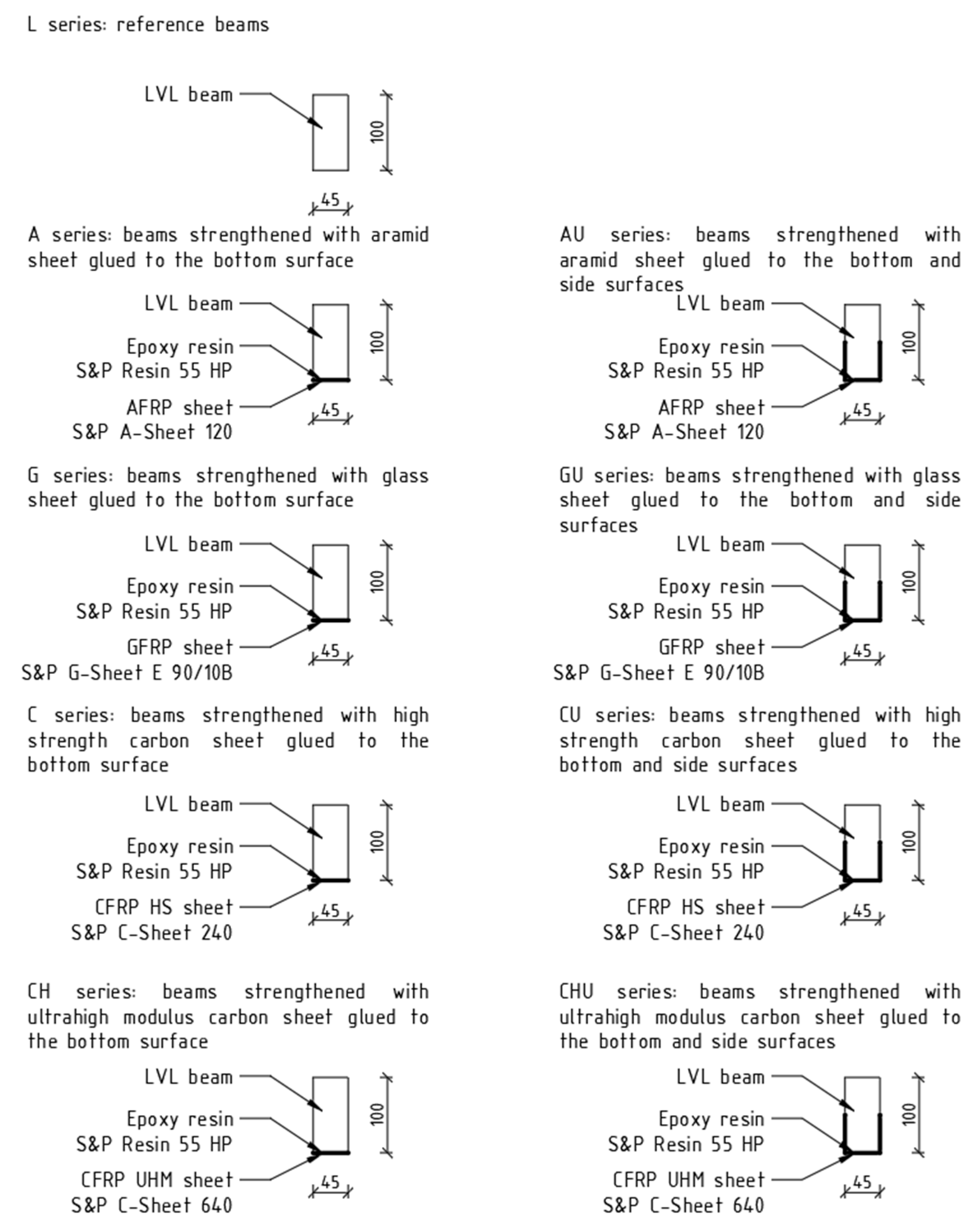
- LVL series—reference beams;
- LVLC series—beams strengthened with 4.5 cm wide high strength carbon sheet glued to the bottom surface (reinforcement ratio, ρt = 0.33%);
- LVLCU series—beams strengthened with 14.5 cm wide high strength carbon sheet glued to the bottom and side surfaces (reinforcement ratio, ρt = 1.07%);
- LVLCH series—beams strengthened with 4.5 cm wide ultra-high modulus carbon sheet glued to the bottom surface (reinforcement ratio, ρt = 0.19%);
- LVLCHU series—beams strengthened with 14.5 cm wide ultra-high modulus carbon sheet glued to the bottom and side surfaces, ρt = 0.61%);
- LVLA series—beams strengthened with 4.5 cm wide aramid sheet glued to the bottom surface itki (reinforcement ratio, ρt = 0.20%);
- LVLAU series—beams strengthened with 14.5 cm wide aramid sheet glued to the bottom and side surfaces (reinforcement ratio, ρt = 0.64%);
- LVLG series—beams strengthened with 4.5 cm wide glass sheet glued to the bottom surface (reinforcement ratio, ρt = 0.31%);
- LVLGU series—beams strengthened with 14.5 cm wide glass sheet glued to the bottom and side surfaces (reinforcement ratio, ρt = 0.99%).
2.1. Materials
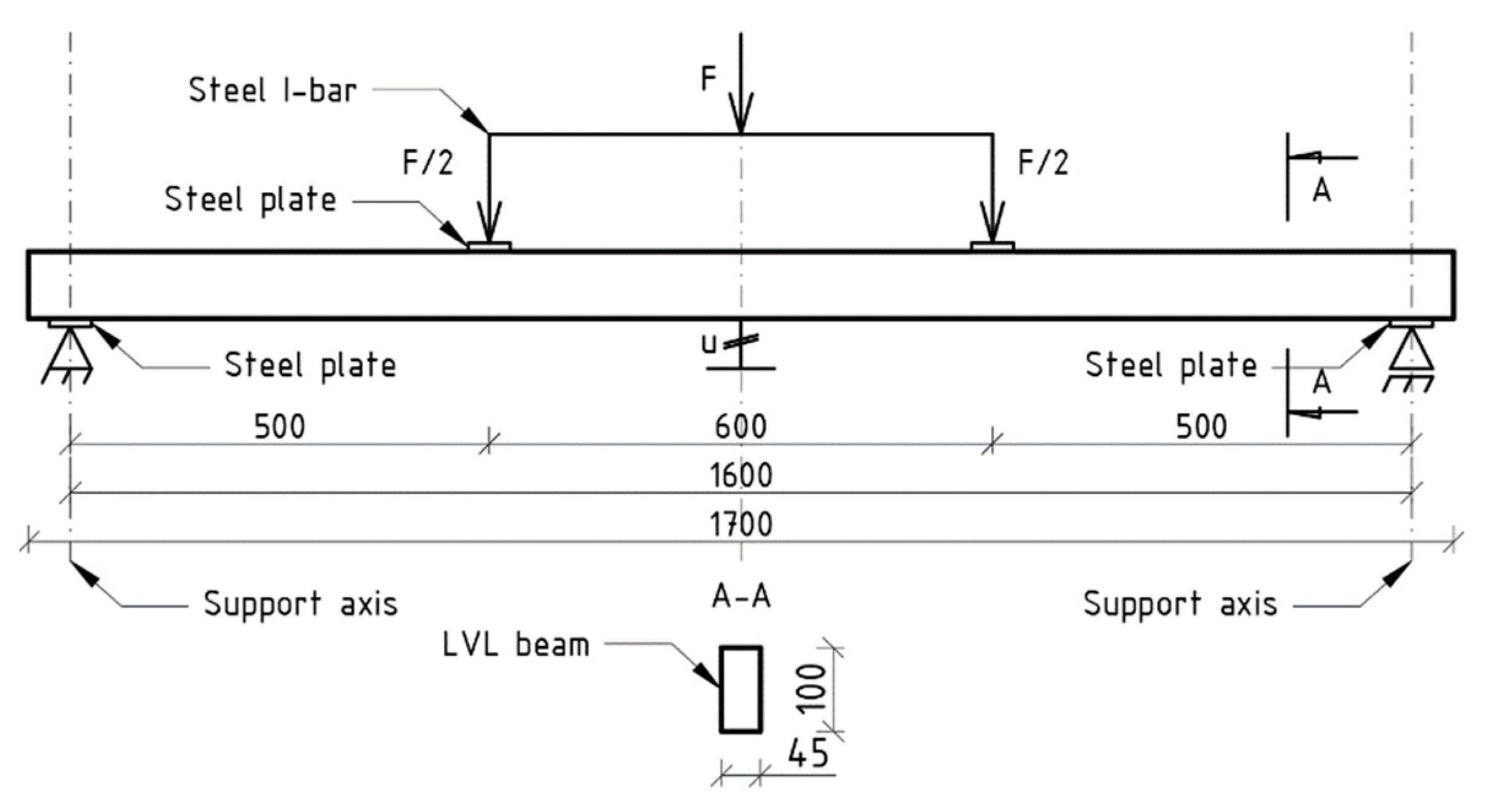
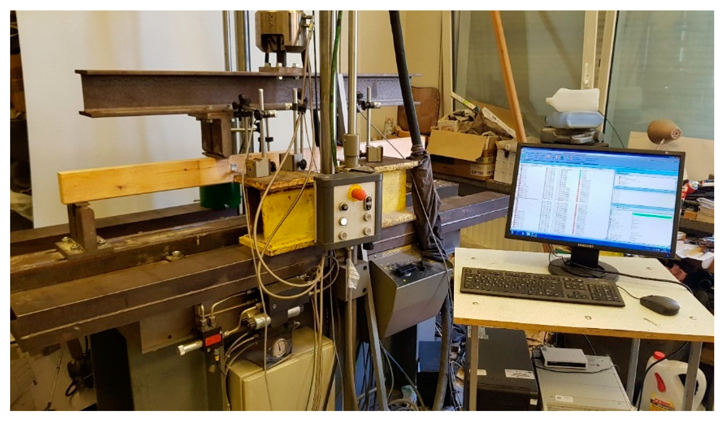
2.2. Methods
- the loading force value F [N], displacement of the hydraulic actuator head us [mm] (which can be equated with the displacement of the beam at the points of application of the concentrated load) and test time t [s]—with the use of a computer set connected to the universal testing machine MTS-320;
- deflection in the center of the beam at the extreme lower fibers under tension u [mm]—measurement performed using an inductive sensor of the Hottinger Baldwin Messtechnik system;
- failure mode—description and photographic documentation.
3. Results
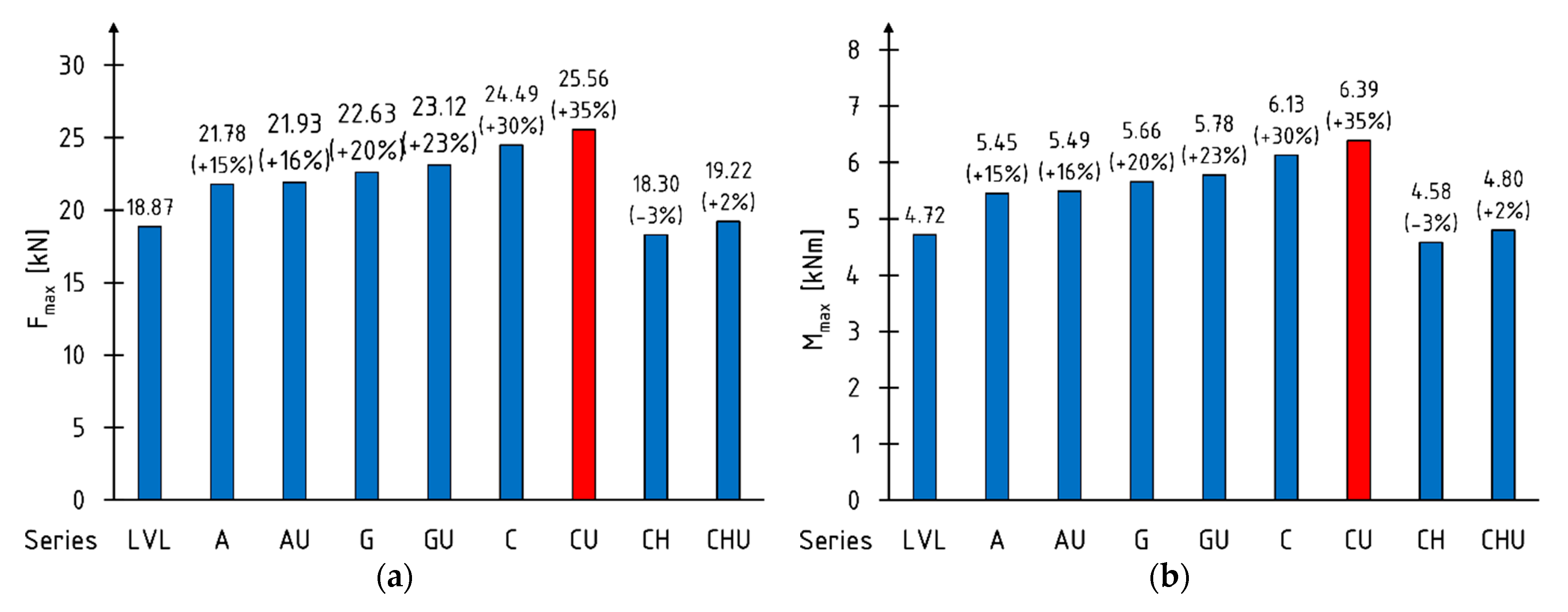
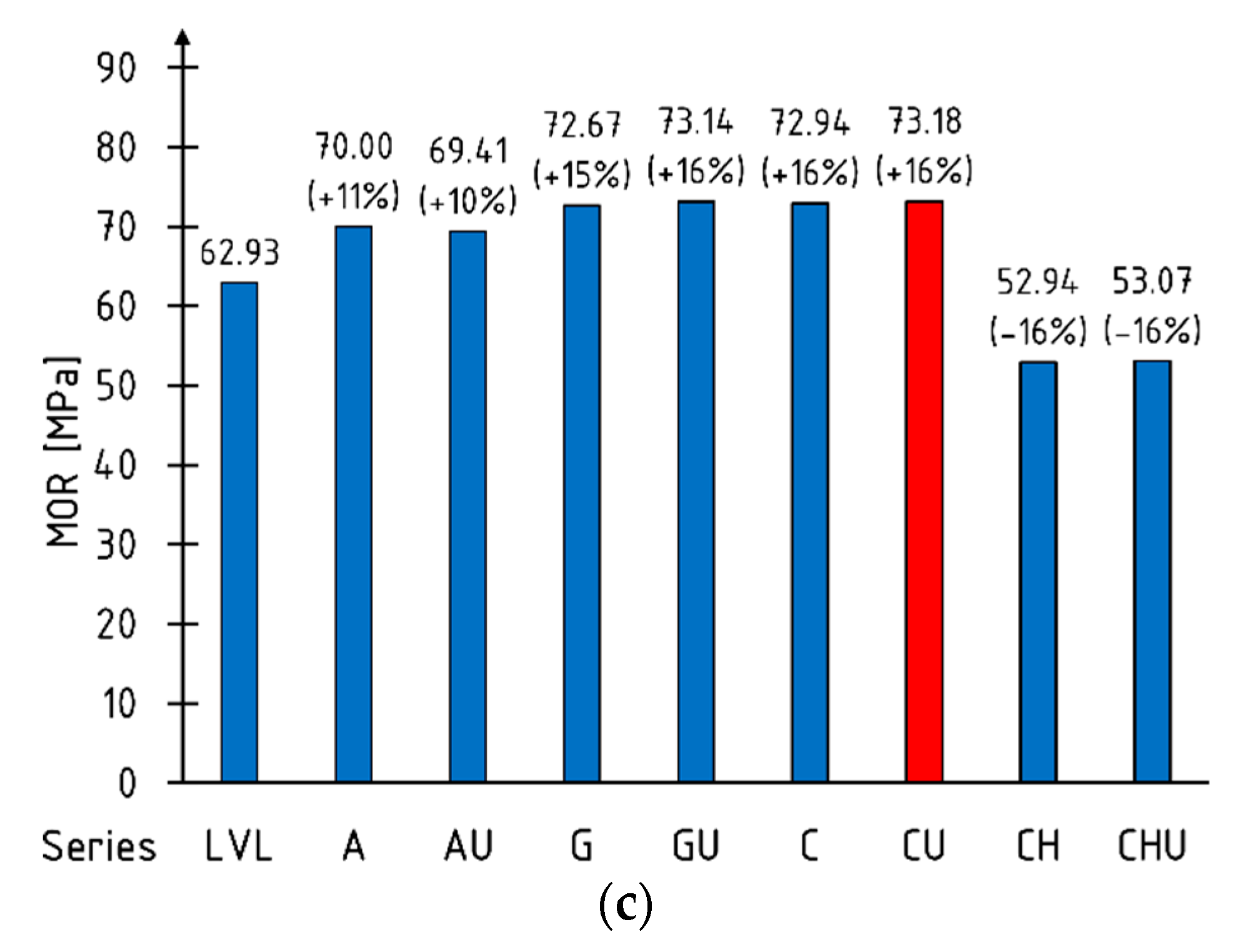
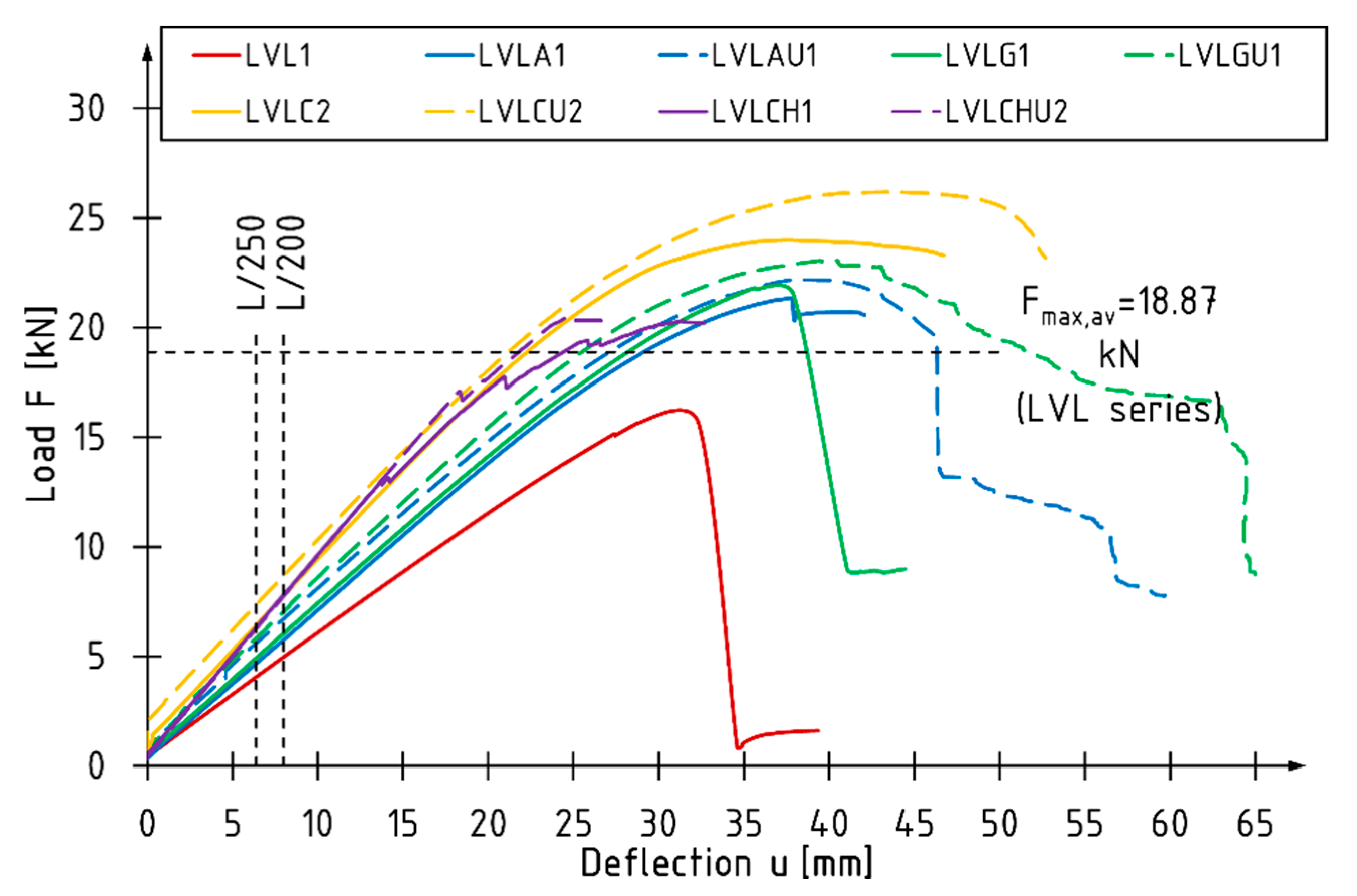
3.1. Bending Strength
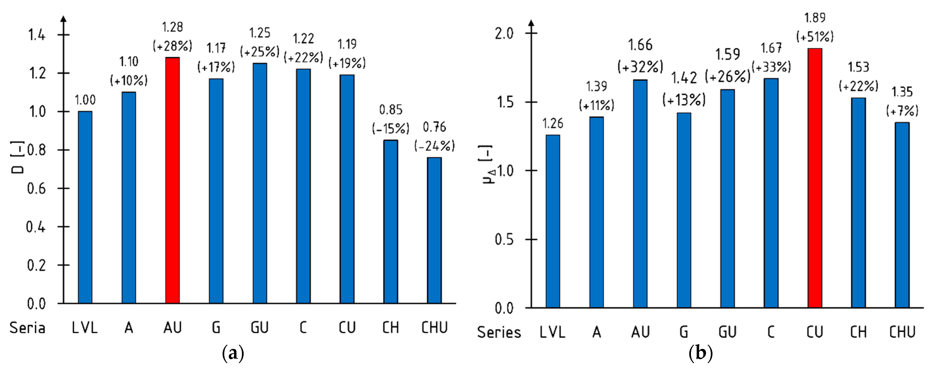
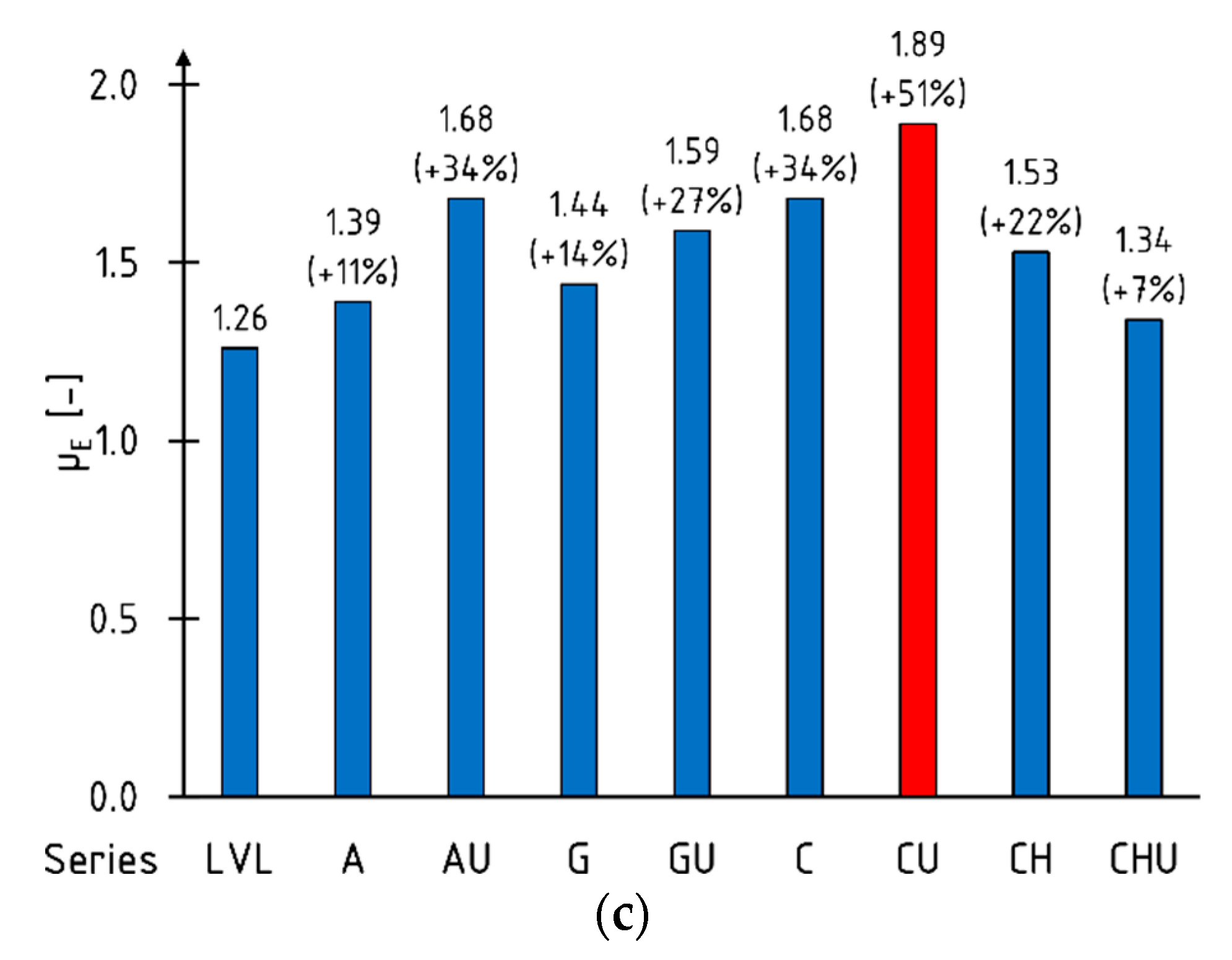
3.2. Ductility
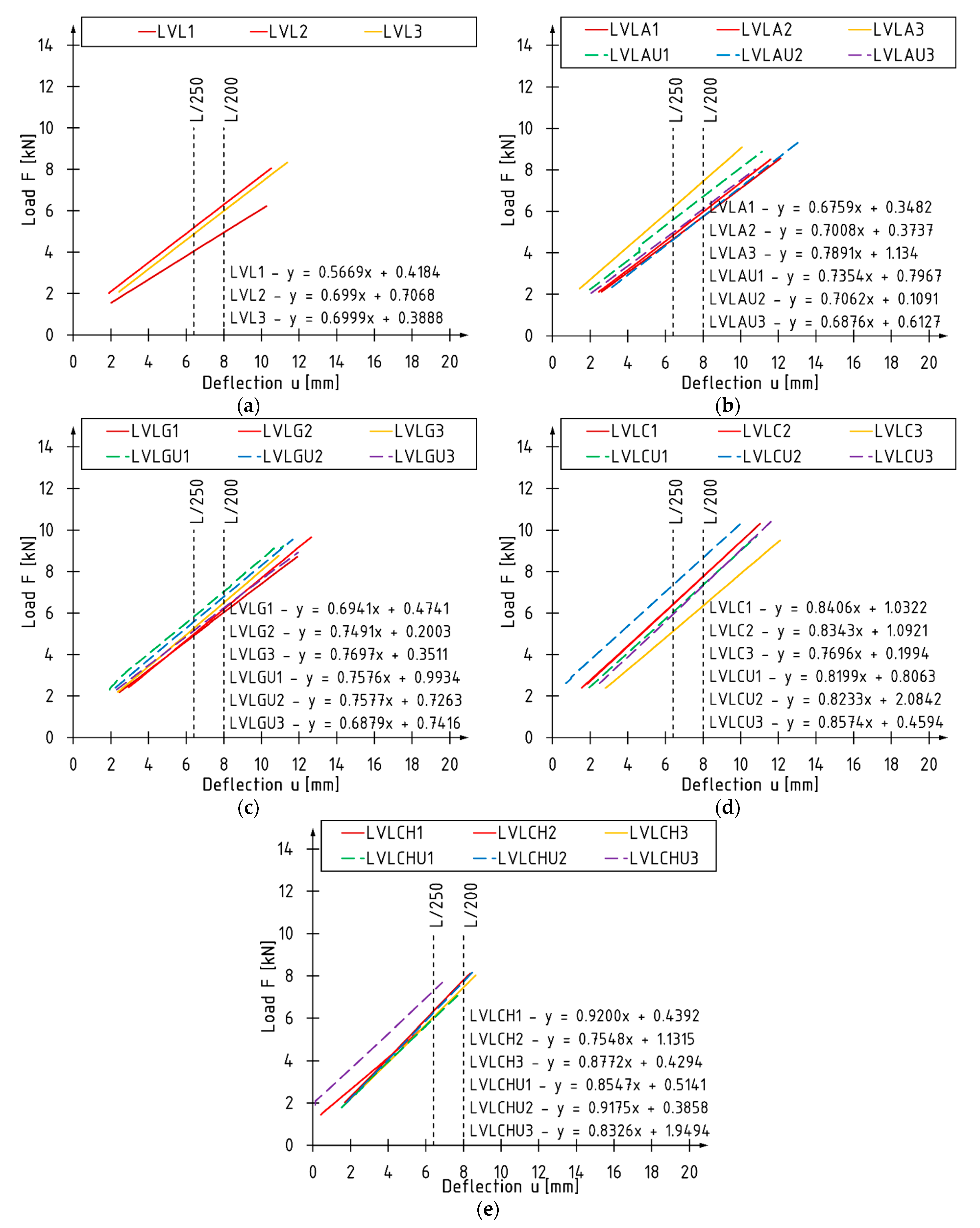
3.3. Stiffness
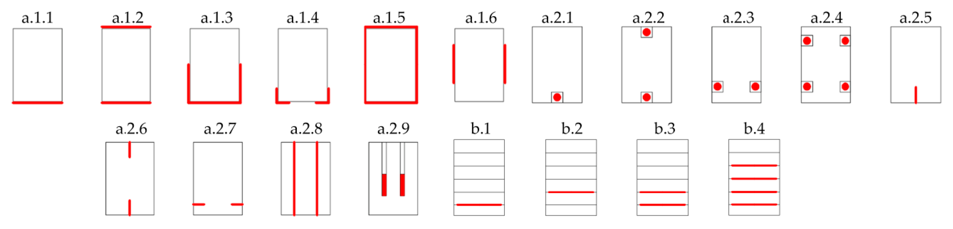
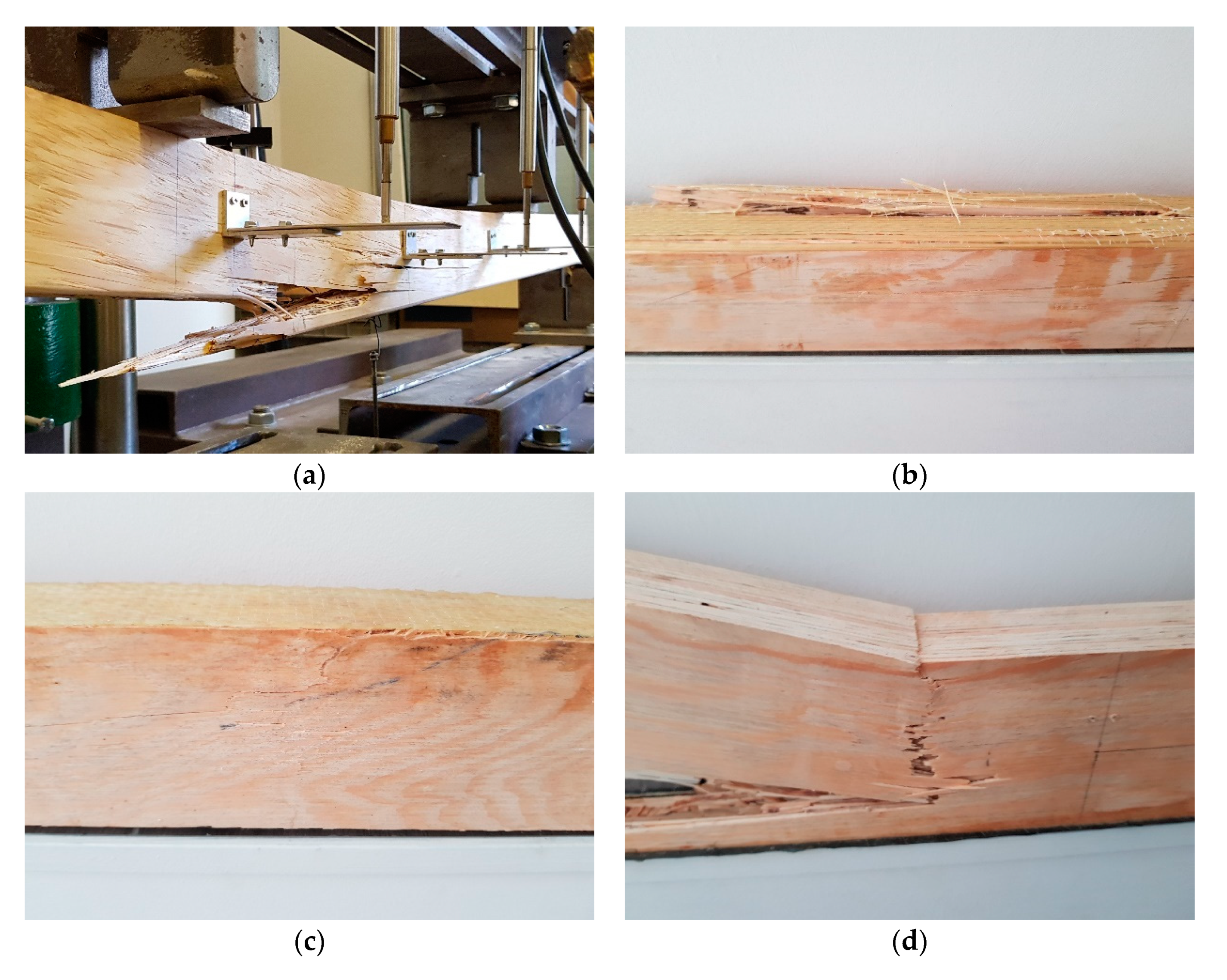
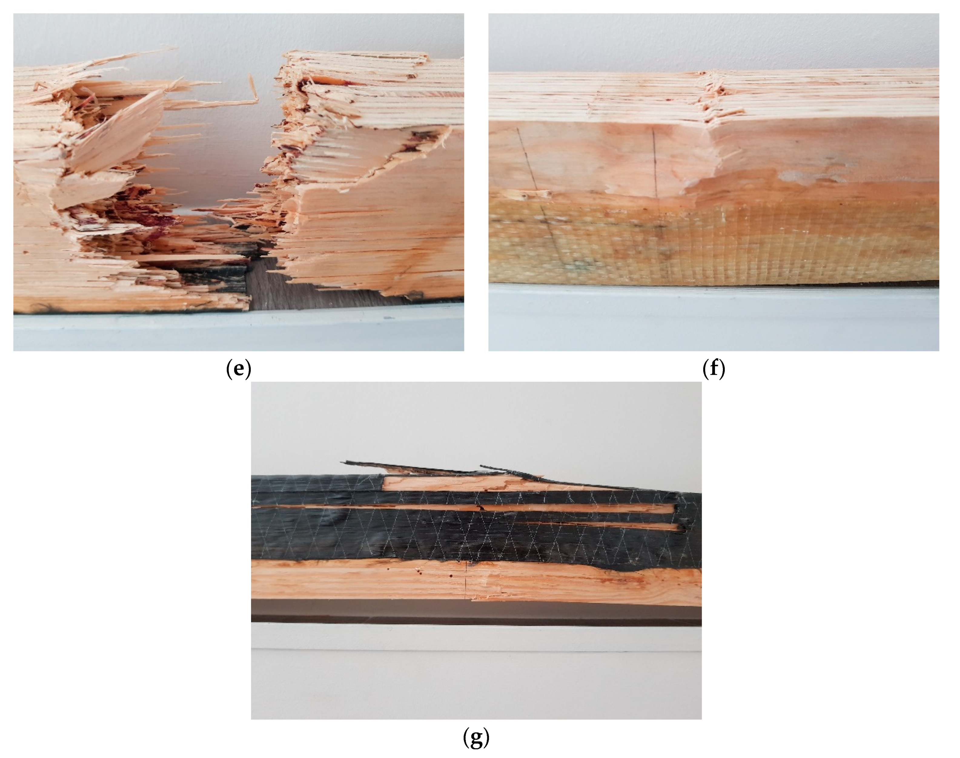
3.4. Failure Modes
- Rupture of composite reinforcement with failure of timber in tension zone (Figure 9b)—typical failure mode for beams strengthened with AFRP and CFRP sheet bonded to the underside;
- Brittle fracture of timber beam in tension zone, with no rupture of composite reinforcement (Figure 9c)—typical failure mode for beams strengthened with GFRP bonded to the underside;
- Shear failure (Figure 9d)—single example recorded for beam strengthened with one layer of CFRP sheet bonded to the underside;
- Sudden rupture of composite fibers which caused splitting the beam—single example (Figure 9e);
- Failure of timber in compression zone (kink-bands), with no rupture of composite reinforcement (Figure 9f)—typical failure for beams strengthened with GFRP sheets in U-configuration;
- Failure of timber in compression zone (kink-bands), with rupture of composite reinforcement (Figure 9g)—typical failure for beams strengthened with AFRP and CFRP sheets in U-configuration.
4. Conclusions
- The time to failure and loading force increases with increasing reinforcement ratio and coverage value of side surface with composite material.
- The higher the modulus of elasticity of composite sheet was, the greater increase of bending stiffness was obtained. The largest percentage increase in the bending stiffness coefficient kg, over 30% in comparison with reference beams, was obtained for the LVLCH and LVLCHU series.
- Generally, the higher the tensile strength of composite sheet was, the greater increase in load bearing capacity was achieved. It is not applicable for composite materials with low value of elongation at rupture, as in the case of UHM CFRP.
- Similar values of the flexural ductility of unreinforced and reinforced beams were obtained when using ductility indices based on plastic deformation—an index based on deflection µΔ and energy absorption µE.
- The ductility, based on comparison of deflection values—index D, of beams strengthened with ultra-high modulus carbon sheets decreased.
- The highest ductility was found in the beams strengthened with HS CFRP sheet which is characterized by high tensile strength, high modulus of elasticity and sufficient elongation at rupture—to withstand elongation of fibers corresponding to the increasing deflection.
Author Contributions
Funding
Institutional Review Board Statement
Informed Consent Statement
Acknowledgments
Conflicts of Interest
References
- Kossakowski, P.G. Influence of anisotropy on the energy release rate G(i) for highly orthotropic materials. J. Theor. Appl. Mech. 2007, 45, 739–752. [Google Scholar]
- Nabati, A.; Ghanbari-Ghazijahani, T.; Valipour, H.R. Innovative flitch sandwich beams with steel core under four-point bending. Eng. Struct. 2021, 233, 111724. [Google Scholar] [CrossRef]
- Chen, S.; Wei, Y.; Peng, D.; Zhao, K.; Hu, Y. Experimental investigation of timber beams strengthened by bamboo scrimber with anchorage structure. Structures 2021, 33, 1–11. [Google Scholar] [CrossRef]
- Micelli, F.; Scialpi, V.; La Tegola, A. Flexural reinforcement of glulam timber beams and joints with carbon fiber-reinforced polymer rods. J. Compos. Constr. 2005, 9, 337–347. [Google Scholar] [CrossRef]
- Raftery, G.M.; Kelly, F. Basalt FRP rods for reinforcement and repair of timber. Compos. Part B Eng. 2015, 70, 9–19. [Google Scholar] [CrossRef]
- Yeboah, D.; Gkantou, M. Investigation of flexural behaviour of structural timber beams strengthened with NSM basalt and glass FRP bars. Structures 2021, 33, 390–405. [Google Scholar] [CrossRef]
- Rescalvo, F.J.; Valverde-Palacios, J.; Suarez, E.; Gallego, A. Experimental Comparison of Different Carbon Fiber Composites in Reinforcement Layouts for Wooden Beams of Historical Buildings. Materials 2017, 10, 1113. [Google Scholar] [CrossRef] [Green Version]
- González-Bravo, C.; Arriaga-Martitegui, F.; Maldonado-Ramos, L.; Díez-Barra, R. Bending reinforcement of timber beams with steel cross sections on the upper face. Mater. Constr. 2010, 60, 123–135. [Google Scholar] [CrossRef]
- Mark, R. Wood-aluminium beams within and beyond the elastic range. Part 1: Rectangular sections. For. Prod. J. 1961, 11, 115–119. [Google Scholar]
- Dziuba, T. The ultimate strength of wooden beams with tension reinforcement. Holzforsch. Holzverwert. 1985, 37, 115–119. [Google Scholar]
- De Luca, V.; Marano, C. A comparison of un-reinforced and reinforced timber glulam with steel bars. Eur. J. Technol. Adv. Eng. Res. 2011, 2, 45–54. [Google Scholar]
- Soriano, J.; Pellis, B.P.; Mascia, N.T. Mechanical performance of glued-laminated timber beams symmetrically reinforced with steel bars. Compos. Struct. 2016, 150, 200–207. [Google Scholar] [CrossRef]
- Nielsen, J.; Ellegaard, P. Moment Capacity of Timber Reinforced with Punched Metal Plate Fasteners. In Proceedings of the 1st RILEM Symposium on Timber Engineering, Stockholm, Sweden, 13–15 September 1999; Boström, L., Ed.; RILEM Publications: Lyon, France, 1999; pp. 129–137. [Google Scholar]
- Corradi, M.; Osofer, A.I.; Borri, A. Repair and Reinforcement of Historic Timber Structures with Stainless Steel—A Review. Metals 2019, 9, 106. [Google Scholar] [CrossRef] [Green Version]
- Pengyi, Z.; Shijie, S.; Chunmei, M. Strengthening mechanical properties of glulam with basalt fiber. Adv. Nat. Sci. 2011, 4, 130–133. [Google Scholar]
- Wdowiak-Postulak, A. Basalt Fiber Reinforcement of Bent Heterogeneous Glued Laminated Beam. Materials 2021, 14, 51. [Google Scholar] [CrossRef] [PubMed]
- Wdowiak-Postulak, A. Natural Fiber as Reinforcement for Vintage Wood. Materials 2020, 13, 4799. [Google Scholar] [CrossRef]
- Wdowiak-Postulak, A.; Brol, J. Ductility of the Tensile Zone in Bent Wooden Beams Strengthened with CFRP Materials. Materials 2020, 13, 5451. [Google Scholar] [CrossRef]
- Burawska, I.; Jachowicz, P.; Zbieć, M.; Grześkiewicz, M. Local reinforcement of naturally defected structural lumber. Ann. Wars. Univ. Life Sci. SGGW. For. Wood Technol. 2014, 87, 25–34. [Google Scholar]
- Theakston, F.H. A feasibility study for strengthening timber beams with fiberglass. Can. Agric. Eng. 1965, 7, 17–19. [Google Scholar]
- Brol, J. Wzmacnianie zginanych belek z drewna klejonego taśmami GARP na etapie produkcji (Strengthening of bent glued laminated (glulam) beams with GARP tapes at the stage of production). Wiadomości Konserw. 2009, 26, 345–353. [Google Scholar]
- Borri, A.; Corradi, M.; Speranzini, E. Bending Tests on Natural Fiber Reinforced Fir Wooden Elements. Adv. Mat. Res. 2013, 778, 537–544. [Google Scholar] [CrossRef]
- Borri, A.; Corradi, M.; Grazini, A.A. A method for flexural reinforcement of old wood beams with CFRP materials. Compos. Part B Eng. 2005, 36, 143–153. [Google Scholar] [CrossRef]
- Brol, J. Wzmacnianie elementów drewnianych taśmami lub matami z włókien węglowych. Zesz. Nauk. Politech. Śląskiej Ser. Bud. 2001, 93, 67–76. [Google Scholar]
- Brol, J. Wzmacnianie zespolonych stropów drewniano-żelbetowych polimerami zbrojonymi włóknami węglowymi. Zesz. Nauk. Politech. Śląskiej Ser. Bud. 2002, 95, 105–113. [Google Scholar]
- Glišović, I.; Stevanović, B.; Todorović, M.; Stevanović, T. Glulam beams externally reinforced with CFRP plates. Wood Res. 2016, 61, 141–154. [Google Scholar]
- Kliger, R.; Johansson, M.; Crocetti, R.; Al.-Emrani, M. Strengthening timber with CFRP or steel plates—short and long-term performance. In Proceedings of the World Conference on Timber Engineering (WCTE08), Miyazaki, Japan, 2–5 June 2008; Engineered Wood Products Association: Tacoma, WA, USA, 2009; pp. 414–421. [Google Scholar]
- Li, Y.-F.; Xie, Y.-M.; Tsai, M.-J. Enhancement of the flexural performance of retrofitted wood beams using CFRP composite sheets. Constr. Build. Mater. 2009, 23, 411–422. [Google Scholar] [CrossRef]
- Nowak, T.P.; Jasieńko, J.; Czepiżak, D. Experimental tests and numerical analysis of historic bent timber elements reinforced with CFRP strips. Constr. Build. Mater. 2013, 40, 197–206. [Google Scholar] [CrossRef]
- Jorissen, A.; Fragiacomo, M. General notes on ductility in timber structures. Eng. Struct. 2011, 33, 2987–2997. [Google Scholar] [CrossRef]
- Schober, K.-U.; Rautenstrauch, K. Post-strengthening of timber structures with CFRPs. Mater. Struct. 2006, 40, 27–35. [Google Scholar] [CrossRef]
- Basterra, L.A.; Balmori, J.A.; Morillas, L.; Acuña, L.; Casado, M. Internal reinforcement of laminated duo beams of low-grade timber with GFRP sheets. Constr. Build. Mater. 2017, 154, 914–920. [Google Scholar] [CrossRef]
- Corradi, M.; Vo, T.P.; Poologanathan, K.; Osofero, A.I. Flexural behaviour of hardwood and softwood beams with mechanically connected GFRP plates. Compos. Struct. 2018, 206, 610–620. [Google Scholar] [CrossRef] [Green Version]
- Gentile, C.; Svecova, D.; Rizkalla, S.H. Timber beams strengthened with GFRP bars: Development and applications. J. Compos. Constr. 2002, 6, 11–20. [Google Scholar] [CrossRef]
- Hernandez, R.; Davalos, J.F.; Sonti, S.S.; Kim, Y.; Moody, R.C. Strength and Stiffness of Reinforced Yellow-Poplar Glued-Laminated Beams; Research Paper FPL-RP-554; Department of Agriculture, Forest Service, Forest Products Laboratory: Madison, WI, USA, 1997. [Google Scholar]
- Raftery, G.M.; Harte, A.M. Low-grade glued laminated timber reinforced with FRP plate. Compos. Part B Eng. 2011, 42, 724–735. [Google Scholar] [CrossRef]
- Raftery, G.M.; Whelan, C.; Harte, A.M. Bonded-in GFRP rods for the repair of glued laminated timber. In Proceeding of the World Conference on Timber Engineering (WCTE12), Auckland, New Zealand, 16–19 July 2012. [Google Scholar]
- Ye, L.; Wang, B.; Shao, P. Experimental and Numerical Analysis of a Reinforced Wood Lap Joint. Materials 2020, 13, 4117. [Google Scholar] [CrossRef]
- Bakalarz, M. Load bearing capacity of laminated veneer lumber beams strengthened with CFRP strips. Arch. Civ. Eng. 2021, 67, 139–155. [Google Scholar]
- Bakalarz, M.M.; Kossakowski, P.G.; Tworzewski, P. Strengthening of Bent LVL Beams with Near-Surface Mounted (NSM) FRP Reinforcement. Materials 2020, 13, 2350. [Google Scholar] [CrossRef] [PubMed]
- Ghazijahani, T.G.; Holloway, D. Composite Timber Beams Strengthened by Steel and CFRP. J. Compos. Constr. 2017, 21, 04016059. [Google Scholar] [CrossRef]
- Shekarchi, M.; Oskouei, A.V.; Raftery, G.M. Flexural behavior of timber beams strengthened with pultruded glass fiber reinforced polymer profiles. Compos. Struct. 2020, 241, 112062. [Google Scholar] [CrossRef]
- Nadir, Y.; Nagarajan, P.; Mohammed, A.; Arif, M.M. Flexural stiffness and strength enhancement of horizontally glued laminated wood beams with GFRP and CFRP composite sheets. Constr. Build. Mater. 2016, 112, 547–555. [Google Scholar] [CrossRef]
- Bhat, J.A. Effect of CFRP-Reinforcement variation on the strength parameters of different timber beams. Mater. Today Proc. 2021, 44, 2785–2791. [Google Scholar] [CrossRef]
- Naaman, A.E.; Jeong, S.M. Structural Ductility of Concrete Beams Prestressed with FRP Tendons. In Proceedings of the 2nd International RILEM Symposium (FRPRXS-2), Non-Metallic (FRP) Reinforcement for Concrete Structures, Ghent, Belgium, 23–25 August 1995; Taerwe, L., Ed.; RILEM: Bagneus, France, 1995; pp. 379–386. [Google Scholar]
- Ali, Y.A.Z. Flexural behavior of FRP strengthened concrete-wood composite beams. Ain Shams Eng. J. 2018, 9, 3419–3424. [Google Scholar] [CrossRef]
- Yusof, A. Bending Behavior of Timber Beams Strengthened Using Fiber Reinforced Polymer Bars and Plates. Ph.D. Thesis, Universiti Teknologi, Johor, Malaysia, 2010. [Google Scholar]
- Ottenhaus, L.-M.; Jockwer, R.; Drimmelen, D.; Crews, K. Designing timber connections for ductility—A review and discussion. Constr. Build. Mater. 2021, 304, 124621. [Google Scholar] [CrossRef]
- Brühl, F.; Kuhlmann, U.; Jorissen, A. Consideration of plasticity within the design of timber structures due to connection ductility. Eng. Struct. 2011, 33, 3007–3017. [Google Scholar] [CrossRef]
- Raftery, G.M.; Harte, A.M. Repair of glulam beams using GFRP rods. Structural Studies, Repairs and Maintenance of Heritage Architecture. WIT Trans. Built Environ. 2009, 109, 417–427. [Google Scholar]
- Borri, A.; Corradi, M. Strengthening of timber beams with high strength steel cords. Compos. Part B Eng. 2011, 42, 1480–1491. [Google Scholar] [CrossRef]
- Corradi, M.; Borri, A. Fir and chestnut timber beams reinforced with GFRP pultruded elements. Compos. Part B Eng. 2007, 38, 172–181. [Google Scholar] [CrossRef]
- Corradi, M.; Borri, A.; Righetti, L.; Speranzini, E. Uncertainty analysis of FRP reinforced timber beams. Compos. Part B Eng. 2017, 113, 174–184. [Google Scholar] [CrossRef]
- Subhani, M.; Globa, A.; Al-Ameri, R.; Moloney, J. Flexural strengthening of LVL beam using CFRP. Constr. Build. Mater. 2017, 150, 480–489. [Google Scholar] [CrossRef]
- Kossakowski, P.; Ordysiński, G. Numeryczne szacowanie sztywności zginanych elementów drewnianych wzmacnianych matami kompozytowymi. Zesz. Nauk. Politech. Rzesz. 2012, 59, 373–380. [Google Scholar]
- Zeszyt Konstrukcyjny STEICO. Fornir Klejony Warstwowo. Available online: https://www.steico.com/fileadmin/steico/content/pdf/Marketing/Polska/Foldery_produktow/LVL/STEICOlvl_pl_i.pdf (accessed on 1 April 2021).
- Technical Data Sheets of Composite Materials. Available online: http://www.sp-reinforcement.pl/pl-PL (accessed on 1 April 2021).
- Polski Komitet Normalizacyjny. Konstrukcje Drewniane—Drewno Konstrukcyjne Lite i Klejone Warstwowo. Oznaczanie Niektórych Właściwości Mechanicznych; PN-EN 408+A1:2012; Polski Komitet Normalizacyjny: Warszawa, Poland, 2012. [Google Scholar]
- Polski Komitet Normalizacyjny. Konstrukcje Drewniane. Fornir Klejony Warstwowo (LVL). Wymagania; PN-EN 14374:2005; Polski Komitet Normalizacyjny: Warszawa, Poland, 2005. [Google Scholar]
- Rudziński, L. Konstrukcje Drewniane. Naprawy, Wzmocnienia, Przykłady Obliczeń; Wydawnictwo Politechniki Świętokrzyskiej: Kielce, Poland, 2010. [Google Scholar]
- Masłowski, E.; Spiżewska, D. Wzmacnianie Konstrukcji Budowlanych; Wydawnictwo Arkady: Warszawa, Poland, 2000. [Google Scholar]
- Grace, N.F.; Soliman, A.K.; Abdel-Sayed, G.; Saleh, K.R. Behaviour and Ductility of Simple and Continuous FRP Reinforced Beams. J. Compos. Constr. 1998, 2, 186–194. [Google Scholar] [CrossRef]
- Mirmiran, A.; Shahawy, M.; Samaan, M. Strength and Ductility of Hybrid FRP-Concrete Beam-Columns. J. Struct. Eng. 1999, 125, 1085–1093. [Google Scholar] [CrossRef]
- Park, R. Evaluation of ductility of structures and structural assemblages for laboratory testing. Bull. N. Z. Soc. Earthq. Eng. 1989, 22, 155–166. [Google Scholar] [CrossRef]
- Wang, H.; Belarbi, A. Flexural behavior of fiber-reinforced-concrete beams reinforced with FRP rebars. ACI Struct. J. 2005, 51, 895–914. [Google Scholar]
- Tomasi, R.; Parisi, M.A.; Piazza, M. Ductile design of glued-laminated timber beams. Pract. Period. Struct. Des. 2009, 14, 113–122. [Google Scholar] [CrossRef]
- Polski Komitet Normalizacyjny. Projektowanie Konstrukcji Drewnianych. Część 1-1: Postanowienia Ogólne. Reguły Ogólne i Reguły Dotyczące Budynków PN-EN 1995-1-1:2010. Eurokod 5; Polski Komitet Normalizacyjny: Warszawa, Poland, 2010. [Google Scholar]


| Parameter | Value |
|---|---|
| Bending strength (edgewise condition) fm,0,edge [MPa] | 44 |
| Bending strength (flatwise condition) fm,0,flat [MPa] | 50 |
| Tensile strength parallel to the grain ft,0 [MPa] | 36 |
| Tensile strength perpendicular to the grain ft,90,edge [MPa] | 0.9 |
| Compression strength parallel to the grain fc,0 [MPa] | 40 |
| Compression strength perpendicular to the grain (edgewise condition) fc,90,edge [MPa] | 7.5 |
| Shear strength parallel to the grain fv,0,edge [MPa] | 4.6 |
| Modulus of elasticity in bending E [GPa] | 14 |
| Shear modulus G [MPa] | 600 |
| Density ρd [kg/m3] | 550 |
| Parameter | AFRP Sheet | GFRP Sheet | HS CFRP Sheet | UHM CFRP Sheet |
|---|---|---|---|---|
| Modulus of elasticity Ef [GPa] | ≥120 | ≥73 | ≥265 | ≥640 |
| Tensile strength ft,f [MPa] | ≥2900 | ≥3400 | ≥5100 | ≥2600 |
| Fiber mass mf [kg/m2] | 0.290 | 0.800 | 0.600 | 0.400 |
| Sheet mass ms [kg/m2] | 0.320 | 0.880 | 0.630 | 0.430 |
| Density ρf [kg/m3] | 1450 | 2600 | 1800 | 2120 |
| Elongation at rupture εf [%] | 2.5 | 4.5 | 1.7–1.9 | 0.4 |
| Design thickness tf [mm] | 0.200 | 0.308 | 0.333 | 0.189 |
| Parameter | Value |
|---|---|
| Modulus of elasticity Ek [MPa] | ≥3200 |
| Density ρk [kg/m3] | 1200–1300 |
| Compressive strength fc,k [MPa] | ≥100 |
| Series | LVL | LVLA | LVLAU | LVLG | LVLGU | LVLC | LVLCU | LVLCH | LVLCHU |
|---|---|---|---|---|---|---|---|---|---|
| Moisture content [%] | 14.8 | 14.0 | 14.5 | 14.1 | 14.5 | 14.3 | 13.6 | 15.1 | 13.7 |
| Slope of Linear Function a [kN/mm] | x [kN/mm] | s [kN/mm] | Vs [%] | R [kN/mm] |
|---|---|---|---|---|
| L1: 0.5669; L2: 0.699; L3: 0.6999 | 0.655 | 0.077 | 11.68 | 0.133 |
| A1: 0.6759; A2: 0.7008; A3: 0.7891 | 0.722 (+10%) | 0.059 | 8.24 | 0.113 |
| AU1: 0.7354; AU2: 0.7062; AU3: 0.6876 | 0.710 (+8%) | 0.024 | 3.40 | 0.048 |
| G1: 0.6941; G2: 0.7491; G3: 0.7697 | 0.738 (+13%) | 0.039 | 5.30 | 0.076 |
| GU1: 0.7576; GU2: 0.7577; GU3: 0.6879 | 0.734 (+12%) | 0.040 | 5.48 | 0.070 |
| C1: 0.8406; C2: 0.8343; C3: 0.7696 | 0.815 (+24%) | 0.039 | 4.82 | 0.071 |
| C1: 0.8199; CU2: 0.8233; CU3: 0.8574 | 0.834 (+27%) | 0.021 | 2.49 | 0.038 |
| CH1: 0.9200; CH2: 0.7548; CH3: 0.8772 | 0.851 (+30%) | 0.086 | 10.08 | 0.165 |
| CHU1: 0.8547; CHU2: 0.9175; CHU3: 0.8326 | 0.868 (+33%) | 0.044 | 5.07 | 0.085 |
Publisher’s Note: MDPI stays neutral with regard to jurisdictional claims in published maps and institutional affiliations. |
© 2022 by the authors. Licensee MDPI, Basel, Switzerland. This article is an open access article distributed under the terms and conditions of the Creative Commons Attribution (CC BY) license (https://creativecommons.org/licenses/by/4.0/).
Share and Cite
Bakalarz, M.M.; Kossakowski, P.G. Ductility and Stiffness of Laminated Veneer Lumber Beams Strengthened with Fibrous Composites. Fibers 2022, 10, 21. https://doi.org/10.3390/fib10020021
Bakalarz MM, Kossakowski PG. Ductility and Stiffness of Laminated Veneer Lumber Beams Strengthened with Fibrous Composites. Fibers. 2022; 10(2):21. https://doi.org/10.3390/fib10020021
Chicago/Turabian StyleBakalarz, Michał Marcin, and Paweł Grzegorz Kossakowski. 2022. "Ductility and Stiffness of Laminated Veneer Lumber Beams Strengthened with Fibrous Composites" Fibers 10, no. 2: 21. https://doi.org/10.3390/fib10020021