Review

Bond between Fibre-Reinforced Polymer Tubes and Sea Water Sea Sand Concrete: Mechanisms and Effective Parameters: Critical Overview and Discussion

1
College of Engineering, IT & Environment, Charles Darwin University, Darwin 0815, Australia
2
School of Mechanical and Mining Engineering, The University of Queensland, Queensland 4072, Australia
*
Author to whom correspondence should be addressed.
Fibers 2022, 10(1), 8; https://doi.org/10.3390/fib10010008
Submission received: 19 December 2021 / Revised: 5 January 2022 / Accepted: 10 January 2022 / Published: 14 January 2022

Abstract

:
Using fibre-reinforced polymers (FRP) in construction avoids corrosion issues associated with the use of traditional steel reinforcement, while seawater and sea sand concrete (SWSSC) reduces environmental issues and resource shortages caused by the production of traditional concrete. The paper gives an overview of the current research on the bond performance between FRP tube and concrete with particular focus on SWSSC. The review follows a thematic broad-to-narrow approach. It reflects on the current research around the significance and application of FRP and SWSSC and discusses important issues around the bond strength and cyclic behaviour of tubular composites. A review of recent studies of bond strength between FRP and concrete and steel and concrete under static or cyclic loading using pushout tests is presented. In addition, the influence of different parameters on the pushout test results are summarised. Finally, recommendations for future studies are proposed.

Graphical Abstract

1. Introduction

Fibre-reinforced polymer (FRP) concrete composites have found increasing application in the civil engineering and construction sector over the past years [1,2,3]. This is mostly attributed to their excellent mechanical properties, such as high strength-to-weight ratio and stiffness [4,5,6], durability [7,8,9] and simple manufacturing and installation processes [8,10]. Furthermore, its high corrosion resistance makes it a highly suitable alternative to steel in corrosive environments [10,11,12]. FRP concrete composites are typically manufactured to form either FRP wraps/tubes to externally confine the concrete [2,13,14] or as FRP reinforcement bars [15,16] similar to traditionally reinforced concrete [12]. FRP tubular composites have the benefit of enhanced compressive strength and ductility compared to an identical traditionally reinforced concrete section [2,17,18]. Additionally, the FRP confinement protects the concrete core against environmental exposure, thereby increasing durability especially in aggressive environmental conditions whilst providing structural reinforcement through permanent lightweight formwork [12,19]. Therefore, FRP and concrete tubular composites find popular application in marine environments [1,17], such as bridge piers or offshore drilling platforms [8,20], or in seismic environments [3].
Another advantage of FRP encasements is their high corrosion resistance which, contrary to traditional concrete, make them suitable for use in conjunction with seawater and sea sand concrete (SWSSC) [10,21,22]. Due to its high chloride content, SWSSC causes durability and corrosion issues when applied in traditional steel reinforcement environments [20,23]. However, in conjunction with FRP it can form a more sustainable and attractive alternative to traditional concrete tubular composites [2,12]. The production of traditional concrete creates some concerns regarding the availability of limited natural resources and environmental disturbances associated with the extraction of fresh water and river sand [10,20]. Replacing these resources with the more abundant resources of seawater and sea sand can be a suitable solution in avoiding resource shortages and reducing environmental impacts [2,20,24,25,26,27,28], especially since the demand for concrete is increasing worldwide [10,12]. Furthermore, in SWSSC geopolymers such as slag and fly ash can replace Portland cement, which is a major contributor to global CO2 emissions in traditional concrete [12]. Despite their different production processes, SWSSC was found to possess similar mechanical properties to traditional concrete [8], which is a significant advantage in structural applications.
In recent years multiple studies have been conducted to investigate the mechanical properties and durability of SWSSC filled FRP tubes under static load [2,8,18,20,29,30,31] and the axial compressive behaviour and strength of concrete filled FRP tubes under both static and cyclic loading [3,32,33,34]. However, very few studies were conducted on the bond slip behaviour of FRP tubular composites. Table 1 and Table 2 summarise the research plan of previous studies on the short-term and long-term structural performance of SWSSC filled FRP tubes.
Good bond strength along the tube and concrete interface is significant to achieving full composite action between the FRP tube and the concrete core [12,46,47]. Without adequate bond strength, slip between the concrete and the FRP may occur and full load transfer between the FRP tube and the concrete core can no longer be guaranteed [17,48,49]. It is therefore significant to fully understand the interfacial bond mechanisms between the FRP tube and the concrete core to ensure full composite action of the member and prevent premature bond failure under static or cyclic loads.
This paper provides an overview of the current research on fibre-reinforced polymer (FRP) and seawater and sea sand concrete (SWSSC) composites with particular focus on their bond behaviour and bond strength under static and cyclic loading. It aims to improve the understanding of the bond strength and behaviour of FRP-concrete tubes and in particular the FRP-SWSSC tube, with the intent to further the application of FRP SWSSC composites in the construction industry as a corrosion resistant and environmentally friendly alternative to traditionally steel reinforced concrete.
The review follows a thematic broad-to-narrow approach. Section 2 reflects on the current research around the significance and application of FRP and SWSSC and discusses important issues around the bond strength of tubular composites. Section 3 presents a review of recent studies relevant to this paper. Due to the limited research conducted on FRP and SWSSC tubular composites under pushout-tests, this review includes studies on FRP or steel and traditional concrete composites for comparison. Section 4 examines the results obtained by studies presented in Section 3, with particular focus on their load–displacement behaviour. Section 5 analyses the influence of different parameters on the results presented in Section 4. Finally, Section 6 presents suggestions for further studies.

2. Significance of FRP and SWSSC and Their Bond Strength in Construction

2.1. Fibre-Reinforced Polymers

Due to their favourable mechanical properties, such as high strength-to-weight ratio, high stiffness and high corrosion resistance [10,28,32], FRP composites have attracted increasing attention in the research and construction sector in recent years [3,11,50]. These properties have made them popular for a wide range of application particularly in the marine engineering sector, such as for example in bridge piers, high-rise buildings and drilling platforms [1,8,20]. Especially in corrosive environments, FRP composites form an attractive alternative to traditional steel reinforcement, owing to their high corrosion resistance [10,51,52,53]. Furthermore, fibres can be oriented [54] to give desirable mechanical properties in circumferential and longitudinal directions in FRP composites [2,55]. It is worth mentioning that vulnerability to elevated temperatures [56,57,58], low shear strength and ductility [1] are some of the FRP drawbacks that hinder their wide usage in specific applications.
A popular application of FRP concrete composites is in the form of tubular columns [18]. These tubular columns have the advantage of higher compressive and bending strength compared to an identical reinforced concrete section, as the confinement effect of the tube delays buckling failure of the columns [2,17,18]. The FRP tube serves as permanent formwork, which not only provides structural reinforcement, but also increases the durability of the column, by covering the concrete against environmental exposure and delaying deterioration caused by exposure to the elements [17,19]. Tubular FRP concrete columns therefore have the economic advantage of allowing comparatively smaller and more lightweight sections and eliminating the need for additional formwork [17,19]. The tubular confinement also causes an increase in stiffness and ductility, which has significant advantages in seismic applications [19].
Due to their advantageous properties, concrete filled FRP columns are being increasingly used in seismic environments, as either refurbishment of existing columns or for new columns, or in marine environments for example as poles or bride columns [3].

2.2. Seawater and Sea sand Concrete

In SWSSC, seawater and sea sand replace fresh water and river sand to improve the sustainability of the concrete. Using seawater and sea sand preserves the limited freshwater and river sand resources [28] and reduces environmental impacts caused by the extraction of said resources [2,10,12]. Furthermore, CO2 emissions can be significantly reduced by replacing Portland cement with geopolymers such as slag and fly ash [7,20]. The production of traditional concrete and particularly Portland cement is a significant contributor to global greenhouse gas emissions [59,60]. Considering current global climate debates and continuing population growth related to an inevitable increase in demand for concrete [20,61], it is of global significance to find a more sustainable alternative to replace traditional concrete in the building and construction sector.
Research into the compressive behaviour and workability of SWSSC has found that SWSSC possesses similar mechanical properties to traditional concrete [2,10,62], which is a significant advantage in terms of replacing traditional concrete with SWSSC in construction. Furthermore, geopolymers (slag and fly ash) used in the SWSSC mix have been shown to reduce shrinkage cracking, which is problematic in traditional concrete in aggressive environments [8].
There is concern about the use of SWSSC, which is mostly related to its application in conjunction with traditional steel reinforcement, as the high chloride content in the SWSSC mix causes durability problems associated with steel corrosion [8,23]. To avoid this issue, research suggests the use of FRP instead of traditional steel, which has the advantage of high corrosion resistance [23,44]. Figure 1 schematically shows some of the current typical applications of FRP–SWSSC hybrid structures.

2.3. Bond Strength in Composite Materials

Bond strength defines the interfacial adhesion between two materials [47]. This adhesion causes both materials to experience identical strain under loading and thereby allows them to act as a composite material [47]. Therefore, good bond strength is essential to facilitate stress transfer between the FRP and concrete to achieve the desired composite action between the two materials [12,17].
This phenomenon is of particular significance in construction. When FRP tubular composites are used as columns, connection details are often designed to transfer loads from a superior element directly to the outer tube. Adequate force transfer between the tube and the filling is therefore required to ensure full composite action. This force transfer occurs through the natural bond between the outer tube and inner concrete core and can be enhanced by the use of shear connectors [17,46].
Johansson and Gylltoft [63] found that the bond strength only influences the mechanical properties of the composite if the load is only applied to one part of the composite (for example the concrete core). If load is shared equally between the tube and the core, the bond strength has no influence on the performance of the composite [63]. This appears logical, as in the latter case the load is already shared between the two components and bond strength is not required to be engaged to facilitate load sharing to enable composite action. However, Aly et al. [46] note that ensuring simultaneous loading of the tube and core is often challenging to accomplish in practice. Therefore, a good understanding of the bond behaviour and bond strength is required to ensure full composite action and adequate performance and prevent premature bond failure under static and dynamic loads.

2.4. Cyclic Behaviour and Bond Strength

Knowledge of the bond behaviour under cyclic loading is especially relevant for application in seismic areas [64]. Previous research on tubular concrete composites has shown that confining concrete in circular tubes leads to a significant increase in strength, ductility and cyclic load carrying capacity compared to unconfined concrete [20], thereby increasing its suitability for seismic applications. Therefore, FRP is often used as confinement material for existing or newly constructed concrete columns or other tubular members [64], especially in seismic applications [3].
Furthermore, even outside of seismic zones, the common applications of FRP concrete composite columns inevitably subject the member to dynamic loading conditions, such as pile driving loads, tidal influences or moving traffic loads on bridge piers, throughout their lifetime. Under cyclic load condition the composite element is subjected to continuously changing loading and unloading cycles [47]. The interface bond is therefore subjected to a rapid change in load, which causes substantial accumulated damage to the bonding surface [65]. Research has shown that this can lead to a significant reduction in bond strength for steel and concrete composites [46,47]. Furthermore, studies conducted on the bond behaviour of concrete reinforced with FRP bars have shown that cyclic load can cause significant bond deterioration, increase in slip and reduction in energy dissipation compared to an identical monotonically loaded sample [66,67,68].
It is therefore obvious that it is significant to fully understand the effects of cyclic load on the bond performance of concrete filled FRP tubes. However, no comprehensive studies have been conducted to date to investigate such behaviour in concrete filled FRP tubes under cyclic loading.

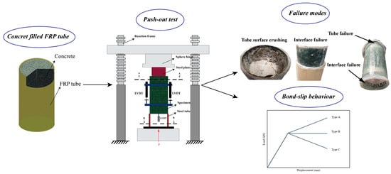
3. Overview of Recent Bond-Slip Studies under Pushout Loads

Table 3 shows a summary of some of the most relevant studies reviewed to investigate the bond performance in pushout tests. It is worth mentioning that, due to limited studies involving FRP and SWSSC, pushout test studies of concrete-filled steel tube and concrete filled FRP tubes were also presented in Table 3 for comparison.
The studies are summarised with respect to their testing methodology to evaluate different testing methods that have been proven to be reliable and functional for the given purpose. As seen in Table 3, all studies investigated the bond strength between concrete and FRP or steel composites using a pushout test. It can be seen that very few studies investigating the bond strength of FRP and concrete composites are available and that none of these studies have conducted pushout tests under cyclic load, which must be considered for future studies.

3.1. Materials and Samples

Bazli et al. [12,44] conducted studies on filament wound CFRP, GFRP and BFRP tubes. Other studies used pultruded [17] or filament wound [19] FRP tubes of varying thicknesses. Multiple studies were performed with either stainless steel or carbon steel tubes, typically using cold-formed steel of Grade 350 or 450 [46,69,70]. It should be noted that multiple other studies conducting pushout tests of tubular steel concrete composites have been performed in the past (for example by Liu et al. [48] using recycled aggregate concrete and by Chen et al. [49] using stainless steel CHS tubes), with a similar set-up to the one used by Tao et al. [70]. These are slightly less relevant to this paper, but still offer interesting insight into the bond slip behaviour of confined concrete tubes. Different concrete types were used, such as traditional concrete by [17,19,46,69,70], recycled aggregate concrete by [47] and SWSSC by [12,44].
Sample size was generally small with diameters ranging between 130 mm and 400 mm and sample height between 200 mm and 450 mm [12,17,19,44,46].

3.2. Type of Test

Most studies conducted pushout tests only under monotonic loads [12,17,19,44,69,70]. Solely Aly et al. [46] and Xue et al. [47] investigated pushout tests under cyclic loading. Both studies conducted a baseline compression test for each sample to obtain a load–displacement diagram and ultimate bond strength under monotonic load, followed by a single or multiple cyclic pushout test. Aly et al. [46] used a load-controlled cyclic loading pattern as shown in Figure 2a, which slowly increases the applied load by a percentage of the ultimate load obtained from the static pushout test. Xue et al. [47] applied reversed cyclic loads under controlled displacements to the specimen (refer Figure 2b). These displacements were predefined and based on the load–displacement curve obtained under static loading. This approach is similar to the typical test set-up for FRP concrete tubes subjected to cyclic compression tests [32,33,71].

3.3. Parameters

Varying parameters were chosen to investigate the difference in bond slip behaviour under those parameters when subjected to pushout loading. A common parameter chosen by [12,17,47,69,70] was the effect of varying tube geometry, such as diameter and thickness and tube material on the results. The authors of [19,46,69,70] also investigated various concrete compositions as an additional parameter. Some results were also obtained using different types of shear connectors to enhance bond strength [17,70]. Another parameter adopted is the effect of cyclic load on the bond strength, which was studied by [46,47].

3.4. Test Set-Up

Figure 3 shows the two most common pushout test set-ups used in the literature. Bazli et al. [12] prepared the samples with a small airgap at the bottom and used a steel plate with a slightly smaller diameter than the tube used to push the concrete through the sample. This test set-up is shown as Type A in Figure 3 and was also used by [44,46,69]. Type B was used by [17,19,70]. The tube is lined up on another tube or steel support of diameter slightly larger than the inner tube diameter. The concrete core is then pushed into the support tube underneath the sample.

4. Discussion on Findings from Previous Pushout Test Results

4.1. Bond Mechanisms

Yuan and Hadi [72,73] found that, primarily, three different bond mechanisms constitute the bond strength of FRP and concrete composites:
(i) Mechanical Interlocking, which occurs due to variations in the surface structure of the material. In FRP tubes this effect is considered insignificant due to the inherent smoothness of the material; (ii) Chemical adhesion between FRP and concrete, and (iii) Frictional resistance caused by the roughness of the FRP along the concrete interface.
By comparing the load–displacement curves of the first pushout cycle to subsequent cycles, Bazli et al. [12] showed that, prior to the first slip, bond strength is determined by chemical adhesion between concrete and tube and frictional resistance. Once the chemical bond is broken during the initial slip, bond resistance is only caused by friction along the interface between tube and concrete. This conclusion was based on the observation that the maximum axial force and bond stress did not change significantly between the cycles, apart from a small initial spike in bond strength during the first cycle caused by the additional presence of a chemical bond between the tube and the concrete. Bazli et al. [44] also reported that, during the initial phase of the pushout test prior to reaching the ultimate bond strength, the frictional resistance is determined by the static friction coefficient. Once ultimate bond strength is reached and a significant slip occurs, the kinetic friction coefficient is active.
Bazli et al. [12] conducted an investigation into the frictional resistance of the FRP tubes prior to and after the pushout tests were conducted. By measuring the surface roughness of the same sample before casting and after each push cycle, the study found that the roughness of the inner tube surface remains essentially unchanged after bond slip. Bazli et al. [12] concluded that this means that the frictional coefficient remains relatively constant irrespective of the number of times the pushout test is repeated. The frictional factor was found to be almost the same for all tubes with values between 0.17 and 0.26 and the frictional resistance was shown to vary with the confining pressure. Bazli et al. [12] also showed that the chemical bond was almost identical for all filament wound samples tested with a value of around 0.1 MPa. Furthermore, the chemical resistance was found to have minor influence on the bond strength.
The same bond mechanisms as reported above were found to be present in concrete filled steel tubes [46,69]. Similar to the FRP tubular composites, the smoothness of the steel surface causes minimal mechanical interlocking resistance and is therefore negligible. As the chemical bond breaks after the initial slip regardless of the material, frictional resistance along the interface was found to be the main contributor to bond strength after the initial slip for steel columns. The chemical adhesion was found to contribute to less than 30% of the overall bond strength [49,69]. Aly et al. [46] note that the ultimate bond strength based on the chemical and frictional resistance should not be used for design purposes, as the chemical bond is inherently unstable and diminishes after the initial slip.
It can therefore be concluded that, provided the inner interface of the tube is reasonably smooth, frictional resistance between the inner tube surface and outer core surface is the major factor in determining the interfacial bond strength of a tubular composite.

4.2. Failure Modes

In their study of bond strength of SWSSC filled FRP tubes, three failure modes were observed by Bazli et al. [12] in their pushout test: concrete slip; tube failure before slip occurred; and a combination of both (slip-initiated tube failure). These failure modes are shown in Figure 4.
Bond slip interface failure occurred for all samples with mixed fibre orientation, as compressive strength exceeded bond strength for said samples [12].
All Basalt FRP (BFRP) samples with 89° fibre orientation experienced premature tube failure due to their comparatively low compressive strength. Tube failure was also observed for both Carbon FRP (CFRP) samples, although this failure mode occurred simultaneously to bond slip failure for the 2 mm sample. Interestingly all except one Glass FRP (GFRP) sample exhibited bond slip failure rather than tube failure, despite their similar compressive strength to the carbon fibre samples. This indicates that GFRP tubes possess inherently lower bond strength than CFRP tubes, which was also reflected by the pushout test results. These results can give some significant insights on the expected failure modes during pushout tests. It should be noted that, if the samples fail in tube compressive failure mode, the recorded bond stress might lie well below the actual bond strength and the test results may not provide reliable or useful information [12].

4.3. Bond Strength Test Results

The bond strength was generally obtained from the maximum pushout force, by dividing the force recorded at ultimate slip by the interface area. Although the variation in surface irregularities causes a variation in bond strength along the interface, the bond stress distribution may be considered uniform in order to determine the bond strength of the composites [12,17,46].
In the study of Bazli et al. [12] it was shown that BFRP has the lowest bond strength with average slip initiation forces ranging from 10.65 kN to 40.02 kN and average bond strengths of 0.26 MPa to 0.99 MPa for the different D/t ratios and fibre orientations. The lowest and highest values correspond to measurements taken for the 2 mm mixed fibre orientation tube and the 4 mm 89° fibre orientation tubes, respectively. Intermediate values of 13.55 kN and 0.35 MPa and 28 kN and 0.82 MPa were obtained for the 2 mm 89° fibre orientation and the 4 mm mixed fibre orientation tubes, respectively. However, it should be noted that, since tube failure occurred prior to bond slip for both 89° fibre orientation tubes, the actual bond strength likely exceeds the above-mentioned bond stress measured at failure.
It was also reported that CFRP possessed the highest bond strengths, with average bond strength and slip initiation forces ranging from 0.64 MPa and 23.6 kN for the 2 mm mixed fibre orientation tube to 2.44 MPa and 108 kN for the 4 mm 89° fibre orientation. The results for the 2 mm 89° fibre orientation tube and the 4 mm mixed fibre orientation tube were 40.7 kN and 1.12 MPa and 57.1 kN and 1.71 MPa, respectively. Similar to the BFRP samples with 89° fibre orientation, it is expected that the real bond strength of the CFRP 89° fibre orientation tubes lies somewhat above the bond stress measured at failure, as premature tube failure occurred.
Finally, they showed that, for GFRP, the minimum and maximum values for bond strength and slip load only slightly exceeded the values obtained for their corresponding BFRP samples with 12.1 kN and 0.29 MPa for the 2 mm mixed fibre orientation tube and 45.9 kN and 1.21 MPa for the 4 mm tube with fibres orientated in 89 deg. However, the values for bond strength and slip load measured for the 4 mm mixed orientation tube and the 2 mm 89° orientation tubes were located more in between the Basalt and Carbon FRP results rather than close to the Basalt FRP values with 0.65 MPa and 27.7 kN and 1.18 MPa and 38.8 kN, respectively.
The bond strength results obtained by Li et al. [19] compare well to the results obtained by Bazli et al. [12] for their GFRP tubes of similar diameter and concrete strength. For their 50 MPa sample of 101 mm diameter and 6 mm thickness with fibre orientation in 54° from the longitudinal axial, Li et al. [19] obtained a bond strength of 0.62 MPa. The bond strength of the mixed fibre orientation 4 mm GFRP sample was 0.65 MPa, suggesting a good fit of both experimental results.
Ali et al. [17] conducted pushout tests of pultruded GFRP tubes with larger diameters and thickness than the pultruded ones used by Bazli et al. [12] and obtained very small bond strengths of 0.03 MPa for their 305 mm diameter sample and 0.025 MPa for their 406 mm sample. These are significantly lower than the bond strengths obtained by Bazli et al. [12] for their GFRP tubes. Since obviously using thicker tube will not reduce the bond strength, it can be concluded that a larger diameter reduces the bond strength. However, although both tubes were manufactured using pultruded process, the effect of the tube surface roughness could be also considered as an effective factor when comparing two studies.
The static pushout test on tubular steel composites by Aly et al. [46] also showed interesting results. Residual bond strength (after chemical debonding occurred) was found to be between 0.41 MPa and 0.85 MPa depending on age and strength of the concrete for their 114.3 mm diameter tubes with 3 mm thickness. Comparing this to the results obtained by Bazli et al. [12] for tubes of similar diameter, the results for the steel tubes used by Aly et al. [46] compare best to the results for Bazli et al.’s [12] GFRP tubes. Using the results for the mixed fibre orientation (this is considered to compare best to steel, which possesses good material properties in longitudinal and hoop direction) and averaging the results for the 2 mm and 4 mm tubes to obtain an average estimation for the bond strength of a 3 mm tube, the bond strength of a GFRP tube of similar size is approximately 0.74 MPa. The average bond strength of all steel tube samples tested by Aly et al. [46] is very similar with 0.7 MPa. If only steel tube samples with similar concrete strength to Bazli et al. [12] are considered, the average bond strength of the steel tube samples slightly exceeds the approximated bond strength for an equivalent GFRP tube with 0.82 MPa, but still does not achieve comparable results of an equivalent CFRP tube with 1.18 MPa bond strength (based on results of Bazli et al. [12] and method described above). This indicates that, when using a CFRP concrete tubular composite, superior bond strength to a traditional steel and concrete column may be achieved. On the other hand, a tubular BFRP concrete composite member may not be able to reach bond strength comparable to a steel concrete member. This is a significant observation for the design of confined concrete columns for structural applications.
Table 4 summarises the pushout test results for the various studies using FRP tubular composites discussed above and other studies in the literature.

4.4. Load–Displacement Curves

In their pushout test of concrete filled SHS tubes, Feng et al. [69] closely described typical load–displacement behaviours of concrete composites under pushout loads. Figure 5 shows the three different commonly observed load–displacement behaviours. Initially, all three curves exhibit the same behaviour with a steep linear increase in load. This stage can be subdivided into two stages. During stage 1 no slip has occurred, and the displacement is only due to the absolute simultaneous displacement of the tube and the concrete core. During this stage the chemical bond is still active and contributes to the bond resistance together with the static frictional resistance. During stage 2, the chemical bond breaks due to a very small slip occurring and the bond strength is only determined through the frictional resistance [44]. The frictional resistance has still not been exceeded by the stress along the tube and concrete interface caused by the applied load and no significant slip is occurring [44]. As discussed earlier, the chemical bond strength is quite difficult to determine and breaks at very small displacements and possesses relatively small resistance [44].
The curve reaches its peak point once the ultimate slip occurs. After this point the bond strength is determined by the kinetic frictional resistance and measurable bond slip is present [69].
As shown in Figure 5, different load–displacement behaviours may be exhibited by the sample once bond slip is initiated. Type a is defined by a further increase in load at a reduced slope, even after bond slip occurs. According to Feng et al. [69], this occurs when the inner tube surface is relatively uneven, causing a high degree of interlocking and therefore increase in friction factor during the continued pushout test. Type b remains at a relatively steady load level after the ultimate slip is reached and exhibits continued displacement under relatively constant load. This behaviour is typical when the friction factor remains constant throughout the pushout test, when the tube exhibits a relatively uniform level of smoothness. Type c is typical for tubes that experience a decrease in friction factor or reduction in confinement pressure after the ultimate slip, in which case the displacement continues under exponentially decreasing load. The load typically stabilises at a residual level after a while [69].
The varying bond mechanisms during the different stages of slip can also be described mathematically. As mentioned above, the bond strength between FRP and concrete is governed by both chemical adhesion and frictional resistance prior to slip initiation. After a very small slip occurs the chemical bond breaks, and thus only frictional resistance remains. Considering such mechanisms, Equations (1)–(3) are used to obtain the bond strength at the respective stage throughout the bond slip. In Equations (1)–(3), τ (MPa) is the bond strength, μs and μk are static and kinetic frictional coefficients, respectively, q (MPa) is the normal stress between the surfaces (confinement stress in cased of pushout test) and is C (MPa) is the chemical bond [44].
Equation (1) is used the in early stage when the chemical bond still has not broken. From the moment of the chemical bond breaking (very small slip) to the moment of slip initiation (considerable slip), Equation (2) should be considered. After the slip initiation, bond strength must be calculated using Equation (3). Figure 6 shows a schematic load–displacement curve representing the regions for the validity of the equations [44].
τ = μ s q + c
τ = μ s q
τ = μ k q
A typical type c behaviour with reference to Figure 5 was observed for example by Ali et al. [17], who reported that all FRP samples subjected to pushout loads exhibited the same load–displacement behaviour during the test. The load exhibited the typical initial sharp linear increase until the ultimate load/bond strength was reached, and the ultimate slip occurred. After this the load was observed to reduce to 35–45% of the ultimate load for the samples with natural bond, at which point it appeared to stabilise. The samples with sand coating also reflected a decrease in load to 40–75% of the ultimate load after the slip, however, this was observed to occur more gradually. Ali et al. [17] concluded that this was due to the increased frictional resistance caused by the sand coating. The initial slip was recorded at a slip value of 0.3–1 mm for the naturally bonded samples and 0.28 mm–1.64 mm for the sand-coated samples. Similar observations were made by Aly et al. [46] for all concrete filled steel samples tested. A mostly linear increase in bond stress was observed until the ultimate load was reached. The ultimate slip for most samples occurred at around 1.8 mm (±0.3 mm). After this point, the displacement continued to increase while the bond stress was observed to decrease exponentially, stabilising at a residual bond strength. This residual bond strength was found to be between 35 and 53% lower than the ultimate measured bond strength, which is similar to the percentage reduction in ultimate load noted by Ali et al. [17] for FRP tubes.
Load–displacement curves by Bazli et al. [12] exhibited a typical Type b load–displacement behaviour. The load–displacement curves captured a relatively constant ultimate load after the bond slip load was reached. The ultimate load was observed to fluctuate slightly about the ultimate load but remained relatively constant throughout all cycles. Solely the first cycle exhibited a slightly higher ultimate load due to the additional contribution of the chemical bond throughout the first cycle. As discussed earlier, Bazli et al. [12] attributed this load–displacement behaviour to the relatively constant friction coefficient, which is in line with the observations made by Feng et al. [69] discussed above. The ultimate load occurred at approximately 5 mm displacement for the first cycle and essentially at minimum slip of 1–2 mm for all subsequent cycles (this is due to the loss of the chemical bond providing additional resistance against slip in cycle 1), which is quite significantly higher than the displacement corresponding to ultimate slip measured by Aly et al. [46] for steel filled tubes. Li et al. [19] obtained curves of similar shape to Bazli et al. [12]. A steep increase in load was noted initially until the slip occurred after which the measured axial load fluctuated about the ultimate load. Interestingly, the load–displacement behaviour described by the above studies for the FRP tubular composite is quite different to the one reported by Ali et al. [17], where a high decrease in ultimate load after slip occurrence was recorded, even though GFRP tubes were used in all studies.
A typical Type c curve was obtained by Bazli et al. [44] for their seawater exposed samples. The load was found to increase at a shallow slope after bond slip was initiated. The authors attributed this to the mechanical damage caused by the seawater exposure, resulting in an increase in mechanical interlocking.
Figure 7 shows the typical behaviour of tubes with type A performance and with type B or C behaviour.
Another significant observation was made by Xue et al. [47], who conducted a pushout test under cyclic load. It was found that the envelope curve of the load–displacement curves under cyclic loading bare a close resemblance in shape to the load–displacement curves obtained from the static test. All envelope curves exhibit the typical increase in load until the ultimate load was reached, after which the load was observed to gradually decrease until it stabilised at a constant level (type c behaviour). Following from this, it is important to note that the typical load–displacement behaviour during bond slip described by [69] is not only true for FRP or steel tubular composites under monotonic pushout tests as discussed above, but can also be observed during bond slip of reinforcement bars under static and cyclic load [65,76], and by the study of Xue et al. [47], which uses H-shaped steel reinforcement. Based on these findings it appears that the envelope curve can be expected to follow the standard shapes for most bond slip applications, at least where concrete is the primary material. It can therefore be concluded that the load–displacement behaviour described by Feng et al. [69] is likely to be expected for pushout tests for varying material, geometry and loading parameters.

5. Effect of Varying Parameters on Bond Strength

Multiple factors can affect the bond strength of the composite. Some important parameters investigated in previous studies are discussed below.

5.1. Effect of Fibre Type

Confinement pressure has a significant effect on the bond strength of the tubular composites [12].The elastic modulus in the hoop direction directly defines the confinement pressure, where a greater elastic modulus leads to a greater confinement pressure. Results obtained by Bazli et al. [12] showed that, for tubes with same tube diameter and thickness (102 mm and 4 mm, respectively) and fibre orientation (mixed), the CFRP tubes exhibited a 52% higher bond strength than the BFRP tubes and a 31% higher bond strength than the GFRP tubes, respectively. The same phenomenon was observed for all sample groups with different D/t-ratio and fibre orientations. It was found that CFRP tubes always exhibited the highest bond strength followed by GFRP and then BFRP for otherwise identical samples, irrespective of the D/t-ratio or fibre orientation.
The CFRP samples also possessed the highest elastic modulus in hoop direction of 225 MPa for the 89° fibre samples and 77 MPa for the mixed fibre orientation samples. GFRP showed the second highest bond strength for all parameter combinations tested and had an average elastic modulus in hoop direction was measured to be around 23 MPa for the mixed orientation samples, thereby exceeding the elastic modulus of 20 MPa for the BFRP mixed fibre orientation samples. However, despite the 89° fibre orientation BFRP sample exhibiting lower bond strength than the 89° fibre orientation GFRP sample, BFRP possessed a slightly higher elastic modulus in hoop direction with approximately 71 MPa compared to 65 MPa for GFRP. This could be attributed to inaccuracies in the testing methodology used to determine the elastic moduli of the samples, which introduces slight inaccuracies of measurement due to bending moments present. Furthermore, the Basalt samples failed in premature tube failure and the real bond strength is unknown.
Nonetheless, Bazli et al. [12] concluded that the Elastic Modulus in the hoop direction is likely the main responsible factor for the significant variations in bond strength observed for different materials in otherwise identical samples.

5.2. Effect of Tube Dimensions

Bazli et al. [12] showed that the bond strength of the tubes with a diameter to thickness, D/t ratio of 25.5 significantly exceeded the bond strength for the tubes with a D/t ratio of 49. Values of exceedance ranged between 63% and 75% for the different materials with mixed fibre orientation and 47% for the 89° GFRP sample (the other samples failed in tube failure and are therefore not considered). This is due to the fact that thicker tubes provide higher confinement and therefore increase the bond strength.
Ali et al. [17] found that the calculated bond strength was higher for the tubes with smaller diameter. A 36% change in diameter from 406 mm to 305 mm resulted in a 33% increase in bond strength for the non-sand coated samples. This effect may be explained by the mathematical bond strength formula, which shows that the bond strength is inversely proportional to the diameter. When comparing the bond strengths of these tubes with the results obtained by Bazli et al. [12], it is also shown that a higher diameter as used by Ali et al. [17] significantly reduces the bond strength of concrete filled FRP tubes compared to a smaller diameter as used by Bazli et al. [12].
Tao et al. [70], Roeder et al. [77] and Aly et al. [46] also reported that an increase in tube diameter causes a significant reduction in bond strength in concrete filled steel tubes. They attribute this to the increased shrinkage effect of concrete present in the larger tubes. In this case, using SWSSC can provide a significant advantage compared to traditional concrete, as the geopolymers used in SWSSC were found to reduce shrinkage [20,44]. SWSSC could thereby reduce the negative effects of an increased diameter caused by concrete shrinkage.

5.3. Effect of Fibre Orientation

Samples with fibre orientation in hoop direction exhibited significantly larger bond strengths than the samples with mixed fibre orientation [12]. These samples also contained significantly higher ultimate hoop strengths and elastic moduli in hoop direction and therefore higher confining pressure. It was shown that 2 mm-BFRP, -GFRP, and -CFRP, filament wound tubes with fibres all oriented in hoop direction show, respectively, 1.33, 2.22, and 1.75 times higher bond strength compared to the corresponding tubes with fibres oriented in three (20% at the angle of 15°, 40% at the angle of 40°, and 40% at the angle of 75°) multiple directions. A similar trend was found in 4 mm tubes. These results confirm the significant effect of fibre orientation and consequently the tube confinement strength on the bond strength between FRP tube and concrete.
In contrast, as expected, pultruded GFRP tubes with longitudinal fibres showed significantly lower bond strength compared to filament wound tubes with more fibres oriented in the hoop direction. Additionally, due to the very low confinement strength, early failure in the GFRP pultruded tube in the fibre direction was observed in some samples before any bond slip. Figure 8 shows the premature tube failure in Pultruded GFRP tubes tested by [44].
Moreover, comparing the results of pultruded and filament wounded tubes revealed that even using a much thicker pultruded tube cannot compensate for the significantly lower bond strength of pultruded tubes compared to filament wounded tubes. This further confirms the considerable effect of fibre orientation in the bond strength of concrete-filled FRP tubes.
These results are therefore significant as they provide additional confirmation that the elastic modulus (and therefore confinement pressure) is indeed a major factor in defining bond strength.
Relating the findings to this research, it can be concluded that the bond strength between the FRP tube and concrete can be increased by changing the fibre direction of the FRP samples with otherwise identical parameters.

5.4. Tube Surface Roughness

It is known that the resin system or matrix has a significant influence on the surface roughness of FRP tubes. Obtaining almost the same friction coefficients for all CFRP, BFRP, and GFRP tubes with the same resin type (epoxy) in the study of Bazli et al. [12], confirms the fact that the surface roughness of the FRP tubes is manly related to the fabrication process and the resin type rather than the fibre type. However, there is no study quantifying the effect of resin type on the surface roughness of the FRP tube and consequently on the bond performance between the FRP tube and concrete. Therefore, studying this important effect is recommended to better understand the bond–slip performance between FRP tubes and SWSSC.
An increase in the inner surface roughness of the tube results in increased bond strength. Applying sand-coating as a bond enhancer between the interface of the concrete and the FRP tube was found to increase the bond strength by 2000% for the 406 mm samples and 3000% for the 305 mm samples tested by [17]. Ali et al. [17] recommended the use of bonding enhancers for any application of concrete filled FRP tubes where bending loads can be expected. Due to the relatively low inherent bond strength between the FRP and the concrete core they recommend the application of shear connectors such as resin ribs or the use of sand coating to improve bond strength.
Basaran and Kalkan [78] found that FRP reinforcement bars that had mechanical interlocking capabilities showed higher bond strength than reinforcement bars with frictional interfaces under pull-out tests. Sand-coated bars exhibited the highest bond strength compared with other samples tested, due to their ability to mechanically interlock. This is similar to the observation made by Ali et al. [17] in their study with sand-coated FRP tubes subjected to pushout forces. This indicates that using sand-coating can be a natural and simple way of increasing bond strength of FRP concrete composites.

5.5. Concrete Type and Age

Dong et al. [79] found that using sea sand instead of river sand in a traditional concrete mix improved the bond strength of steel–FRP composite bars in a pull-out test by up to 15%. Dong et al. [79] concluded that the higher chloride ion content was responsible for this increase in bond strength between steel–FRP bars and sea sand mixed concrete when compared to traditional concrete. This could be an indication that SWSSC is indeed preferential to traditional concrete in terms of bond strength between FRP tubes and concrete core. However, further research would be required to investigate this effect.
Basaran and Kalkan [78] found that higher concrete compressive strength increased the bond strength in FRP bar reinforced concrete sections. This is likely due to the increased confinement offered by the higher strength concrete. Aly et al. [46] found that the opposite was true for steel confined concrete tubes. Tao et al. [70] and Hunaiti [80] found that lower concrete age can also achieve a significant increase in bond strength of concrete filled steel sections.

6. Recommendations for Future Studies

Following from the discussion in this paper it can be concluded that further research is required to address the many challenges and knowledge gaps regarding bond–slip performance between concrete and FRP tubes. The following research topics are therefore proposed for future studies in order to better understand the bond–slip behaviour between SWSSC and FRP tubes:
(1) Applying cyclic and impact loading to FRP and concrete tubular composites to study the dynamic behaviour of bond between FRP and SWSSC. Currently, all studies have been conducted under static loading. Similar loading regimes used in previous studies of pushout tests between steel sections and concrete shown in Figure 2 could be considered as an initial starting point.
(2) Improving the mechanical interlocking between SWSSC and FRP tubes by using different methods, such as sand coating to investigate the effect of such methods on the static and dynamic bond–slip performance.
(3) Studying the effect of resin type on the surface roughness and thus the bond strength between FRP tube and SWSSC.
(4) Using of hybrid fibres and investigate the bond performance between SWSSC and hybrid FRP tubes.
(5) Studying the long-term bond performance durability between FRP tubes and SWSSC after weathering and different aggressive environments. Currently only one study has been done for the durability of such systems under seawater environment.
(6) Using the current experimental data available to verify/calibrate numerical finite element models and conducting numerical parametric study to investigate the effect of different parameters, such as tube geometry, fibre orientation, and friction coefficient.
(7) Conducting an optimisation study to obtain the most optimised FRP tube for the bond strength in terms of the cross-section geometry, fibre orientation and material characteristics.
(8) Conducting full-scale tests to investigate the size effect and bond stress distribution along the tube length.

7. Summary

A critical overview and discussion on the bond between FRP tube and sea water sea sand concrete is presented. In recent years, the significance of using SWSSC filled FRP tubes in corrosive environments, such as marine applications, has been reported by several researchers. Although using hybrid FRP–SWSSC structural members provides several environmental advantages, such as corrosion and natural resource shortage prevention, their short-term and long-term structural performance still have many unknown aspects. In concrete filled FRP tubes, in addition to the compressive capacity, the bond performance between the concrete and FRP plays an important role in order to achieve an appropriate composite action between FRP and concrete. The results of previous studies have shown that the fibre type, fibre orientation, and tube thickness have significant effects on the bond–slip performance of concrete filled FRP tubes. Given the discussion presented in this paper, future experimental and numerical studies are required to investigate several other factors affecting bond strength, such as surface roughness, loading type, sample size, environmental conditions, etc.
The presented discussion, experimental data, and information aim to contribute to better understanding of the bond performance between FRP and concrete, and in particular SWSSC. It also provides a fundamental insight that could be used to develop new design codes/standards for FRP–SWSSC hybrid structures.

Author Contributions

J.D.L.: writing—original draft preparation, writing—review and editing, formal analysis, software, resources. M.B.: writing—review and editing, formal analysis, software, supervision, resources. A.R.: writing—review and editing, formal analysis, software, supervision, resources. All authors have read and agreed to the published version of the manuscript.

Funding

This research received no external funding.

Institutional Review Board Statement

Not applicable.

Informed Consent Statement

Not applicable.

Data Availability Statement

No new data were created or analyzed in this study. Data sharing is not applicable to this article.

Conflicts of Interest

The authors declare no conflict of interest.

References

  1. Oskouei, A.V.; Bazli, M.; Ashrafi, H.; Imani, M. Flexural and web crippling properties of GFRP pultruded profiles subjected to wetting and drying cycles in different sea water conditions. Polym. Test. 2018, 69, 417–430. [Google Scholar] [CrossRef]
  2. Li, Y.; Teng, J.; Zhao, X.; Raman, R.S. Theoretical model for seawater and sea sand concrete-filled circular FRP tubular stub columns under axial compression. Eng. Struct. 2018, 160, 71–84. [Google Scholar] [CrossRef]
  3. Ozbakkaloglu, T.; Akin, E. Behavior of FRP-Confined Normal- and High-Strength Concrete under Cyclic Axial Compression. J. Compos. Constr. 2012, 16, 451–463. [Google Scholar] [CrossRef] [Green Version]
  4. Najafabadi, E.P.; Bazli, M.; Ashrafi, H.; Oskouei, A.V. Effect of applied stress and bar characteristics on the short-term creep behavior of FRP bars. Constr. Build. Mater. 2018, 171, 960–968. [Google Scholar] [CrossRef]
  5. Bazli, M.; Bazli, L.; Rahmani, R.; Mansoor, S.; Ahmadi, M.; Pouriamanesh, R. Concrete filled FRP–PVC tubular columns used in the construction sector: A review. J. Compos. Compd. 2019, 2, 155–162. [Google Scholar] [CrossRef]
  6. Ashrafi, H.; Bazli, M.; Jafari, A.; Ozbakkaloglu, T. Tensile properties of GFRP laminates after exposure to elevated temperatures: Effect of fiber configuration, sample thickness, and time of exposure. Compos. Struct. 2020, 238, 111971. [Google Scholar] [CrossRef]
  7. Bazli, M.; Zhao, X.-L.; Jafari, A.; Ashrafi, H.; Raman, R.S.; Bai, Y.; Khezrzadeh, H. Durability of glass-fibre-reinforced polymer composites under seawater and sea-sand concrete coupled with harsh outdoor environments. Adv. Struct. Eng. 2020, 24, 1090–1109. [Google Scholar] [CrossRef]
  8. Bazli, M.; Li, Y.-L.; Zhao, X.-L.; Raman, R.S.; Bai, Y.; Al-Saadi, S.; Haque, A. Durability of seawater and sea sand concrete filled filament wound FRP tubes under seawater environments. Compos. Part B Eng. 2020, 202, 108409. [Google Scholar] [CrossRef]
  9. Jafari, A.; Ashrafi, H.; Bazli, M.; Ozbakkaloglu, T. Effect of thermal cycles on mechanical response of pultruded glass fiber reinforced polymer profiles of different geometries. Compos. Struct. 2019, 223, 110959. [Google Scholar] [CrossRef]
  10. Bazli, M.; Zhao, X.-L.; Jafari, A.; Ashrafi, H.; Bai, Y.; Raman, R.S.; Khezrzadeh, H. Mechanical properties of pultruded GFRP profiles under seawater sea sand concrete environment coupled with UV radiation and moisture. Constr. Build. Mater. 2020, 258, 120369. [Google Scholar] [CrossRef]
  11. Jafari, A.; Oskouei, A.V.; Bazli, M.; Ghahri, R. Effect of the FRP sheet’s arrays and NSM FRP bars on in-plane behavior of URM walls. J. Build. Eng. 2018, 20, 679–695. [Google Scholar] [CrossRef]
  12. Bazli, M.; Zhao, X.-L.; Bai, Y.; Raman, R.S.; Al-Saadi, S. Bond-slip behaviour between FRP tubes and seawater sea sand concrete. Eng. Struct. 2019, 197, 109421. [Google Scholar] [CrossRef]
  13. Chen, J.; Chouw, N. Effect of the interface condition on the bond between flax FRP tube and coconut fibre reinforced concrete composites. Constr. Build. Mater. 2018, 167, 597–604. [Google Scholar] [CrossRef]
  14. Ferdous, W.; Almutairi, A.D.; Huang, Y.; Bai, Y. Short-term flexural behaviour of concrete filled pultruded GFRP cellular and tubular sections with pin-eye connections for modular retaining wall construction. Compos. Struct. 2018, 206, 1–10. [Google Scholar] [CrossRef]
  15. Oskouei, A.V.; Kivi, M.P.; Araghi, H.; Bazli, M. Experimental study of the punching behavior of GFRP reinforced lightweight concrete footing. Mater. Struct. 2017, 50, 256. [Google Scholar] [CrossRef]
  16. Ashrafi, H.; Bazli, M.; Oskouei, A.V. Enhancement of bond characteristics of ribbed-surface GFRP bars with concrete by using carbon fiber mat anchorage. Constr. Build. Mater. 2017, 134, 507–519. [Google Scholar] [CrossRef]
  17. Ali, A.M.; Dieng, L.; Masmoudi, R. Experimental, analytical and numerical assessment of the bond-slip behaviour in concrete-filled-FRP tubes. Eng. Struct. 2020, 225, 111254. [Google Scholar] [CrossRef]
  18. Li, Y.; Zhao, X.; Singh, R.R.; Al-Saadi, S. Tests on seawater and sea sand concrete-filled CFRP, BFRP and stainless steel tubular stub columns. Thin-Walled Struct. 2016, 108, 163–184. [Google Scholar] [CrossRef]
  19. Li, G.; Torres, S.; Alaywan, W.; Abadie, C. Experimental Study of FRP Tube-encased Concrete Columns. J. Compos. Mater. 2005, 39, 1131–1145. [Google Scholar] [CrossRef]
  20. Li, Y.; Zhao, X.; Singh, R.R.; Al-Saadi, S. Experimental study on seawater and sea sand concrete filled GFRP and stainless steel tubular stub columns. Thin-Walled Struct. 2016, 106, 390–406. [Google Scholar] [CrossRef]
  21. Teng, J.; Yu, T.; Dai, J.; Chen, G. FRP composites in new construction: Current status and opportunities. In Proceedings of the 7th National Conference on FRP Composites in Infrastructure, Hangzhou, China, 15–16 October 2011. [Google Scholar]
  22. Bazli, M.; Heitzmann, M.; Hernandez, B.V. Hybrid fibre reinforced polymer and seawater sea sand concrete structures: A systematic review on short-term and long-term structural performance. Constr. Build. Mater. 2021, 301, 124335. [Google Scholar] [CrossRef]
  23. Zhang, Q.; Xiao, J.; Liao, Q.; Duan, Z. Structural behavior of seawater sea-sand concrete shear wall reinforced with GFRP bars. Eng. Struct. 2019, 189, 458–470. [Google Scholar] [CrossRef]
  24. Wang, Z.; Zhao, X.-L.; Xian, G.; Wu, G.; Raman, R.S.; Al-Saadi, S.; Haque, A. Long-term durability of basalt- and glass-fibre reinforced polymer (BFRP/GFRP) bars in seawater and sea sand concrete environment. Constr. Build. Mater. 2017, 139, 467–489. [Google Scholar] [CrossRef]
  25. Xiao, J.; Qiang, C.; Nanni, A.; Zhang, K. Use of sea-sand and seawater in concrete construction: Current status and future opportunities. Constr. Build. Mater. 2017, 155, 1101–1111. [Google Scholar] [CrossRef]
  26. Limeira, J.; Agulló, L.; Etxeberria, M. Dredged marine sand as a new source for construction materials. Mater. De Construcción 2012, 62, 7–24. [Google Scholar]
  27. Peduzzi, P. Sand, rarer than one thinks. Environ. Dev. 2014, 11, 208–218. [Google Scholar]
  28. Wang, Z.; Zhao, X.-L.; Xian, G.; Wu, G.; Raman, R.S.; Al-Saadi, S. Effect of sustained load and seawater and sea sand concrete environment on durability of basalt- and glass-fibre reinforced polymer (B/GFRP) bars. Corros. Sci. 2018, 138, 200–218. [Google Scholar] [CrossRef]
  29. Han, L.-H.; Hou, C.; Wang, Q.-L. Square concrete filled steel tubular (CFST) members under loading and chloride corrosion: Experiments. J. Constr. Steel Res. 2012, 71, 11–25. [Google Scholar] [CrossRef]
  30. Hou, C.-C.; Han, L.-H.; Wang, Q.-L.; Hou, C. Flexural behavior of circular concrete filled steel tubes (CFST) under sustained load and chloride corrosion. Thin-Walled Struct. 2016, 107, 182–196. [Google Scholar] [CrossRef]
  31. Han, L.-H.; Hua, Y.-X.; Hou, C.; Wang, Q.-L. Circular Concrete-Filled Steel Tubes Subjected to Coupled Tension and Chloride Corrosion. J. Struct. Eng. 2017, 143, 04017134. [Google Scholar] [CrossRef]
  32. Lam, L.; Teng, J.G.; Cheung, C.H.; Xiao, Y. FRP-confined concrete under axial cyclic compression. Cem. Concr. Compos. 2006, 28, 949–958. [Google Scholar] [CrossRef]
  33. Zhou, J.; Lin, G.; Teng, J. Compound concrete-filled FRP tubular columns under cyclic axial compression. Compos. Struct. 2021, 275, 114329. [Google Scholar] [CrossRef]
  34. Yu, T.; Hu, Y.; Teng, J. FRP-confined circular concrete-filled steel tubular columns under cyclic axial compression. J. Constr. Steel Res. 2014, 94, 33–48. [Google Scholar] [CrossRef]
  35. Wang, J.; Feng, P.; Hao, T.; Yue, Q. Axial compressive behavior of seawater coral aggregate concrete-filled FRP tubes. Constr. Build. Mater. 2017, 147, 272–285. [Google Scholar] [CrossRef]
  36. Shan, B.; Xu, C.; Lai, D.; Xiao, Y.; Li, T. Experimental research on compressive behavior of seawater and sea sand concrete-filled RPC tubes. Eng. Struct. 2020, 222, 111117. [Google Scholar] [CrossRef]
  37. Li, Y.-L.; Zhao, X.-L. Hybrid double tube sections utilising seawater and sea sand concrete, FRP and stainless steel. Thin-Walled Struct. 2020, 149, 106643. [Google Scholar] [CrossRef]
  38. Huang, Y.; Xiao, J.; Qin, L.; Li, P. Mechanical behaviors of GFRP tube confined recycled aggregate concrete with sea sand. Adv. Struct. Eng. 2020, 24, 1196–1207. [Google Scholar] [CrossRef]
  39. Dong, Z.; Wu, G.; Zhao, X.-L.; Zhu, H.; Wei, Y.; Yan, Z. Mechanical properties of discrete BFRP needles reinforced seawater sea-sand concrete-filled GFRP tubular stub columns. Constr. Build. Mater. 2020, 244, 118330. [Google Scholar] [CrossRef]
  40. Li, Y.-L.; Zhao, X.-L.; Raman, R.S. Behaviour of seawater and sea sand concrete filled FRP square hollow sections. Thin-Walled Struct. 2020, 148, 106596. [Google Scholar] [CrossRef]
  41. Li, Y.-L.; Zhao, X.-L.; Raman, R.S. Durability of seawater and sea sand concrete and seawater and sea sand concrete-filled fibre-reinforced polymer/stainless steel tubular stub columns. Adv. Struct. Eng. 2020, 24, 1074–1089. [Google Scholar] [CrossRef]
  42. Bazli, M.; Zhao, X.-L.; Bai, Y.; Raman, R.S.; Al-Saadi, S.; Haque, A. Durability of pultruded GFRP tubes subjected to seawater sea sand concrete and seawater environments. Constr. Build. Mater. 2020, 245, 118399. [Google Scholar] [CrossRef]
  43. Li, Y.; Zhao, X.; Raman, R.S. Mechanical properties of seawater and sea sand concrete-filled FRP tubes in artificial seawater. Constr. Build. Mater. 2018, 191, 977–993. [Google Scholar] [CrossRef]
  44. Bazli, M.; Zhao, X.-L.; Raman, R.S.; Bai, Y.; Al-Saadi, S. Bond performance between FRP tubes and seawater sea sand concrete after exposure to seawater condition. Constr. Build. Mater. 2020, 265, 120342. [Google Scholar] [CrossRef]
  45. Guo, F.; Al-Saadi, S.; Raman, R.S.; Zhao, X. Durability of fiber reinforced polymer (FRP) in simulated seawater sea sand concrete (SWSSC) environment. Corros. Sci. 2018, 141, 1–13. [Google Scholar] [CrossRef]
  46. Aly, T.; Elchalakani, M.; Thayalan, P.; Patnaikuni, I. Incremental collapse threshold for pushout resistance of circular concrete filled steel tubular columns. J. Constr. Steel Res. 2010, 66, 11–18. [Google Scholar] [CrossRef]
  47. Xue, J.; Li, H.; Ren, R.; Zhang, X. The bond behavior of steel reinforced recycled concrete under cyclic reversed load. Eng. Struct. 2021, 248, 113238. [Google Scholar] [CrossRef]
  48. Liu, Z.; Lu, Y.; Li, S.; Xiao, L. Enhanced bond-slip behavior between recycled aggregate concrete and steel tubes under repeated loading. Structures 2021, 33, 1263–1282. [Google Scholar] [CrossRef]
  49. Chen, Y.; Feng, R.; Shao, Y.; Zhang, X. Bond-slip behaviour of concrete-filled stainless steel circular hollow section tubes. J. Constr. Steel Res. 2017, 130, 248–263. [Google Scholar] [CrossRef]
  50. Oskouei, A.V.; Jafari, A.; Bazli, M.; Ghahri, R. Effect of different retrofitting techniques on in-plane behavior of masonry wallettes. Constr. Build. Mater. 2018, 169, 578–590. [Google Scholar] [CrossRef]
  51. Ashrafi, H.; Bazli, M.; Oskouei, A.V.; Bazli, L. Effect of Sequential Exposure to UV Radiation and Water Vapor Condensation and Extreme Temperatures on the Mechanical Properties of GFRP Bars. J. Compos. Constr. 2018, 22, 04017047. [Google Scholar] [CrossRef]
  52. Bazli, M.; Ashrafi, H.; Oskouei, A.V. Experiments and probabilistic models of bond strength between GFRP bar and different types of concrete under aggressive environments. Constr. Build. Mater. 2017, 148, 429–443. [Google Scholar] [CrossRef]
  53. Bazli, M.; Ashrafi, H.; Oskouei, A.V. Effect of harsh environments on mechanical properties of GFRP pultruded profiles. Compos. Part B Eng. 2016, 99, 203–215. [Google Scholar] [CrossRef]
  54. Jafari, A.; Bazli, M.; Ashrafi, H.; Oskouei, A.V.; Azhari, S.; Zhao, X.-L.; Gholipour, H. Effect of fibers configuration and thickness on tensile behavior of GFRP laminates subjected to elevated temperatures. Constr. Build. Mater. 2019, 202, 189–207. [Google Scholar] [CrossRef]
  55. Bazli, M.; Ashrafi, H.; Jafari, A.; Zhao, X.-L.; Gholipour, H.; Oskouei, A.V. Effect of thickness and reinforcement configuration on flexural and impact behaviour of GFRP laminates after exposure to elevated temperatures. Compos. Part B Eng. 2018, 157, 76–99. [Google Scholar] [CrossRef]
  56. Ashrafi, H.; Bazli, M.; Najafabadi, E.P.; Oskouei, A.V. The effect of mechanical and thermal properties of FRP bars on their tensile performance under elevated temperatures. Constr. Build. Mater. 2017, 157, 1001–1010. [Google Scholar] [CrossRef]
  57. Khaneghahi, M.H.; Najafabadi, E.P.; Bazli, M.; Oskouei, A.V.; Zhao, X.-L. The effect of elevated temperatures on the compressive section capacity of pultruded GFRP profiles. Constr. Build. Mater. 2020, 249, 118725. [Google Scholar] [CrossRef]
  58. Bazli, M.; Abolfazli, M. Mechanical Properties of Fibre Reinforced Polymers under Elevated Temperatures: An Overview. Polymers 2020, 12, 2600. [Google Scholar] [CrossRef]
  59. Nässén, J.; Hedenus, F.; Karlsson, S.; Holmberg, J. Concrete vs. wood in buildings–An energy system approach. Build. Environ. 2012, 51, 361–369. [Google Scholar] [CrossRef]
  60. Bazli, M. Mechanical and Microstructural Properties of Different FRP Composites under Various Environmental Conditions. Ph. D. Thesis, Monash University, Melbourne, VI, Australia, 2020. [Google Scholar]
  61. Li, J.; Rismanchi, B.; Ngo, T. Feasibility study to estimate the environmental benefits of utilising timber to construct high-rise buildings in Australia. Build. Environ. 2018, 147, 108–120. [Google Scholar] [CrossRef]
  62. Mohammed, T.U.; Hamada, H.; Yamaji, T. Performance of seawater-mixed concrete in the tidal environment. Cem. Concr. Res. 2004, 34, 593–601. [Google Scholar] [CrossRef]
  63. Johansson, M.; Gylltoft, K. Mechanical Behavior of Circular Steel–Concrete Composite Stub Columns. J. Struct. Eng. 2002, 128, 1073–1081. [Google Scholar] [CrossRef]
  64. Lam, L.; Teng, J. Stress–strain model for FRP-confined concrete under cyclic axial compression. Eng. Struct. 2009, 31, 308–321. [Google Scholar] [CrossRef]
  65. Murcia-Delso, J.; Stavridis, A.; Shing, P.B. Bond Strength and Cyclic Bond Deterioration of Large-Diameter Bars. ACI Struct. J. 2013, 110, 659–670. [Google Scholar]
  66. Akbas, T.T.; Celik, O.C.; Yalcin, C.; Ilki, A. Monotonic and Cyclic Bond Behavior of Deformed CFRP Bars in High Strength Concrete. Polymers 2016, 8, 211. [Google Scholar] [CrossRef] [PubMed] [Green Version]
  67. Li, J.; Gao, X.; Zhang, P. Experimental investigation on the bond of reinforcing bars in high performance concrete under cyclic loading. Mater. Struct. 2007, 40, 1027–1044. [Google Scholar] [CrossRef]
  68. Shen, D.; Wen, C.; Zhu, P.; Li, M.; Ojha, B.; Li, C. Bond behavior between basalt fiber-reinforced polymer bars and concrete under cyclic loading. Constr. Build. Mater. 2020, 258, 119518. [Google Scholar] [CrossRef]
  69. Feng, R.; Chen, Y.; He, K.; Wei, J.; Chen, B.; Zhang, X. Push-out tests of concrete-filled stainless steel SHS tubes. J. Constr. Steel Res. 2018, 145, 58–69. [Google Scholar] [CrossRef]
  70. Tao, Z.; Song, T.-Y.; Uy, B.; Han, L.-H. Bond behavior in concrete-filled steel tubes. J. Constr. Steel Res. 2016, 120, 81–93. [Google Scholar] [CrossRef]
  71. Cai, J.; Hao, H.; Ozbakkaloglu, T.; Zhang, Y.; Pan, J. Behavior of geopolymeric recycled aggregate concrete-filled FRP tube (GRACFFT) columns under lateral cyclic loading. Eng. Struct. 2020, 222, 111047. [Google Scholar] [CrossRef]
  72. Yuan, J.S.; Hadi, M.N. Bond-slip behaviour between GFRP I-section and concrete. Compos. Part B Eng. 2017, 130, 76–89. [Google Scholar] [CrossRef] [Green Version]
  73. Yuan, J.S.; Hadi, M.N.S. Friction coefficient between FRP pultruded profiles and concrete. Mater. Struct. 2018, 51, 120. [Google Scholar] [CrossRef] [Green Version]
  74. Ji, G.; Ouyang, Z.; Li, G. Experimental investigation into the interfacial shear strength of AGS-FRP tube confined concrete pile. Eng. Struct. 2009, 31, 2309–2316. [Google Scholar] [CrossRef]
  75. Yan, L.; Chouw, N.; Kasal, B. Experimental study and numerical simulation on bond between FFRP and CFRC components. J. Reinf. Plast. Compos. 2016, 36, 305–320. [Google Scholar] [CrossRef]
  76. Yang, S.; Yang, C.; Huang, M.; Liu, Y.; Jiang, J.; Fan, G. Study on bond performance between FRP bars and seawater coral aggregate concrete. Constr. Build. Mater. 2018, 173, 272–288. [Google Scholar] [CrossRef]
  77. Roeder, C.W.; Cameron, B.; Brown, C.B. Composite action in concrete filled tubes. J. Struct. Eng. 1999, 125, 477–484. [Google Scholar] [CrossRef]
  78. Basaran, B.; Kalkan, I. Investigation on variables affecting bond strength between FRP reinforcing bar and concrete by modified hinged beam tests. Compos. Struct. 2020, 242, 112185. [Google Scholar] [CrossRef]
  79. Dong, Z.; Wu, G.; Xu, Y. Experimental study on the bond durability between steel-FRP composite bars (SFCBs) and sea sand concrete in ocean environment. Constr. Build. Mater. 2016, 115, 277–284. [Google Scholar] [CrossRef]
  80. Hunaiti, Y.M. Aging effect on bond strength in composite sections. J. Mater. Civ. Eng. 1994, 6, 469–473. [Google Scholar] [CrossRef]
Figure 1. Hybrid FRP–SWSSC structural members: (a) FRP-wrapped SWSSC member; (b) FRP reinforced SWSSC member with reinforcing bars or needles; (c) SWSSC filled FRP tube; (d) SWSSC member strengthened with FRP strip or sheet. Reproduced from [22], with permission from Elsevier, 2022.
Fibers 10 00008 g001
Figure 2. Cyclic loading used to study the bond performance: (a) Cyclic Load-controlled Loading Pattern by Aly et al. [46]; (b) Cyclic Displacement-controlled Loading Pattern by Xue et al. [47].
Fibers 10 00008 g002
Figure 3. Typical pushout test setup: (a) Type a and (b) Type b. Reproduced from [22], with permission from Elsevier, 2022.
Fibers 10 00008 g003
Figure 4. Possible failure modes in the pushout test of concrete filled FRP tubes: (a) tube failure before slip initiation; (b) slip between the concrete and tube, both interface failure and surface crushing; and (c) tube failure combined with some slip [11].
Fibers 10 00008 g004
Figure 5. Varying schematic load–displacement behaviour under pushout loads.
Fibers 10 00008 g005
Figure 6. Validity regions of Equations (1)–(3) to obtain the bond strength between FRP tube and concrete [44].
Fibers 10 00008 g006
Figure 7. Tube surface performance during the pushout test (a) sample with type A performance and (b) samples with type B or C performance [44].
Fibers 10 00008 g007
Figure 8. Longitudinal resin–fibre interface tube failure in a pushout test of SWSSC pultruded GFRP tubes [44].
Fibers 10 00008 g008
Table 1. Research studies on short-term structural behaviour of SWSSC filled FRP tubes adopted from [22], with permission from Elsevier, 2022.
ReferenceResearch TypeTube TypeConcrete TypeStructural MemberTesting Condition
[35]Experimental and theoreticalGFRPPC-SWCFully filled circular columnsCompression test
[18]Experimental and theoreticalCFRP, BFRPSB-SWSSCFully filled and double-skin circular columnsCompression test
[2]TheoreticalGFRP, BFRP, CFRPSB-SWSSCFully filled circular columnsCompression test
[36]Experimental and theoreticalCFRP longitudinal and hoop barsPC-SWSSCFully filled circular columnsCompression test
[20]Experimental and theoreticalGFRPSB-SWSSCFully filled and double-skin circular columnsCompression test
[37]Experimental and theoreticalCFRP, BFRPSB-SWSSCFully filled and double-skin circular columnsCompression test
[38]Experimental, theoretical, and numericalGFRPPC-SSCFully filled circular columnsCompression test
[39]Experimental and theoreticalGFRPPC-SWSSCFully filled circular columnsCompression test and 4-point bending tests
[40]Experimental and theoreticalGFRP, BFRP, CFRPSB-SWSSCFully filled rectangular columnsCompression, 3-point and 4-point bending tests
[12]Experimental and theoreticalGFRP, BFRP, CFRPSB-SWSSCFully filled circular columnsPushout tests
Table 2. Research studies on durability of SWSSC filled FRP tubes adopted from [22], with permission from Elsevier, 2022.
ReferenceTube TypeConcrete TypeConditioning TypeStructural MemberTesting Condition
[41]GFRPSB-SWSSCIndoor environment for 1 and 2.5 yearsFully filled circular tubesCompression tests
[42]GFRPPC/SB-SWSSC30, 90, 180 days immersion in simulated SWSSC (inner side) and seawater (outer side) (25 °C, 40 °C)Fully filled circular tubesCompression and tension tests
[8]GFRP, CFRP, BFRPPC/SB-SWSSC30, 90, 180 days immersion in seawater (real concrete as inner side)Fully filled and double-skin circular tubesCompression and hoop tests
30, 90, 180 days immersion in simulated SWSSC (inner side) and seawater (outer side) (23 °C, 40 °C)Fully filled circular tubesCompression and hoop tests
[43]GFRP, CFRP, BFRPSB-SWSSC30, 90, 180 days immersion in seawater (40 °C)Fully filled and double-skin circular tubesCompression and hoop tests
[44]GFRP, CFRP, BFRPSB-SWSSC30, 90, 180 days immersion in seawater (25 °C, 40 °C)Fully filled circular tubesPushout tests
[45]GFRP, CFRP, BFRPPC/SB-SWSSCUp to 180 days immersion in simulated normal and high-performance SWSSC (25 °C, 40 °C, 60 °C)Coupon samples cut from tubesChemical analyses
Table 3. Overview of relevant recent bond-strength studies.
Reference[12][17][46][47]
SummaryPush out test to investigate chemical and mechanical bond strength and bond slip behaviour of FRP tubes and SWSSC with different fibre orientations, fibre types and diameter to thickness ratiosPush out test to investigate bond strength of pultruded FRP tubes filled with traditional concrete with and without interior sand coating. Analytical and finite element models were also developedPushout test of concrete filled steel tubes under static and variable repeated loading using varying strength and age of concrete.Bond strength of recycled aggregate concrete reinforced with H-shaped steel column under reversed cyclic load
ConcreteSWSSC
  • Alkali activated slag concrete with seawater and sea sand
  • Aggregates: 2.95 specific gravity and 14 mm maximum size
  • Slump 164 mm
  • Compressive strength 45 MPa
Traditional Concrete:
  • Ready mix concrete
  • Aggregate size 5–20 mm
  • Compression strength 35 MPa
Traditional concrete
  • 7 different mixes, from normal to high strength concrete
Compressive strength between 40 and 80 MPa
Recycled aggregate concrete
TubeFilament wound (epoxy resin) and pultruded FRP (viylester resin)
  • Basalt (70% fibre, 30% resin), Carbon and Glass (60% fibre, 40% resin) Fibre
  • Fibre orientation: Mixed: 15, 40 and 75 deg and Uniform: all in 89 deg
  • 100 mm diameter
Pultruded FRP (viylester resin)
  • 305 mm and 406 mm diameter
  • Constant thickness of 12.7 mm
Tensile and compression test conducted to obtain mechanical properties
Steel
  • Outer diameter 114.3 mm, thickness 3.2 mm
  • Grade 350 cold-formed structural stee
No tube—H-shaped steel
Materials, Parameters and Test
  • CFRP, GFRP and BFRP tubes filled 3/4 height with SWSSC
  • FRP type, fibre orientation, D/t ratio
  • Push out test, analytical analysis
  • GFRP with Portland cement concrete
  • Tube Diameter and sand coating of inner surface vs. natural bond
  • Pushout test, analytical and FE analysis
  • Steel and concrete
  • Concrete strength and age and loading regime
  • Push out test—static and cyclic
  • Steel and concrete—steel embedded in concrete
  • Recycled aggregate percentage, thickness of concrete cover, concrete strength, load regime
  • Pushout-test static and cyclic
Number and Size of Samples
  • 36 filament wound tubes (and 6 pultruded GFRP tubes)
  • 12 different series (2 different fibre orientations for three different materials each with 2 different thicknesses)—3 identical samples per series
  • 200 mm high, 102 mm outer diameter, 2 or 4 mm thickness
  • 12 specimens
  • 4 different series: 6 specimen sand-coated, 6 were naturally bonded, 2 different diameters—3 identical samples per series
  • 200 mm high, 305 and 406 mm diameter, 12.7 mm thickness
  • 14 samples
  • 14 different series (7 different concrete mixes and 2 different loading regimes)
  • 450 mm high, 400 mm filled with concrete, 114 mm diameter, 3.2 mm diameter 35.72 mm diameter to thickness ratio
14 samples—13 under cyclic load and 1 under static load each with different parameters
Test set-up
  • Loading rate 0.5 mm/min
  • Steel plate with slightly smaller diameter than tube used to push the concrete through the tube
  • Each sample tested 4 times by turning the sample after pushing the concrete through and repeating the test
  • FRP supported on the bottom by steel tubes which was held by stiffeners. Steel tubes outside diameter is aligned with the FRP diameter to allow free movement of the concrete core downwards.
  • Vertical axial load directly applied to the concrete core
  • Static test performed first. Maximum static pushout load was used to obtain the load ranges for the variable load test.
  • Steel block with diameter slightly smaller than the tube and height slightly higher than the air gap was placed underneath the sample to facilitate slip by pushing the concrete core upward
  • Same setup for static and cyclic test
  • Static load rate 0.25 mm/min
  • Cyclic load rate: 100 kN/min
  • Displacement controlled cycles at loading rate of 0.1 mm/s
  • Similar to the tubular tests, the steel was supported on the bottom end and the load was applied to the concrete at the other end to facilitate the bond slip
Collected Results
  • Failure Modes
  • Surface Roughness/Friction coefficient—measured before and after each cycle
  • Push out test results
  • (maximum bond stress, applied load and displacement curves)
  • Analytical bond strength model
  • Load–slip and bond–stress slip curves
  • Analytical bond strength model
Numerical bond slip model
  • Pushout test results—slip vs. load, bond stress calculated from load curve
  • Static: stress–slip curves
  • Cyclic: Slip at 3 sec intervals during each cycle, slip vs. number of cycle curves, Shakedown limit and incremental collapse limit
  • Load–displacement curves for static and cyclic load tests
  • Bond strength degradation under cyclic load
  • Slip distribution analysis
Energy dissipation vs. slip curves
Cyclic Load Pattern--
  • Maximum slip out load determined from static test. Load was increased in 20% steps from 5% of maximum load to 40% and then in 10% steps until the maximum load was reached. At each step the number of repeated cycles was between 15 and 50 depending on the sample type and maximum slip load.
Steps were determined from the ultimate pushout force from the static load test, and each step represented one loading and unloading cycle (measurements recorded after each loading and after each unloading cycle)
  • Reversed cyclic load under controlled displacements
  • Each cycle consisted of a full loading cycle up to the predefined displacement after which the load was reversed until the same displacement was reached in the other direction. The sample was then reloaded in the original direction.
Multiple cycles were repeated at the same predefined displacement until the load was increased to reach greater displacements in the next cycle.
Reference[19][69][44][70]
SummaryFRP confined concrete columns subjected to various tests including compression, bending and pushout tests using concrete of various strengths.Stainless steel SHS of varying geometry subjected to static pushout loads to study the bond–slip behaviour along the tube and concrete interfacePushout test of FRP concrete filled tubes of different FRP material under prolonged seawater exposure to investigate bond durability and changes in frictional and chemical bond resistanceBond strength of circular and square concrete filled steel tubes under different parameters using a pushout test
ConcreteTraditional Portland cement-based concrete with 35, 50 and 80 MPa 28-day compressive strengthTraditional Portland cement-based concrete with compressive strengths between 32.3 and 51.7 MPaSWSSC
  • Alkali activated slag concrete with seawater and sea sand and compressive strength of 45 MPa
Traditional concrete and recycled aggregate concrete with concrete strength between 40.4 and 81.8 MPa
TubeGFRP tube (viylester resin)
  • Fibre orientation at +/− 54 degrees with respect to the longitudinal direction
101.6 mm inner diameter and 5 mm thickness
Stainless steel SHS tubes
  • Yield stress of 420 MPa
Filament wound (epoxy resin) and pultruded FRP (viylester resin)
  • Basalt (70% fibre, 30% resin), Carbon and Glass (60% fibre, 40% resin) Fibre
  • Mixed fibre orientation: 15, 40 and 75 deg with respect to longitudinal axis
102 mm diameter for filament wound tubes (94 mm for pultruded tubes)
Steel:
  • Cold-formed stainless steel, Gr. 304 and carbon steel, Gr. 350
Materials, Parameters and Test
  • GFRP and traditional concrete
  • Concrete strength
  • Four Point Bending, Static Compression and pushout tests
  • Concrete filled stainless steel SHS sections
  • Height-to-width ratio, width-to-thickness ratio and concrete strength
  • Static pushout test
  • CFRP, GFRP and BFRP with SWSSC
  • Fibre material, seawater exposure time and seawater temperature
  • Static pushout test and analytical bond strength model
  • Stainless steel and carbon steel with traditional concrete or recycled aggregate concrete
  • Dimensions, steel and concrete material, age of concrete, natural bond vs. use of shear connectors
  • Static pushout test
Number and Size of Samples
  • 27 samples, 3 identical samples per concrete strength and test
  • 101.6 mm inner diameter and 5 mm thickness, 304.8 mm tube length
  • 32 samples, 1 identical sample per test with different H/B-ratio, B/t-ratio and concrete strength
  • Outer width 50 mm, height and thickness varied from 300–750 mm and 0.6–1.1 mm, respectively
  • 54 filament wound tubes (18 pultruded GFRP tubes)
  • 18 different series for filament wound tubes (3 different materials, 2 different exposure temperatures and 3 different exposure times)—3 identical samples per series
  • 200 mm high, 102 mm outer diameter, 4 mm thickness
  • 24 samples, 1 test per sample.
  • 11 SHS and 13 CHS samples
  • Each sample with a different steel type, concrete type and dimensions
Test set-up
  • 286 kN FORNEY machine
  • Stress controlled load at 0.23 MPa/s
  • Pushout test was conducted using a 100 mm height and diameter steel block to push out the sample, which is placed on a hollow steel cylinder lined up with the FRP tube outer diameter to allow for the concrete to be pushed out.
Similar test set-up to [12]Similar test set-up to [12]
  • Sample was placed on a steel tube at the bottom, which had a diameter slightly greater than the concrete core to allow for free pushout of the concrete. The load was applied to the concrete core via a steel block at the top similar to [12]).
  • Loading rate of 0.3 mm/min was used up until bond slip and increased to 0.6 mm/min thereafter
Strain gauges were placed on the sample at regular intervals
Collected Results
  • Axial load vs. Displacement curves
  • Bond strength
  • Load–displacement curves
  • Bond strength
  • Frictional and chemical resistance values
  • Strain distribution curves along the outer tube surface
  • Failure Modes
  • Pushout test results (Bond strength, load–displacement curves)
  • Frictional coefficient and chemical bond strength values
  • Internal surface roughness
  • Failure modes
  • Stress vs. slip curves
Table 4. Pushout test results of concrete filled FRP tubes.
ReferenceMaterials (Tube/Core)Fibre OrientationD/t RatioBond Strength (MPa)
[12]GFRP/SWSSC89°49,
25.5
0.65 (D/t 49)
1.21
[12]GFRP/SWSSCMixed (15°, 40° and 75°)49,
25.5
0.29 (D/t 49)
1.18
[12]CFRP/SWSSC89°49,
25.5
1.12 (D/t 49)
2.44 (D/t 25.5)
[12]CFRP/SWSSCMixed (15°, 40° and 75°)49,
25.5
0.64 (D/t 49)
1.71 (D/t 25.5)
[12]BFRP/SWSSC89°49,
25.5
0.35 (D/t 49)
0.99 (D/t 25.5)
[12]BFRP/SWSSCMixed (15°, 40° and 75°)49,
25.5
0.26 (D/t 49)
0.82 (D/t 25.5)
[17]GFRP/ConcreteN/A24,
31.7
0.03 (D/t 24)
0.023 (D/t 31.7)
[19]GFRP/Normal strength concrete (35 MPa)54°20.30.42
[19]GFRP/Medium strength concrete (50 MPa)54°20.30.62
[74]GFRP/Normal strength concrete54°13,
8.8
2.08 (D/t 13)
2.64 (D/t 8.8)
[75]FFRP1/Coir fibre-reinforced concrete0° and 89°100 mm/(6 layers of flax fabrics)0.64
[13]FFRP/Coconut fibre-reinforced concrete0° and 89°100 mm/(4 layers of flax fabric)0.315
Publisher’s Note: MDPI stays neutral with regard to jurisdictional claims in published maps and institutional affiliations.

