Article

Design of Scorodite@Fe3O4 Core–Shell Materials and the Fe3O4 Shell Prevents Leaching of Arsenic from Scorodite in Neutral and Alkaline Environments

1
College of Chemistry and Chemical Engineering, Central South University, Changsha 410083, China
2
School of Light Industry and Engineering, Qilu University of Technology, Jinan 250353, China
*
Authors to whom correspondence should be addressed.
Coatings 2019, 9(8), 523; https://doi.org/10.3390/coatings9080523
Submission received: 17 July 2019 / Revised: 13 August 2019 / Accepted: 14 August 2019 / Published: 16 August 2019

Abstract

:
In recent years, arsenic pollution has seriously harmed human health. Arsenic-containing waste should be treated to render it harmless and immobilized to form a stable, solid material. Scorodite (iron arsenate) is recognized as the best solid arsenic material in the world. It has the advantages of high arsenic content, good stability, and a low iron/arsenic molar ratio. However, scorodite can decompose and release arsenic in a neutral and alkaline environment. Ferroferric oxide (Fe3O4) is a common iron oxide that is insoluble in acid and alkali solutions. Coating a Fe3O4 shell that is acid- and alkali-resistant on the surface of scorodite crystals will improve the stability of the material. In this study, a scorodite@Fe3O4 core–shell structure material was synthesized. The synthesized core–shell material was detected by X-ray diffraction (XRD), scanning electron microscopy (SEM), X-ray photoelectron spectroscopy (XPS), Raman, and energy-dispersive X-ray spectroscopy (EDS) techniques, and the composition and structure were confirmed. The synthesis condition and forming process were analyzed. Long-term leaching tests were conducted to evaluate the stability of the synthesized scorodite@Fe3O4. The results indicate that the scorodite@Fe3O4 had excellent stability after 20 days of exposure to neutral and weakly alkaline solutions. The inert Fe3O4 shell could prevent the scorodite core from corrosion by the external solution. The scorodite@Fe3O4 core–shell structure material was suitable for the immobilization of arsenic and has potential application prospects for the treatment of arsenic-containing waste.

1. Introduction

Arsenic is a toxic element because it is bioaccumulative and carcinogenic [1,2,3]. It has been reported that there is a worldwide arsenic problem in the groundwater of more than 20 countries and regions [4]. In recent years, arsenic poisoning has occurred frequently and arsenic pollution has seriously harmed human health [5,6]. The problem of arsenic pollution has attracted wide attention [7,8]. There are very few arsenic compounds in nature; most of the arsenic is symbiotic in the form of sulfides in nonferrous metal ores [9]. Arsenic is brought into industrial systems as part of the mining and smelting of nonferrous metal ore [10,11]. Most of the arsenic pollution comes from the nonferrous metal smelting industry [12]. Nonferrous metal smelting is the main source of arsenic-containing waste [13]. Improper disposal of arsenic-containing waste is one of the important causes of arsenic contamination [14]. The problem of arsenic pollution limits the development of the nonferrous metal smelting industry [15]. Reasonable and effective treatment of arsenic-containing waste is an urgent problem to be solved [16].
The treatment of arsenic pollution is mainly to prevent the diffusion of arsenic into soil and water [17]. Arsenic that has entered the natural environment should be removed and recycled as much as possible [18]. Arsenic-containing waste should be treated to render it harmless and the arsenic element should be immobilized to form a stable solid material [19,20]. At present, the treatment method for arsenic-containing waste is to first dissolve the arsenic in water to obtain an arsenic-containing solution [21]. The arsenic-containing solution is then treated using chemical precipitation, physical, or biological methods [22,23,24]. The chemical precipitation method is the most common; it mainly uses calcium, iron, and sulfur ions to react with arsenate to form insoluble precipitates [25,26]. Common insoluble arsenic-containing substances are iron arsenate, calcium arsenate, and arsenic sulfide [19,27]. Scorodite (iron arsenate) is currently recognized as the best solid arsenic material in the world [28]. It has the advantages of high arsenic content, good stability, and low iron/arsenic molar ratio [28]. Scorodite is more stable than calcium arsenate [28]. It has good crystal structure, is easy to separate, and responds to after-treatment [29]. Therefore, research has been focused on scorodite as a stable arsenic material, which has been the development trend of arsenic treatment in recent years. Many companies use scorodite to treat arsenic-containing waste. Landfill treatment of scorodite is the ideal method. However, the produced scorodite is usually stored in warehouses because scorodite is still a hazardous solid waste. Scorodite is only stable in a weakly acidic environment and it can decompose and release arsenic in a neutral and alkaline environment [30]. This defect of scorodite limits its application and development. In the long run, scorodite should be safely landfilled, even in saline–alkali areas. Therefore, scorodite needs to be stabilized. We designed and produced core–shell structure scorodite materials that are stable in a wide range of pH values. This arsenic-containing material should be safely landfilled in most natural environments. This would address the defect of scorodite and could be applied in the field of arsenic-containing waste treatment.
Coated structural materials are an ongoing focus of materials research [31]. Such composites have more properties than single materials. Coating a dense shell that is acid- and alkali-resistant on the surface of scorodite crystals will improve the stability of the material [32]. Ferroferric oxide (Fe3O4) is a common iron oxide that is insoluble in acid and alkali solutions [33]. It is a stable iron oxide material. Scorodite crystals can be coated with Fe3O4 to form a core–shell structure material. Fe3O4 can prevent the scorodite crystals inside from contacting the external solution. The newly formed scorodite@Fe3O4 core–shell structure material has good acid and alkali resistance, because its stability depends on the stability of Fe3O4. Fe3O4 has magnetic properties, so the scorodite@Fe3O4 core–shell structure material also has magnetic properties [34]. This material will be easy to separate, transport, and shape [35].
In this study, scorodite@Fe3O4 core–shell structure material was synthesized by a simple method. Fe3O4 was synthesized by ferric trichloride (FeCl3), ferrous sulfate (FeSO4), and ammonium hydroxide (NH3·H2O). The spindle-shaped scorodite was synthesized first. The compact shell consisted of Fe3O4 nanoparticles. The Fe3O4 shell could prevent the scorodite core from being corroded by the external solution, making the overall material stable. Then the synthesized materials were tested following the toxicity characteristic leaching procedure (TCLP) in acid solution [36]. The stability of scorodite/Fe3O4 material was also evaluated in alkaline solution (pH = 9.30). We hope this study offers the possibility of safe landfill disposal of scorodite materials and has potential application prospects for the treatment of arsenic-containing waste in industry.

2. Materials and Methods

2.1. Reagents

Leaching liquid of smelting dust was used as the As(V) source (Jinrun Tellurium Industry Co., Ltd., Chenzhou, China) (Equation (1)). The components of dust and leaching liquid are shown in Table 1 and were sampled three times during July to September 2018 (Tables S1 and S2). All reagents were of analytical grade and were from Sinopharm Chemical Reagent Co., Ltd., Shanghai, China, except as indicated. Ferrous sulfate 7-hydrate (FeSO4·7H2O) and ferric trichloride 6-hydrate (FeCl3·6H2O) were used as the iron source. Sulfuric acid (H2SO4, 98%), ammonium hydroxide (NH3·H2O), and 1 mol·L−1 sodium hydroxide solution (NaOH) were used for pH adjustment. Compressed oxygen gas (O2, purity 99.9%; Gaoke Special Gas Co., Ltd., Changsha, China) was employed as an oxidizing agent.

2.2. Scorodite Synthesis

The scorodite was synthesized by injecting oxygen into an aqueous solution containing As(V) and Fe(Ⅱ) ions at approximately 90 °C, as previously reported (Equation (2)) [29]. Aqueous As(V) solution was derived from the leaching of smelting dust. The concentration of As(V) was detected before every experiment. The pH of the reaction solution was adjusted to −0.3 by 98% H2SO4 (1 mol·L–1 H2SO4 solution). First, 1 L of the leaching liquid, in which the concentration of As(V) was 22.5 ± 2.2 g·L–1 and the Fe/As molar ratio was 1.5, was prepared in a 3-necked flask by adding FeSO4·7H2O to the As(V) solution. The solution was heated and stirred at 1000 rpm until it attained the reaction temperature. Next, O2 gas was injected into the solution. The reaction was continued for 10 h at 90 °C, then the O2 gas and stirring were stopped. The solution was kept at 90 °C for 24 h. After cooling to room temperature, the suspension was filtered by Whatman paper (6 μm), washed with distilled water, and dried. The dried filtrate was scorodite.

2.3. Scorodite@Fe3O4 Synthesis

The synthesized scorodite was dispersed in deionized water in a 500 mL flask. The solution in the flask was protected by nitrogen (N2). FeSO4·7H2O and FeCl3·6H2O were added to the flask and dissolved in 300 mL distilled water. The molar ratios of Fe ions (Fe2+ + Fe3+) and scorodite were 1:100 (1%), 5:100 (5%), and 9:100 (9%). The molar ratio of FeSO4·7H2O and FeCl3·6H2O was 1:2. The solution was stirred with N2 protected at 30 °C. NH3·H2O was dropped into the solution to the specified pH value (7, 8, 9, 10, and 11) or a NaOH solution was dropped into the solution to pH 12. The reaction was continued for a specified time (15, 25, and 35 min, respectively). Finally, the suspension was filtered by Whatman paper (6 μm), washed with distilled water, and dried. The dried filtrate was scorodite@Fe3O4 core–shell material coating (Equation (3)).
The reactions of this study were as follows:
As2O5 + OH → AsO43− + H2O
Fe2+ + AsO43− + O2 + H+ → FeAsO4·2H2O↓
Fe2+ + Fe3+ + OH → Fe3O4↓ + H2O
FeAsO4·2H2O + OH + H2O → Fe(OH)3 + AsO43−

2.4. Characterization

The morphology of the synthesized products was observed by field emission scanning electron microscopy (FESEM; S-4800, Hitachi, Tokyo, Japan). The component element and content of products were measured by energy-dispersive X-ray spectroscopy (EDS) on an EDAXTLS attachment with an operating voltage of 30 kV. X-ray photoelectron spectroscopy (XPS) spectra were recorded using an ESCALAB 250Xi system (Thermo Fisher Scientific, Waltham, MA, USA). X-ray diffraction (XRD) patterns were collected using a Bruker D8 diffraction instrument with Cu Kα radiation (40 kV, 40 mA, Billerica, MA, USA). Raman spectra were recorded on a Jobin-Yvon HR800 instrument (Horiba, Kyoto, Japan) with an Ar+ laser source of 532 nm wavelength in a macroscopic configuration. XRD, XPS, and Raman analyses were used to detect the scorodite and Fe3O4 [37,38,39,40,41,42,43].

2.5. Stability Evaluation of Products

Leaching tests were conducted to examine the leachability of the precipitates according to toxicity characterization leaching procedure (TCLP) tests (EPA, 1994) [29]. An acidic leaching solution was prepared by combining glacial acetic acid (5.7 mL) and NaOH solution (64.3 mL, 1 mol·L–1) sequentially added to 500 mL of distilled water and then diluted to 1 L to reach pH 4.93 ± 0.05. The NaOH solution of pH 9.30 was used as an alkaline solution for the leaching tests; 1 mol·L–1 NaOH solution was added dropwise to the aqueous solution until the predetermined pH value was reached. The ionic strength of both leaching solutions was lower than 0.1 mol/kg.
The operating procedures of the leaching tests are briefly described here. The samples were placed in Polytetrafluoroethylene (PTFE) bottles with leaching solution at a liquid-to-solid (L/S) mass ratio of 20:1. The mass of the sample was 10 g and the volume of the leaching solution was 200 mL. The leaching tests were conducted for 20 days for the HAc and NaOH solutions. The temperature was maintained at 25 °C during the leaching tests. After leaching, the supernatant was collected by 0.8 μm quantitative filter paper, and the concentrations of arsenic and iron in the leaching solutions were determined using inductively coupled plasma optical emission spectroscopy (ICP-OES; Optima 5300DV, PerkinElmer, Waltham, MA, USA). The detection wavelength of As was 188.98 nm and the detection limit of As was 0.01 mg·L–1.

3. Results and Discussion

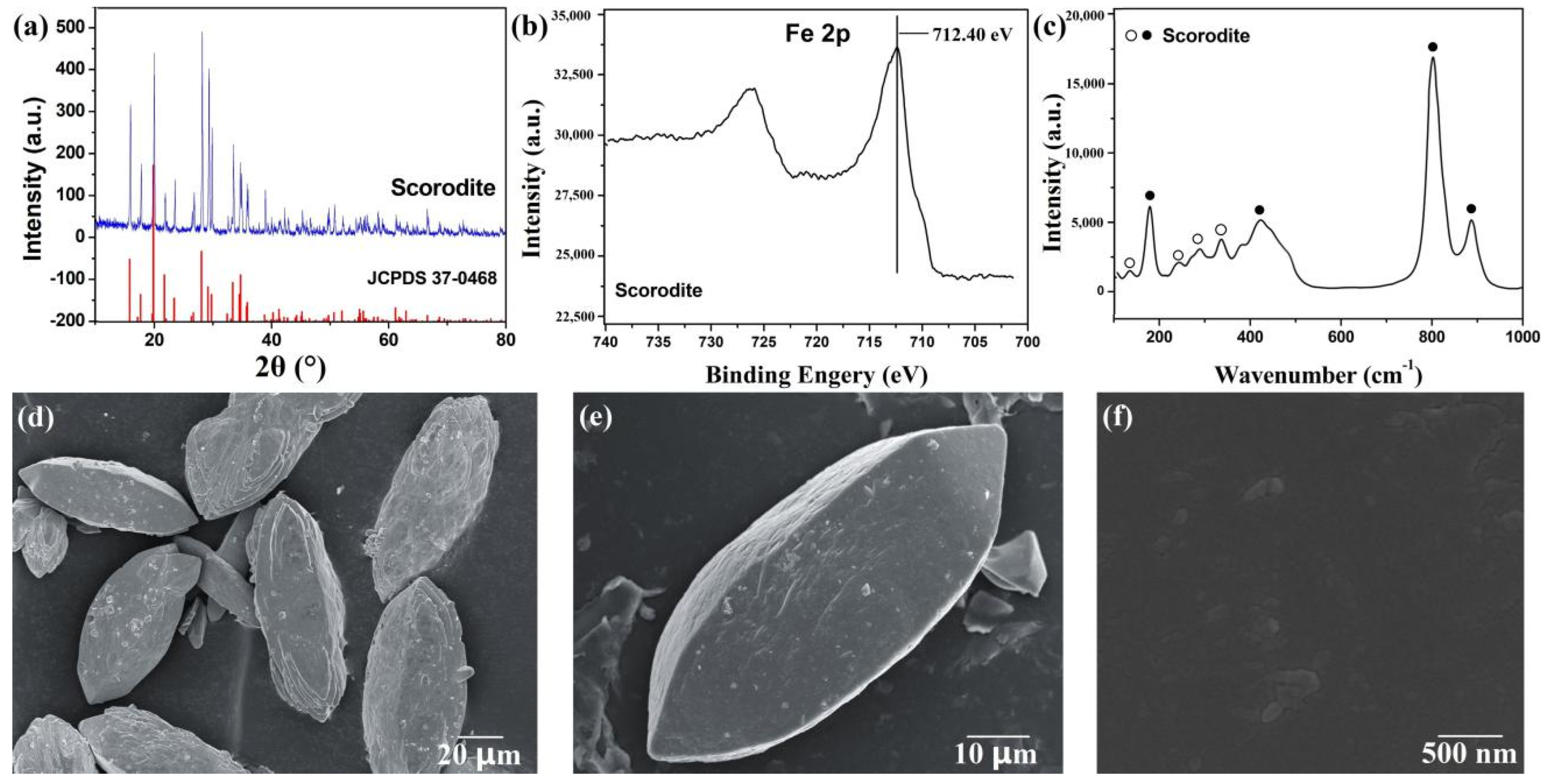
3.1. Characterization of the Scorodite

XRD analysis (Figure 1a) showed that the scorodite was synthesized successfully. The main peaks were located at approximately 19.8°, 28.0°, 15.8°, and 29.1°, which were respectively indexed as the (200), (212), (111), and (131) lattice planes of scorodite (FeAsO4·2H2O, JCPDS No. 37-0468) [37]. The high intensity of the diffraction peak indicated its high crystallinity. XPS analysis (Figure 1b) showed the peak at 712.40 eV attributed to the Fe 2p of scorodite [38]. Figure 1c shows the Raman spectrum of synthesized scorodite. Four strong bands appeared at ~799, ~889, ~180, and ~421 cm–1. while some weak bands appeared at ~135, ~243, ~291, ~336, ~378, and ~450 cm–1. The results were consistent with studies of Coleyshaw [39] and Das [40], indicating that the synthesized scorodite had high purity. SEM images (Figure 1d–f) show the morphology of synthesized scorodite. The scorodite crystals were spindle-shaped, the length was over 100 μm, and the diameter was about 30 μm. The surface of the synthesized scorodite was smooth. The cause of spindle-shaped scorodite formation was inhibition of the growth of (111) and (200) lattice planes because of the high H+ concentration solution. H+ could limit the formation and growth of (111) and (200) lattice planes; (212) lattice plane was the main lattice and grew, forming the spindle-shaped scorodite [40].

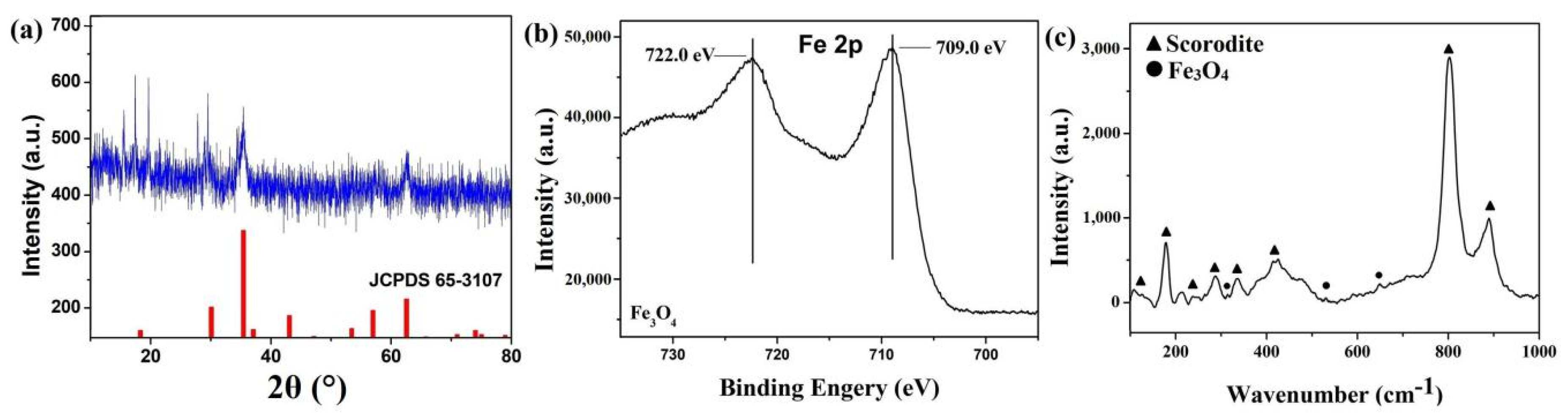
3.2. Characterization of Scorodite@Fe3O4

The synthesized core–shell materials under certain conditions were characterized to determine the composition (initial Fe ions/scorodite molar ratio = 9%; initial reaction pH = 8; reaction time = 30 min). XRD analysis (Figure 2a) showed the characteristic peaks of scorodite@Fe3O4. Compared with Figure 1a, the main peaks of scorodite located at approximately 19.8°, 28.0°, 15.8°, and 29.1° remained. The characteristic peaks of Fe3O4 located at approximately 35.4°, 62.6°, and 30.2° are consistent with the standard card of Fe3O4 (JCPDS No. 65-3107) [42]. The XRD pattern indicated that the Fe3O4 was synthesized successfully (Equation (2)). XPS is a surface-sensitive technique, probing the outermost 5–10 nm of the sample. From Figure 2b, Fe 2p is detected at 709.0 eV, and the satellite peak is located at 722.0 eV, corresponding to previous reports on Fe3O4 [43]. Moreover, by Raman analysis (Figure 2c), the characteristic peaks of scorodite remained. The peaks at 331, 524, and 670 cm–1 represent the existence of Fe3O4 as previously reported [44]. In summary, Fe3O4 was synthesized successfully, and the final products should have a scorodite/Fe3O4 composition. In order to determine whether the products had the desired core–shell structure, further tests were conducted.

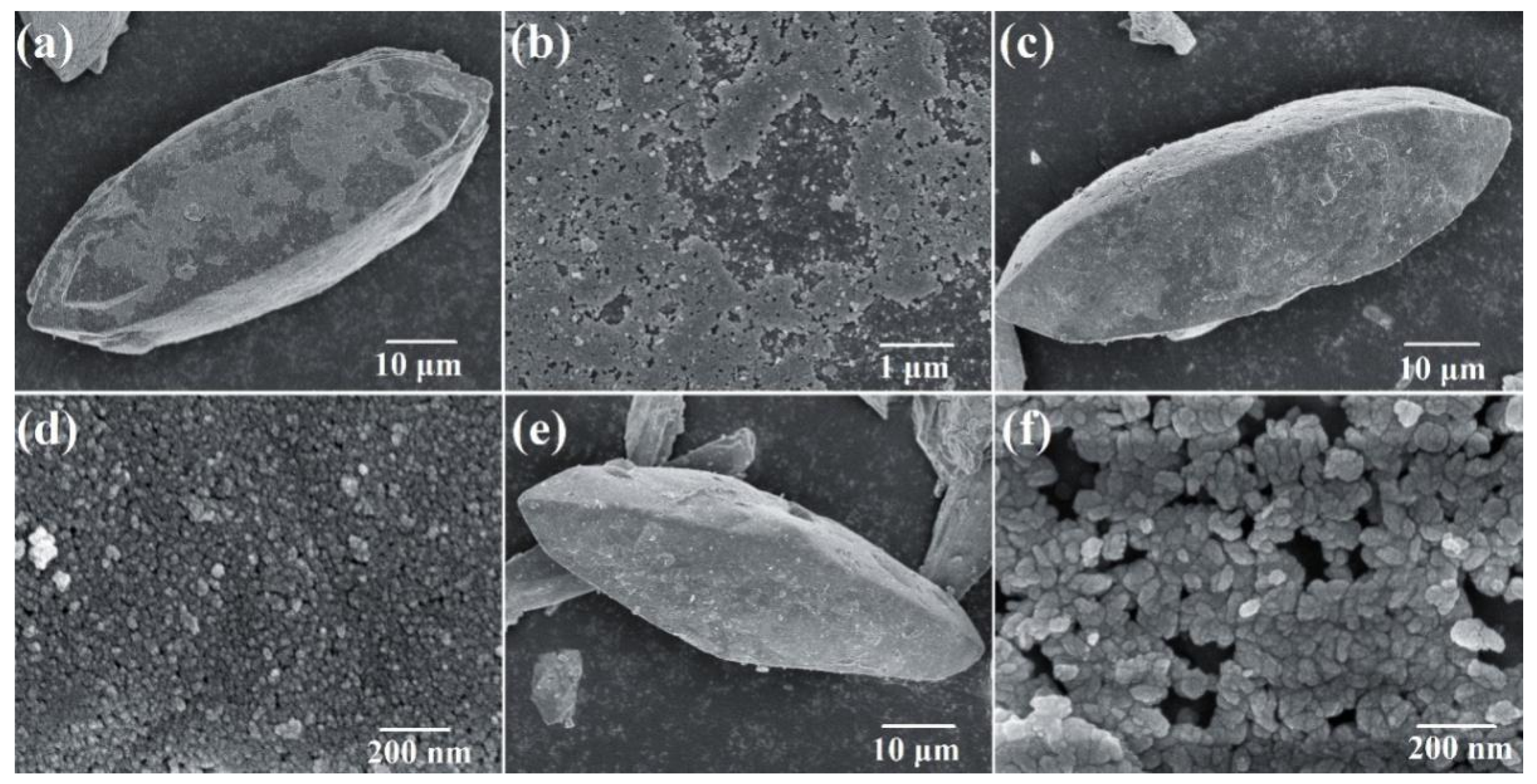
3.3. Morphology of Scorodite@Fe3O4

In order to figure out whether the products had a core–shell structure, SEM measurements were made. As shown in Figure 3, SEM images show the morphology of samples synthesized under different conditions. The results in Figure 3 show that core–shell structure materials were formed successfully as designed. Compared with Figure 1e, Figure 3a–c show that the scorodite could not be completely coated by Fe3O4 particles when the initial Fe ions/scorodite molar ratio was 1%, but could be when it was 9%. The reason was that there was not enough Fe3O4 when the initial molar ratio was 1%. Figure 3b,d,f show the sizes of Fe3O4 particles on the surface: ~10 nm when the reaction time was 15 min and ~30 nm when the reaction time was 35 min. The SEM image of the detail of sample 2 was shown in Figure S1. The size of Fe3O4 particles increased with the increased reaction time. Larger sizes should have better crystallinity and stability. Through XRD, Raman, XPS, and SEM analyses, the core–shell structure forming process could be inferred. When the reaction pH was close to neutral, for example pH = 8, the rate of Fe3O4 formation was much faster than the rate of scorodite corrosion by OH (Equations (3) and (4)) [29]. So, the deposition of Fe3O4 particles was the main behavior, and the Fe3O4 shell protected the scorodite core. In summary, the core–shell structure was formed successfully at pH 7 and 8 (Table 2).
Figure 4 shows the morphology of samples that were synthesized in pH 11 and 12 solution. The shells were incomplete and cracked. The reaction of Fe3O4 formation was too rapid when the reaction pH value was high (Equations (3) and (4)). The Fe3O4 precipitation did not have enough time to form a shell on the surface of scorodite crystals. Moreover, the high-pH alkaline solution could make the scorodite (FeAsO4·2H2O) hydrolyze (Equation (4)) [45]. Figure 4b shows that the scorodite crystals were damaged and the surface was corroded by OH. At this time, the formed Fe3O4 particles could not deposit on the surface of the scorodite crystals and form shells. Because the situation of the crystal surface was in chaos, this was the interface of mixed reactions.

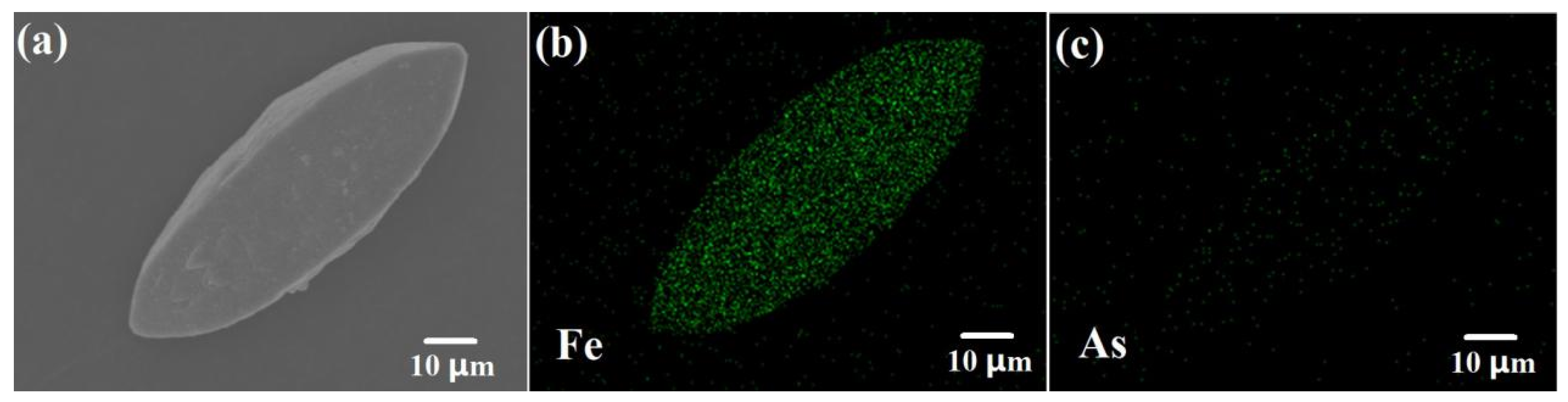
3.4. EDS Mapping Analysis of Scorodite@Fe3O4

Figure 5 shows the results of EDS mapping for scorodite@Fe3O4 (initial Fe ions/scorodite molar ratio = 9%; initial reaction pH = 7; reaction time = 35 min). As shown in Figure 5b,c, Fe was detected on the surface of the sample and As was not. This indicates that the shell does not contain As and that the scorodite was coated completely by Fe3O4.

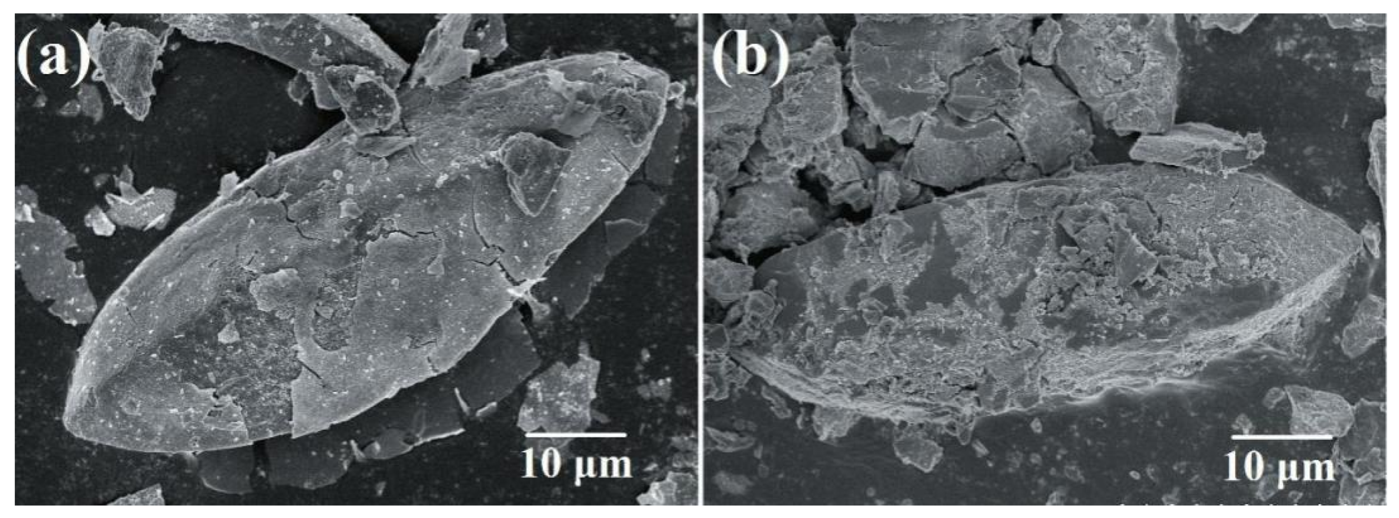
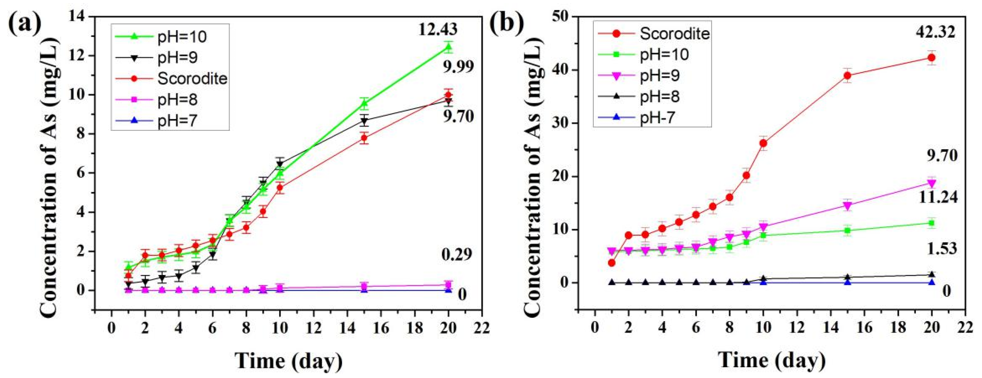
3.5. Stability Evaluation Analysis of Scorodite@Fe3O4

Table 2 shows the stability evaluation results of the synthesized scorodite@Fe3O4 under different conditions. The results indicate that the stability of scorodite@Fe3O4 increased with an increased amount of Fe3O4 coating. The leaching concentration of As for scorodite@Fe3O4 in acid and alkaline solution (pH 4.93 and 9.30) was lower than that of the uncoated scorodite when the initial Fe ions/scorodite molar ratio was 9% and the initial reaction pH was 7–10. Corresponding to the results of SEM tests, the reason was that the scorodite crystalline core could be coated better with the increased amount of Fe3O4 coating. When the initial Fe ions/scorodite molar ratio was 1% and 5%, the scorodite core could not be coated completely. The results of leaching tests indicated that the stability of scorodite@Fe3O4 increased with increased reaction time. When the reaction time was 35 min and the initial reaction pH was 7–10, the leaching concentration of As for scorodite@Fe3O4 in acid and alkaline solution (pH 4.93 and 9.30) was lower than that of the uncoated scorodite. Fe3O4 had more time to form and grow and the stability of the overall materials depended on its crystallinity. Corresponding to the results of SEM tests, the size of Fe3O4 particles was ~30 nm when the reaction time was 35 min, larger than the ~10 nm of the 15 min reaction.
The results indicated that the stability of scorodite@Fe3O4 decreased when the reaction pH was more than 10. The high pH alkaline solution could make the scorodite (FeAsO4·2H2O) hydrolyze (Equation (4)), the Fe–O–As bonds break, and Fe3+ and AsO43– release into the solution [44]. Meanwhile, Fe–O–H, Fe–O–OH, or Fe–O–Fe–O–H bonds are formed on the surface of scorodite due to the release of Fe3+ and AsO43– ions (Supplementary Figure S2). Then the surface would be a Fex(OH)y–AsO4 layer. It is known that arsenical ferrihydrite has low stability and is hydrolyzed easily in acid/alkaline solution [46]. So during the leaching tests, AsO43– ions were released into the solution. These led to a higher leaching concentration of As than of the uncoated scorodite, because the structure of the scorodite surface was damaged by a high concentration of OH.
According to the previous analysis, the conditions of synthesizing scorodite@Fe3O4 should be as follows: initial Fe ions/scorodite molar ratio = 9%; initial reaction pH = 7, 8, 9, and 10; and reaction time = 35 min. The samples that were synthesized under these conditions had better stability than the uncoated scorodite. Long-term leaching tests were conducted in order to evaluate the stability of these scorodite@Fe3O4 core–shell structure materials. Figure 6a shows the leaching concentrations of As extraction liquid by TCLP tests at pH 4.93 ± 0.05 from 1 to 20 days. The results show that the samples synthesized in pH 7 or 8 solution had excellent stability. The leaching concentrations of As extraction liquid were 0 and 0.29 mg·L–1 after 20 days, lower than the 9.99 mg·L–1 of uncoated scorodite. However, the samples synthesized in pH 9 or 10 solution had less stability than uncoated scorodite. Under alkaline conditions (Figure 6b), the As leaching concentration of samples synthesized at pH 7 and 8 was kept below 2 mg·L–1 after 20 days due to the formation of a protective Fe3O4 shell. It is known that Fe3O4 is chemically inert in alkaline solution. For the uncoated scorodite hydrolyzed in the alkaline solution, the leaching concentration of As was 42.43 mg·L–1 after 20 days.
Combined with the analysis above, the reason why scorodite@Fe3O4 had excellent stability was that the inert Fe3O4 shell could prevent the scorodite core from being corroded by the external solution. When the reaction pH was 7 or 8, the rate of Fe3O4 formation was much faster than the rate of scorodite corrosion by OH (Equations (3) and (4)). Thus, the deposition of Fe3O4 particles was the main behavior and the Fe3O4 shell formed. Fe3O4 could be stable in a weak acid and alkaline solution environment. This property made the overall materials stable. However, the samples synthesized in pH 9 and 10 solution were not stable enough, and the reason should be same as the previous analysis. A high concentration of OH would increase the hydrolysis rate of scorodite, and affect the deposition of Fe3O4 particles, and as a result the shell could not form. Meanwhile, an unstable Fex(OH)y–AsO4 layer formed. During the leaching tests, the Fex(OH)y–AsO4 dissolved and released As ions. Hence, the stability of the samples was lower than that of uncoated scorodite. The leaching concentration of As extraction liquid in weak acid and alkaline solution was 0 mg·L–1 after 20 days.

4. Conclusions

Scorodite@Fe3O4 core–shell structure materials were synthesized by a simple method. The scorodite crystals were synthesized first, then the Fe3O4 nanoparticles were produced and deposited on the surface of the scorodite crystals, and finally Fe3O4 shells formed. Through XRD, SEM, XPS, Raman, and EDS analysis of the synthesized core–shell materials, it was confirmed the core was FeAsO4·2H2O and the shell was Fe3O4. Through SEM analysis and leaching tests, the best synthesis condition was confirmed. The initial Fe ions/scorodite molar ratio was 9%, the initial reaction pH was 7 and 8, and the reaction time was 35 min. A long-term leaching test was conducted to evaluate the stability of these scorodite@Fe3O4 core–shell structure materials, and the results indicated that they had excellent stability. The inert Fe3O4 shell could prevent the scorodite core from being corroded by the external solution. The scorodite@Fe3O4 core–shell structure material was suitable for the immobilization of arsenic and has potential application prospects for the treatment of arsenic-containing waste.

Supplementary Materials

The following are available online at https://www.mdpi.com/2079-6412/9/8/523/s1, Table S1: Components of dust, Table S2: Components of leaching liquid, Figure S1: The SEM image of Sample 2 (initial Fe ions/Scorodite molar ratio= 9%, initial reaction pH= 8, reaction time= 15 min), Figure S2: Schematic diagram of the forming process of Fex(OH)y-AsO4 layer.

Author Contributions

Conceptualization, Y.W. and X.T.; Methodology, Y.W.; Data Curation, Y.W. and Z.R.; Funding Acquisition, X.T. and S.C.; Writing–Original Draft Preparation, Y.W.; Writing–Review and Editing, S.C.

Funding

This research was supported by the National Natural Science Foundation of China (Nos. 21476268 and 21808170) and the Shandong Provincial Natural Science Foundation (No. ZR201807260006).

Acknowledgments

We gratefully acknowledge Shan Cao for the SEM measurements.

Conflicts of Interest

The authors declare no conflict of interest.

References

  1. Fakhri, Y.; Bjørklund, G.; Bandpei, A.M.; Chirumbolo, S.; Keramati, H.; Pouya, R.H.; Asadi, A.; Amanidaz, N.; Sarafraz, M.; Sheikhmohammad, A. Concentrations of arsenic and lead in rice (Oryza sativa L.) in Iran: A systematic review and carcinogenic risk assessment. Food Chem. Toxicol. 2018, 113, 267–277. [Google Scholar] [CrossRef] [PubMed]
  2. Li, G.; Khan, S.; Ibrahim, M.; Sun, T.-R.; Tang, J.-F.; Cotner, J.B.; Xu, Y.-Y. Biochars induced modification of dissolved organic matter (DOM) in soil and its impact on mobility and bioaccumulation of arsenic and cadmium. J. Hazard. Mater. 2018, 348, 100–108. [Google Scholar] [CrossRef] [PubMed]
  3. Neff, J.M. Ecotoxicology of arsenic in the marine environment. Environ. Toxicol. Chem. 1997, 16, 917–927. [Google Scholar] [CrossRef]
  4. Bretzler, A.; Lalanne, F.; Nikiema, J.; Podgorski, J.; Pfenninger, N.; Berg, M.; Schirmer, M. Groundwater arsenic contamination in Burkina Faso, West Africa: Predicting and verifying regions at risk. Sci. Total Environ. 2017, 584, 958–970. [Google Scholar] [CrossRef] [PubMed]
  5. Jomova, K.; Jenisova, Z.; Feszterova, M.; Baros, S.; Liska, J.; Hudecova, D.; Rhodes, C.; Valko, M. Arsenic: Toxicity, oxidative stress and human disease. J. Appl. Toxicol. 2011, 31, 95–107. [Google Scholar] [CrossRef] [PubMed]
  6. Jaishankar, M.; Tseten, T.; Anbalagan, N.; Mathew, B.B.; Beeregowda, K.N. Toxicity, mechanism and health effects of some heavy metals. Interdiscip. Toxicol. 2014, 7, 60–72. [Google Scholar] [CrossRef] [PubMed] [Green Version]
  7. Ravenscroft, P.; Brammer, H.; Richards, K. Arsenic Pollution: A Global Synthesis; John Wiley & Sons: Hoboken, NJ, USA, 2009; Volume 28. [Google Scholar]
  8. Vadahanambi, S.; Lee, S.-H.; Kim, W.-J.; Oh, I.-K. Arsenic removal from contaminated water using three-dimensional graphene-carbon nanotube-iron oxide nanostructures. Environ. Sci. Technol. 2013, 47, 10510–10517. [Google Scholar] [CrossRef] [PubMed]
  9. Leonard, R.L.; Whellock, J.G. Extraction or Recovery of Non-Ferrous Metal Values from Arsenic-Containing Materials. U.S. Patent 5,482,534A, 9 January 1996. [Google Scholar]
  10. Dudka, S.; Adriano, D.C. Environmental impacts of metal ore mining and processing: A review. J. Environ. Qual. 1997, 26, 590–602. [Google Scholar] [CrossRef]
  11. Agrawal, A.; Sahu, K.; Pandey, B. Solid waste management in non-ferrous industries in India. Resour. Conserv. Recycl. 2004, 42, 99–120. [Google Scholar] [CrossRef]
  12. Wei, C.; Jiang, Q.; Luo, T.; Huang, M. Arsenic removal and recovery in heavy metals smelting process. Min. Res. Dev. 2003, 2, 1. [Google Scholar]
  13. Mukherjee, A.B. Arsenic flows in the environment of the European Union: A synoptic review. Trace Met. Other Contam. Environ. 2007, 9, 527–547. [Google Scholar]
  14. Ferguson, J.F.; Gavis, J. A review of the arsenic cycle in natural waters. Water Res. 1972, 6, 1259–1274. [Google Scholar] [CrossRef]
  15. Li, Y.; Wang, Y.B.; Guo, X.; Su, Y.B.; Wang, G. Risk assessment of heavy metals in soils and vegetables around non-ferrous metals mining and smelting sites, Baiyin, China. J. Environ. Sci. 2006, 18, 1124–1134. [Google Scholar]
  16. Leist, M.; Casey, R.; Caridi, D. The management of arsenic wastes: Problems and prospects. J. Hazard. Mater. 2000, 76, 125–138. [Google Scholar] [CrossRef]
  17. Sullivan, C.; Tyrer, M.; Cheeseman, C.R.; Graham, N.J. Disposal of water treatment wastes containing arsenic—A review. Sci. Total Environ. 2010, 408, 1770–1778. [Google Scholar] [CrossRef] [PubMed]
  18. Zhan, L.; Li, J.; Xie, B.; Xu, Z. Recycling arsenic from gallium arsenide scraps through sulfurizing thermal treatment. ACS Sustain. Chem. Eng. 2017, 5, 3179–3185. [Google Scholar] [CrossRef]
  19. Bothe, J.V.; Brown, P.W. Arsenic immobilization by calcium arsenate formation. Environ. Sci. Technol. 1999, 33, 3806–3811. [Google Scholar] [CrossRef]
  20. Coussy, S.; Benzaazoua, M.; Blanc, D.; Moszkowicz, P.; Bussière, B. Assessment of arsenic immobilization in synthetically prepared cemented paste backfill specimens. J. Environ. Manag. 2012, 93, 10–21. [Google Scholar] [CrossRef]
  21. Palfy, P.; Vircikova, E.; Molnar, L. Processing of arsenic waste by precipitation and solidification. Waste Manag. 1999, 19, 55–59. [Google Scholar] [CrossRef]
  22. Ahoranta, S.H.; Kokko, M.E.; Papirio, S.; Özkaya, B.; Puhakka, J.A. Arsenic removal from acidic solutions with biogenic ferric precipitates. J. Hazard. Mater. 2016, 306, 124–132. [Google Scholar] [CrossRef]
  23. Lim, K.; Shukor, M.; Wasoh, H. Physical, chemical, and biological methods for the removal of arsenic compounds. BioMed Res. Int. 2014, 2014, 503784. [Google Scholar] [CrossRef] [PubMed]
  24. Wang, S.; Zhao, X. On the potential of biological treatment for arsenic contaminated soils and groundwater. J. Environ. Manag. 2009, 90, 2367–2376. [Google Scholar] [CrossRef] [PubMed]
  25. Bluteau, M.-C.; Becze, L.; Demopoulos, G.P. The dissolution of scorodite in gypsum-saturated waters: Evidence of Ca–Fe–AsO4 mineral formation and its impact on arsenic retention. Hydrometallurgy 2009, 97, 221–227. [Google Scholar] [CrossRef]
  26. Nikolaidis, N.P.; Dobbs, G.M.; Lackovic, J.A. Arsenic removal by zero-valent iron: Field, laboratory and modeling studies. Water Res. 2003, 37, 1417–1425. [Google Scholar] [CrossRef]
  27. Zhu, H.; Jia, Y.; Wu, X.; Wang, H. Removal of arsenic from water by supported nano zero-valent iron on activated carbon. J. Hazard. Mater. 2009, 172, 1591–1596. [Google Scholar] [CrossRef] [PubMed]
  28. Paktunc, D.; Bruggeman, K. Solubility of nanocrystalline scorodite and amorphous ferric arsenate: Implications for stabilization of arsenic in mine wastes. Appl. Geochem. 2010, 25, 674–683. [Google Scholar] [CrossRef]
  29. Fujita, T.; Fujieda, S.; Shinoda, K.; Suzuki, S. Environmental leaching characteristics of scorodite synthesized with Fe (II) ions. Hydrometallurgy 2012, 111, 87–102. [Google Scholar] [CrossRef]
  30. Le Berre, J.; Gauvin, R.; Demopoulos, G. A study of the crystallization kinetics of scorodite via the transformation of poorly crystalline ferric arsenate in weakly acidic solution. Colloids Surf. A Physicochem. Eng. Asp. 2008, 315, 117–129. [Google Scholar] [CrossRef]
  31. Mirzaei, A.; Janghorban, K.; Hashemi, B.; Bonavita, A.; Bonyani, M.; Leonardi, S.G.; Neri, G. Synthesis, characterization and gas sensing properties of Ag@α-Fe2O3 core–shell nanocomposites. Nanomaterials 2015, 5, 737–749. [Google Scholar] [CrossRef]
  32. Ke, P.-C.; Liu, Z.-H. Synthesis, in-situ coating and characterization of scorodite with high leaching stability. Trans. Nonferrous Met. Soc. China 2019, 29, 876–892. [Google Scholar] [CrossRef]
  33. Saif, S.; Tahir, A.; Chen, Y. Green synthesis of iron nanoparticles and their environmental applications and implications. Nanomaterials 2016, 6, 209. [Google Scholar] [CrossRef] [PubMed]
  34. He, Q.; Liu, J.; Liu, X.; Li, G.; Chen, D.; Deng, P.; Liang, J. Fabrication of amine-modified magnetite-electrochemically reduced graphene oxide nanocomposite modified glassy carbon electrode for sensitive dopamine determination. Nanomaterials 2018, 8, 194. [Google Scholar] [CrossRef] [PubMed]
  35. Chen, C.; Jiang, X.; Kaneti, Y.V.; Yu, A. Design and construction of polymerized-glucose coated Fe3O4 magnetic nanoparticles for delivery of aspirin. Powder Technol. 2013, 236, 157–163. [Google Scholar] [CrossRef]
  36. Kendall, D.S. Toxicity characteristic leaching procedure and iron treatment of brass foundry waste. Environ. Sci. Technol. 2003, 37, 367–371. [Google Scholar] [CrossRef] [PubMed]
  37. Baghurst, D.R.; Barrett, J.; Coleyshaw, E.E.; Griffith, W.P.; Mingos, D.M.P. Microwave techniques for the synthesis and deuteration of minerals, with particular reference to scorodite, FeAsO4.2H2O. Mineral. Mag. 1996, 60, 821–828. [Google Scholar] [CrossRef]
  38. Frau, F.; Addari, D.; Atzei, D.; Biddau, R.; Cidu, R.; Rossi, A. Influence of major anions on As (V) adsorption by synthetic 2-line ferrihydrite. Kinetic investigation and XPS study of the competitive effect of bicarbonate. Water Air Soil Pollut. 2010, 205, 25–41. [Google Scholar] [CrossRef]
  39. Coleyshaw, E.E.; Griffith, W.P.; Bowell, R.J. Fourier-transform Raman spectroscopy of minerals. Spectrochim. Acta Part A Mol. Spectrosc. 1994, 50, 1909–1918. [Google Scholar] [CrossRef]
  40. Fujita, T.; Taguchi, R.; Abumiya, M.; Matsumoto, M.; Shibata, E.; Nakamura, T. Effect of pH on atmospheric scorodite synthesis by oxidation of ferrous ions: Physical properties and stability of the scorodite. Hydrometallurgy 2009, 96, 189–198. [Google Scholar] [CrossRef]
  41. Das, S.; Hendry, M.J. Application of Raman spectroscopy to identify iron minerals commonly found in mine wastes. Chem. Geol. 2011, 290, 101–108. [Google Scholar] [CrossRef]
  42. Tong, G.; Wu, W.; Guan, J.; Qian, H.; Yuan, J.; Li, W. Synthesis and characterization of nanosized urchin-like α-Fe2O3 and Fe3O4: Microwave electromagnetic and absorbing properties. J. Alloy. Compd. 2011, 509, 4320–4326. [Google Scholar] [CrossRef]
  43. Hu, C.; Gao, Z.; Yang, X. Fabrication and magnetic properties of Fe3O4 octahedra. Chem. Phys. Lett. 2006, 429, 513–517. [Google Scholar] [CrossRef]
  44. Muraliganth, T.; Murugan, A.V.; Manthiram, A. Facile synthesis of carbon-decorated single-crystalline Fe3O4 nanowires and their application as high performance anode in lithium ion batteries. Chem. Commun. 2009, 47, 7360–7362. [Google Scholar] [CrossRef] [PubMed]
  45. Zhu, Y.; Merkel, B. The dissolution and solubility of scorodite, FeAsO4 2H2O: Evaluation and simulation with PHREEQC2. Wiss. Mitt. Inst. Geol. Tech. Univ. Bergakad. Freib. 2001, 18, 72–87. [Google Scholar]
  46. Paktunc, D.; Dutrizac, J.; Gertsman, V. Synthesis and phase transformations involving scorodite, ferric arsenate and arsenical ferrihydrite: Implications for arsenic mobility. Geochim. Cosmochim. Acta 2008, 72, 2649–2672. [Google Scholar] [CrossRef]
Figure 1. (a) X-ray diffraction (XRD) pattern, (b) X-ray photoelectron spectroscopy (XPS) spectrum, (c) Raman spectrum, (d–f) SEM images of the as-synthesized scorodite.
Coatings 09 00523 g001
Figure 2. (a) XRD pattern, (b) XPS spectrum, and (c) Raman spectrum of as-synthesized scorodite@Fe3O4 (initial Fe ions/scorodite molar ratio = 9%; initial reaction pH = 8; reaction time = 35 min).
Coatings 09 00523 g002
Figure 3. SEM images of (a,b) Sample 1 (initial Fe ions/scorodite molar ratio = 1%; initial reaction pH = 8; reaction time = 15 min), (c,d) Sample 2 (initial Fe ions/scorodite molar ratio = 9%; initial reaction pH = 8; reaction time = 15 min), and (e,f) Sample 3 (initial Fe ions/scorodite molar ratio = 9%; initial reaction pH = 8; reaction time = 35 min).
Coatings 09 00523 g003
Figure 4. SEM images of (a) Sample 4 (initial Fe ions/scorodite molar ratio = 9%; initial reaction pH = 11; reaction time = 35 min) and (b) Sample 5 (initial Fe ions/scorodite molar ratio = 9%; initial reaction pH = 12; reaction time = 15 min).
Coatings 09 00523 g004
Figure 5. (a) Location SEM image; (b) Fe and (c) As image of energy-dispersive X-ray spectroscopy (EDS) mapping for scorodite@Fe3O4 (initial Fe ions/scorodite molar ratio = 9%; initial reaction pH = 7; reaction time = 35 min).
Coatings 09 00523 g005
Figure 6. Leaching concentrations of arsenic over 20 days. Scorodite and scorodite@Fe3O4 (initial Fe ions/scorodite molar ratio = 9%; initial reaction pH = 7, 8, 9, 10; reaction time = 35 min) with (a) pH 4.93 and (b) pH 9.30 solution. The scorodite@Fe3O4 samples were synthesized at the indicated pH values and subsequently tested for stability using acidic and alkaline leaching solutions.
Coatings 09 00523 g006
Table 1. Components of dust and leaching liquid (Data are provided as means +/− scanning electron microscopy (SEM); n = 3).
ElementsAsKAlZnNa
Dust (wt %)42.3 ± 1.00.6 ± 0.10.1 ± 0.00.5 ± 0.10.3 ± 0.1
Leach liquid (g·L–1)22.5 ± 2.20.6 ± 0.20.01 ± 0.00.01 ± 0.00.2 ± 0.1
Table 2. Stability evaluation results of synthesized scorodite@Fe3O4 under different conditions (toxicity characteristic leaching procedure (TCLP) 1: pH = 4.93, 18 h; TCLP 2: pH = 9.30, 24 h; 3 stars is the highest and 1 star is the lowest quality).
SampleInitial Fe Ions/Scorodite Molar Ratio (%)Reaction Time (min)Initial Reaction pHConcentration of As (TCLP 1; mg·L−1)Concentration of As (TCLP 2; mg·L−1)Quality of Fe3O4 Shell (1–3 Stars)
Scorodite0.671 ± 0.0123.754 ± 0.125
1115700.994 ± 0.0092
251570.004 ± 0.0010.136 ± 0.0112
39157003
4115800.955 ± 0.0122
5515800.624 ± 0.0102
69158003
79257003
89357003
99258003
109358003
1191590.354 ± 0.0166.091 ± 0.1721
12915100.967 ± 0.0213.194 ± 0.0462
139251001.873 ± 0.1042
149351001.592 ± 0.1202
15915111.258 ± 0.0337.031 ± 0.1631
16915125.174 ± 0.10612.68 ± 0.1181
1711590.549 ± 0.0287.183 ± 0.0491
1851590.487 ± 0.0216.627 ± 0.0941
1992590.138 ± 0.0143.734 ± 0.0432
20935900.982 ± 0.0112
21115101.691 ± 0.0268.735 ± 0.1141
22515101.172 ± 0.0355.549 ± 0.0731
23115112.054 ± 0.0139.723 ± 0.0471
24515111.813 ± 0.0917.871 ± 0.0831
25925110.749 ± 0.0104.312 ± 0.1441
26935110.498 ± 0.0333.165 ± 0.0751
27115127.682 ± 0.07215.36 ± 0.1481
28515126.235 ± 0.08413.44 ± 0.1621
29925124.058 ± 0.10311.78 ± 0.0921
30935123.262 ± 0.06210.24 ± 0.1361

