1. Introduction
Joining metals to polymers has gained prominent interest among researchers and industries because of its ability to produce lightweight hybrid structures with tailored properties. Conventional metal–polymer joining methods, such as adhesive bonding, mechanical fastening, friction stir welding, and ultrasonic joining, have their drawbacks, as they either require high processing time, involve hazardous chemicals, cause excessive tool wear, involve geometrical constrains, or require the addition of weight to the component. The thermal joining of metals to polymers is challenging because of the significant difference of the thermal properties and melting temperatures of both materials. However, Laser-Assisted Metal–Polymer joining (LAMP) provides the ability to precisely control the energy input into the materials, giving the opportunity to thoroughly melt the polymer at the interface of the joint, while, at the same time, avoiding its degradation. In addition, LAMP has its advantages over conventional joining methods in being rapid, autogenous, and a non-contact process that offers design flexibility, along with the ability to produce miniaturized joints and minimize overlapping dimensions.
So far, research in LAMP has shown the reliability of the laser welding process in a variety of material combinations [
1,
2,
3,
4]. Preliminary surface treatments before welding have shown a significant impact on the joint strength and quality. Researchers [
3,
4,
5,
6,
7,
8,
9,
10,
11,
12] reported the effects of several surface pretreatments on LAMP, including mechanical, chemical, electrochemical, and laser pretreatments for metals, as well as plasma and UV ozone pretreatment for polymers. Similar to adhesive bonding, two main factors were reported in the literature as affecting the LAMP joint properties: mechanical interlocking and physicochemical bonding. However, although LAMP is a thermal joining process, the effect of surface pretreatments on the thermal transfer between the joining partners during the laser welding process, and on the joint quality, has not been investigated.
Increased surface roughness has shown to have a positive effect on enhancing LAMP joint strength by increasing mechanical interlocking effects [
9,
10,
12]. Furthermore, an increased surface roughness might increase the surface wettability of treated metal, which in turns allows a better wetting of the molten polymer during the laser welding process. However, an increase in surface roughness results in an increase in the thermal contact resistance (TCR) across the interface of the two solid materials in contact [
13,
14]. When two solid surfaces come into contact, the flow of heat across the interface is mainly governed by solid-to-solid conduction at the points of contact, and conduction through the fluid occupying the noncontact area, resulting in restrictions to the heat flow [
15]. Yovanovich [
16] summarizes forty years of research in the field of thermal contact resistance, and in particular introduces the development of a geometric–mechanical–thermal model called the Cooper–Mikic–Yovanovich (CMY) model to predict the thermal contact resistance of conforming rough surfaces.
Researchers [
17,
18,
19,
20,
21,
22] developed several theoretical models to calculate thermal contact resistance. Three mechanical models—elastic, plastic, or elastic–plastic deformation of the surface asperities— were considered, assuming that surface asperities follow Gaussian height distributions about a mean plane passing through each surface, and assuming that surface asperities are randomly distributed over the apparent contact area. Yovanovich [
23] summarized the TCR model developed by Cooper et al. [
20] and proposed compact expression to calculate the TCR between two nominally flat solid surfaces (1 and 2) in contact assuming plastic deformation of asperities as given by Equation (1). Given that σ
1,
m1,
k1 are properties of material 1, and σ
2,
m2,
k2 are properties of material 2, σ = (σ
12 + σ
22)
0.5 is the effective root mean square roughness (RMS) so that σ
1,2 =
, where
L is the profile traced length;
m = (
m12 +
m22)
0.5 is the effective mean asperity slope, and
m1,2 =
is the mean absolute asperity slope.
H is the microhardness of the softer material,
P is the applied pressure, and
kh is the harmonic mean thermal conductivity at the interface where
kh = 2
k1k2/(
k1 +
k2). It is clear from Equation (1), which can be utilized in describing the TCR between metal and polymer in their solid state, prior to the laser joining process [
24], that TCR has a proportional relation to the ratio of the root mean square roughness σ to the asperities slope,
m.
Laser ablation was proven to be an effective and rapid surface pretreatment technique for aluminum (Al 1050) to enhance the bonding strength when welded with polyamide (PA 6.6) [
1,
5,
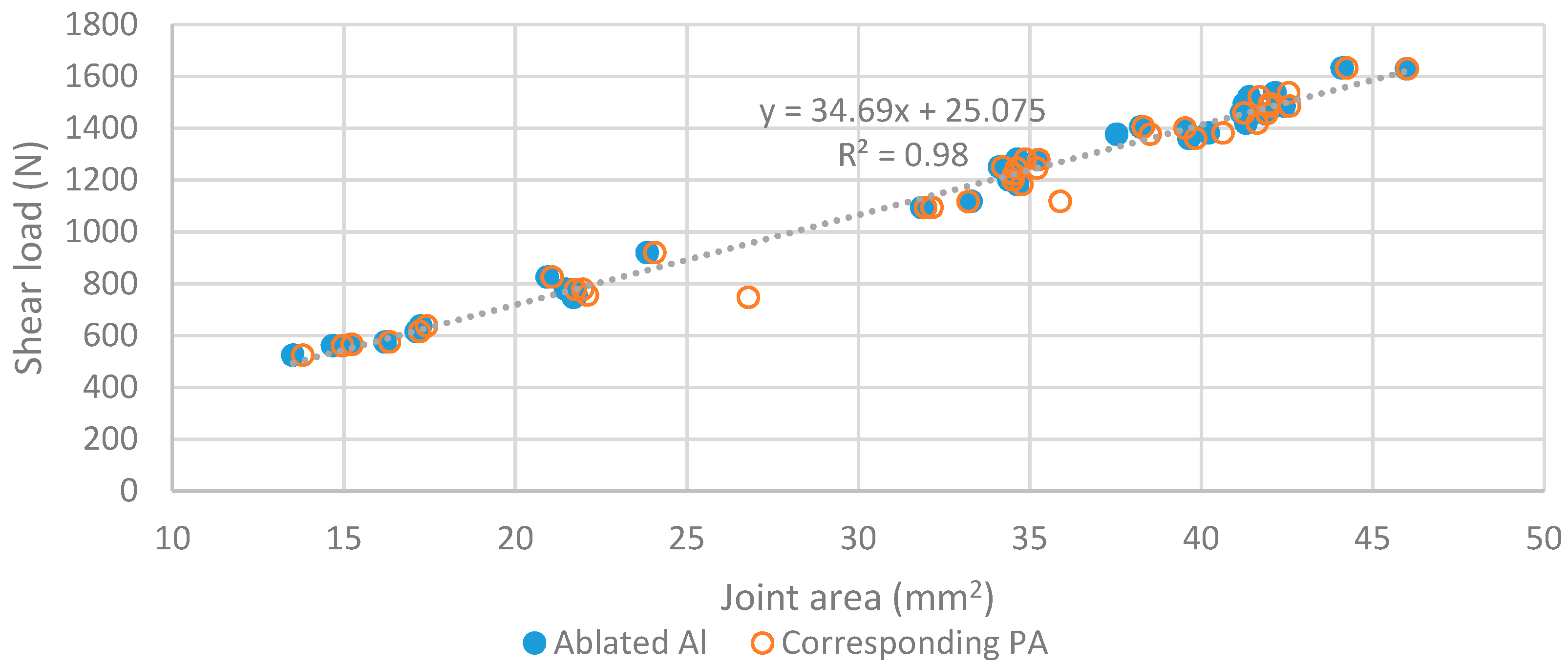
25]. It was already demonstrated that laser-ablation parameters have a strong impact on the joint quality, demonstrated by the joint area and its resistance to failure, but no effect on the joint strength, i.e., its stress to failure [
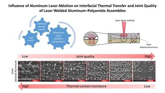
5]. Results have shown the prominence of cohesive failure mode indicating that interfacial adhesion is not the only factor influencing the joint quality. Preliminary results showed that the joint resistance to failure is influenced by the topography of the ablated aluminum surface, in particular by topography parameters representing the density of peaks on the surface. From the knowledge of TCR models quoted before, it is therefore hypothesized that laser-ablation parameters affect the thermal transfer between the joining partners, which would reflect on the joint area and quality, impacting its resistance to shear load. This research aims at understanding the effects of surface properties on the interfacial thermal transfer between laser ablated Al 1050 joined to PA 6.6 using laser-beam welding. It correlates the influence of surface topography and the chemistry of aluminum modified layer to the TCR and reports their consecutive effects on the joint quality. To the best of the authors’ knowledge, this is the first time that the prominence of the TCR for the welding quality is evidenced in LAMP.
2. Experimental Method
2.1. Materials
In those experiments, 0.5 mm thick EN-AW1050A aluminum (Al) in half-hard state, with geometry of 30 mm × 60 mm, and 4 thick mm polyamide 6.6 (PA) purchased from Dutec (Ahaus, Germany), with the dimensions of 25 mm × 75 mm were used. Prior to the joining process, Al samples were prepared by laser ablation, and PA samples were wiped with ethanol, to remove potential surface contaminants.
2.2. Laser Ablation
Al surfaces were ablated, using a short-pulsed (ns) Nd:YVO4 laser (TruMark 6130 from TRUMPF, Ditzingen, Germany), with a wavelength of 1064 nm and spot size of 45 µm. Al-Sayyad et al. [
5] already demonstrated that, from seven different ablation parameters, namely pulse frequency (
fp), beam guidance speed (
V), lines, focal position, Al rolling direction, ablation hatching orientation, and laser beam power percentage, only
fp and
V had a significant influence on laser welded Al–PA joints’ resistance to shear failure. This research focuses on further evaluating the effects of those significant laser-ablation conditions, as shown in
Table 1, on Al surface properties, thermal transfer across the joining partners, and corresponding joint quality. Based on previous investigations [
5], six ablation conditions (see
Table 1) were chosen for this research, as they resulted in a wide range of joint quality. Since ablation was performed with a q-switched laser, increasing pulse frequency results in decreasing the peak pulse power and fluence of the laser beam. However, overlap ratio between consecutive laser pulses (see
Figure 1) depends on both pulse frequency and beam guidance speed, as described by Equation (2).
2.3. Laser-Beam Welding
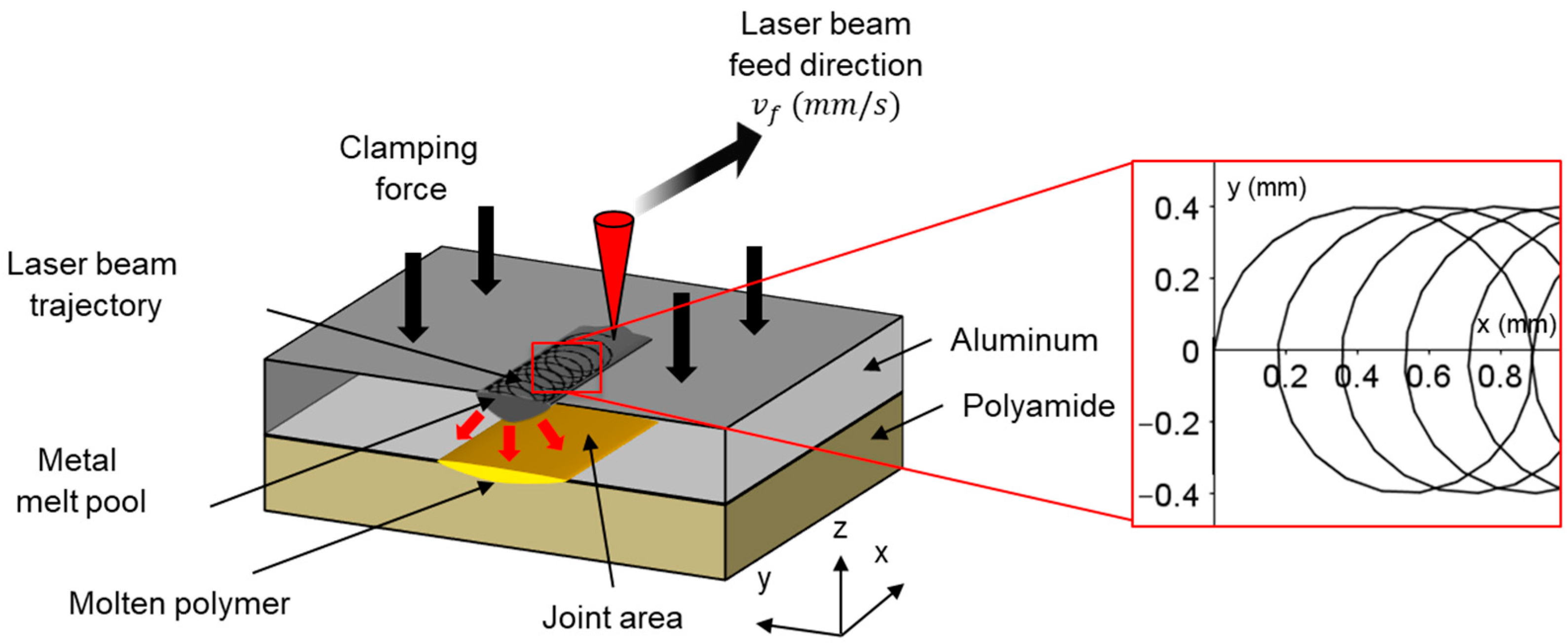
Laser welding was performed with a fiber laser (TruFiber 400 from TRUMPF), with a wavelength of 1070 nm and a calculated spot size of 58 µm, irradiated on the Al surface after clamping the parts in an overlap configuration, as shown in
Figure 2. A peak pulse power of 400 W was modulated with a pulse frequency of 25 kH and pulse duration of 35 µs. The laser beam followed a spiral trajectory, with a feed velocity (
) of 88.8 mm/s. Part of the irradiated laser-beam energy gets absorbed, converted to heat energy, conducted through the Al, and transferred to melt PA, thereby joining Al to PA. However, heat transfer across the interface depends on the TCR.
Figure 3 shows a simplified illustration of the hypothesized thermal-energy transfer of the irradiated laser beam across the interface in the case of (a) ideal flat surfaces and (b) across rough ablated Al surfaces in contact with smooth PA modeling “real life” conditions. The presence of surface asperities at the interface causes the thermal transfer by conduction to take place mostly at the points of contact [
16], thereby increasing TCR and reducing the thermal energy transfer across the interface. Single lap shear tests were performed by using Z010 from Zwick/Roell (Ulm, Germany). Samples were clamped in a vertical alignment, with a jaw-to-jaw distance of 75 mm. The crosshead pulling speed was set at 2.21 mm/min.
2.4. Joint-Area Assessment
In order to quantify the joint area, a dedicated experimental approach was developed. First, macroscopic images of the joint interface after failure were obtained by using a digital FUJIFILM X-Pro2 camera (Tokyo, Japan). Next, the dimensions of a single pixel were measured, using GIMP software (2.10), by correlating to a predefined scale positioned on the sample close to the weld zone. Then, the coordinates outlining the joint area were allocated, and the joint area was measured by counting the number of pixels and correlating them to the measured pixel dimension. Polarized and stitched microscopic images of the joint area were used to confirm the measurements.
2.5. X-Ray Photoelectron Spectroscopy (XPS)
The atomic composition of treated surfaces and its chemical-bonding states were investigated, using a K-alpha from Thermo Scientific (Waltham, MA, USA). An X-ray beam (Al Kα, 1486.6 eV) with a spot size of 300 μm was used in the analysis. Six regions of 1 cm
2 area were ablated on an Al sample, each region with different ablation condition (see
Table 1). Six points per ablated region were investigated by measuring a survey spectrum (3 scans, 200 eV energy pass) and high-resolution spectra for the regions of Al 2
p, O 1
s, and C 1
s (20 scans, 20 eV pass energy) atoms.
2.6. Scanning Electron Microscope (SEM)
A pressure-controlled FEI Quanta FEG 200 scanning electron microscope (SEM) from FEI Company (Hillsboro, OR, USA) was used in secondary electron mode, in order to get information about the samples’ morphology. The acceleration voltage was generated at 15 kV. Six regions of 1 cm2 area were ablated on an Al sample. The sample conductivity was enhanced by depositing a fine layer of conductive lacquer in contact with the untreated aluminum part of the sample. The area that was coated by this lacquer was not observed.
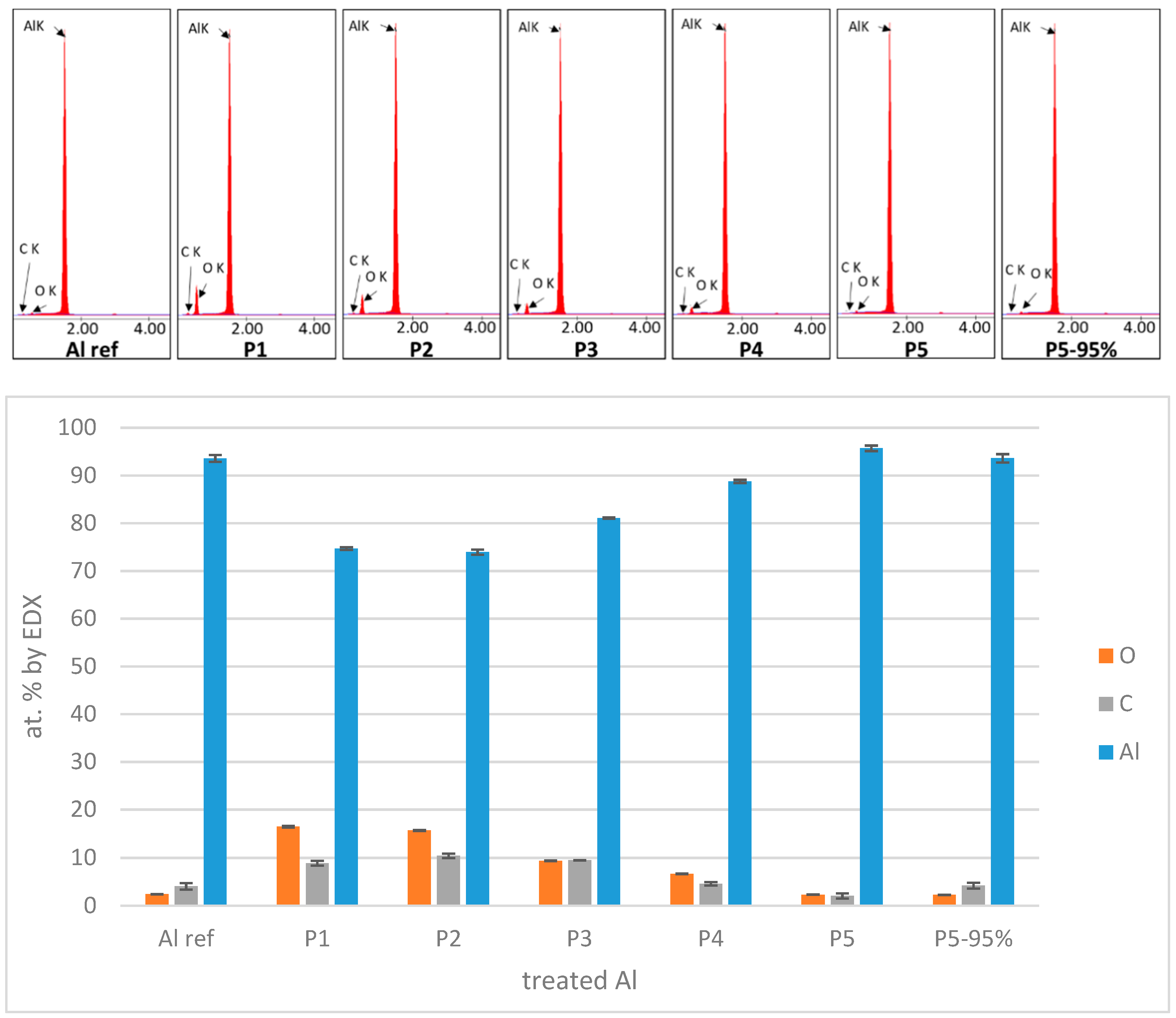
2.7. Energy-Dispersive X-Ray Spectroscopy (EDX)
EDX spectra were obtained in the SEM with an EDAX GENESIS XM 4i energy-dispersive X-ray spectrometer (EDX, Mahwah, NJ, USA). The analytical distance used for X-ray measurement was 10 mm, which corresponded to a take-off angle of 35°. The measurement was performed at a pressure of 3 × 10⁻⁴ Pa (water vapor) and an accelerating voltage of 15 kV. A 0.15 × 0.13 mm2 area was scanned and an average spectrum was obtained on the whole area. The elemental composition is calculated from this spectrum, assuming the sample is only composed of aluminum, oxygen, and carbon. This assumption is made after observing the whole EDX spectra and identifying the peaks exhibiting a significant height.
2.8. Surface Topography
Surface profile was obtained for the ablated Al by means of a P17 (KLA Tencor, Milpitas, CA, USA) mechanical profilometer equipment with a scanning load of 0.5 mg. Measurements were performed by using acquisition rate of 50 Hz, a scanning speed of 20 µm/s, and a scanning length of 2 mm, resulting in a scanning time of 100 s and 5000 measured points. Six regions of 1 cm
2 area were ablated on an Al sample. Four measurements were performed on each region; two along the axis of applied pulling forces during shear testing, and two perpendicular to it. The roughness profile was calculated with a cut-off length of 0.25 mm. Roughness parameters
Rq (average quadratic height or “root-mean-square” roughness) and
Rdq (average quadratic slope) were calculated following ISO 4287 [
26], and their average value is reported.
Similar measurements performed on PA sample show that its average quadratic height (
Rq) is close to 40 nm. Raw or ablated aluminum exhibit
Rq values close to 400 nm or in the range of 0.9–6 µm, respectively. It shows that the PA is very smooth compared to ablated aluminum and that the schematic drawing in
Figure 3b is a reasonable representation of “real life” conditions.
2.9. Laser Flash Analysis (LFA)
In order to prepare ablated samples for LFA, they were cut to 1 cm
2 squared geometry, using an Accutom 50 dicing tool from Struers (Ballerup, Denmark). Then, ablated samples were arranged in layered configuration, together with a 1 mm thick polished aluminum sample with the same dimensions as the ablated ones, as shown in
Figure 4. Samples were coated on both external faces using Graphit 33 spray from Kontakt Chemie (Iffezheim, Germany) containing 1–5
w/
w % of graphite powder in order to have a consistent absorbance to the laser beam and consistent emissivity to the IR detector.
Laser flash analysis (LFA) test was performed by a Netzsch LFA 457 Microflash machine (Selb, Germany) at room temperature. A single flash (0.5 ms) from Nd-Yag laser was irradiated on the untreated surface of the ablated aluminum sample, as illustrated in
Figure 4. The LFA chamber was filled with dry argon gas during the experimentation in order to reduce the influence of moisture on the measurement of the thermal properties. An infrared detector (InSb photodiode) was used to monitor the temperature transient at the back face. The output voltage of the laser was fixed at 1922 V for all experiments. A duration of 60 ms was used for the acquisition time of the IR detector.
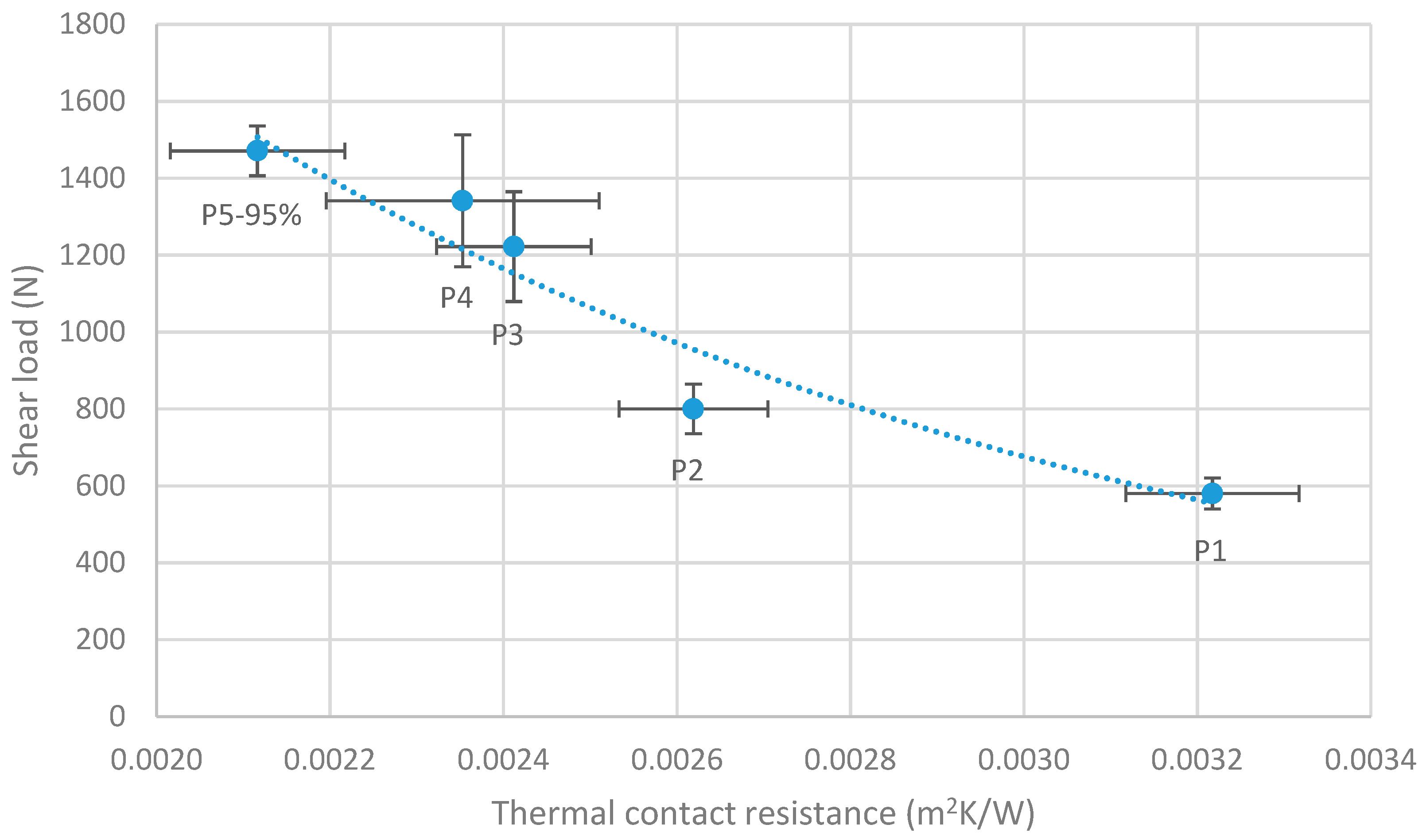
Layered configuration (see
Figure 4) was used in order to calculate the TCR generated by the particular geometry of the rough ablated surface in contact with a flat surface [
27]. It is difficult to calculate the exact TCR between PA and Al by using LFA with such layered configuration, due to experimental challenges resulting from the low thermal conductance of PA. Therefore, the rough ablated aluminum is brought into contact with another flat aluminum sample. Thermal diffusivity of the layered system is evaluated from the measurement of temperature increase as a function of time at the back face of the polished aluminum, i.e., the side facing the IR sensor. Then, the density, thickness, thermal diffusivity, and specific heat of both materials were predefined to that of pure aluminum, kept constant for all tested samples, and used to calculate the TCR based on the algorithm developed by Hartmann et al. [
28].
4. Discussion
The lower mechanical resistance of the joint for untreated (reference, only ethanol cleaning) aluminum compared to laser-ablated samples is easily linked to the different surface chemistry. More precisely, laser ablation is responsible to a lower level of carbon contamination and the formation of a relatively thick oxide layer on aluminum. This certainly creates a strong interaction with molten PA during welding, resulting in cohesive failure mode. This is not the case for reference aluminum, which is responsible for the observation of areas of adhesive failure at the interface, thereby reducing the joint resistance.
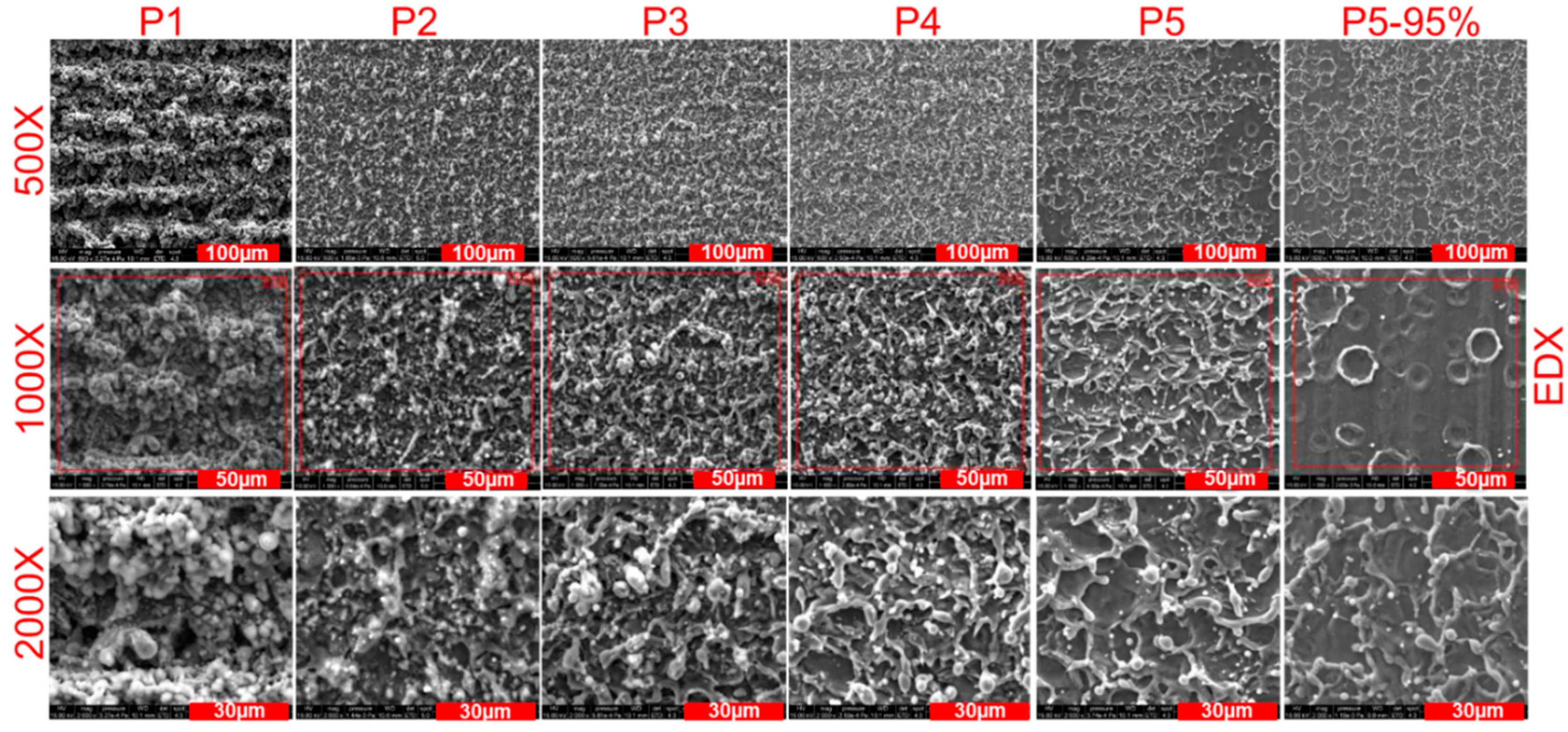
The difference in joint resistance between laser-ablation conditions clearly comes from a difference in joint area, as stated in 3.1. However, this difference in joint area is difficult to explain. When surface chemistry (as evaluated by XPS) is considered, the only correlation that can be observed is a slight increase of carbon content and a slight decrease of oxygen content from P1 to P5-95, i.e., when shear load increases. An increase in carbon content at the aluminum surface is expected to weaken the interactions at the interface between aluminum and PA and makes the joint weaker. This is contradictory to what is actually observed, in particular if it is also mentioned that failure for ablated samples occurs in PA (cohesive failure), i.e., adhesion at the interface is certainly not responsible for the failure of the assembly.
Interestingly, two good correlations between ablated aluminum properties and shear load are observed. The first one is the decrease of the oxygen concentration, as evaluated by EDX, when shear load increases, and the second is the decrease of Rq/Rdq ratio when shear load increases.
The inverse correlation (Pearson coefficient
r = −0.98) between EDX oxygen concentration and shear load could probably be explained by a different thermal behavior of the aluminum sample as a function of its content of oxide or hydroxide relatively to metal aluminum. For instance, if it is hypothesized that aluminum oxide is more stable than hydroxide and that it is formed as a layer close to the surface of aluminum, then the aluminum sample can be considered as a two-layer system: metal aluminum in the bulk and aluminum oxide layer at the surface. Since the thermal diffusivity of aluminum oxide (12 mm
2/s) is lower than pure aluminum (94 mm
2/s) at 300 K [
31], this means that a thicker aluminum oxide layer would act as a larger thermal insulator for the transmission of heat to PA during welding. Thus, an increase in oxygen concentration would result in a decrease in volume of molten polymer during welding, leading to a smaller joint area and a decline in the joint’s resistance to failure.
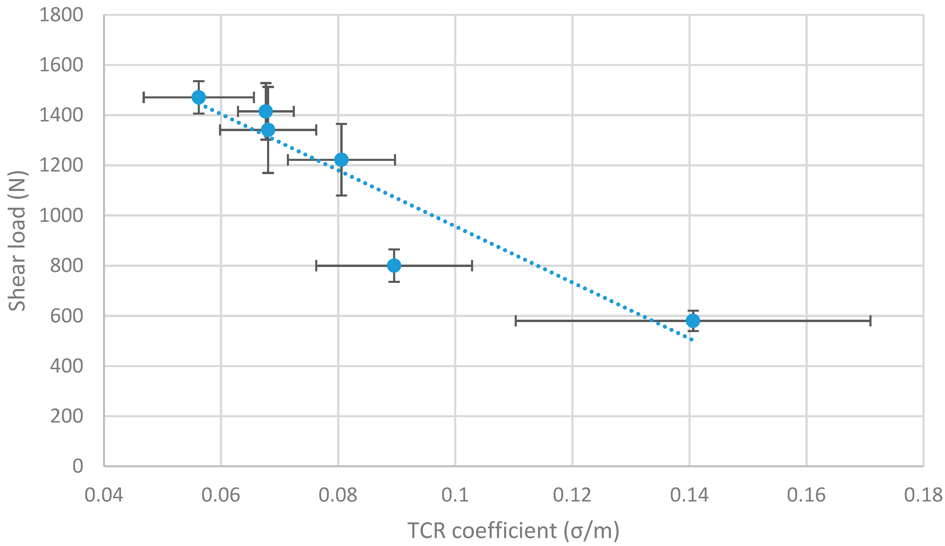
Otherwise, the inverse correlation between the
Rq/
Rdq ratio and shear load (Pearson’s correlation
r = −0.93) has to be interpreted in the light of Equation (1), which links the thermal contact resistance and the σ/m ratio as a surface topography characteristic. In terms of phenomena, it means that, when thermal conduction across a “rough interface” (see
Figure 3b) is governed by the area of microcontacts, the thermal contact resistance (TCR) increases as the area of microcontacts decreases. A lower value of
Rq/
Rdq ratio leads to a lower value of TCR, meaning that a greater heat flow is conducted across the interface. This leads to the melting of a greater volume of PA during welding, which results in a larger joint and a larger shear load. Furthermore, the fact that TCR evaluated by LFA experiments following Hartmann’s method is also well correlated to shear load makes these arguments stronger.
Both phenomena (thermal insulation by aluminum oxide and change of TCR by means of different topography) convincingly explain the increase in shear load from P1 to P5-95. Nevertheless, the authors are currently not able to quantify which phenomenon has the larger effect on this increase, or if one of the two phenomena shall be neglected. Further investigations shall be necessary to answer this question.
Moreover, the correlation between topography and shear load explains why, a posteriori, no correlation was found between the
Ra topography value (which is strongly correlated to
Rq value) and shear load in our former article [
5]. In such a case, the critical characteristic of the surface topography is its morphology of peaks, evaluated by
Rq/
Rdq ratio, and not its amplitude, which is evaluated by
Ra or
Rq.
5. Conclusions
The link between the aluminum surface characteristics after laser ablation and the shear resistance of dissimilar joints formed by laser welding of ablated aluminum with polyamide was investigated. It is observed that shear load at failure of the joint depends on the joint area demonstrating constant joint strength regardless of the ablation parameters. Good correlations between surface characteristics and shear load lead us to make two possible assumptions for explaining the reduction in joint area.
First, it is observed that laser ablation leads to a significant increase of oxygen content in the first micrometers (in depth) of aluminum surface. This might be responsible for a reduction of thermal conduction in the oxygen-rich volume (formation of aluminum oxide/hydroxide), which in turn reduces the quantity of heat transmitted to melt PA during welding.
Second, it is observed that the different topography characteristics obtained after laser ablation of aluminum exhibit different morphology of peaks, which might in turn influence the thermal contact resistance (TCR) between the rough aluminum and the flat PA during welding.
Experimental evaluation of TCR by LFA confirms that thermal-transfer phenomena are probably responsible of changes in shear-load resistance.
This article shed light on the prominence of interfacial thermal-transfer phenomena in the quality of joints obtained by laser welding of a rough ablated aluminum with a polymer.

 ,
, 


