Review

A Review on Micropitting Studies of Steel Gears

State Key Laboratory of Mechanical Transmissions, Chongqing University, Chongqing 400030, China
*
Author to whom correspondence should be addressed.
Coatings 2019, 9(1), 42; https://doi.org/10.3390/coatings9010042
Submission received: 14 November 2018 / Revised: 8 January 2019 / Accepted: 9 January 2019 / Published: 14 January 2019
(This article belongs to the Special Issue Tribology and Surface Engineering)

Abstract

:
With the mounting application of carburized or case-hardening gears and higher requirements of heavy-load, high-speed in mechanical systems such as wind turbines, helicopters, ships, etc., contact fatigue issues of gears are becoming more preponderant. Recently, significant improvements have been made on the gear manufacturing process to control subsurface-initiated failures, hence, gear surface-initiated damages, such as micropitting, should be given more attention. The diversity of the influence factors, including gear materials, surface topographies, lubrication properties, working conditions, etc., are necessary to be taken into account when analyzing gear micropitting behaviors. Although remarkable developments in micropitting studies have been achieved recently by many researchers and engineers on both theoretical and experimental fields, large amounts of investigations are yet to be further launched to thoroughly understand the micropitting mechanism. This work reviews recent relevant studies on the micropitting of steel gears, especially the competitive phenomenon that occurs among several contact fatigue failure modes when considering gear tooth surface wear evolution. Meanwhile, the corresponding recent research results about gear micropitting issues obtained by the authors are also displayed for more detailed explanations.

1. Introduction

Micropitting—also known as peeling, superficial spalling or grey staining—is a surface-initiated fatigue phenomenon occurring during the gear meshing process between interacting surfaces in which a cluster of micropits presents a grey-colored appearance. Compared to classical macropitting which occurs on the nominal Hertzian contact zone and can be identified with the naked eyes, the dimension of the gear micropits can span no more than tens of microns in depth and width along the tooth profile [1], while its length along the axial direction can generally reach 100 μm [2]. As the extensive application of carburized or other case-hardening gears made on the suppression of the subsurface initiate failures, micropitting tends to draw more attention as it can significantly restrict the fatigue lives and reliabilities of the relative mechanical systems [3]. Actually, micropitting is not a instantaneous catastrophic failure mode, but it may lead to vibrations, noises and misalignments, or even contribute to the appearance of other failure modes including pitting, spalling, scuffing and tooth breakage. Höhn et al. [4] stated in 1996 that micropitting had become the most limiting factor of gear behaviors. The National Renewable Energy Laboratory (NREL), Golden, CO, USA, started a gearbox reliability project and hosted a wind turbine micropitting workshop, which was held at the National Wind Technology Center in Boulder, CO, USA, on April 2009 [5]. Just two years later, the NREL reported on the correlation between surface roughness and micropitting at the “Wind Turbine Tribology Seminar”, and the effect of the superfinishing technique was emphasized [6]. The malfunctions and accidents on wind turbine gears caused by micropitting in operation are shown in Figure 1.
Micropitting often starts during the running-in stage (approximately 105 to 106 loading cycles) [7]. As revealed in the field operation, micropitting is often observed near the tooth dedendum, whereas there are also cases in which micropits are found in both the addendum and the dedendum (probably including the pitch line or along the tooth tip). Brandão et al. [8] developed a numerical model of surface-initiated failures and then verified it by applying an actual micropitting test on the carburized gears [9]. The results clearly showed that micropitting could be observed between the pitch line region and the tooth root after the loading period. Additionally, Martins et al. [7] also implemented gear micropitting tests to understand the roughness evolution and micropitting initiation. They found that the occurrence position of each micropit could be significantly affected by tooth surface texture characteristics. The micropits could even be generated on the gear surface roughness valleys, which was resulted from the roughness distribution characteristic of the counter surface.
It is well established that different types of gears show distinguished micropitting resistances. Errichello [5] from the NREL, concluded that helical gears are more appropriate for the micropitting tests than spur gears because they have less vibration and a lower transmission error. Besides, helical gears are less sensitive to profile changes and could operate much more smoothly, leading to the better quality of the fatigue test results. The investigation completed by the British Mechanical Power Transmissions Association found that helical gears produced by case-carburized 16MnCr5 or EN36 steels could give a better micropitting resistance than spur gears [10]. Figure 2 displays the reproduced micropitting damages found on gear tooth flanks of both helical and spur gears after the experiments conducted by the Newcastle University, UK.
It is now generally recognized that micropitting is not only a mechanical or physical problem, but also a chemical problem [10]. In principle, within the nominal contact zone, lubricants will chemically react with surfaces and may subsequently generate stress corrosion cracking, etching or a reaction layer [10]. Winter et al. [11] found that the micropitting resistance would be enhanced by using lubricants containing additives based on sulfurated and phosphorous compounds. Brechot et al. [12] stated that the application of anti-wear (AW) and extreme pressure (EP) additives could prevent scuffing or wear but might promote the micropitting process. Sun et al. [13] investigated the tribo-electrochemical behavior of AISI 304 austenitic stainless steel in a 0.5 M NaCl solution at an anodic potential of 70 mV (SCE) under controlled sliding and electrochemical conditions. The results indicated that the micropits formation was determined by the combined effects of contact load, contact frequency and sliding time.
The contact fatigue performance in lubricated Hertzian contacts has been studied since decades ago by Way [14], Dowson [15], and other researchers [16,17,18]. With the view of quantifying different lubrication conditions, an important relevant parameter was defined as the specific lubricant film thickness λ, namely the lambda ratio, by Tallian [19]:
λ = h 0 R q   ( R q = R q 1 2 + R q 2 2 )
where h0 means the lubricant film thickness with the assumption that the contact surface is smooth, Rq is called the combined root-mean-square (RMS) (certainly, Rq here can be replaced by the effective arithmetic mean roughness value Ra [20]), R q 1 ,   R q 2 can be regarded as the RMS values of the two contact tooth surface roughness. Micropitting is remarkably influenced by the specific lubricant film thickness λ [21]. As recorded in international technique report ISO/TR 15144:2010 [20], a safety factor Sλ based on the specific lubricant film thickness λ is also introduced to represent the micropitting load capacity:
S λ = λ min λ p S λ ,   min
where λmin denotes the minimum specific lubricant film thickness in the contact area, λp stands for the permissible specific lubricant film thickness, Sλ,min represents the minimum required safety factor. When Sλ ˂ 1, a high risk of micropitting is recommended; when 1 ˂ Sλ ˂ 2, a moderate micropitting risk is recommended; when Sλ > 2, a low micropitting risk is recommended [22,23]. Long et al. [24] from the University of Sheffield, South Yorkshire, UK, carried out an investigation on the influence of load variation on gear tooth surface micropitting based on ISO/TR 15144:2010 [20]. Al-Tubi et al. [25] from the same research group studied the gear micropitting initiation and propagation under varying loading conditions based on the ISO/TR 15144:2010 and the revised version ISO/TR 15144:2014 [26].
Although many investigations have been implemented on the gear micropitting issues, and great progressions have been achieved by many researchers and engineers, the detailed mechanisms of micropitting crack initiation and propagation still remain unclear. The future research and real industrial challenges are still severe until micropitting can be well monitored, detected, prevented, and the micropitting mechanism, together with the correlation with other failure modes on gears, could be further explored. Several aspects of the micropitting analysis, such as the thermal effect, the plastic deformation [27], phase transformation, gear types, etc., also need to be persistently promoted.
For the purpose of further understanding, the gear micropitting mechanism and, consequently, efficiently controlling the occurrence of micropitting in the real gear industry, plenty of studies are reviewed in this work to illustrate the steel gear micropitting phenomenon from various aspects. With the consideration of the wear process, a numerical model incorporating material mechanical properties, residual stress gradient and the measured surface roughness of a wind turbine gear pair were developed under the elastohydrodynamic lubrication (EHL) condition by the authors in order to explore the wear effect on the competitive mechanism between micropitting and pitting during the cycling loading period, which could help lead to a relative in-depth comprehension of micropitting.

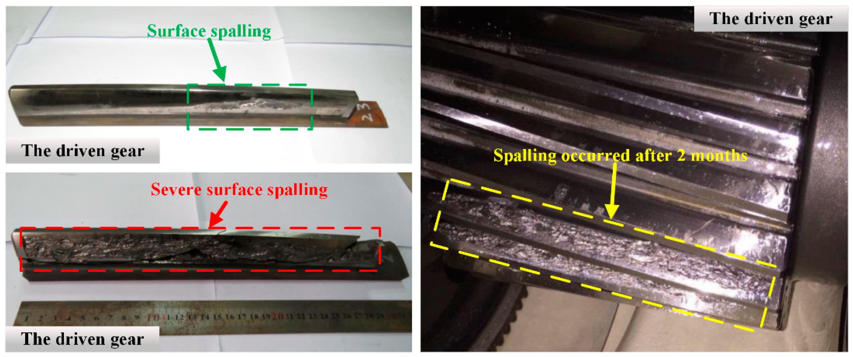
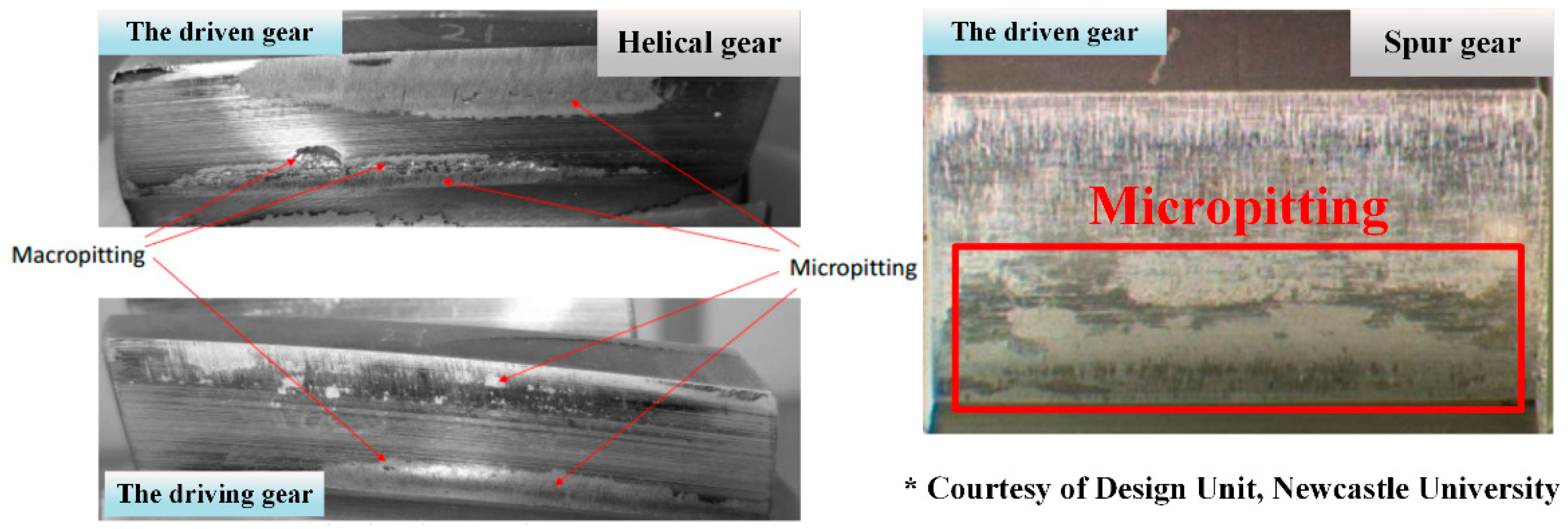
2. Some Influence Factors on Gear Micropitting

Based on the above discussions, there are numerous factors that can affect the micropitting phenomena of gear operations. For example, Olia et al. [1] designed a factorial experiment using a twin disc machine for the purpose of assessing the influence of seven factors, namely the gear steel material, lubricant properties, surface finish, load, thermal effect, speed, and slide-roll ratio, on the micropitting initiation and propagation processes. The results could be summarized as follows: the load had the biggest effect on micropitting initiation, and micropitting propagation could be dramatically impacted by the sliding/rolling condition. Therefore, this section summarizes the relative studies on the influence factors of gear micropitting made by the authors and the other researchers.

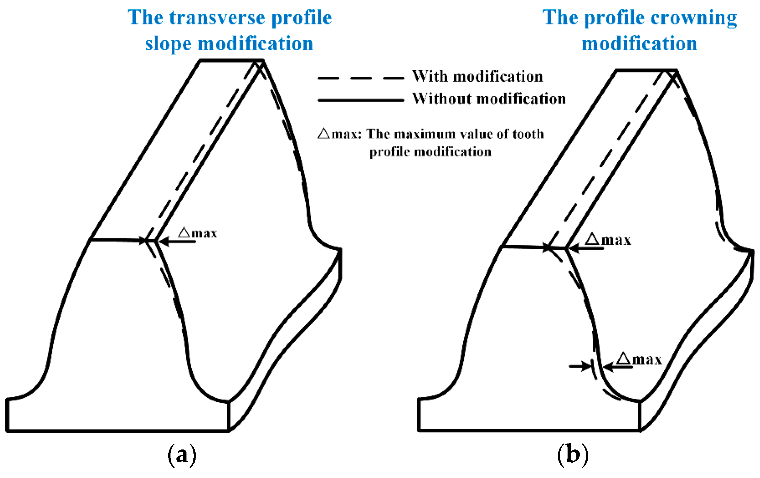
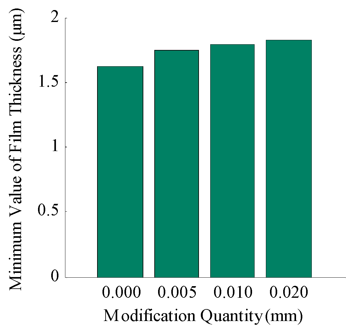
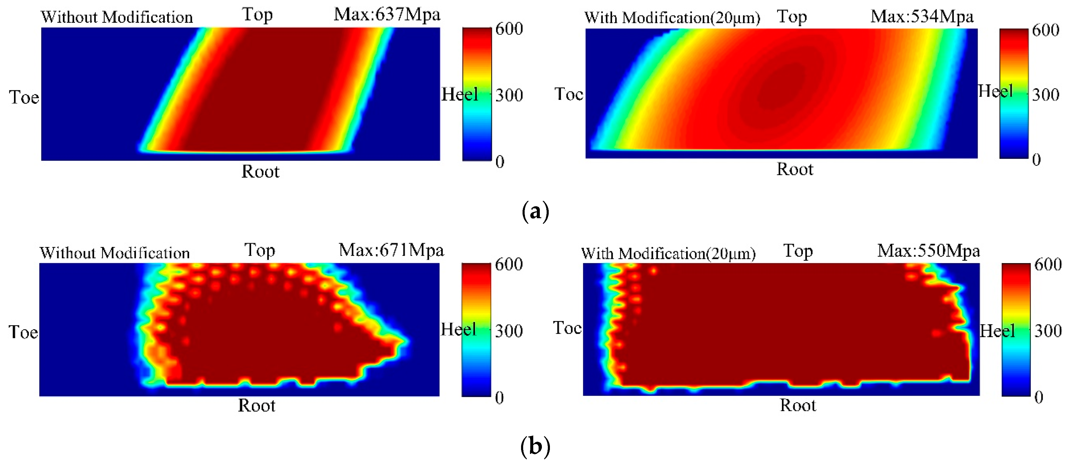
2.1. Gear Materials and Macroscopic Geometries

As revealed by various experimental observations [28,29,30], the difference of gear steel materials and the heat treatment process could generate distinguished micropitting resistances. As reported in the Reference [31], high strength austempered ductile iron gears were gradually accepted due to the low production cost, the eventual noise and vibration reduction, and the self-lubricant properties through graphite nodules, resulting in remarkable gear tooth flank capacity. Moreover, the diversity of surface treatments such as carburizing, nitriding, case-hardening, etc. can improve the gear surface fatigue performances by modifying the material properties or forming a hardened layer over the gear substrate.
Wilkinson et al. [32] from the Imperial College London, London, UK, conducted gear tests on different gear materials for micropitting damage. According to the results, carburized AISI M50NiL steel shows no improvement over conventional carburized 4%NiCrMo steel, but the carburized and subsequently nitrided AISI M5ONiL steel could give a substantial improvement. Metallographic examination on a number of micropitted gears was conducted by Olia et al. [33] and they found that the initiation and propagation of cracks leading to the formation of micropits were related to the phase transformations induced by the contact fatigue process. The micropitting propagation rate was obviously larger for the gear steel in which the martensite decay was more pronounced. Le et al. [34] performed experiments on gas nitride gears through a twin-disc machine; the conclusions could be summarized as the fact that despite the equivalent hardness and compressive residual stress gradients, nitrided layers with thin grains and cementite filaments were more resistant to micropitting than coarse microstructure layers. Moreover, Tobie et al. [35] from the Forschungsstelle für Zahnräder und Getriebebau (FZG), Garching bei München, Germany, tried to optimize the carburized gear performance through alloying modification. The conclusion could be summarized as the fact that the gears made of modified 20MnCr5 presented a remarkable lower sensitivity to micropitting than the gears made of modified 20CrMo5. However, more experiments should be implemented on various types of alloying modification techniques to form a universal method. Roy et al. [36] studied the influence of retained austenite (RA) on the micropitting of carburized AISI 8620 steel under the boundary lubrication state. Three levels of RA% were chosen in the tests, namely 0% (low RA), 15% (medium RA) and 70% (high RA), to guarantee the experimental efficiency. With the application of the X-ray diffraction method, the 70% RA sample was proved to present the best micropitting life. This indicated that higher levels of RA% should be guaranteed by appropriate heat treatments, in order to ensure a stable amount RA% remains after the phase transformation for the sake of the micropitting life improvement. However, the effect of RA level on the comprehensive contact fatigue has not been fully revealed.
The gear geometry properties can also have nonnegligible effects on micropitting resistance. In the former work reported in Forschungsvereinigung Antriebstechnik e.V. (FVA, Research Association for Drive Technology) research project 259/I (1994–1998), the influences of gear geometry and gear size on micropitting were discussed in detail. For instance, the diagram of a beveloid gear tooth with transverse profile slope modification and profile crowning modification is schematically illustrated in Figure 3. Several studies concerning the gear geometry or gear tooth modification are presented as follows.
Kissling [38] outlined that anti-micropitting capacity could be improved through macrogeometry optimization such as gear tooth profile modifications. Predki et al. [39] studied the effect of gear tooth flank modification on micropitting and concluded that the variation of tip relief forms and amounts could obviously impact the micropitting resistance. Besides, the increase of the profile modification amount would result in a lower profile form deviation, except some cases of very large modification amounts. Li [40] studied the effect of the angular misalignment on the micropitting resistance of a spur gear pair made of AISI 8620 steel. Numerical results showed that an optimized crown magnitude, which was dependent on both the input torque and the misalignment amount of the spur gear pair, should be determined for increasing the micropitting life. Weber et al. [41] from the FZG investigated the influence of the increased pressure angle on the flank surface capacity of gears by comparing the reference pressure angle (20°) and a modified tooth pressure angle (28°). Tests and calculations both indicated that when applying the same nominal contact stresses at the pitch point, the pressure angle modification might not have an evident impact on the micro-pitting load capacity. However, more experiments need to be designed on groups of different gear pressure angles to obtain higher relatively reliable results.
It is deserved to be mentioned that the effects of gear modification techniques on the gear contact characteristics have also been investigated by the author’s team [42]. Liu et al. [43] proposed a mathematical concave modification model for the beveloid gear tooth surfaces with crossed axes. The loaded tooth contact analysis (LTCA) and the theoretical tooth contact analysis (TCA) were performed to the analytical contact patterns. In this work, four cases were presented and compared with each other: Case 1) Pinion with profile crowning modification and gear with profile concave modification; Case 2) Pinion without modification and gear with lead concave modification; Case 3) Both pinion and gear with lead concave modifications; Case 4) Pinion with combined concave modification and gear with combined crowning modification. The modification methods of all these four cases could enlarge the contact area, decreased the maximum value of the contact stress and increased the minimum film thickness compared with the case without any modification. That indicated the gear surface capacity such as micropitting resistance could be amplified by applying appropriate tooth modifications. The minimum film thickness, the contact pattern of TCA with and without modification, the contact pattern of LTCA with and without the modification of Case 4 (Pinion with combined concave modification and gear with combined crowning modification) are depicted in Figure 4 and Figure 5, respectively.

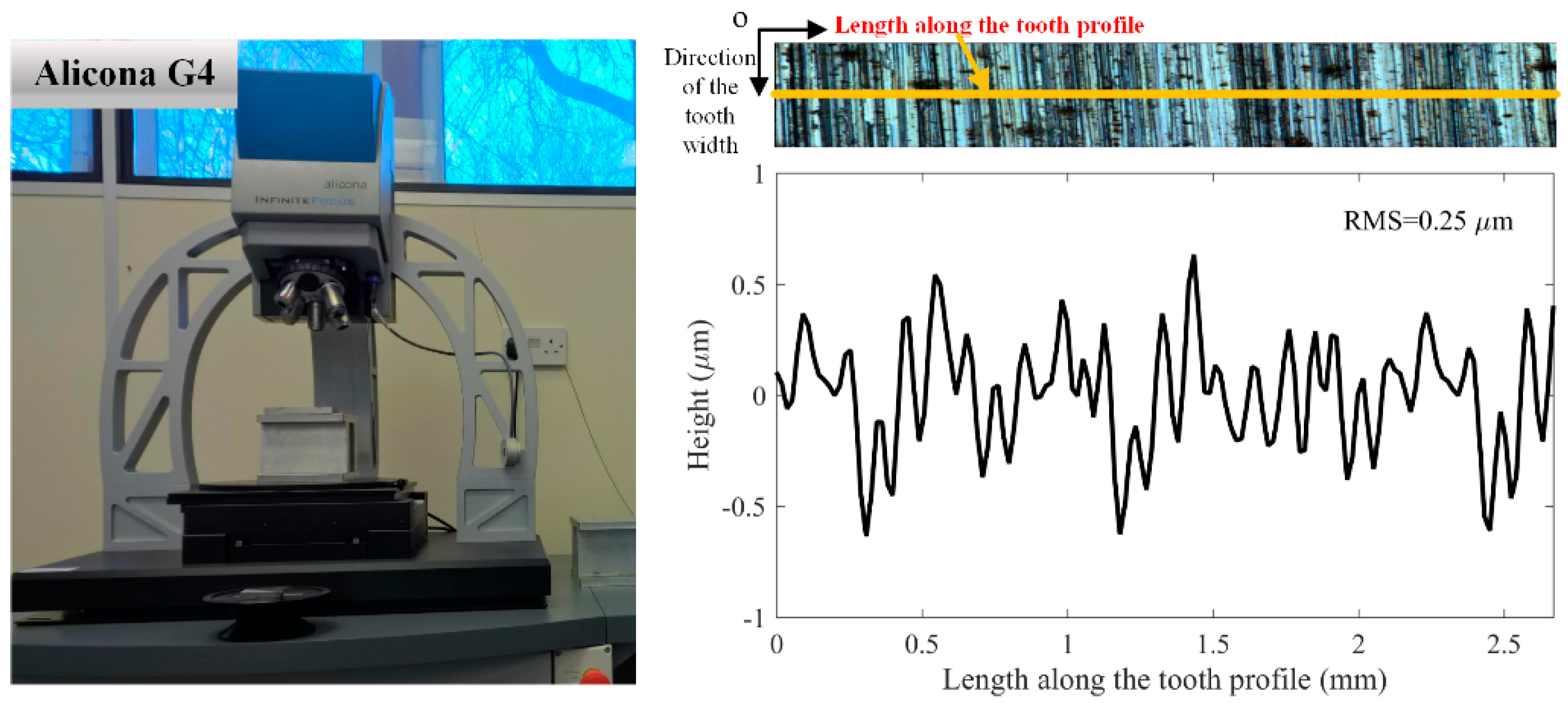
2.2. Gear Surface Microscopic Topographies and Surface Treatments

Micropitting phenomena are closely associated with surface topography effects in high-duty hardened gears finished by grinding [44]. Berthe et al. [16] pointed out that surface roughness could be the driving force of the micropitting phenomenon, which is widely accepted. Therefore, various investigations have been conducted by many researchers to explore the effect of gear surface topography on micropitting [45,46]. Although the effect of surface topography on contact fatigue is often discussed under the lubrication state, the effects of lubrication properties (including the lubricant types, the additives, contaminates, etc.) are still expounded in the following section for a clearer explanation.
Winkelmann [6] from the NREL reported on the correlation between the surface roughness and micropitting, suggesting that the micropitting could be formed along the surface roughness asperities. Evans et al. [47] from Cardiff University, Cardiff, UK, predicted the micropitting damage through a micro-EHL model considering the measured surface roughness. The micropitting tests were carried out on helical gears for validation. In their work, the micropitting damages of generation-grinding and form-grinding gears were also compared, emphasizing the importance of 3D “waviness” on gear micropitting behaviors. Li et al. [48] proposed a primary numerical model considering lubrication and surface topography to predict the gear micropitting life. A year later, they improved the former model [49] and simulated the micropits distributions on the tooth flank. In addition, experiments were planned for the verification of the proposed model. A micropitting severity index (MSI) was defined as the cumulative probability in order to quantify the micropitting damage level. Whereas the effects of wear, case-hardening, residual stress gradient and the plastic deformation were still not considered in their work, which means a relative more comprehensive numerical model of micropitting is necessary to be further developed. Furthermore, Li [50] himself developed another numerical model a year later, which focused on the effect of surface roughness lay directionality on the micropitting of lubricated point contacts. The most severe micropitting damage was observed on the gear surface whose roughness lay was parallel to the rolling direction, while the roughness lay of its counterpart was vertical to the rolling direction. This conclusion has a considerable reference value on gear design and manufacturing processes, especially grinding and superfinishing. AL-Mayali et al. [51] investigated theoretically and experimentally the micropitting initiation based on the real surface topography under the micro-EHL regime. Both the numerical and experimental results showed that the micropits formed during the running-in stage (within 105 cycles) since the initial surface roughness asperities were significant. Mallipeddi et al. [52] compared the micropitting resistance of gears processed by grinding, honing and superfinishing. They concluded that the surface asperities could have a tremendous influence on the surface-initiated fatigue such as micropitting. The micropitting initiation could be significantly affected by the running-in load level, but only for rough surfaces.
Furthermore, the authors have numerically studied the effects of gear surface roughness on the RCF issues under the EHL condition considering the measured hardness and residual stress gradients, following the flow diagram shown in Figure 6.
The carburized gear pair sample stems from the intermediate parallel stage of a 2 MW wind turbine gearbox, which is made of 18CrNiMo7-6. The main gear parameters are listed in Table 1. The carburizing, tempering, finishing and grinding processes were all adopted to obtain better material properties and higher failure resistance of this large-scale, heavy-load gear pair. The initial gear surface roughness, processed by the generating grinding method, was measured through a high-resolution optical device (Alicona G4) along the tooth flank profile. The initial roughness RMS value is around 0.25 μm. Figure 7 shows the optical measurement device and the initial surface roughness profile along the rolling direction.
The EHL theory was applied to predict the contact pressure distribution, addressing the effects of the surface roughness. The stress histories of interesting material points during complete contact loading cycles were calculated by exploring the discrete-concrete, fast Fourier transformation (DC-FFT) method [53]. Detailed EHL modeling and stresses calculation strategies can be referred to the authors’ former work [54,55,56]. Subsequently, the Dang Van multiaxial fatigue criterion [57] shown below was applied to evaluate the multiaxial stress state during the contact, and the residual stress measured by the X-ray diffraction method could also be considered in the calculation.
τ DangVan ( t ) = τ max ( t ) + α D [ σ H ,   load ( t ) + σ H ,   Residual ( t ) ]
where τDang Van is the Dang Van equivalent stress which can be deduced from the multiaxial stress history during the loading process, τmax is the maximum shear stress, σH,load means the hydrostatic stress caused by applied load, σH,Residual represents the residual stress term. αD is the material parameter which can be calculated through the hardness data measured by the Vickers hardness test [58]. The measured hardness and the residual stress gradients of the mentioned gear sample can be seen in Figure 8. It is deserved to be mentioned that the maximum amplitude of the induced compressive residual stress may not appear at surface [59,60], thus the effect of residual stress on micropitting was not addressed.
Based on the Dang Van criterion, a concept called the index of contact fatigue failure risk could be calculated as follows, in order to represent the failure possibility during the loading cycles:
R ( z ) = τ Dang Van ( z ) τ 1 ( z )
where R is the risk of gear contact fatigue failure, τ−1 is the fully reversed torsion fatigue limit [61] which can be deduced from the hardness gradient, as expressed in Equation (5) [62]; and certainly, Z represents the depth.
{ τ 1 ( z ) = 0.773 HV ( z ) HV ( z ) 2 / 3170     ( MPa ) σ 1 ( z ) = τ 1 ( z ) / 0.577     ( MPa )
As for the results, Figure 9 illustrates the risk of the contact fatigue along the depth at the position where the maximum τmax is at peak value during the complete contact loading cycle within the calculation domain at the pitch point with different asperity conditions [63]. It reflects the fact that the increase of the surface roughness RMS makes the maximum index of the failure risk significantly rise, and its occurrence position gradually becomes shallower, reaching a depth of about 0.05 mm when the RMS rises to 0.5 μm, where the micropitting is apparently more likely to occur.
Surface treatments such as grinding and superfinishing were proven to be effective on modifying the surface topographies positively, subsequently reducing the surface-initiated failure risk. As reported in Reference [6], micropitting could even be eliminated by superfinishing. Furthermore, superfinishing can also be applied to improve the lubricant life and cleanliness, which generates a higher component fatigue life.
Karpuschewski et al. [64] concluded two main reasons for gear finishing, (1) surface quality improvement and form error reduction, and (2) flank modification and surface integrity improvement. In order to quantify the effect of surface roughness on gear surface fatigue life, Krantz et al. [65] applied a near-mirror finish on AISI 9310 steel gears, the test data was also compared with the National Aeronautics and Space Administration (NASA) Glenn gear fatigue database. The results indicated that the superfinishing could extraordinarily reduce the surface roughness influence by making the roughness value Ra along the involute direction lower to around 0.1 μm, and subsequently leading to a higher micropitting resistance. Besides, the fatigue lives of gears with superfinishing were about 4 times greater than that of gears with ground teeth. Winkelmann et al. [66] mentioned that the Isotropic Superfinish (ISF) gears during the fatigue tests never showed any sign of micropitting phenomena (micropitting coverage was 0%, profile form deviation was 0 μm) nor reached any of the specified failure criteria compared to the baseline gears with a lower micropitting resistance. From the gear micropitting experiments carried out by Rabaso et al. [67], a conclusion could be made that the ground gear surfaces obviously showed better micropitting phenomena than the turned gear surfaces. Shaikh et al. [68] applied electrochemical honing on bevel gears and found that within an optimized finishing time of 2 min, an obvious improvement in the surface finish and form accuracy were observed. Meanwhile, the gear surface integrity was improved and the surface failure resistance was enhanced. Ronkainen et al. [69] studied the influence of a surface finish under the high-load gear contacts. The results revealed that micropitting could be prohibited through polishing the gear surfaces by reducing approximately 27% of the friction coefficient.
Besides grinding and superfinishing, the effects of other surface treatments such as shot peening [70] and coating [69,71] are also widely studied, and strides have been made constantly on the understanding of these technologies. The diversity of investigations which focus on the effects of this kind of surface strengthening treatments on the gear micropitting behavior [72] are outlined. Terrin and Meneghetti [73] studied the contact fatigue on both shot-peened and un-peened 17NiCrMo6-4 case-hardening gear steel specimens through a two-disc test rig. No obvious improvement of micropitting resistance was found between the shot-peened and un-peened specimens. However, a contrary conclusion was presented by Pariente and Guagliano [74]. They analyzed the contact fatigue damage of shot peened gears through the X-ray diffraction method and claimed that the shot peening was effective to suppress the micropitting initiation. In addition, a similar conclusion could be drawn from the work of Rabaso et al. [67] mentioned above, in which it was stated that the shot peening was beneficial to the rolling contact fatigue (RCF) resistance. Koenig et al. [75] from the FZG, Germany, summarized the effects of shot peening on the tooth flank load carrying capacity reported in the FVA research project 521 I. Based upon the test results, they developed an extensive calculation method on the surface-initiated damage resistance, and claimed that both the shot peening and superfinishing could allow a positive effect on the gear surface properties, leading to a further increase of the gear tooth surface load capacity. According to the experiments conducted by Qin et al. [76], the ultrasonic nanocrystal surface modification (UNSM) has been proved to be a promising technique for the enhancement of micropitting, wear and pitting resistances of mechanical components such as gears and bearings, making the components surface roughness value Ra less than 0.02 μm.
With respect to the gear coating techniques, Krantz et al. [77] carried out experiments to compare the surface fatigue lives of case-carburized AISI 9310 steel spur gears with and without metal-containing, carbon-based coating. Almost all test coated gears survived from the fatigue failure after 275 million cycles and the coating was proved to be significantly effective to improve the tooth surface capacity. Vetter et al. [78] reviewed the improvements in surface treatments for automotive applications. A conclusion could be made that gear coated with a–C:H:Me (W–C:H) presented an obviously better micropitting resistance and higher load capacity. Martins et al. [79] discussed the effect of multilayer composite surface coatings (molybdenum disulphide/titanium (MoS2/Ti) and carbon/chromium (C/Cr)) on the gear capacity and friction coefficient. Experimental results showed that the load capacity of the coated gears had been highly improved. Bayón et al. [80] studied the gear tribological performance of the newly developed multilayer physical vapor deposition (PVD) coatings, namely Cr/CrN and CrN/ZrCN. They found that the Cr/CrN coating dramatically decreased the micropitting and scuffing damages. Moreover, the CrN/ZrCN coating could improve the wear resistance, especially under extreme pressure conditions. Moorthy and Shaw [81] from the Newcastle University, UK, tried to evaluate the contact fatigue performances of helical gears coated with Balinit C1000, Balinit C*, CrN + IFLM, C6 + IFLM and Nb–S coatings. The results suggested that the Nb–S coated gears have the best overall contact fatigue performance, followed by Balinit C coated gears with minimum micropitting damage. The same research team also compared the micropitting resistance of as-ground gears and gears coated with BALINIT® C and Nb–S coatings [82]. They concluded that both BALINIT® C and Nb–S coated gears possessed better micropitting behaviors by removing localized stress concentration at micro-valleys which presented on as-ground gears. Singh et al. [83] from the Argonne National Laboratory, US, developed a soft H-DLC coating (highly elastic and has a hardness value comparable to that of gear steel substrate) for sliding/rolling gear contact applications, which was proved to be beneficial to components that suffer from micropitting. During the tests, no failure was observed with the coated specimens even after 100 million cycles. As a comparison, the uncoated gear failed after only 32 million cycles. Benedetti et al. [84] investigated the effects of WC/C, WC/C–CrN, and DLC based coatings on lubricated contact behavior. The multi-layer WC/C and WC/CrN based coatings, together with the DLC coating showed a good contact fatigue performance, but these coatings were still unable to prevent the micro-pitting occurrence at the end of the tests.

2.3. Working Conditions

The influences of working conditions on micropitting have been widely investigated, and relative research could be found elsewhere [1,20,26]. This section reviews the studies which concern the effects of the normal load condition, the sliding/rolling condition and the lubrication state on micropitting behavior. Moreover, the corresponding recent results of the authors are presented.

2.3.1. The Normal Load Condition

The crucial influence of load condition on the micropitting has been addressed by many studies [25,85]. Fajdiga et al. [86] proposed a numerical model to simulate the micropitting growth on the tooth flank under boundary lubrication together with rolling and sliding conditions. This model was basically subjected to the normal contact pressure and the frictional forces, and the calculation results corresponded well with the experimental data. Olia and Bull [1] studied the diversity of influence factors on micropitting by experiments, including the normal load effect. They reported that micropitting initiation was mostly controlled by contact pressure and the micropitting propagation process was also mainly affected by the resultant pressure distribution. However, different conclusions of the loading influence on micropitting can be summarized from the diversity of studies. Webster and Norbart [87] reported that increasing applied load would accordingly increase the gear micropitting rate. While Rabaso et al. [67] found that the contact pressure would not impact the material’s resistance to RCF in the range considered (1.5–2.5 GPa). Furthermore, Moallem et al. [88] estimated the micropitting life through the Zaretsky equation and applied the load-sharing concept, and subsequently comparing with the experimental results from the previous literature articles. The results showed that the applied load increased by about 4 times could decrease almost 50% of the micropitting life. Mallipeddi et al. [89] investigated the effect of running-in load state on surface characteristics of ground gears on an FZG rig. They summarized that a high running-in load would increase not only the operating efficiency but also the micropitting resistance. However, no obvious connection between the micropitting and the phase transformation within the gear steel was observed, which was inconsistent with the results obtained in the aforementioned studies. An et al. [90] demonstrated the micropitting occurrence through the Dark and Bright Ratio (DBR) method under different Hertzian contact pressures and developed a novel engineering regression equation to predict the RCF life.
Based upon the same gear sample and influence factors in the numerical model mentioned above, the loading effect was discussed by the authors. Several input working conditions of this parallel stage were chosen from the measured load spectrum, including the low input loading case (input torque = 102,000 N m), the medium loading case (reference input torque = 241,000 N m) and the high loading case (input torque = 363,000 N m), all the input speeds of these three cases were set to be the reference input speed, which is 64.8 rpm as listed in Table 1 for clear comparison. The contact fatigue lives were estimated by applying the Brown–Miller multiaxial criterion [91] modified with the mean stress as shown below; this multiaxial criterion is based on the critical plane criterion:
Δ γ max 2 + Δ ε n 2 = C 1 ( σ f σ m ) E ( 2 N f ) b + C 2 ε f ( 2 N f ) c
where ∆γmax/2 stands for the maximum amplitude of the shear strain, ∆εn/2 refers to the amplitude of the normal strain on the critical plane where the maximum amplitude of the shear strain appears, σm represents the mean of the normal stress on the critical plane; b, c are the fatigue strength index and the ductility index, respectively; C1, C2 are material constants, Nf is the number of cycles of fatigue; σ f , ε f are the axial fatigue strength coefficient and the axial fatigue ductility coefficient, respectively. The schematic diagram of the calculation domain and the critical plane for the Morrow–Brown–Miller multiaxial criterion are shown in Figure 10. Where the calculation domain can be divided into many equally spaced grids for the sake of both the calculation efficiency and accuracy. Parameter θ is the angle between the direction of the normal stress σn and the positive direction of the x-coordinate. With the view to determining the critical plane where the maximum amplitude of the shear strain takes place, all the candidate planes had to be scanned with a 5° step from 0° to 180° at each interested material point within the calculation domain.
Figure 11 shows the contact fatigue lives distributions along the depth calculated based on different input torques with the initial surface roughness. As can be seen clearly, the minimum surface fatigue life decreases from 1.42 × 10⁶ to 2.29 × 10⁵ significantly as the input torque increases. Moreover, the minimum fatigue lives all appear at the positions very near to the gear surface in these three cases, indicating that the micropitting risk may be predominant at this moment. The result implies that larger loading may lead to faster micropitting damage, namely, a shorter micropitting fatigue life, which agrees well with the studies in reference [88].

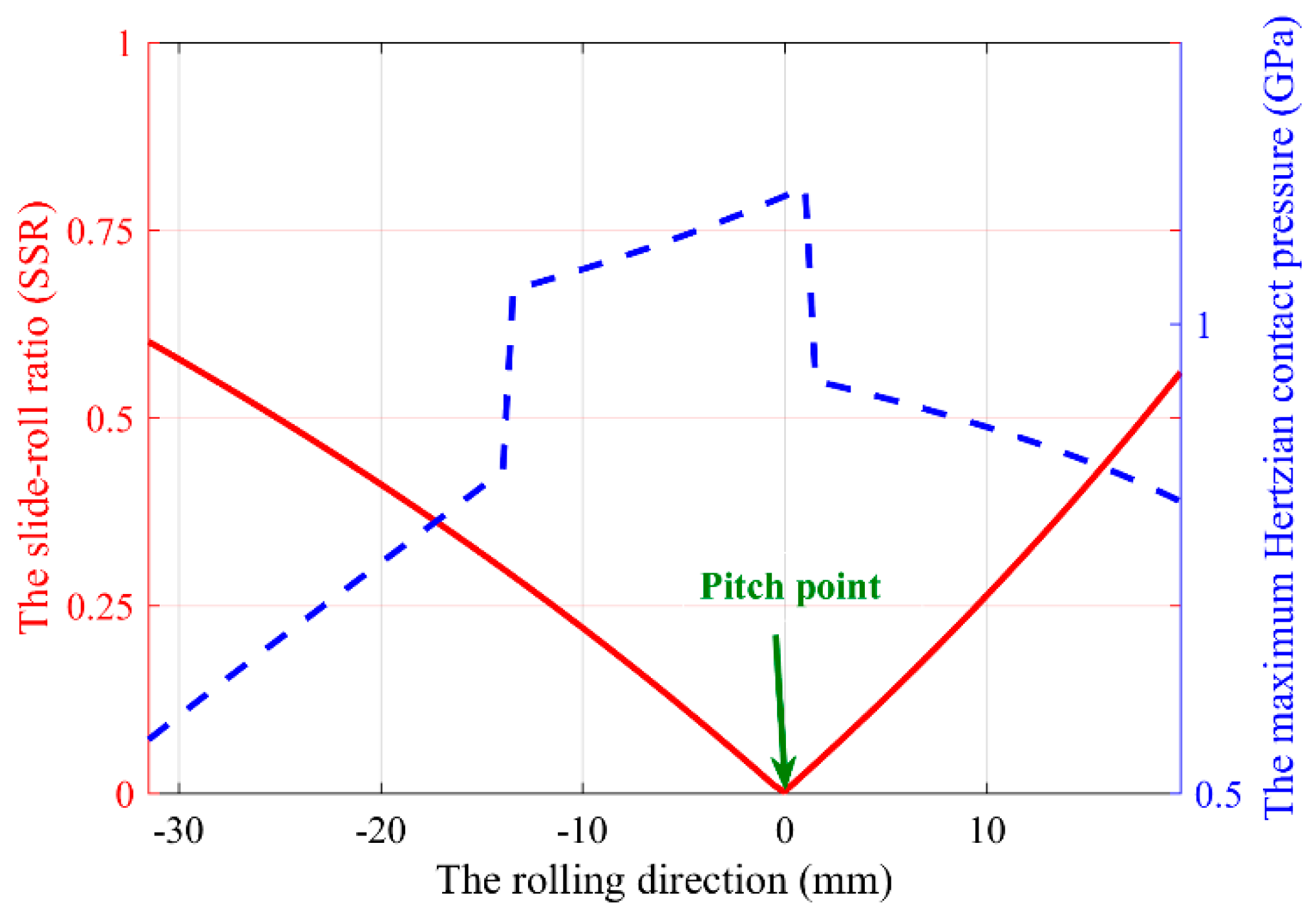
2.3.2. The Sliding/Rolling Condition

The sliding/rolling condition is a general factor of the gear micropitting phenomena, which is being widely explored in many studies [82,92]. According to the work implemented by Olia and Bull [1], speed and slide-roll ratio have the biggest effects on micropitting propagation. Furthermore, the micropitting crack angle and propagation direction could be directly influenced by the sliding/rolling condition [85,93]. Figure 12 schematically presents the correlation between the micropitting crack growth direction and the sliding/rolling condition on the gear tooth flank of the driving and the driven gears.
Speed is one of the main influencing parameters that can be controlled and studied during the gear experiments [88]. Based on Seireg’s research [94], a higher gear speed may result in smaller size and shallower depth of the micropits. Interestingly, this paper also considers the effects of thermal shock, thermal stress cycling, coatings, surface roughness and different surface treatments on the pitting, micropitting and wear behaviors.
The value of the slide-roll ratio (SRR) illustrates the proportion of the sliding effect during the gear contact, which is very crucial to the evaluations of gear surface capacities, such as micropitting, wear and scuffing resistance. A few decades ago, Zhou et al. [95] from the Northwestern University, US, proposed a numerical model for predicting the onset of gear micropits for a given lubrication state under rolling and sliding contacts condition. The calculation results were also verified by experimental data obtained through a two-disk rig. Errichello [96] illustrated that the micropitting crack growth could be affected by the rolling and sliding condition. The micropitting cracks usually grow opposite the sliding direction at the gear tooth surface. From the explanation of Morales-Espejel and Gabelli [94] from the Svenska Kullager-Fabriken (SKF) Engineering and Research Centre, the Netherlands, the surface spalling direction may depend on the friction direction of the sliding-rolling condition, instead of random directions under pure rolling condition. Sanekata et al. [97] reproduced the micropitting caused by RCF on the carburized SCM420 steel under applied SRR of 0%, −20% and −40%. A large number of micropits appears after the RCF tests. The results showed that the angle of microcracks between the initiation and the rolling direction increases as the SRR, as well as the shear strain, increases. Another reference from Morales-Espejel et al. [46] selected three SRR values, 0.05, 0.15, 0.30, in order to emphasize the important role of SRR on the micropitting phenomena. They concluded that the micropitting occurrence position could be affected by the combined effects of SRR, contact pressure and wear phenomenon. The micropits might appear inside the single pair contact region due to the combined effects, rather than the positions where the maximum contact pressure exists, as generally considered. Cen et al. [98] from the University of Leeds, UK, tried to investigate the effect of SRR on the micropitting damage. The test gears were lubricated with Zinc Dialkyl Dithiophosphate (ZDDP) containing lubricants. The results showed that increasing SRR can reduce the micropitting area on the worn surface obviously.
The influence of sliding/rolling condition on the surface-initiated failures can also be reflected in the authors’ recent work. Based on the aforementioned numerical model, the contact analysis and the wear investigation could be launched primarily. The Archard’s wear model is a well-accepted wear prediction method [99,100,101] which is quite appropriate to reveal the influences of contact parameters on the wear process. The general Archard’s wear model of each local material point on one of the interacting surfaces can be formulated as [102]:
d h w d s = k p m
where hw stands for the wear depth, s denotes the sliding distance, pm represents the mean value of the local contact pressure, and the wear coefficient k is chosen to be 1.9 × 10⁻¹⁹ m2 N−1 according to reference [103], where the similar gear steel material after case-hardening is used. Based on the same gear sample introduced in Section 2.2, Figure 13 displays the maximum Hertzian contact pressure pH and the SRR distributions along the LOA [104].
Moreover, Figure 14 presents the estimated wear depths along the line of action (LOA) during the first loading cycle of both the driving and the driven gears [104]. Compared with these two figures, a simple conclusion can be made that the micropitting, wear behaviors and the SRR are interrelated. Apparently, the contact pressure, the sliding/rolling condition and the wear coefficient are the main factors on the surface contact fatigue performance according to the Archard’s wear equation. In this study, the largest wear depth appeared at the lowest point of single tooth contact (LPSTC) of the driven gear.

2.3.3. Lubrication Conditions

The earliest discussion of micropitting in the tribology field appeared in the study by Berthe, et al. [16], and the lubrication condition was generally the main concern of this kind of studies [105]. The micropitting phenomenon is generally analyzed under the mixed or boundary lubrication condition [106,107]. Moreover, the lubricants type [93], the additives [108], and other lubricant properties [109] can have noticeable influences on the contact fatigue behavior. In the following studies, the effect of lubricant types, additives, oil supply condition and the thermal effect on micropitting are outlined.
Different types of the lubricants used in the gear contact can result in a total discrepancy on micropitting damage [110]. The discussion of the effects of lubricant types on micropitting is mainly between the mineral oils and ester oils. According to Martins et al. [31], the direct comparison of biodegradable ester and mineral oils effects on the micropitting of austempered ductile iron gears was performed. The gear micropitting tests were conducted in an FZG test rig using these two types of industrial gear oils samples, and they found that compared to the gears lubricated with mineral oil, the gears lubricated with ester oil possessed a 20% lower cumulative mass loss. Additionally, the micropitting area of these two cases was similar. According to the gear micropitting performed by the same research team [111], still no obvious discrepancy on the micropitting phenomena was found between the carburized gears using the mineral and biodegradable ester gear oils. Cardoso et al. [112] compared the gear micropitting behavior of high-pressure nitriding steel gears which were lubricated with a standard mineral lubricant and two biodegradable esters. The gears with the ester lubricants presented better a micropitting resistance than the gears with the mineral oil. This study may support the applicability of biodegradable ester oils on gear lubrication, mainly when the high micropitting resistance is required.
The lubricants are generally composed of a majority of base oils plus a variety of additives to impart desirable characteristics and the composition of lubricants have been extensively investigated. The properties of the additives can directly influence the fatigue failure resistance of the gear surface. Lainé et al. [113] added a common friction modifier agent, molybdenum bis-diethylhexyl dithio-carbamate (MoDTC), to an oil containing an anti-wear additive (secondary ZDDP) and to a mineral base-stock in order to study the influence of the friction modifier additive on micropitting. The micropitting could be greatly reduced when added with ZDDP, compared to the samples added with MoDTC. Ochoa et al. [114] explored the effects of the different additive types in a polyalphaolefinic low-viscosity base oil, namely a polyalphaolefin PAO6, on the gear micropitting resistance. The results suggested that the extreme pressure (EP) or anti-wear (AW) additives might lead to a greater micropitting damage on the gear surfaces at the running-stage under severe working conditions, such as heavy loading and higher roughness. Soltanahmadi et al. [115] studied the effect of N-tallow-1, 3-diaminopropane (TDP) on micropitting in order to develop lubricants with no or minimal environmental impact. The results revealed that the TDP-containing lubricant was effective in mitigating the micropitting damage.
The contamination could be regarded as an unconventional kind of additive. With the view of estimating the effect of water contamination in gear lubricants on the micropitting and wear of carburized gears, an FZG gear test rig was employed in Reference [116], and the interaction lubricant-water (effect of water on the molecular structure of base oils and additives), chemical-material-technological (especially corrosive reactions) as well as tribological influence (effect of water droplets in the contact zone) were investigated. No obvious influence of the water contaminations on the tooth micropitting and wear resistance values was observed during all experiments. Moreover, it is worthy to be mentioned that plenty of patents invented by researchers have tried to determine the appropriate composition of industrial oil to control the gears surface micropitting damage [117,118].
The lubricated method or the oil supply method also plays an important role in lubrication condition. The gear micropitting resistance varies significantly with the oil supply condition. Liu et al. [56] numerically investigated the contact performance of a spur gear pair under the starved lubrication condition. The minimum film thickness along LOA might appear at the area around the HPSTC point, compared to the engage-in point of full film cases, indicating that the starved lubrication state would influence the occurrence position of micropitting. Moss et al. [119] employed experiments to investigate the effect of lubrication methods on the spur gear contact fatigue performance. From the test results, they concluded that no tangible discrepancy of the micropitting under varying dip and jet-lubricated conditions was observed, but the spin power losses were significantly affected by the lubrication methods.
The change of temperature can directly lead to a remarkable variation of the lubrication performance because the viscosity and the chemical activity of the lubricants are quite sensitive to thermal fluctuation. Taking the thermal phenomenon into consideration of the gear design would give better insight into the mechanisms of contact fatigue failure modes [120]. Höhn and Michaelis [21] studied the effect of oil temperature on several contact fatigue failures including micropitting. For most test lubricants, the micropitting durability dropped with decreasing viscosity and film thickness, which corresponded to a higher oil temperature. The thermal effect on micropitting has not been individually or emphatically considered in the gear fields, especially in numerical modeling investigations. Most studies evaluated the thermal influence through controlling the test temperatures [1,101], or through the influence on the lubrication behaviors, just like the work of Höhn and Michaelis mentioned above. Hence, in view of the significant impact of the thermal effect on micropitting, further explorations need to be launched.
Experiments have also been implemented by the authors to investigate the effects of the working conditions, especially the surface rolling speed and the specific lubricant film thickness, on the micropitting phenomenon [121]. The experiments were conducted by a PCS Instruments micropitting rig (MPR) shown in Figure 15, which possesses a large range of SRR. The three discs (ring) and the roller are made of AISI 52100 with surface hardness values of 60 HRC and 63 HRC, respectively. The contact track width of the roller is 1 mm, which is also displayed in Figure 15 [121]. During the operation, the contact stresses of these cases were all set to be 1.9 GPa, while different surface rolling speed values ur and the specific lubricant film thickness λ values were applied to study their influences on micropitting damage.
Figure 16 gives the results of the damaged surfaces of test 1-4, the relative test parameters are also listed [121]. The specific lubricant film thickness of these tests are 0.06, 0.11, 0.17, 0.25, respectively. Figure 16a,b represent the micropitting damage surfaces under the low-speed condition, ur = 1 m s−1, where no intensive micropitting was observed. As for the higher-speed condition, test 3 and 4 results with ur = 3.4 m s−1 (shown in Figure 16c,d), show that the micropits area was much larger than that of the lower-speed condition. Moreover, the micropitting damage could even be observed on most of the surface in test 3. This phenomenon might indicate that the micropitting damage could commonly be observed at higher speeds.
While the influence of the specific lubricant film thickness λ is not consistent with the general understanding, theoretically, a larger specific lubricant film thickness λ means a better lubrication condition. However, under the lower-speed condition, test 2 with a higher λ (0.11) obviously showed more severe micropitting damage than test 1 (λ = 0.06) until 38 million cycles. This phenomenon could be explained by considering the wear process. For lower λ values (like test 1), the surface roughness could be worn significantly within the running-in stage, leading to decreasing the micropitting damage accumulation gradually. Hence, after 38 million cycles, the surface of test 1 might suffer less micropitting damage than test 2, with higher specific lubricant film thickness values because of the wear influence.
The above discussion demonstrates the particular importance of considering the wear effect when analyzing the micropitting mechanism instead of applying the contact fatigue model solely. A detailed introduction and explanation are carried out in the following section.

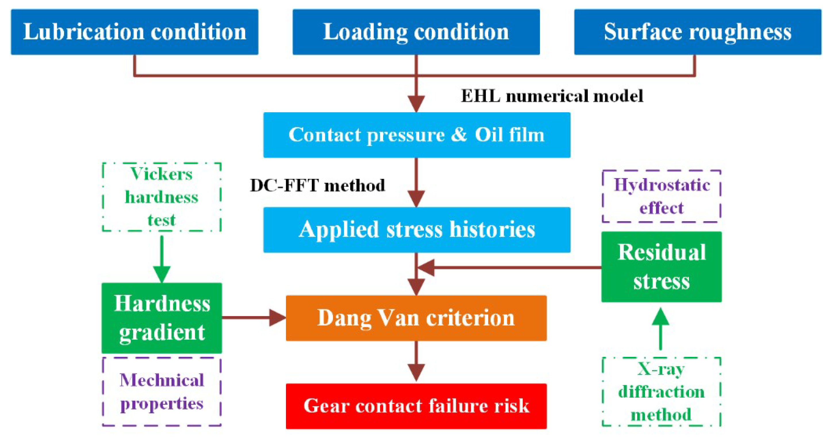
3. The Contact Fatigue Failure Competitive Mechanism Considering Wear Effect

When investigating the micropitting mechanism, the majority of the aforementioned works do not consider another important factor, namely the wear effect. During the cycling contact, the main loss of the material is caused by the wear process [2], changing the gear surface topography simultaneously. This may lead to the alternate occurrences among the several contact failure modes, which could be regarded as a failure competitive mechanism. Consequently, the effect of the wear process on the contact fatigue performances should also be taken into account in order to draw relatively accurate conclusions [46].

3.1. Review on the Studies Considering the Competitive Mechanism

The recent progress in the study of the competitive mechanism among contact fatigue failures and wear damage is mainly attributed to the works of the research teams of Morales-Espejel and Brandão.
In 2011, Morales-Espejel and Brizmer [122] established a model for the micropitting of rolling bearings under the sliding-rolling condition. In their work, a concept called competitive mechanism between the surface fatigue failures and mild wear was first raised. The effects of roughness, lubrication, sliding, etc. were considered and the wear process was simulated based on the Archard’s model [123]. Morales-Espejel et al. [46] explained that the existence of wear could move the micropits inside the single pair contact region, rather than to the extremes positions when the wear was not taken into account.
Brandão et al. [2] developed a numerical method to simulate the concurrent gear micropitting and mild wear. However, they just considered the Archard’s wear model and the surface fatigue models in succession only and summarized that combining the wear model and surface fatigue model was very important to develop a good micropitting model.
In addition, Vrcek et al. [107] assessed the micro-pitting and wear performances of engine oils under the boundary lubrication condition. Based on the test results, they claimed that micropitting and mild wear were competing phenomena and that higher micropitting damage would result in lower wear damage, which corresponds well with the previous research [108,124].
It is worth noting that some studies also mentioned the competitive mechanism between mild wear and the surface-initiated damage through indirect explanations, mainly stemming from investigations of micropitting phenomena with extreme pressure (EP) or anti-wear (AW) additives. For instance, Benyajati et al. [125] designed micropitting tests by applying a new miniature test-rig. They stated that certain anti-wear additives, like ZDDP, might be detrimental to micropitting resistance since they prevented wear (decline the smoothing rate of surface roughness) rather than by any direct influence on micropitting. As recorded in Reference [85], the mild wear would smoothen the surface roughness and reduce the micropitting risk simultaneously, suggesting that other failure modes like pitting might play a dominant role during meshing. However, when the anti-wear additive was applied, the initial surface roughness persisted, leading to severe micropitting. However, O’Connor [126] explained that EP or AW additives should not be simply defined as beneficial or detrimental on micropitting resistance since the chemical structure and the interaction effects of the additives could remarkably influence micropitting through a complicated way. Therefore, more detailed tribochemical studies of lubricants additives on the gear RCF and micropitting performance are needed.

3.2. Progress on Competitive Mechanism

In this regard, the authors also studied the gear contact failure competitive mechanism resulting from wear process [104]. Instead of revealing the competitive phenomenon between the contact failures and wear, the competitive mechanism between micropitting and pitting due to the wear effect was investigated. According to Figure 14, the wear depth accumulation could be primarily predicted on the LPSTC of the driven gear based on the initial surface roughness through the Archard’s wear model [123].
Based on the aforementioned gear pair sample and numerical model in Section 2, combined with the Morrow–Brown–Miller multiaxial criterion and the Palmgren–Miner rule [127], the competitive mechanism between micropitting and pitting considering the wear process could be primarily investigated through the damage accumulation distributions. The Palmgren–Miner rule can be expressed as follows:
D = i = 1 m D i = i = 1 m n i N i 1.0
where D is the total damage accumulation during the loading cycles, Di means the damage suffered during a loading block, ni denotes the actual number of cycles experienced under the current loading stage, Ni represents the fatigue life at the corresponding constant amplitude loading condition calculated by using the Morrow–Brown–Miller criterion. The total damage accumulation won’t exceed the threshold value of 1.0 before the final failure occurs [61].
However, it is quite time-consuming when estimating the damage accumulation of each loading cycle because of the high-cycle fatigue characteristics of the gears. Hence a method called “jump-in-cycles” reported in Reference [128] was applied for both the calculation accuracy and efficiency. Based on this method, the gear surface roughness could be assumed to remain unchanged over a finite loading block ΔN. In the authors’ work, the loading cycles number within a loading block was decided to be ΔN = 1 × 10⁶.
Figure 17 shows the surface roughness profile of different damage stages [104]. As the wear process proceeds, the volumetric and the smooth wear effects on the surface roughness would occur simultaneously. Therefore, in order to guarantee the relative accuracy of the surface roughness RMS evaluation, the reference lines of these worn surface roughness profiles at different damage stages along the rolling direction are adjusted to be the x-coordinate in order to meet the RMS calculation requirement. During the wear process, the surface roughness decreases from 0.25 μm (initial stage) to about 0.07 μm (when the maximum damage accumulation reaches 1.0).
Figure 18 displays the damage accumulation within every certain damage stage (ΔD = 0.2) [104]. The maximum damage accumulation appears at about 0.03 mm near the surface, where micropitting plays a dominant role compared with pitting failure. However, as the wear process proceeds, the depth of the maximum damage increases gradually. Consequently, the subsurface failure risk like pitting risk becomes predominant as can be seen when the total damage accumulation D reaches 1.0, the maximum damage accumulation occurs at a depth of about 0.28 mm. This indicates that the micropitting risk would gradually change to the pitting risk when the wear is considered.
Additionally, the effect of the initial surface roughness on the competitive mechanism has also been studied. Figure 19 displays the depth of the maximum damage accumulation (when D = 0.2) of different initial surface roughness values from 0.07 to 0.25 μm [104]. The depth of the maximum damage accumulation decreases from around 0.28 mm (initial roughness RMS = 0.07 μm) to around 0.027 mm (initial roughness RMS = 0.25 μm). The region around 0.1 mm could be set as the critical region to distinguish the occurrences of pitting and micropitting [9]. Hence, when the initial surface RMS is less than about 0.18 μm, the micropitting may completely disappear during the whole loading cycle, which agrees well with the results of the aforementioned studies.
Furthermore, the numerical results were also verified through the experimental results. Figure 20 displays the evolutions of both the measured roller surface roughness and the simulated octahedral shear stress from 1 to 40 million cycles [121]. The Hertzian center represents the contact center of the Hertzian contact width based on the Hertzian contact theory. During the first 20 million cycles, the wear effect on the surface roughness is significant. A similar trend of variation could also be observed on the octahedral shear stress distributions. The wear can obviously reduce the surface roughness asperities within the running-in stage, subsequently mitigating the micropitting damage to a certain extent. This would lead to a competitive phenomenon since the micropitting is suppressed by the wear. Meanwhile, other failure modes such as pitting or tooth flank fracture may become more dominant gradually.

4. Conclusions

In this work, plenty of relevant studies on the micropitting of steel gears, especially the competitive phenomena that occurs among several contact fatigue failure modes when considering gear tooth surface wear effect, are reviewed. Meanwhile, some recent research results about gear micropitting obtained by the authors are also illustrated for more comprehensive discussions. Several conclusions can be summarized as follows:
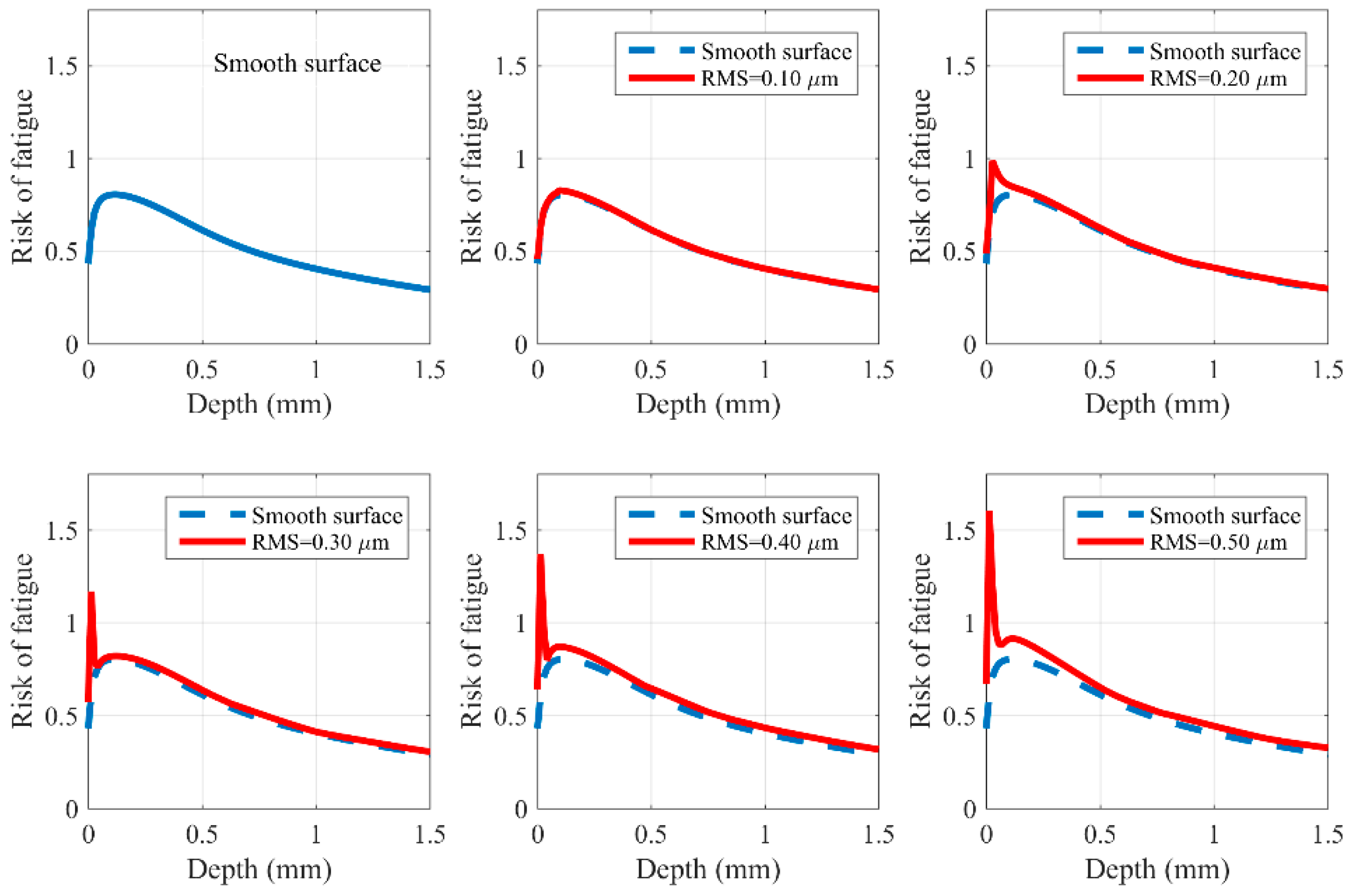
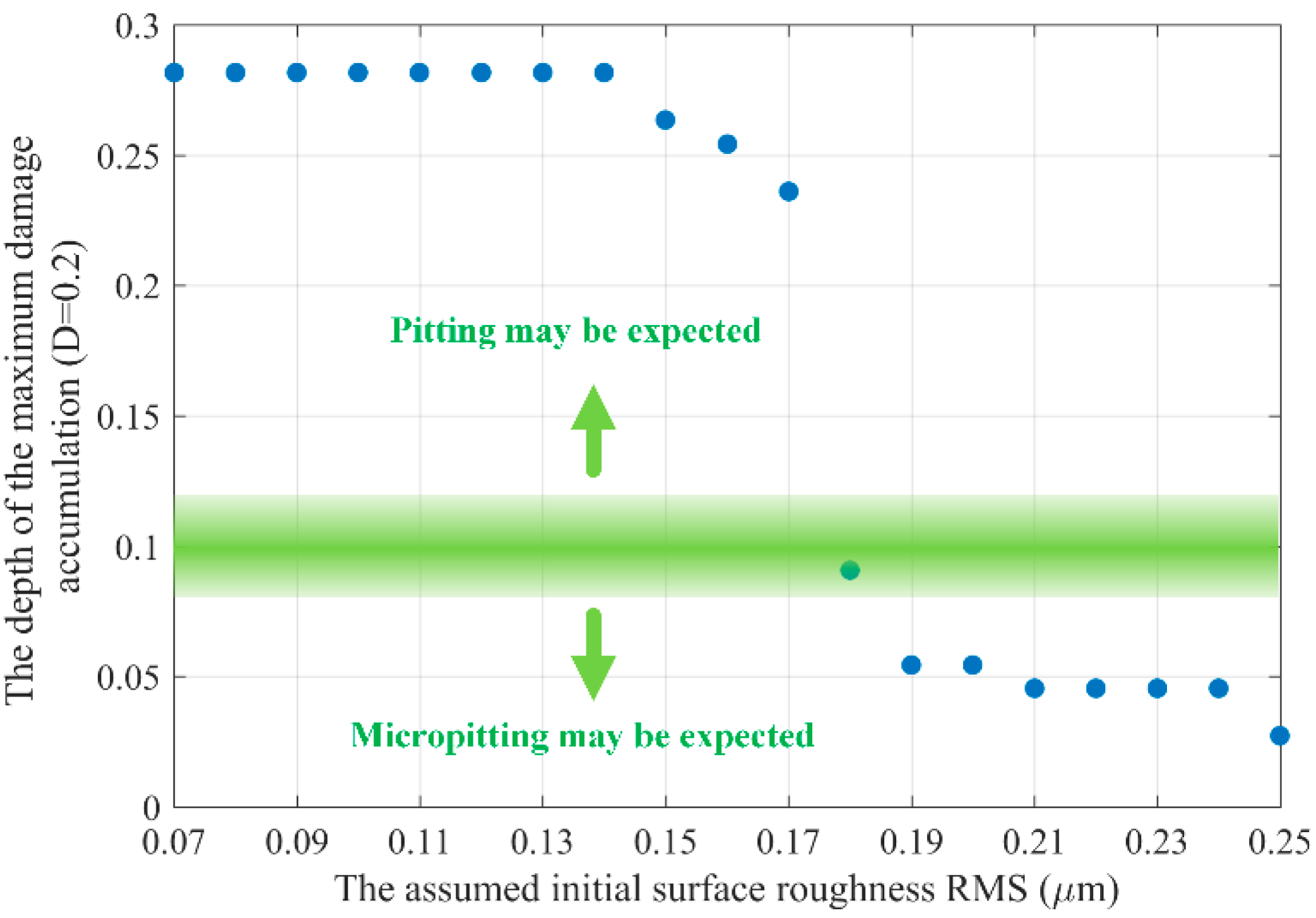
  • The gear micropitting resistance can be influenced by both macroscopic and microscopic geometry factors. The appropriate gear tooth modification method is beneficial to the anti-micropitting capacity. The increase of the surface roughness RMS makes the maximum index of failure risk significantly increase and its occurrence position comes closer to the surface (about 0.05 mm when RMS = 0.5 μm), where the micropitting is more likely to occur. However, the superfinishing may completely eliminate micropitting due to mitigating the effect of surface roughness.
  • The micropitting initiation is mostly controlled by contact pressure, whereas the propagation process can be significantly influenced by the sliding/rolling condition, and the micropitting damage may commonly be observed at higher speeds. With the increase of the specific lubricant film thickness from 0.06 to 0.17, the micropitting damage becomes more severe unless the Ra of the surface roughness is relatively low. The extreme pressure (EP) or anti-wear (AW) lubricant additives may be detrimental to the micropitting resistance because the surface roughness can be protected from wearing, leading to greater micropitting damage at the running-in stage.
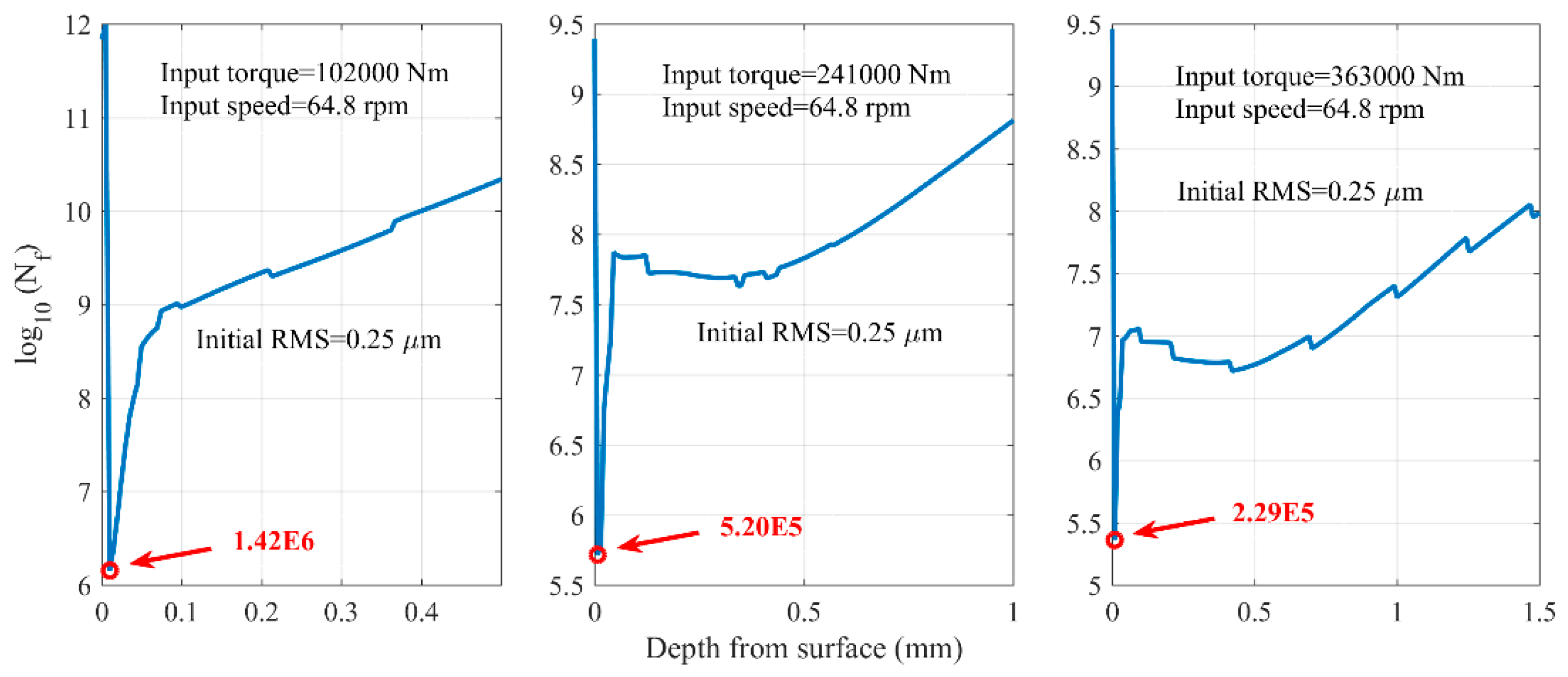
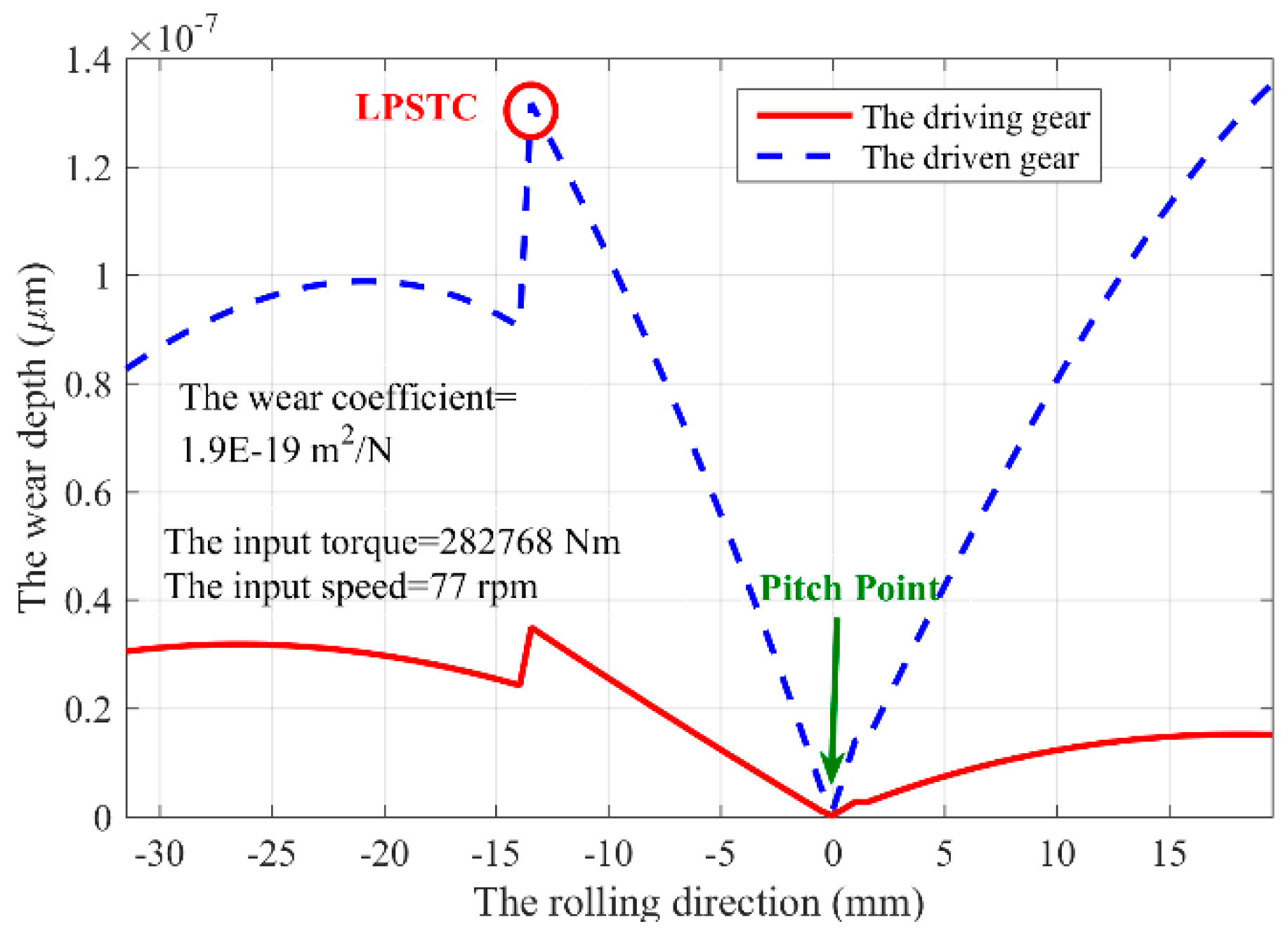
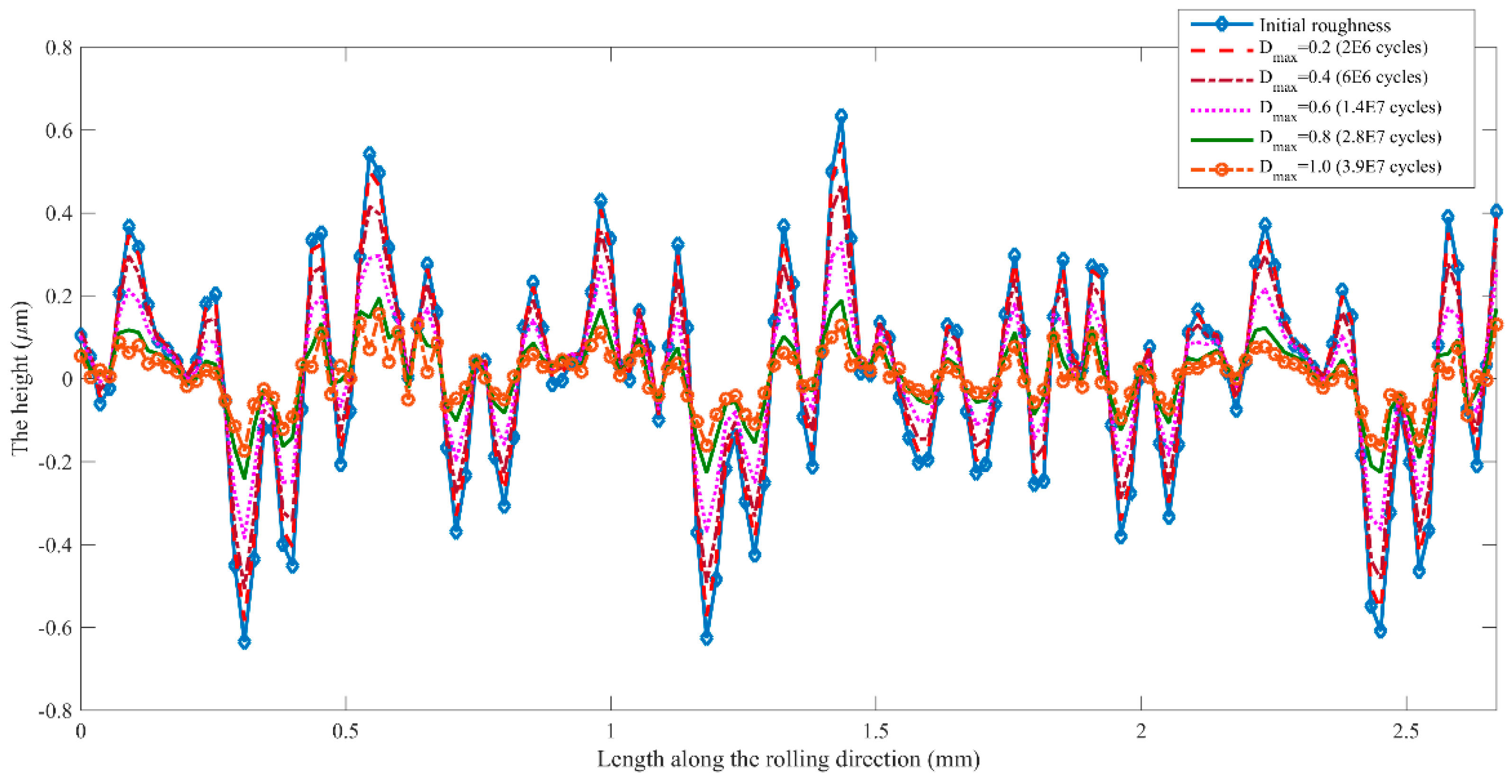
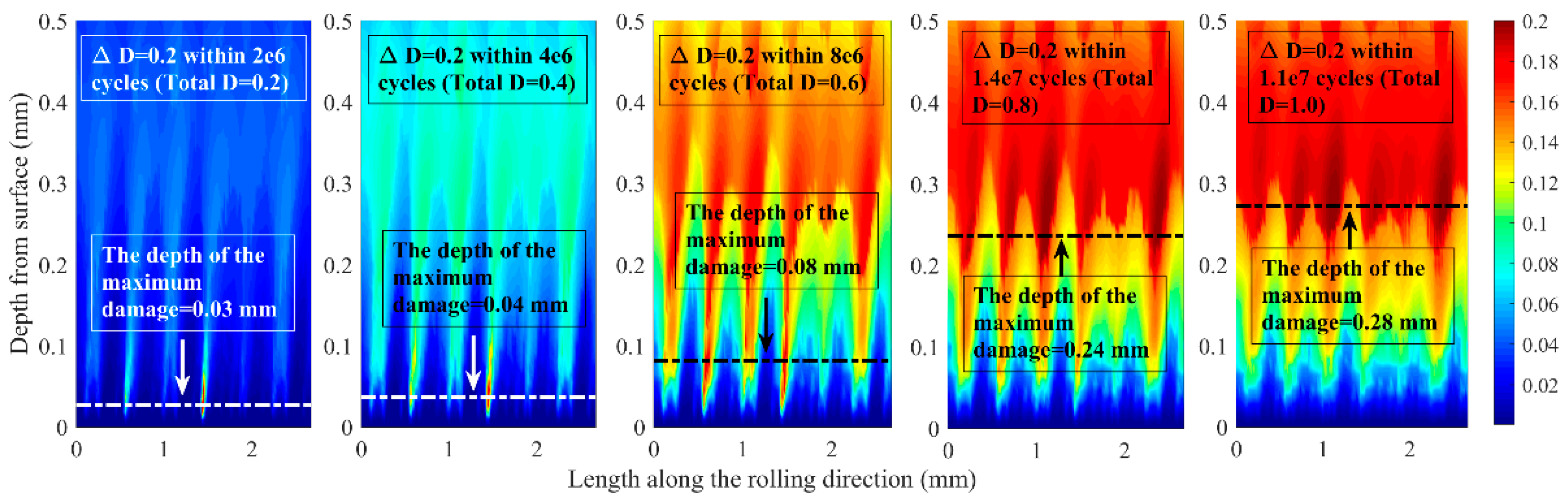
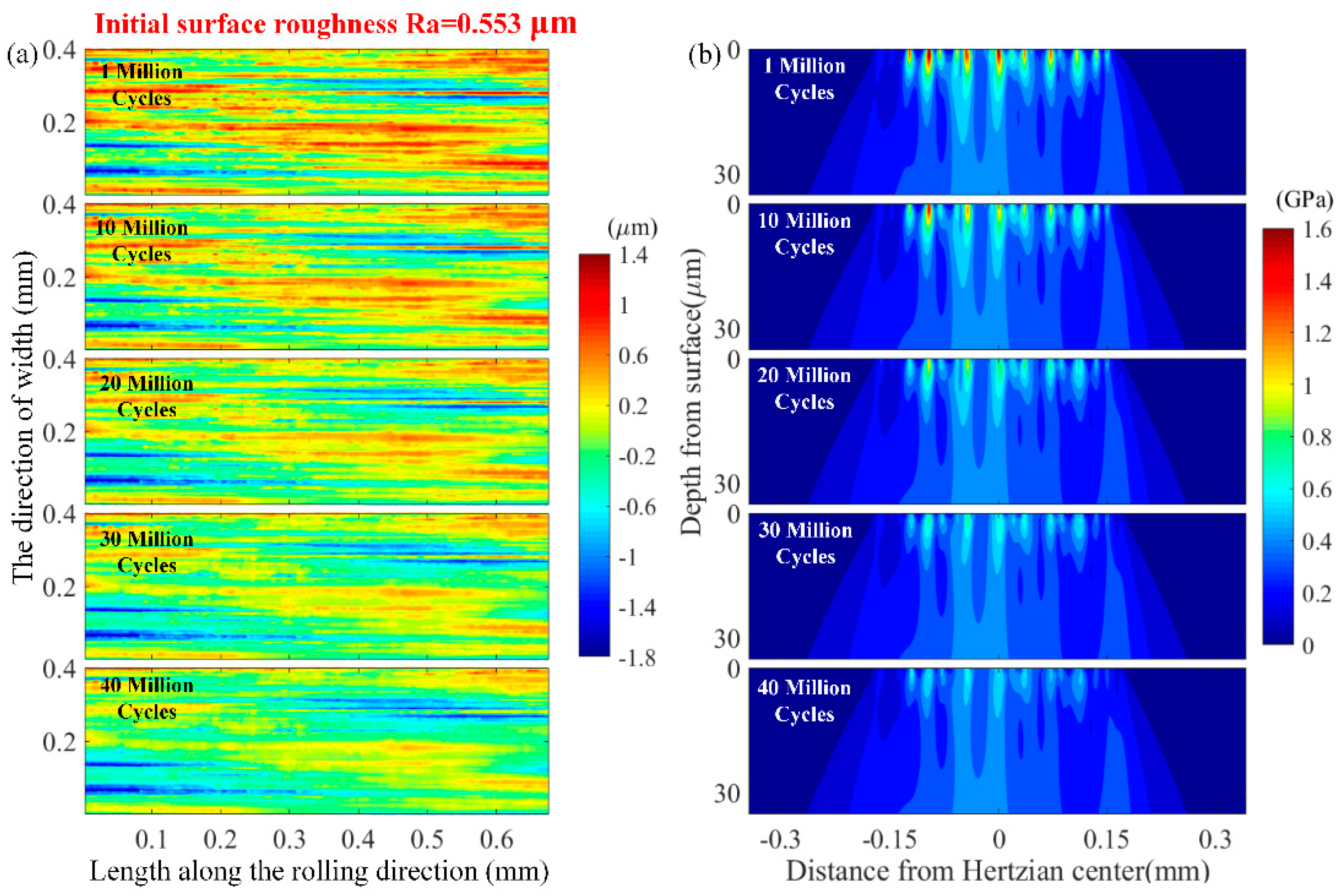
  • Merging the effects of the wear process and surface fatigue failure damages of the gear tooth surface is essential for the successful gear micropitting modelling. During the wear process, the position of the maximum damage accumulation moves gradually from near-surface to subsurface, indicating that the pitting failure is becoming more dominant than micropitting. The occurrence probability of micropitting can be significantly reduced due to the existence of the wear, resulting in the competitive mechanism between micropitting and pitting during the loading cycles.
Although impressive progress has been achieved on gear micropitting, and numerous factors have been considered in gear contact fatigue analysis [129,130,131], the micropitting mechanism still has not been fully revealed. The combined consideration of materials, structures, working condition, chemistry factors, etc., is much more necessary to numerical and experimental gear micropitting investigations for both the academic study and the industry.

Funding

This research was funded by National Natural Science Foundation of China (Nos. 51775060, 51805049, U1864210).

Conflicts of Interest

The authors declare no conflict of interest. The funders had no role in the design of the study; in the collection, analyses, or interpretation of data; in the writing of the manuscript, or in the decision to publish the results.

Nomenclutare

AWAnti-wear
b ,   c The fatigue strength index and the ductility index, respectively
C 1 ,   C 2 The constants used in Morrow–Brown–Miller criterion
B Contact tooth width, m
c The tip clearance coefficient
D The damage accumulation
E 1 ,   E 2 Young’s modulus of the driving and the driven gears, respectively, Pa
EHLElastohydrodynamic lubrication
EPExtreme pressure
h 0 The lubricant film thickness with the assumption that the contact surface is smooth, μm
h w The wear depth, m
k The wear coefficient, m2 N−1
LOALine of action
LPSTCThe lowest point of single tooth contact
m 0 The normal module of the gear pair, m
MPRMicropitting rig
MSIMicropitting severity index
N ref The reference input speed of the driving gear, rpm
N f The number of cycles of fatigue
p H The maximum Hertzian contact pressure, Pa
p m The mean value of the local contact pressure, Pa
RAThe retained austenite
RCFRolling contact fatigue
RMSThe root-mean-square, μm
R a The effective arithmetic mean roughness value, μm
R q 1 ,   R q 2 The RMS of contact surfaces of the driving and the driven gears, respectively, μm
R q The combined RMS value, μm
s The relative sliding distance, m
S λ The safety factor representing the micropitting load capacity
S λ ,   min The minimum required safety factor
SRRThe slide-roll ratio
T ref The reference input torque of the driving gear, Nm
x 1 ,   x 2 The shifting coefficients of the driving and the driven gears, respectively
Z 1 ,   Z 2 The teeth number of the driving and the driven gears, respectively
ZDDPThe Zinc Dialkyl Dithiophosphate
α 0 The pressure angle of the gear, °
α D The material parameter used in Dang Van criteria
α t The transverse pressure angle of the gear,°
β 0 The helix angle of the gear, °
σ f The axial fatigue strength coefficient, MPa
σ m The mean of the normal stress at the critical plane, MPa
Δ γ max / 2 The maximum amplitude of the shear strain
τ Dang Van The Dang Van equivalent stress, MPa
τ max The maximum shear stress, MPa
ε f The axial fatigue ductility coefficient
Δ ε n / 2 The amplitude of normal tensile strain at the critical plane
υ 1 ,   2 The Poisson’s ratio of materials
λ The specific lubricant film thickness
λ min The minimum specific lubricant film thickness in the contact area
λ p The permissible specific lubricant film thickness

References

  1. Oila, A.; Bull, J. Assessment of the factors influencing micropitting in rolling/sliding contacts. Wear 2005, 258, 1510–1524. [Google Scholar] [CrossRef]
  2. Brandão, J.; Martins, R.; Seabra, J.; Castro, M. An approach to the simulation of concurrent gear micropitting and mild wear. Wear 2015, 324–325, 64–73. [Google Scholar] [CrossRef]
  3. Terrin, A.; Dengo, C.; Meneghetti, G. Experimental analysis of contact fatigue damage in case hardened gears for off-highway axles. Eng. Fail. Anal. 2017, 76, 10–26. [Google Scholar] [CrossRef]
  4. Höhn, B.-R.; Oster, P.; Emmert, S. Micropitting in case-carburized gears-FZG micro-pitting test. VDI Berichte 1996, 1230, 331–344. [Google Scholar]
  5. Sheng, S. Wind Turbine Micropitting Workshop: A Recap; National Renewable Energy Laboratory: Golden, CO, USA, 2010.
  6. Winkelmann, L. Surface Roughness and Micropitting; National Renewable Energy Laboratory, Wind Turbine Tribology Seminar: Golden, CO, USA, 2011.
  7. Martins, R.; Locatelli, C.; Seabra, J. Evolution of tooth flank roughness during gear micropitting tests. Ind. Lubr. Tribol. 2011, 63, 34–45. [Google Scholar] [CrossRef]
  8. Brandão, J.; Seabra, J.; Castro, J. Surface initiated tooth flank damage: Part I: Numerical model. Wear 2010, 268, 1–12. [Google Scholar] [CrossRef]
  9. Brandão, J.; Seabra, J.; Castro, J. Surface initiated tooth flank damage. Part II: Prediction of micropitting initiation and mass loss. Wear 2010, 268, 13–22. [Google Scholar] [CrossRef]
  10. Whitby, R. Micropitting: An engineering or chemistry problem? Tribol. Lubr. Technol. 2004, 60, 56. [Google Scholar]
  11. Winter, H.; Oster, P. Influence of the Lubricant on Pitting and Micro Pitting (Grey Staining, Frosted Areas) Resistance of Case Carburized Gears: Test Procedures; American Gear Manufacturers Association: Alexandria, VI, USA, 1987. [Google Scholar]
  12. Brechot, P.; Cardis, A.; Murphy, W.; Theissen, J. Micropitting resistant industrial gear oils with balanced performance. Ind. Lubr. Tribol. 2000, 52, 125–136. [Google Scholar] [CrossRef]
  13. Sun, Y.; Bailey, R. Effect of sliding conditions on micropitting behaviour of AISI 304 stainless steel in chloride containing solution. Corros. Sci. 2018, 139, 197–205. [Google Scholar] [CrossRef]
  14. Way, S. Pitting due to rolling contact. J. Appl. Mech. 1935, 2, A49–A58. [Google Scholar]
  15. Dawson, P. Effect of metallic contact on the pitting of lubricated rolling surfaces. J. Mech. Eng. Sci. 1962, 4, 16–21. [Google Scholar] [CrossRef]
  16. Berthe, D.; Flamand, L.; Foucher, D.; Godet, M. Micropitting in Hertzian contacts. J. Lubr. Technol. 1980, 102, 478–489. [Google Scholar] [CrossRef]
  17. Snidle, R.; Evans, H. Elastohydrodynamics of gears. Tribol. Ser. 1997, 271–280. [Google Scholar] [CrossRef]
  18. Olver, A. Gear lubrication-a review. Proc. Inst. Mech. Eng. Part J J. Eng. Tribol. 2002, 216, 255–267. [Google Scholar] [CrossRef]
  19. Tallian, T. On competing failure modes in rolling contact. ASLE Trans. 1967, 10, 418–439. [Google Scholar] [CrossRef]
  20. ISO/TR 15144-1:2010 Calculation of Micropitting Load Capacity of Cylindrical Spur and Helical Gears-Part 1: Introduction and Basic Principles; ISO: Geneva, Switzerland, 2010.
  21. Höhn, B.-R.; Michaelis, K. Influence of oil temperature on gear failures. Tribol. Int. 2004, 37, 103–109. [Google Scholar] [CrossRef]
  22. Höhn, B.-R.; Oster, P.; Radev, T.; Steinberger, G.; Tobie, T. Improvement of standardized test methods for evaluating the lubricant influence on micropitting and pitting resistance of case carburized gears. In Proceedings of the AGMA Fall Technical Meeting, Orlando, FL, USA, 22–24 October 2006. [Google Scholar]
  23. Houser, D.; Shon, S. An Experimental Evaluation of the Procedures of the ISO/TR 15144 Technical Report for the Prediction of Micropitting. In Proceedings of the AGMA Fall Technical Meeting, Detroit, MI, USA, 2–4 October 2016. [Google Scholar]
  24. Long, H.; Al-Tubi, I.; Martineze, M. Analytical and Experimental Study of Gear Surface Micropitting due to Variable Loading. Appl. Mech. Mater. 2015, 750, 96–103. [Google Scholar] [CrossRef]
  25. Al-Tubi, I.; Long, H.; Zhang, J.; Shaw, B. Experimental and analytical study of gear micropitting initiation and propagation under varying loading conditions. Wear 2015, 328, 8–16. [Google Scholar] [CrossRef] [Green Version]
  26. ISO/TR 15144-1:2014 Calculation of Micropitting Load Capacity of Cylindrical Spur and Helical Gears-Introduction and Basic Principles; ISO: Geneva, Switzerland, 2014.
  27. Clarke, A.; Weeks, I.; Snidle, R.; Evans, H. Running-in and micropitting behaviour of steel surfaces under mixed lubrication conditions. Tribol. Int. 2016, 101, 59–68. [Google Scholar] [CrossRef] [Green Version]
  28. Jao, T.; Rollin, A.; Carter, R.; Aylott, C.; Shaw, B. Influence of Material Property on Micropitting and Pitting Behavior. In Proceedings of the World Tribology Congress III, Washington, DC, USA, 12–16 September 2005; Volume 2, pp. 103–104. [Google Scholar]
  29. Oila, A.; Bull, S. Phase transformations associated with micropitting in rolling/sliding contacts. J. Mater. Sci. 2005, 40, 4767–4774. [Google Scholar] [CrossRef]
  30. D’Errico, F. Micropitting Damage Mechanism on Hardened and Tempered, Nitrided, and Carburizing Steels. Mater. Manuf. Processes 2011, 26, 7–13. [Google Scholar] [CrossRef]
  31. Martins, R.; Seabra, J.; Magalhães, L. Micropitting of Austempered Ductile Iron Gears: Biodegradable Ester vs. Mineral Oil. Revista da Associação Portuguesa de Análise Experimental de Tensões 2006, 122, 922. [Google Scholar]
  32. Wilkinson, C.; Olver, A. The Durability of Gear and Disc Specimens-Part I: The Effect of Some Novel Materials and Surface Treatments. ASLE Trans. 1999, 42, 503–510. [Google Scholar] [CrossRef]
  33. Oila, A.; Shaw, B.; Aylott, C.; Bull, S. Martensite decay in micropitted gears. Proc. Inst. Mech. Eng. Part J J. Eng. Tribol. 2005, 219, 77–83. [Google Scholar] [CrossRef]
  34. Le, M.; Ville, F.; Kleber, X.; Cavoret, J.; Sainte-Catherine, M.; Briancon, L. Influence of grain boundary cementite induced by gas nitriding on the rolling contact fatigue of alloyed steels for gears. Proc. Inst. Mech. Eng. Part J J. Eng. Tribol. 2015, 229, 917–928. [Google Scholar] [CrossRef]
  35. Tobie, T.; Hippenstiel, F.; Mohrbacher, H. Optimizing gear performance by alloy modification of carburizing steels. Metals 2017, 7, 415. [Google Scholar] [CrossRef]
  36. Roy, S.; Ooi, G.; Sundararajan, S. Effect of retained austenite on micropitting behavior of carburized AISI 8620 steel under boundary lubrication. ACTA Mater. 2018, 3, 192–201. [Google Scholar] [CrossRef]
  37. Liu, S.; Song, C.; Zhu, C.; Ni, G. Effects of tooth modifications on mesh characteristics of crossed beveloid gear pair with small shaft angle. Mech. Mach. Theory 2018, 119, 142–160. [Google Scholar] [CrossRef]
  38. Kissling, U. Application of the first international calculation method for micropitting. Gear Technol. 2012, 29, 54–60. [Google Scholar]
  39. Predki, W.; Nazifi, K.; Lutzig, G. Micropitting of Big Gearboxes: Influence of Flank Modification and Surface Roughness. Gear Technol. 2011, 42–46. [Google Scholar]
  40. Li, S. An investigation on the influence of misalignment on micro-pitting of a spur gear pair. Tribol. Lett. 2015, 60, 35. [Google Scholar] [CrossRef]
  41. Weber, C.; Tobie, T.; Stahl, K. Investigation on the flank surface durability of gears with increased pressure angle. Forsch. Ingenieurwes 2017, 81, 207–213. [Google Scholar] [CrossRef]
  42. Ni, G.; Zhu, C.; Song, C.; Shi, J.; Liu, S. Effects of rack-cutter parabolic modification on loaded contact characteristics for crossed beveloid gears with misalignments. Int. J. Mech. Sci. 2018, 141, 359–371. [Google Scholar] [CrossRef]
  43. Liu, S.; Song, C.; Zhu, C.; Fan, Q. Concave modifications of tooth surfaces of beveloid gears with crossed axes. Proc. Inst. Mech. Eng. C J. Mech. 2018, 0954406218768842. [Google Scholar] [CrossRef]
  44. Clarke, A.; Evans, H.P.; Snidle, R. Understanding micropitting in gears. Proc. Inst. Mech. Eng. C J. Mech. 2016, 230, 1276–1289. [Google Scholar] [CrossRef]
  45. Bell, M.; Sroka, G.; Benson, R. The Effect of the Surface Roughness Profile on Micropitting. Gear Solutions, 8 March 2013; 46–53. [Google Scholar]
  46. Morales-Espejel, G.; Rycerz, P.; Kadiric, A. Prediction of micropitting damage in gear teeth contacts considering the concurrent effects of surface fatigue and mild wear. Wear 2018, 398, 99–115. [Google Scholar] [CrossRef]
  47. Evans, H.; Snidle, R.; Sharif, K.; Shaw, B.; Zhang, J. Analysis of micro-elastohydrodynamic lubrication and prediction of surface fatigue damage in micropitting tests on helical gears. J. Tribol. 2013, 135, 011501. [Google Scholar] [CrossRef]
  48. Sheng, L.; Ahmet, K. A physics-based model to predict micro-pitting lives of lubricated point contacts. Int. J. Fatigue 2013, 47, 205–215. [Google Scholar] [CrossRef]
  49. Li, S.; Kahraman, A. A micro-pitting model for spur gear contacts. Int. J. Fatigue 2014, 59, 224–233. [Google Scholar] [CrossRef]
  50. Li, S. A computational study on the influence of surface roughness lay directionality on micropitting of lubricated point contacts. J. Tribol. 2015, 137, 021401. [Google Scholar] [CrossRef]
  51. AL-Mayali, M.; Hutt, S.; Sharif, K.; Clarke, A.; Evans, H. Experimental and Numerical Study of Micropitting Initiation in Real Rough Surfaces in a Micro-elastohydrodynamic Lubrication Regime. Tribol. Lett. 2018, 66, 150. [Google Scholar] [CrossRef]
  52. Mallipeddi, D.; Norell, M.; Sosa, M.; Nyborg, L. The effect of manufacturing method and running-in load on the surface integrity of efficiency tested ground, honed and superfinished gears. Tribol. Int. 2019, 131, 277–287. [Google Scholar] [CrossRef]
  53. Liu, S.; Wang, Q.; Liu, G. A versatile method of discrete convolution and FFT (DC-FFT) for contact analyses. Wear 2000, 243, 101–111. [Google Scholar] [CrossRef]
  54. Zhang, Y.; Liu, H.; Zhu, C.; Liu, M.; Song, C. Oil film stiffness and damping in an elastohydrodynamic lubrication line contact-vibration. J. Mech. Sci. Technol. 2016, 30, 3031–3039. [Google Scholar] [CrossRef]
  55. Zhou, Y.; Zhu, C.; Liu, H.; Song, C.; Li, Z. A numerical study on the contact fatigue life of a coated gear pair under EHL. Ind. Lubr. Tribol. 2017, 70, 23–32. [Google Scholar] [CrossRef]
  56. Liu, H.; Zhu, C.; Sun, Z.; Song, C. Starved lubrication of a spur gear pair. Tribol. Int. 2016, 94, 52–60. [Google Scholar] [CrossRef]
  57. Charkaluk, E.; Constantinescu, A.; Maïtournam, H.; Van, D. Revisiting the Dang Van criterion. Procedia Eng. 2009, 1, 143–146. [Google Scholar] [CrossRef] [Green Version]
  58. Osman, T.; Velex, P. A model for the simulation of the interactions between dynamic tooth loads and contact fatigue in spur gears. Tribol. Int. 2012, 46, 84–96. [Google Scholar] [CrossRef]
  59. Liu, H.; Liu, H.; Zhu, C.; He, H.; Wei, P. Evaluation of Contact Fatigue Life of a Wind Turbine Gear Pair Considering Residual Stress. J. Tribol. 2018, 140, 041102. [Google Scholar] [CrossRef]
  60. Wang, W.; Liu, H.; Zhu, C.; Du, X.; Tang, J. Effect of the residual stress on contact fatigue of a wind turbine carburized gear with multiaxial fatigue criteria. Int. J. Mech. Sci. 2019, 151, 263–273. [Google Scholar] [CrossRef]
  61. Hua, Q. Prediction of Contact Fatigue for the Rough Surface Elastohydrodynamic Lubrication Line Contact Problem under Rolling and Sliding Conditions. Ph.D. Thesis, Cardiff University, Wales, UK, 2005. [Google Scholar]
  62. Ciavarella, M.; Maitournam, H. On the Ekberg, Kabo and Andersson calculation of the Dang Van high cycle fatigue limit for rolling contact fatigue. Fatigue Fract. Eng. Mech. 2004, 27, 523–526. [Google Scholar] [CrossRef] [Green Version]
  63. Liu, H.; Liu, H.; Zhu, C.; Sun, Z.; Wei, P. Study on contact fatigue of a wind turbine gear pair using the EHL model considering surface roughness. Friction, (accepted).
  64. Karpuschewski, B.; Knoche, H.; Hipke, M. Gear finishing by abrasive processes. CIRP Ann. Manuf. Technol. 2008, 57, 621–640. [Google Scholar] [CrossRef]
  65. Krantz, T.; Alanou, M.; Evans, H.; Snidle, R. Surface fatigue lives of case-carburized gears with an improved surface finish. J. Tribol. 2001, 123, 709–716. [Google Scholar] [CrossRef]
  66. Winkelmann, L.; El-Saeed, O.; Bell, M. The effect of superfinishing on gear micropitting. Gear Technol. 2009, 2, 60–65. [Google Scholar]
  67. Rabaso, P.; Gauthier, T.; Diaby, M.; Ville, F. Rolling Contact Fatigue: Experimental Study of the Influence of Sliding, Load, and Material Properties on the Resistance to Micropitting of Steel Discs. Tribol. Trans. 2013, 56, 203–214. [Google Scholar] [CrossRef]
  68. Shaikh, J.; Jain, N.; Venkatesh, V. Precision Finishing of Bevel Gears by Electrochemical Honing. Mater. Manuf. Processes 2013, 28, 1117–1123. [Google Scholar] [CrossRef]
  69. Ronkainen, H.; Elomaa, O.; Varjus, S.; Kilpi, L.; Jaatinen, T.; Koskinen, J. The influence of carbon based coatings and surface finish on the tribological performance in High-load contacts. Tribol. Int. 2016, 96, 402–409. [Google Scholar] [CrossRef]
  70. Pariente, I.F.; Guagliano, M. Influence of shot peening process on contact fatigue behavior of gears. Mater. Manuf. Processes 2009, 24, 1436–1441. [Google Scholar] [CrossRef]
  71. Moorthy, V.; Shaw, B. Effect of as-ground surface and the BALINIT® C and Nb–S coatings on contact fatigue damage in gears. Tribol. Int. 2012, 51, 61–70. [Google Scholar] [CrossRef]
  72. Widmark, M.; Melander, A. Effect of material, heat treatment, grinding and shot peening on contact fatigue life of carburised steels. Int. J. Fatigue 1999, 21, 309–327. [Google Scholar] [CrossRef]
  73. Terrin, A.; Meneghetti, G. A comparison of rolling contact fatigue behaviour of 17NiCrMo6-4 case-hardened disc specimens and gears. Fatigue Fract. Eng. Mach. 2018, 41, 2321–2337. [Google Scholar] [CrossRef]
  74. Pariente, I.; Guagliano, M. Contact fatigue damage analysis of shot peened gears by means of X-ray measurements. Eng. Fail. Anal. 2009, 16, 964–971. [Google Scholar] [CrossRef]
  75. Koenig, J.; Koller, P.; Tobie, T.; Stahl, K. Correlation of relevant case properties and the flank load carrying capacity of case-hardened gears. In Proceedings of the ASME 2015 International Design Engineering Technical Conferences and Computers and Information in Engineering Conference, Boston, MA, USA, 2–5 August 2015. [Google Scholar]
  76. Qin, H.; Ren, Z.; Zhao, J.; Ye, C.; Doll, G.; Dong, Y. Effects of ultrasonic nanocrystal surface modification on the wear and micropitting behavior of bearing steel in boundary lubricated steel-steel contacts. Wear 2017, 392, 29–38. [Google Scholar] [CrossRef]
  77. Krantz, T.; Cooper, C.; Townsend, D.; Hansen, B. Increased surface fatigue lives of spur gears by application of a coating. J. Mech. Des. 2004, 126, 1047–1054. [Google Scholar] [CrossRef]
  78. Vetter, J.; Barbezat, G.; Crummenauer, J.; Avissar, J. Surface treatment selections for automotive applications. Surf. Coat. Technol. 2005, 200, 1962–1968. [Google Scholar] [CrossRef]
  79. Martins, R.; Amaro, R.; Seabra, J. Influence of low friction coatings on the scuffing load capacity and efficiency of gears. Tribol. Int. 2008, 41, 234–243. [Google Scholar] [CrossRef]
  80. Bayón, R.; Zubizarreta, C.; Nevshupa, R.; Carlos Rodriguez, J.; Fernández, X.; Ruiz de Gopegui, U.; Igartua, A. Rolling-sliding, scuffing and tribocorrosion behaviour of PVD multilayer coatings for gears application. Ind. Lubr. Tribol. 2011, 63, 17–26. [Google Scholar] [CrossRef]
  81. Moorthy, V.; Shaw, B. Contact fatigue performance of helical gears with surface coatings. Wear 2012, 276–277, 130–140. [Google Scholar] [CrossRef]
  82. Moorthy, V.; Shaw, B. An observation on the initiation of micro-pitting damage in as-ground and coated gears during contact fatigue. Wear 2013, 297, 878–884. [Google Scholar] [CrossRef]
  83. Singh, H.; Ramirez, G.; Eryilmaz, O.; Greco, A.; Doll, G.; Erdemir, A. Fatigue resistant carbon coatings for rolling/sliding contacts. Tribol. Int. 2016, 98, 172–178. [Google Scholar] [CrossRef] [Green Version]
  84. Benedetti, M.; Fontanari, V.; Torresani, E.; Girardi, C.; Giordanino, L. Investigation of lubricated rolling sliding behaviour of WC/C, WC/C-CrN, DLC based coatings and plasma nitriding of steel for possible use in worm gearing. Wear 2017, 378, 106–113. [Google Scholar] [CrossRef]
  85. Olver, A. The mechanism of rolling contact fatigue: An update. Proc. Inst. Mech. Eng. J J. Eng. Tribol. 2005, 219, 313–330. [Google Scholar] [CrossRef]
  86. Fajdiga, G.; Flašker, J.; Glodež, S.; Hellen, T. Numerical modelling of micro-pitting of gear teeth flanks. Fatigue Fract. Eng. Mach. 2003, 26, 1135–1143. [Google Scholar] [CrossRef]
  87. Webster, M.; Norbart, C. An Experimental Investigation of Micropitting Using a Roller Disk Machine. ASLE Trans. 1995, 38, 883–893. [Google Scholar] [CrossRef]
  88. Moallem, H.; Akbarzadeh, S.; Ariaei, A. Prediction of micropitting life in spur gears operating under mixed-lubrication regime using load-sharing concept. Proc. Inst. Mech. Eng. J J. Eng. Tribol. 2016, 230, 591–599. [Google Scholar] [CrossRef]
  89. Mallipeddi, D.; Norell, M.; Sosa, M.; Nyborg, L. Influence of running-in on surface characteristics of efficiency tested ground gears. Tribol. Int. 2017, 115, 45–58. [Google Scholar] [CrossRef] [Green Version]
  90. An, S.; Lee, S.; Son, J.; Cho, Y. New Approach for Prediction of Non-Conformal Contact Fatigue Life Considering Lubrication Performance Parameters. J. Frict. Wear 2017, 38, 419–423. [Google Scholar] [CrossRef]
  91. Brown, M.; Miller, K. A theory for fatigue failure under multiaxial stress-strain conditions. Proc. Inst. Mech. Eng. 1973, 187, 745–755. [Google Scholar] [CrossRef]
  92. Kadiric, A.; Rycerz, P. Influence of Contact Conditions on the Onset of Micropitting in Rolling-Sliding Contacts Pertinent to Gear Applications. Gear Solutions, 17 February 2017; 45–53. [Google Scholar]
  93. Martins, R.; Seabra, J.; Magalhães, L. Austempered ductile iron (ADI) gears: Power loss, pitting and micropitting. Wear 2008, 264, 838–849. [Google Scholar] [CrossRef]
  94. Morales-Espejel, G.; Gabelli, A. The Progression of Surface Rolling Contact Fatigue Damage of Rolling Bearings with Artificial Dents. Tribol. Trans. 2015, 58, 418–431. [Google Scholar] [CrossRef]
  95. Zhou, R.; Cheng, H.; Mura, T. Micropitting in rolling and sliding contact under mixed lubrication. J. Tribol. 1989, 111, 605–613. [Google Scholar] [CrossRef]
  96. Errichello, R. Morphology of micropitting. Gear Technol. 2012, 4, 74–81. [Google Scholar]
  97. Sanekata, J.; Koga, N.; Umezawa, O. Effects of Slip Ratio on Damage and Microcracks in Carburized SCM420 Steel under Rolling Contact Fatigue. Key Eng. Mater. 2017, 741, 94–98. [Google Scholar] [CrossRef]
  98. Cen, H.; Morina, A.; Neville, A. Effect of slide to roll ratio on the micropitting behaviour in rolling-sliding contacts lubricated with ZDDP-containing lubricants. Tribol. Int. 2018, 122, 210–217. [Google Scholar] [CrossRef]
  99. Flodin, A.; Andersson, S. A simplified model for wear prediction in helical gears. Wear 2001, 249, 285–292. [Google Scholar] [CrossRef]
  100. Krantz, T.; Kahraman, A. An experimental investigation of the influence of the lubricant viscosity and additives on gear wear. Tribol. Trans. 2005, 21, 138–148. [Google Scholar] [CrossRef]
  101. Brandão, J.; Martins, R.; Seabra, J.; Castro, M. Calculation of gear tooth flank surface wear during an FZG micropitting test. Wear 2014, 311, 31–39. [Google Scholar] [CrossRef]
  102. Al-Mayali, M.; Evans, H.; Sharif, K. Assessment of the effects of residual stresses on fatigue life of real rough surfaces in lubricated contact. In Proceedings of the International Conference for Students on Applied Engineering, Newcastle, UK, 20–21 October 2016; pp. 123–128. [Google Scholar]
  103. Janakiraman, V. An Investigation of the Impact of Contact Parameters on the Wear Coefficient. Ph.D. Thesis, The Ohio State University, Columbus, OH, USA, 2013. [Google Scholar]
  104. Liu, H.; Liu, H.; Zhu, C.; Tang, J. Study on contact fatigue failure competitive mechanism of a wind turbine gear pair considering tooth wear evolution. J. Tribol. (under review).
  105. Winter, H.; Oster, P. Influence of lubrication on pitting and micropitting resistance of gears. Gear Technol. 1990, 7, 16–23. [Google Scholar]
  106. Morales-Espejel, G.; Brizmer, V.; Piras, E. Roughness evolution in mixed lubrication condition due to mild wear. Proc. Inst. Mech. Eng. J J. Eng. Tribol. 2015, 229, 1330–1346. [Google Scholar] [CrossRef]
  107. Vrcek, A.; Hultqvist, T.; Baubet, Y.; Björling, M.; Marklund, P.; Larsson, R. Micro-pitting and wear assessment of engine oils operating under boundary lubrication conditions. Tribol. Int. 2019, 129, 338–346. [Google Scholar] [CrossRef]
  108. Lainé, E.; Olver, A.; Beveridge, T. Effect of lubricants on micropitting and wear. Tribol. Int. 2008, 41, 1049–1055. [Google Scholar] [CrossRef]
  109. Van-Rensselar, J. Trends in industrial gear oils. Tribol. Lubr. Technol. 2013, 69, 26–33. [Google Scholar]
  110. Errichello, R. Selecting and applying lubricants to avoid micropitting of gear teeth. Mach. Lubr. 2002, 2, 30–36. [Google Scholar]
  111. Martins, R.; Seabra, J. Micropitting performance of mineral and biodegradable ester gear oils. Ind. Lubr. Tribol. 2008, 60, 286–292. [Google Scholar] [CrossRef]
  112. Cardoso, R.; Martins, C.; Seabra, O.; Igartua, A.; Rodríguez, C.; Luther, R. Micropitting performance of nitrided steel gears lubricated with mineral and ester oils. Tribol. Int. 2009, 42, 77–87. [Google Scholar] [CrossRef]
  113. Lainé, E.; Olver, A.; Lekstrom, M.; Shollock, B.; Beveridge, T.; Hua, D. The Effect of a Friction Modifier Additive on Micropitting. Tribol. Trans. 2009, 52, 526–533. [Google Scholar] [CrossRef]
  114. De la Guerra Ochoa, E.; Otero, J.E.; Tanarro, E.C.; Munoz-Guijosa, J.; del Rio Lopez, B.; Cordero, C.A. Analysis of the effect of different types of additives added to a low viscosity polyalphaolefin base on micropitting. Wear 2015, 322, 238–250. [Google Scholar] [CrossRef]
  115. Soltanahmadi, S.; Morina, A.; van Eijk, M.C.; Nedelcu, I.; Neville, A. Investigation of the effect of a diamine-based friction modifier on micropitting and the properties of tribofilms in rolling-sliding contacts. J. Phys. D Appl. Phys. 2016, 49, 505302. [Google Scholar] [CrossRef] [Green Version]
  116. Engelhardt, C.; Witzig, J.; Tobie, T.; Stahl, K. Influence of water contamination in gear lubricants on wear and micro-pitting performance of case carburized gears. Ind. Lubr. Tribol. 2017, 69, 612–619. [Google Scholar] [CrossRef]
  117. Ward, W.; O’connor, B.; Vinci, J. Lubricants That Decrease Micropitting for Industrial Gears. U.S. Patent Application 11/866,696, 9 April 2009. [Google Scholar]
  118. Fu, X.; Hua, X.; Zhang, J. Industrial Gear Lubricating Oil Composition Used for Resisting Micro-Pitting. U.S. Patent 9,347,016, 24 May 2016. [Google Scholar]
  119. Moss, J.; Kahraman, A.; Wink, C. An Experimental Study of Influence of Lubrication Methods on Efficiency and Contact Fatigue Life of Spur Gears. J. Tribol. 2018, 140, 051103. [Google Scholar] [CrossRef]
  120. Seireg, A. Thermal stress effects on the surface durability of gear teeth. Proc. Inst. Mech. Eng. C J. Mech. 2001, 215, 973–979. [Google Scholar] [CrossRef]
  121. Zhou, Y.; Zhu, C.; Gould, B.; Demas, N.; Liu, H.; Greco, A. The effect of contact severity on micropitting: simulation and experiments. Tribol. Int. (under review).
  122. Morales-Espejel, G.; Brizmer, V. Micropitting Modelling in Rolling–Sliding Contacts: Application to Rolling Bearings. Tribol. Trans. 2011, 54, 625–643. [Google Scholar] [CrossRef]
  123. Archard, F. Contact and rubbing of flat surfaces. J. Appl. Phys. 1953, 24, 981–988. [Google Scholar] [CrossRef]
  124. Brizmer, V.; Pasaribu, H.; Morales-Espejel, G. Micropitting Performance of Oil Additives in Lubricated Rolling Contacts. Tribol. Trans. 2013, 56, 739–748. [Google Scholar] [CrossRef]
  125. Benyajati, C.; Olver, A.; Hamer, C. An experimental study of micropitting using a new miniature test-rig. Tribol. Ser. 2003, 43, 601–610. [Google Scholar]
  126. O’connor, B. The influence of additive chemistry on micropitting. Gear Technol. 2005, 22, 34–41. [Google Scholar]
  127. Yang, Q. Fatigue test and reliability design of gears. Int. J. Fatigue 1996, 18, 171–177. [Google Scholar] [CrossRef]
  128. Li, F.; Hu, W.; Meng, Q.; Zhan, Z.; Shen, F. A new damage-mechanics-based model for rolling contact fatigue analysis of cylindrical roller bearing. Tribol. Int. 2017, 120, 105–114. [Google Scholar] [CrossRef]
  129. Weibring, M.; Gondecki, L.; Tenberge, P. Simulation of fatigue failure on tooth flanks in consideration of pitting initiation and growth. Tribol. Int. 2019, 131, 299–307. [Google Scholar] [CrossRef]
  130. Wang, W.; Liu, H.; Zhu, C.; Wei, P.; Tang, J. Effects of microstructure on rolling contact fatigue of a wind turbine gear based on crystal plasticity modeling. Int. J. Fatigue 2019, 120, 73–86. [Google Scholar] [CrossRef]
  131. Rajinikanth, V.; Soni, M.K.; Mahato, B.; Rao, M.A. Study of microstructural degradation of a failed pinion gear at a cement plant. Eng. Fail. Anal. 2019, 95, 117–126. [Google Scholar] [CrossRef]
Figure 1. The failures observed in wind turbine gears related to micropitting.
Coatings 09 00042 g001
Figure 2. The reproduced micropits observed on the case-hardening and ground gear tooth flank after the experiments.
Coatings 09 00042 g002
Figure 3. (a) The schematic diagram of a beveloid tooth with a transverse profile slope modification and (b) profile crowning modification (Reprinted with permission from [37]. Copyright 2018 Elsevier).
Coatings 09 00042 g003
Figure 4. The minimum film thickness with different modification quantities of Case 4 (Reprinted with permission from [43]. Copyright 2018 SAGE).
Coatings 09 00042 g004
Figure 5. (a) The contact pattern of TCA with and without modification of Case 4; (b) The contact pattern of LTCA with and without modification of Case 4 (Reprinted with permission from [43]. Copyright 2018 SAGE).
Coatings 09 00042 g005
Figure 6. The technical route of contact failure risk evaluation with EHL considering different surface roughness states.
Coatings 09 00042 g006
Figure 7. The optical profiler and the initial surface roughness profile.
Coatings 09 00042 g007
Figure 8. The fitted (a) hardness and (b) residual stress profiles based on the experimental method.
Coatings 09 00042 g008
Figure 9. The index of contact fatigue failure risk along the depth with different RMS values [63].
Coatings 09 00042 g009
Figure 10. The schematic diagram of the calculation domain and the critical plane of RCF.
Coatings 09 00042 g010
Figure 11. The contact fatigue lives under different input loadings of the first loading cycle with initial surface roughness.
Coatings 09 00042 g011
Figure 12. The correlation between the micropitting crack propagation direction and the gear sliding/rolling condition (Reprinted with permission from [85,93]. Copyright 2005 SAGE & 2012 Gear Technology).
Coatings 09 00042 g012
Figure 13. The maximum Hertzian contact pressure and the SRR along the LOA [104].
Coatings 09 00042 g013
Figure 14. The wear depths of the driving and the driven gear along the LOA [104].
Coatings 09 00042 g014
Figure 15. The PCS Instruments triple-contact micropitting rig and the test roller [121].
Coatings 09 00042 g015
Figure 16. The roller surface and operating parameters of tests 1–4 (ad) [121].
Coatings 09 00042 g016
Figure 17. The surface roughness profile of different damage stage with the adjustment of the reference lines of the driven gear [104].
Coatings 09 00042 g017
Figure 18. The damage accumulation within every individual certain damage stage (∆D = 0.2) [104].
Coatings 09 00042 g018
Figure 19. The depth of the maximum damage accumulation (when D = 0.2) of different initial surface roughness values [104].
Coatings 09 00042 g019
Figure 20. (a) The evolution of surface roughness and (b) the evolution of octahedral shear stress from 1 million to 40 million cycles [121].
Coatings 09 00042 g020
Table 1. The gear parameters from the authors’ studies.
ParametersValuesParametersValues
Teeth NumberZ1 =121, Z2 = 24 Pressure Angleα0 = 20°
Normal Modulem0 = 0.011 mHelix Angleβ0 = 12°
Shifting Coefficientsx1 = 0.034, x2 = 0.4 Contact Tooth WidthB = 0.295 m
Poisson’s Ratio of Materialsv1,2 = 0.3 Young’s ModulusE1,2 = 2.10 × 10¹¹ Pa
Transverse Pressure Angleαt = 20.41°Tip Clearance Coefficientc* = 0.4
Reference Input Torque of the Gear PairTref = 241000 N mReference Input Speed of the Gear PairNref = 64.8 rpm

