Capturing the Competing Influence of Thermal and Mechanical Loads on the Strain of Turbine Blade Coatings via High Energy X-rays

 and
and 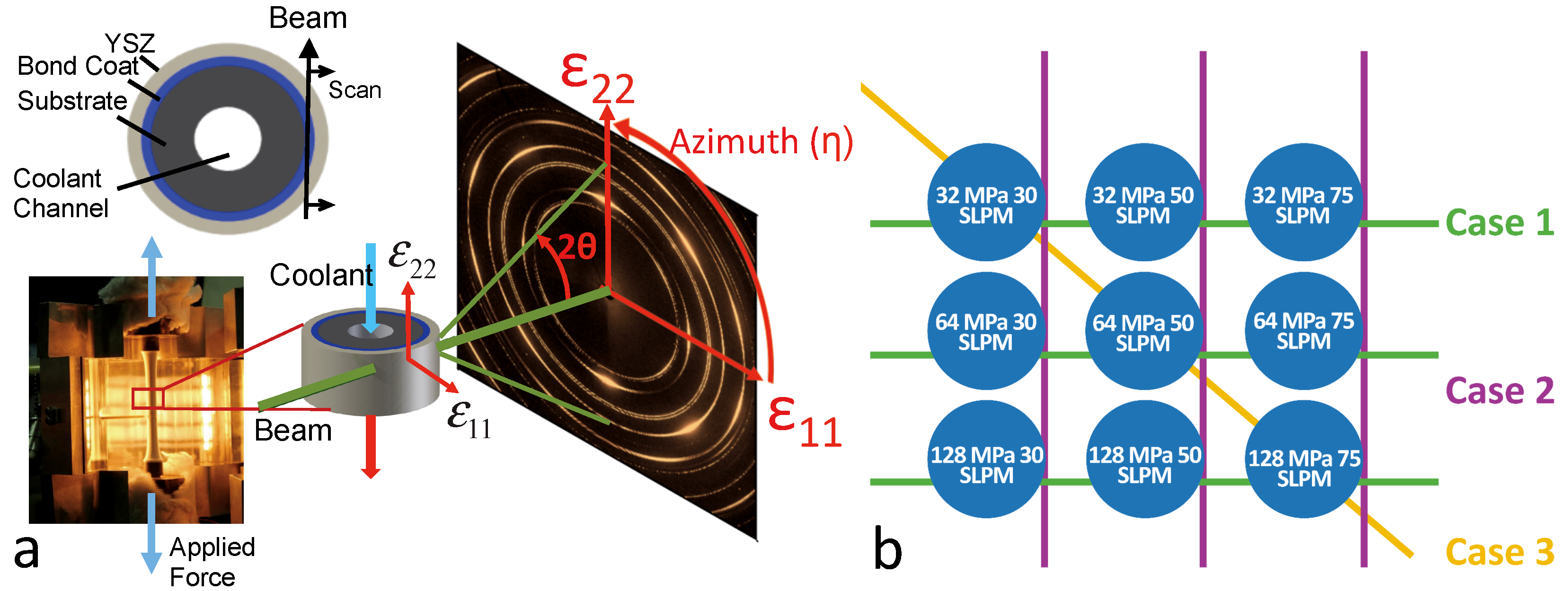
Abstract
:1. Introduction
2. Experimental
- Case 1: constant mechanical loading with variable internal cooling
- Case 2: constant internal cooling with variable mechanical loading
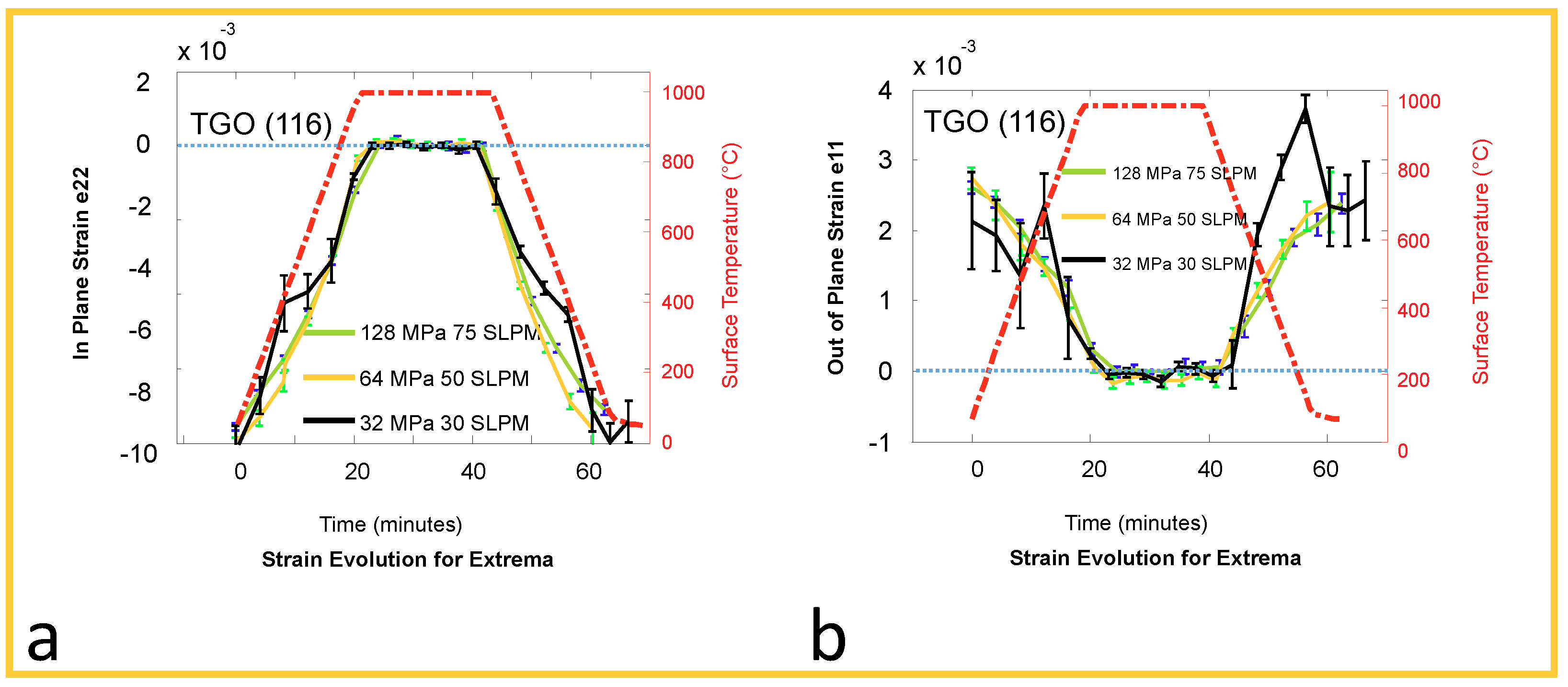
- Case 3: extrema of variable loading as follows:
- -
- Low mechanical loading/low flow
- -
- Mid-range mechanical loading/mid-range flow
- -
- High mechanical loading/high flow
2.1. Sample Manufacturing
2.2. Synchrotron Diffraction Measurements under Loading
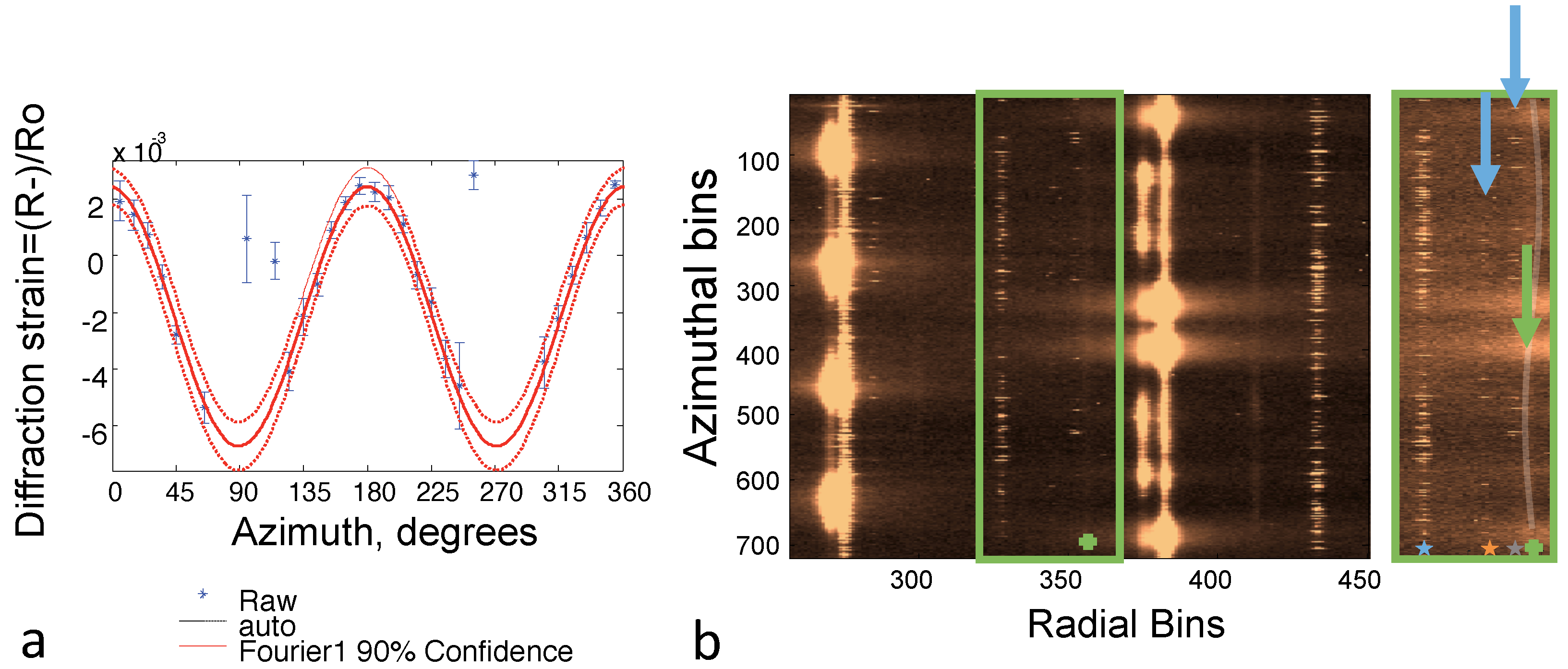
2.3. Statistical Analysis
3. Results and Discussion
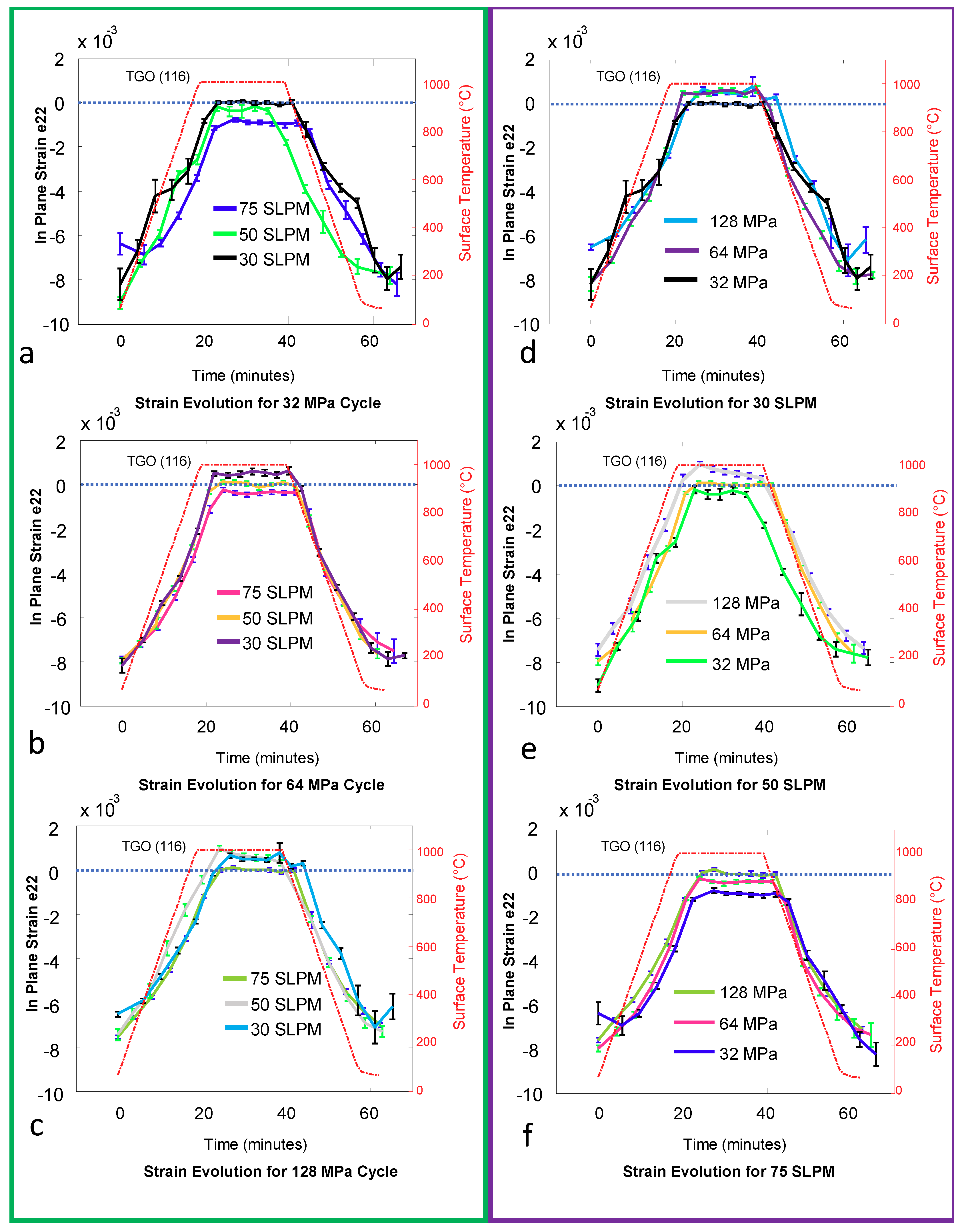
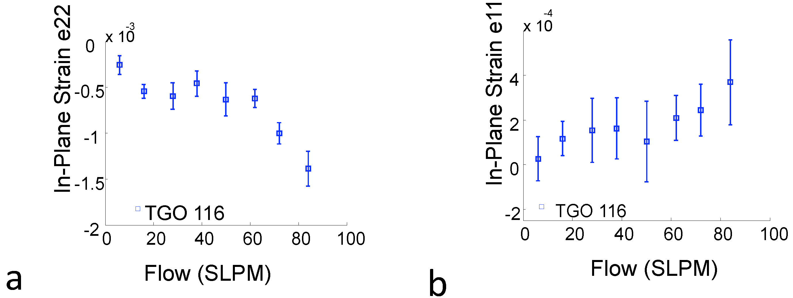
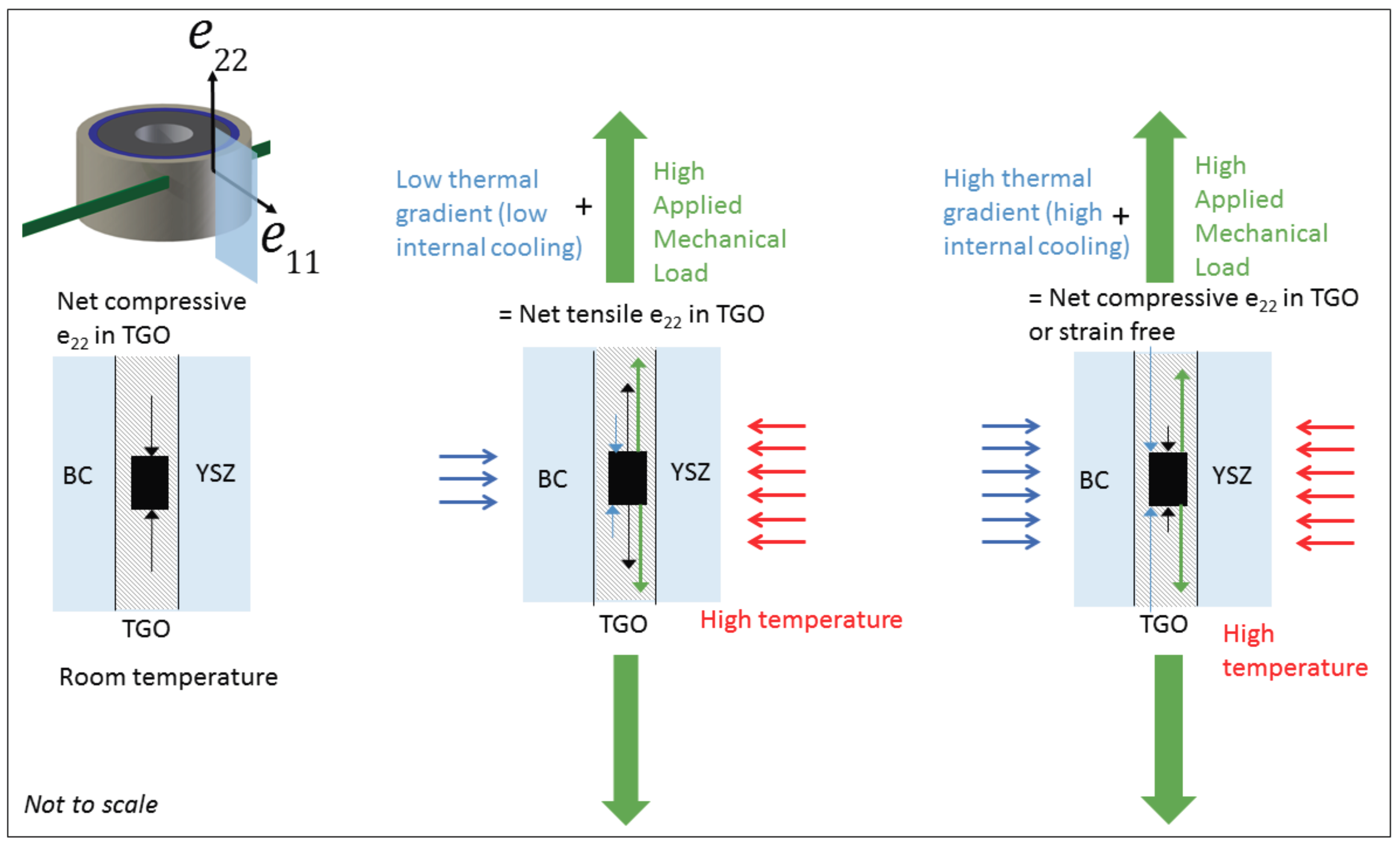
- Increasing internal cooling flow, at high temperature holds and constant mechanical load, results in decreasing strain, e22. That is, for the cases of lower mechanical constant load, the strain becomes more compressive, while for higher constant mechanical load, the strain goes from tensile to compressive. This is clearly seen in Figure 2a–c. This is mainly because the internal air cooling increases the thermal gradient across the specimens wall, resulting in constraining the expansion of the specimen, and a compressive TGO strain. Further, although the role of increased internal flow from low to high flow is distinct, the midrange flow measurement (50 SLPM) shows decreased confidence and sensitivity as elaborated in Section 2.3.
- Increasing mechanical loading, at constant flow and constant external temperature, will push the oxide scale into tension. This is of specific interest at high temperature holds, where sufficient axial loading can take the oxide scale from compression or near zero strain and pull it into tension. This is shown in Figure 2c and further visible in Figure 2d–f. In previous work [21], it has been shown that further tensile stresses may form due to creep relaxation over cyclical loading. However, when mechanical loading is combined with internal cooling, the variables compete and the resulting superposition is reflected.
- The response to high temperature hold depends on the strain level resulting from the combined applied mechanical load and internal cooling air flows. When reaching a high tensile strain, significant strain relaxation is observed, which can be seen clearly in Figure 2. When the strain during hold is compressive, a slight increase of compressive strain occurs, as displayed in Figure 2a,f. These observations can be explained by considering the two competing mechanisms of creep relaxation and accumulation of growth strain as investigated via numerical analyses in [21]. At high temperature it is assumed that TGO growth results not only in thickening of the TGO but also in depositing material at grain boundaries of the TGO causing increase of in-plane compressive strain, as discussed in the literature [8,9]. While the growth strain always increase the compressive strain, creep relaxation is actively driving the strain always towards zero. Thus, at high tensile strain level creep relaxation and growth strain are acting both to reduce the strain. In contrast, at high compressive strain level, creep relaxation and growth strain are counteracting. Depending on creep parameters, growth rate, and yield strength of the TGO, an equilibrium strain or stress will be reached after certain hold time. At strain levels close to zero, the sensitivity of synchrotron strain measurements is decreased due to superposed signal noise. This is further discussed in the statistical section.
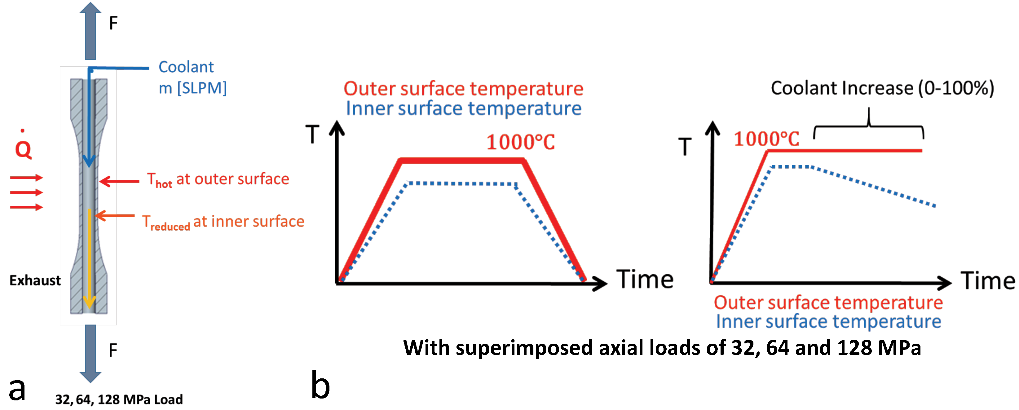
- Next, consider the influence of internal flow on the TGO strain response during thermal ramping. During thermal cycling, the surface heating by the radiation furnace introduces a transient thermal gradient over the specimen wall, which—without internal cooling—would vanish during hold at high temperature. The transient thermal gradient results in a delay of TGO strain response with respect to the surface temperature. Superposing an internal cooling air flow increases the time lag in strain response, which is visible when comparing the strain evolution at thermal ramp up in Figure 2f with that in Figure 2d,e.
4. Conclusions
- Quantifying the change in tensile strain magnitude at high temperature due to variable applied mechanical loading;
- Quantifying the non-linear in plane and out of plane TGO strain variation due to increased internal cooling flow rates;
- Demonstrating the competing nature of external mechanical loading and the effectiveness of internal cooling flow rates, suggesting that tuning local internal flow rates across a turbine blade could mitigate potential high tensile strains at operating temperatures.
Author Contributions
Funding
Conflicts of Interest
Appendix A


References
- Dorfman, M.; Stapgens, M.; Medrano, J.; Sporer, D. Takeoff with advanced coatings: Improving thermal protection through new material solutions. Sulzer Tech. Rev. 2013, 3, 8–12. [Google Scholar]
- Reed, R. The Superalloys: Fundamentals and Applications; Cambridge University Press: Cambridge, UK, 2006. [Google Scholar]
- Padture, N.P.; Gell, M.; Jordan, E.H. Thermal barrier coatings for gas-turbine engine applications. Science 2002, 296, 280–284. [Google Scholar] [CrossRef] [PubMed]
- Busso, E.; Evans, H.; Qian, Z.; Taylor, M. Effects of breakaway oxidation on local stresses in thermal barrier coatings. Acta Mater. 2010, 58, 1242–1251. [Google Scholar] [CrossRef]
- Evans, A.; Mumm, D.; Hutchinson, J.; Meier, G.; Pettit, F. Mechanisms controlling the durability of thermal barrier coatings. Prog. Mater. Sci. 2001, 46, 505–553. [Google Scholar] [CrossRef]
- Eberl, C.; Wang, X.; Gianola, D.S.; Nguyen, J.T.D.; He, M.Y.; Evans, A.G.; Hemkerz, K.J. In situ measurement of the toughness of the interface between a thermal barrier coating and a Ni alloy. Am. Ceram. Soc. 2011, 94, 120–127. [Google Scholar] [CrossRef]
- Gell, M.; Eric, J.; Krishnakumar, V.; McCarron, K.; Barber, B.; Sohn, Y.H.; Tolpygo, V.K. Bond strength, bond stress and spallation mechanisms of thermal barrier coatings. Surf. Coat. Technol. 1999, 120, 53–60. [Google Scholar] [CrossRef]
- Harvey, M.; Courcier, C.; Maurel, V.; Rémy, L. Oxide and TBC spallation in β-NiAl coated systems under mechanical loading. Surf. Coat. Technol. 2008, 203, 432–436. [Google Scholar] [CrossRef]
- Karlsson, A.M.; Hutchinson, J.; Evans, A. The displacement of the thermally grown oxide in thermal barrier systems upon temperature cycling. Mater. Sci. Eng. A 2003, 351, 244–257. [Google Scholar] [CrossRef] [Green Version]
- Karlsson, A.M.; Hutchinson, J.; Evans, A. A fundamental model of cyclic instabilities in thermal barrier systems. J. Mech. Phys. Solids 2002, 50, 1565–1589. [Google Scholar] [CrossRef] [Green Version]
- Lipkin, D.; Clarke, D. Measurement of the stress in oxide scales formed by oxidation of alumina-forming alloys. Oxid. Met. 1996, 45, 267–280. [Google Scholar] [CrossRef]
- Schulz, U.; Leyens, C.; Fritscher, K.; Peters, M.; Saruhan-Brings, B.; Lavigne, O.; Dorvaux, J.M.; Poulain, M.; Mévrel, R.; Caliez, M. Some recent trends in research and technology of advanced thermal barrier coatings. Aerosp. Sci. Technol. 2003, 7, 73–80. [Google Scholar] [CrossRef]
- Marino, K.A.; Hinnemann, B.; Carter, E.A. Inaugural article by a recently elected academy member: From the cover: Atomic-scale insight and design principles for turbine engine thermal barrier coatings from theory. Proc. Natl. Acad. Sci. USA 2011, 108, 5480. [Google Scholar] [CrossRef]
- Wright, P.K. Influence of cyclic strain on life of a PVD TBC. Mater. Sci. Eng. A 1998, 245, 191–200. [Google Scholar] [CrossRef]
- Traeger, F.; Vaßen, R.; Rauwald, K.H.; Stöver, D. Thermal cycling setup for testing thermal barrier coatings. Adv. Eng. Mater. 2003, 5, 429–432. [Google Scholar] [CrossRef]
- Vaßen, R.; Cernuschi, F.; Rizzi, G.; Scrivani, A.; Markocsan, N.; Östergren, L.; Kloosterman, A.; Mevrel, R.; Feist, J.; Nicholls, J. Recent activities in the field of thermal barrier coatings including burner rig testing in the European Union. Adv. Eng. Mater. 2008, 10, 907–921. [Google Scholar] [CrossRef]
- Drexler, J.M.; Aygun, A.; Li, D.; Vaben, R.; Steinke, T.; Padture, N.P. Thermal-gradient testing of thermal barrier coatings under simultaneous attack by molten glassy deposits and its mitigation. Surf. Coat. Technol. 2010, 204, 2683–2688. [Google Scholar] [CrossRef]
- Kitazawa, R.; Kakisawa, H.; Kagawa, Y. Anisotropic TGO morphology and stress distribution in EB-PVD Y2O3-ZrO2 thermal barrier coating after in-phase thermo-mechanical test. Surf. Coat. Technol. 2014, 238, 68–74. [Google Scholar] [CrossRef]
- Bartsch, M.; Marci, G.; Mull, K.; Sick, C. Fatigue testing of ceramic thermal barrier coatings for gas turbine blades. Adv. Eng. Mater. 1999, 1, 127–129. [Google Scholar] [CrossRef]
- Bartsch, M.; Baufeld, B.; Dalkilic, S.; Chernova, L.; Heinzelmann, M. Fatigue cracks in a thermal barrier coating system on a superalloy in multiaxial thermomechanical testing. Int. J. Fatigue 2008, 30, 211–218. [Google Scholar] [CrossRef]
- Hernandez, M.T.; Karlsson, A.M.; Bartsch, M. On TGO creep and the initiation of a class of fatigue cracks in thermal barrier coatings. Surf. Coat. Technol. 2009, 203, 3549–3558. [Google Scholar] [CrossRef] [Green Version]
- Hernandez, M.T.; Cojocaru, D.; Bartsch, M.; Karlsson, A.M. On the opening of a class of fatigue cracks due to thermo-mechanical fatigue testing of thermal barrier coatings. Computat. Mater. Sci. 2011, 50, 2561–2572. [Google Scholar] [CrossRef] [Green Version]
- Siddiqui, S.F.; Knipe, K.; Manero, A.; Meid, C.; Wischek, J.; Okasinski, J.; Almer, J.; Karlsson, A.M.; Bartsch, M.; Raghavan, S. Synchrotron X-ray measurement techniques for thermal barrier coated cylindrical samples under thermal gradients. Rev. Sci. Instrum. 2013, 84, 083904. [Google Scholar] [CrossRef] [PubMed]
- Knipe, K.; Manero, A., II; Siddiqui, S.F.; Meid, C.; Wischek, J.; Okasinski, J.; Almer, J.; Karlsson, A.M.; Bartsch, M.; Raghavan, S. Strain response of thermal barrier coatings captured under extreme engine environments through synchrotron X-ray diffraction. Nat. Commun. 2014, 5, 4559. [Google Scholar] [CrossRef] [PubMed] [Green Version]
- Manero, A., II; Sofronsky, S.; Knipe, K.; Meid, C.; Wischek, J.; Okasinski, J.; Almer, J.; Karlsson, A.M.; Raghavan, S.; Bartsch, M. Monitoring local strain in a thermal barrier coating system under thermal mechanical gas turbine operating conditions. JOM 2015, 67, 1528–1539. [Google Scholar] [CrossRef]
- Weyant, C.; Almer, J.; Faber, K. Through-thickness determination of phase composition and residual stresses in thermal barrier coatings using high-energy X-rays. Acta Mater. 2010, 58, 943–951. [Google Scholar] [CrossRef]
- Li, C.; Jacques, S.; Chen, Y.; Xiao, P.; Beale, A.; di Michael, M.; Markossan, N.; Nylen, P.; Cernik, R. Precise strain profile measurement as a function of depth in thermal barrier coatings using high energy synchrotron X-rays. Scr. Mater. 2016, 113, 122–126. [Google Scholar] [CrossRef] [Green Version]
- Welzel, U.; Ligot, J.; Lamparter, P.; Vermeulenb, A.C.; Mittemeijera, E.J. Stress analysis of polycrystalline thin films and surface regions by X-ray diffraction. J. Appl. Crystallogr. 2005, 38, 1–29. [Google Scholar] [CrossRef] [Green Version]
- Gladden, J.; So, J.H.; Maynard, J.; Saxe, P.; Page, Y.L. Reconciliation of ab initio theory and experimental elastic properties of Al2O3. Appl. Phys. Lett. 2004, 85, 392–394. [Google Scholar] [CrossRef]
- Manns, T.; Scholtes, B. DECcalc-A program for the calculation of diffraction elastic constants from single crystal coefficients. Mater. Sci. Forum Trans. Tech. Publ. 2011, 681, 417–419. [Google Scholar] [CrossRef]
- Whitaker, S. Forced convection heat transfer correlations for flow in pipes, past flat plates, single cylinders, single spheres, and for flow in packed beds and tube bundles. AIChE J. 1972, 18, 361–371. [Google Scholar] [CrossRef]
- Abraham, J.; Sparrow, E.; Tong, J. Heat transfer in all pipe flow regimes: laminar, transitional/intermittent, and turbulent. Int. J. Heat Mass Transf. 2009, 52, 557–563. [Google Scholar] [CrossRef]


© 2018 by the authors. Licensee MDPI, Basel, Switzerland. This article is an open access article distributed under the terms and conditions of the Creative Commons Attribution (CC BY) license (http://creativecommons.org/licenses/by/4.0/).
Share and Cite
Manero, A.; Knipe, K.; Wischek, J.; Meid, C.; Okasinski, J.; Almer, J.; Karlsson, A.M.; Bartsch, M.; Raghavan, S. Capturing the Competing Influence of Thermal and Mechanical Loads on the Strain of Turbine Blade Coatings via High Energy X-rays. Coatings 2018, 8, 320. https://doi.org/10.3390/coatings8090320
Manero A, Knipe K, Wischek J, Meid C, Okasinski J, Almer J, Karlsson AM, Bartsch M, Raghavan S. Capturing the Competing Influence of Thermal and Mechanical Loads on the Strain of Turbine Blade Coatings via High Energy X-rays. Coatings. 2018; 8(9):320. https://doi.org/10.3390/coatings8090320
Chicago/Turabian StyleManero, Albert, Kevin Knipe, Janine Wischek, Carla Meid, John Okasinski, Jonathan Almer, Anette M. Karlsson, Marion Bartsch, and Seetha Raghavan. 2018. "Capturing the Competing Influence of Thermal and Mechanical Loads on the Strain of Turbine Blade Coatings via High Energy X-rays" Coatings 8, no. 9: 320. https://doi.org/10.3390/coatings8090320