Article

Microstructure and Corrosion Resistance of WC-Based Cermet/Fe-Based Amorphous Alloy Composite Coatings

1
National Engineering Laboratory for Modern Materials Surface Engineering Technology, Guangdong Institute of New Materials, Guangzhou 510651, China
2
The Key Lab of Guangdong for Modern Surface Engineering Technology, Guangdong Institute of New Materials, Guangzhou 510651, China
*
Author to whom correspondence should be addressed.
Coatings 2018, 8(11), 393; https://doi.org/10.3390/coatings8110393
Submission received: 2 September 2018 / Revised: 30 October 2018 / Accepted: 1 November 2018 / Published: 6 November 2018

Abstract

:
There is an urgent need to improve the corrosion resistance of WC-based cermet coatings in different corrosive environments. The main objective of this work was to investigate the microstructure and evaluate the corrosion resistance in neutral, acidic, and alkaline electrolytes of the WC-based cermet/Fe-based amorphous alloy composite coating. Thus, a composite coating of WC–CoCr/Fe-based amorphous alloy and a single WC–CoCr coating were fabricated using the high-velocity oxygen fuel (HVOF) process. The phase composition, microstructure of the original powders, and as-sprayed coatings were studied. The detailed interface information between different compositions of the composite coating was observed by high-resolution transmission electron microscopy (HRTEM). The corrosion resistance of the coatings was studied comparatively by electrochemical tests in 3.5 wt % NaCl, 1 M HCl and 1 M NaOH solutions, respectively. Results showed that the composited coating had a dense layered structure with a composition of WC, Fe-based amorphous alloy, and small amount of W2C. It was revealed that obvious inter-diffusion exists between the interfaces of tungsten carbide/Co, Cr binder and WC–CoCr/Fe-based amorphous alloy. The electrochemical test results showed that the composite coating displayed better corrosion resistance than single WC–CoCr coating both in 3.5 wt % NaCl solution and in 1 M NaOH solution.

1. Introduction

As a replacement of hard chrome plating, thermal-sprayed WC-based cermet coatings have been widely used in several industries, such as aerospace, automobile, and energy, due to their excellent performance of wear resistance [1,2,3]. The hard WC particles in the coatings provide hardness and wear resistance while the metal binder (CoCr, NiCr, Ni, Co, etc.) gives the necessary coating toughness [4]. In comparison with air plasma spray (APS), high-velocity oxygen fuel (HVOF) spraying has been well proven for the deposition of WC-based cermet coatings due to its exceptional characteristics, such as the higher velocities and the lower flame temperatures [5], which results in less decomposition of WC during spraying [6,7].
As the WC-based cermet coatings have been widely used, it is realized that the corrosion resistance becomes increasingly important besides wear resistance because the potential service environments for these WC-based cermet coated components are inherently corrosive in nature. However, the corrosion resistance of WC-based cermet coatings is not so desirable [8]. In recent years, optimization of processing parameters and incorporating anti-corrosive materials have been tried to improve the corrosion resistance. References [8,9] reported that minimization or partial elimination of intrinsic defects, such as porosities, microcracks and oxide phase by optimization of processing parameters, helped to improve the corrosion resistance. Hong et al. [10] prepared nanostructured WC–10Co–4Cr coating by adjusting HVOF process, and the coating exhibited better corrosion resistance in 3.5% NaCl solution. Investigation by Basak et al. [11] showed nanostructured WC–Co coatings (with and without Al) exhibited better corrosion in comparison with micron-sized coating. Reference [12] reported that the addition of TiC improves the corrosion resistance of WC–Co in 1 mol L−1 NaOH compared with the base alloy. Additionally, some work proved that the addition of Ni enhanced the corrosion resistance and oxidation resistance [13,14]. Research by Sutthiruangwong et al. [15] found that adding Cr2C3 significantly reduced the current density.
In recent years, amorphous alloys, especially Fe-based amorphous alloys, have gained wide attention owing to their inherent good properties such as high crystallization temperature, good corrosion and wear resistance, and relatively low material cost [16,17,18]. Fe-based amorphous alloys, therefore, could be chosen as additional anti-corrosive materials to improve corrosion resistance of WC-based cermet. Moreover, HVOF has been regarded as one of the suitable techniques to prepare Fe-based amorphous alloy coatings [19,20,21,22]. An investigation, furthermore, showed that the addition of Fe-based amorphous alloy improved the corrosion resistance of WC coating in 3.5% NaCl [23]. However, little has been presented regarding the detailed microstructures and comprehensive corrosion properties of WC-based cermet and Fe-based amorphous alloy composite coatings. Therefore, the present study is conducted to determine the microstructure, especially the interfaces of different composition of HVOF-sprayed WC–CoCr/Fe-based amorphous alloy composite coatings, and their corrosion resistance in neutral, acidic, and alkaline electrolytes, respectively.

2. Materials and Methods

2.1. Materials and Parameters of HVOF

A conventional, spherical, agglomerated, and sintered WC–10 wt %Co–4 wt %Cr powder with a nominal size distribution of 10–38 μm was obtained from GTV Verschleißschutz GmbH (Luckenbach, Germany). A commercial Fe-based amorphous powder (SHS7170) with a nominal size range of 15–53 μm was obtained from Nanosteel company Inc., Providence, RI, USA. The nominal alloy composition was 20 wt % Cr, 10 wt % W, 5 wt % B, 5 wt % Mn, 5 wt % Mo, 2 wt % C, 2 wt % Si with the balance being Fe. WC–CoCr and Fe-based amorphous powders with the weight ratio of 65:35 were homogeneously mixed by a two-dimension mixer before spraying. A commercial HVOF spraying system (GTV HVOF K2, GTV Verschleißschutz GmbH, Luckenbach, Germany) was used for thermal spraying with WC–CoCr power and the mixed powder. The coating was deposited onto 304 stainless steel substrates with a dimension of 30 × 50 × 4 mm3. Before spraying, the substrate was degreased with acetone and grit blasted with 46 mesh alumina grit to give a surface roughness of Ra 2–3 μm. The used process parameters, which is based on the preliminary parameter optimization, are listed in Table 1.

2.2. Microstructural Characterization

The phase composition of both the as-received powder and the as-sprayed coatings was identified by an X-ray diffractometer (XRD, D/MAX-IIIA, Riguka, Tokyo, Japan). Surface morphology, cross sectional microstructure of the as-received powders, as-sprayed coatings and the corroded coatings after electrochemical test were observed on a scanning electronic microscope (SEM, Nova nano 450, FEI, Hillsbore, OR, USA). The chemical composition of both the as-spray coatings and the corroded coatings was determined by energy dispersive spectroscope (EDS, Octame plus, EDAX Inc, Draper, UT, USA). Finer-scale microstructural features of the composite coatings were performed using the combination of transmission electron microscopy (TEM, Titan Themis, 200, FEI, Eindhoven, Netherlands) and EDS operated at 200 kV.

2.3. Corrosion Behavior

Corrosion behavior was investigated by the potentiodynamic polarization tests. Prior to electrochemical tests, the specimens were mechanically polished, then degreased in ethanol, washed in distilled water, and dried in air. 3.5 wt % NaCl solutions, 1 M HCl solutions and 1 M NaOH solutions were prepared from reagent grade chemicals and distilled water was used as electrolytes. Electrochemical test was conducted in a three-electrode cell using a platinum counter electrode and saturated calomel electrode (SCE) reference electrode. Potentiodynamic polarization curves were recorded at a potential scanning rate of 0.5 mV s−1 from an initial potential of 400 mV below the open circuit potential (OCP) up to 1200 mV above the OCP after immersing the specimens for about 60 min when the open circuit potentials became almost steady. Electrochemical parameters such as corrosion potential (Ecorr), corrosion current density (icorr) and polarization resistance (Rp) were calculated by using CView software (2.3d).

3. Results and Discussion

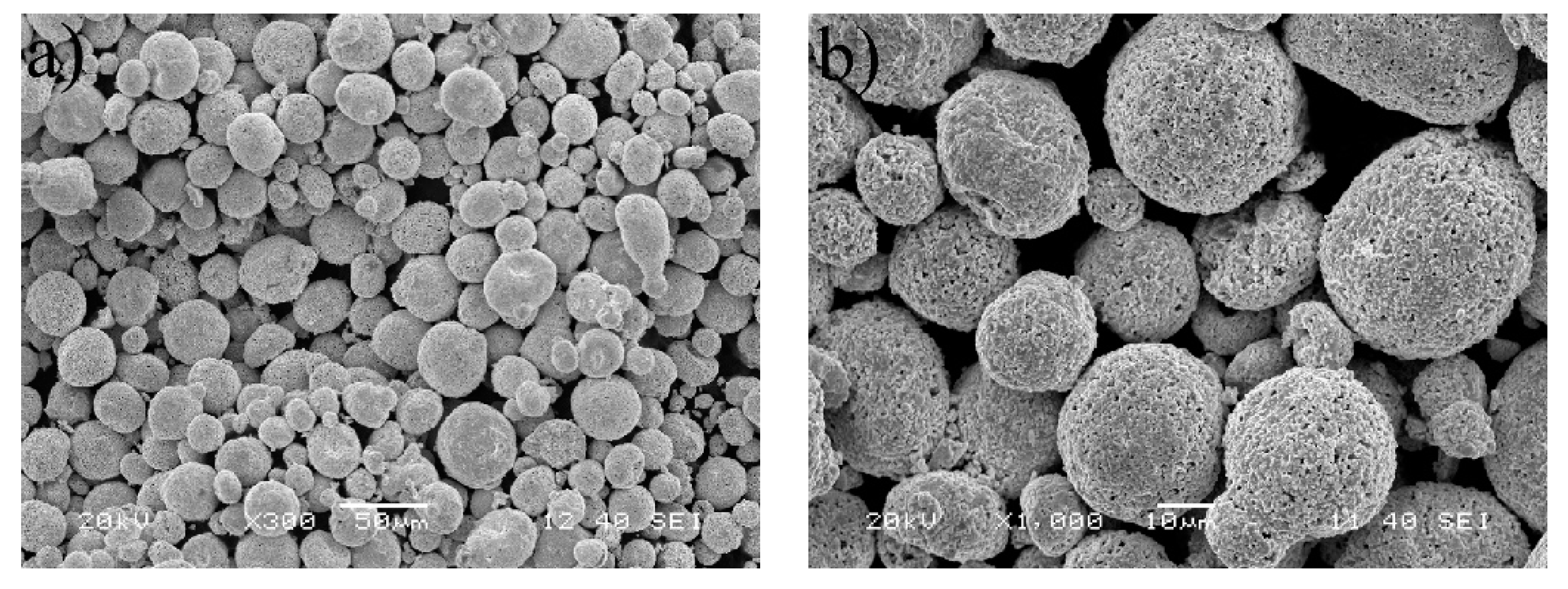
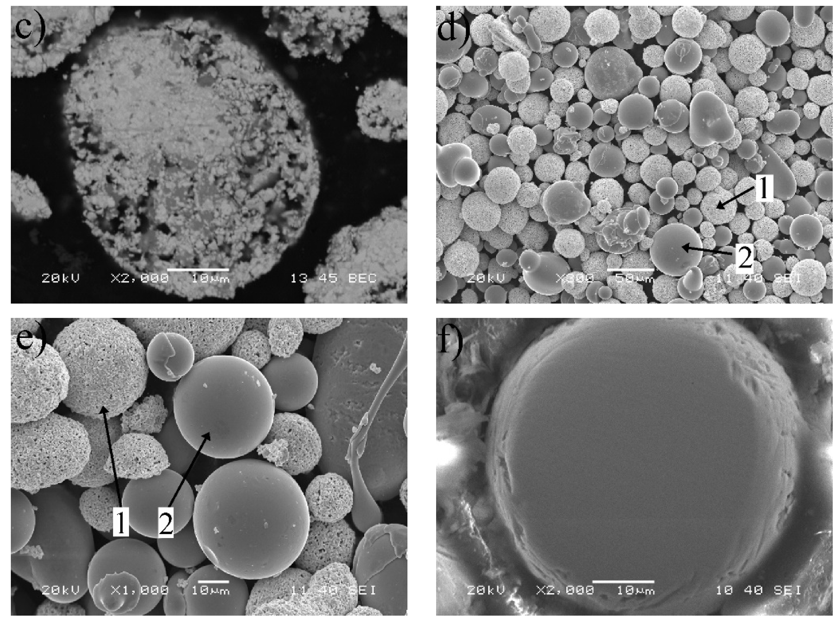
3.1. Powder Morphology

SEM images from morphology of different feedstock powders are shown in Figure 1. As illustrated in Figure 1a,c, the WC–CoCr powder particles show typical agglomerated and sintered particles features with a spherical morphology and highly porous surface, and lots of holes are within the spherical particles. According to Figure 1d,f, the mixed powder is relatively uniform, among which the Fe-based amorphous particles (Label 2) display a spherical morphology with dense surface and interior, which is a representative morphology of gas atomized particles.

3.2. Characterization of the Coatings

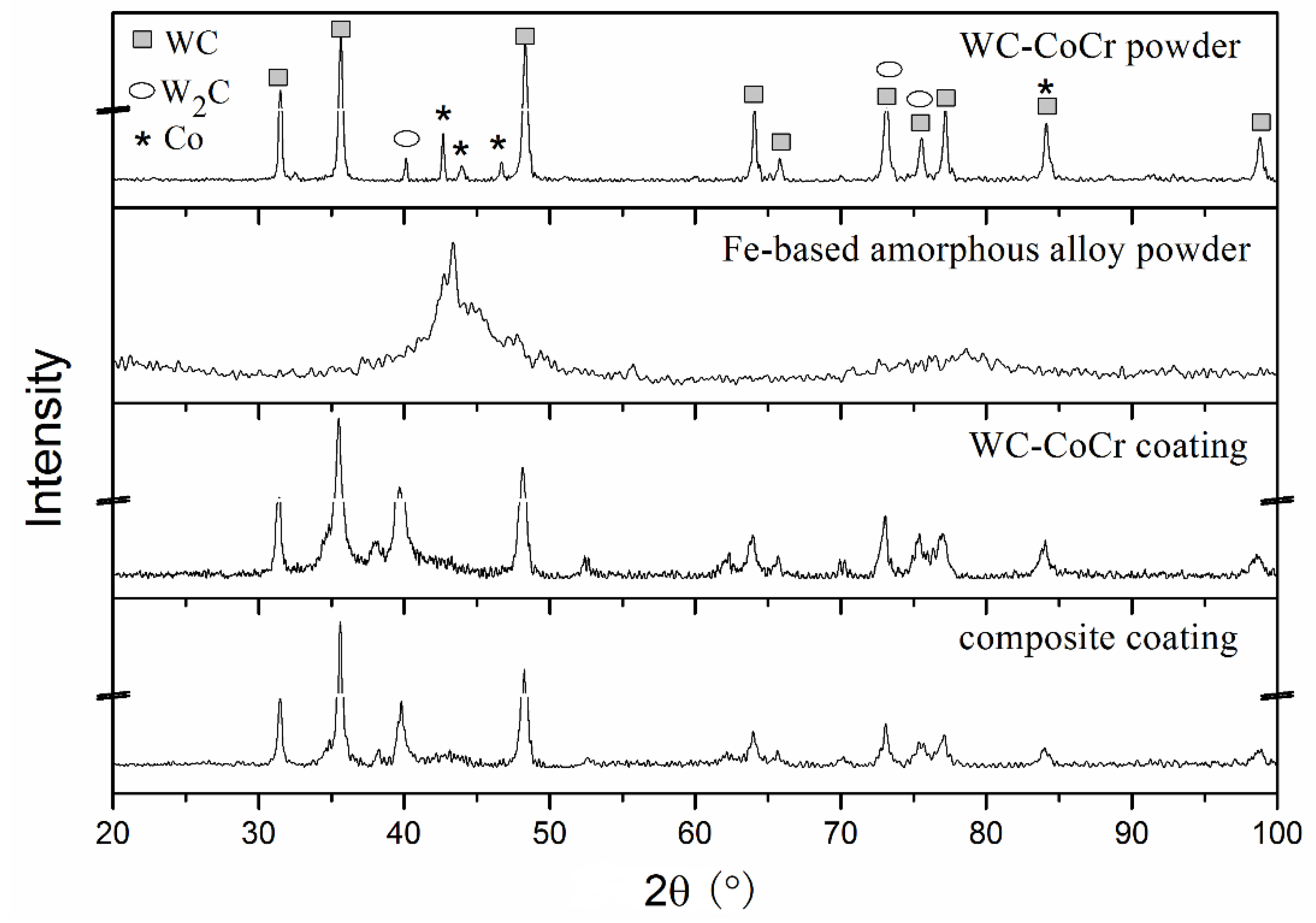
3.2.1. Phase Constitution

Figure 2 displays XRD patterns of the original powders of WC–CoCr and Fe-based amorphous alloy as well as that of the as-sprayed coatings. The WC–CoCr powder is mostly WC phase with a small amount of W2C phase and of unalloyed Co phase. The Fe-based amorphous powder shows the typical broad diffraction peaks of amorphous materials. The WC–CoCr coating contains more W2C phase than that in the original powder, which means decomposition of small amount of WC phase occurs during the HVOF spray process [4,6]. The diffraction peaks of Co phase in the original WC–CoCr powder become wide amorphous peaks in the WC–CoCr coating which may be attributed to the reactions between WC and Co. The diffraction peaks of the composite coating are similar to that of WC–CoCr coating, and weak diffraction signal of amorphous phase is detected between 40° and 45°.

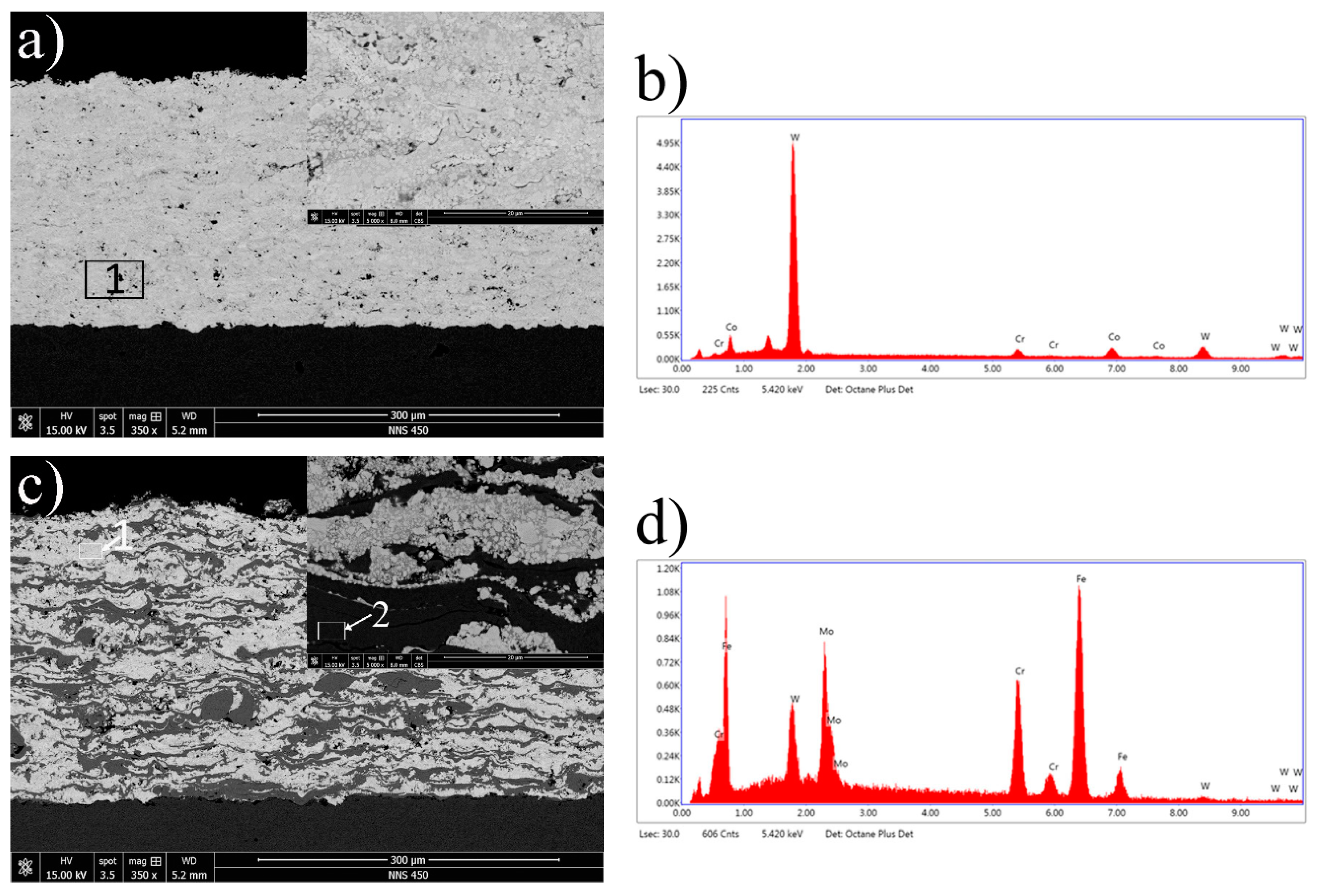
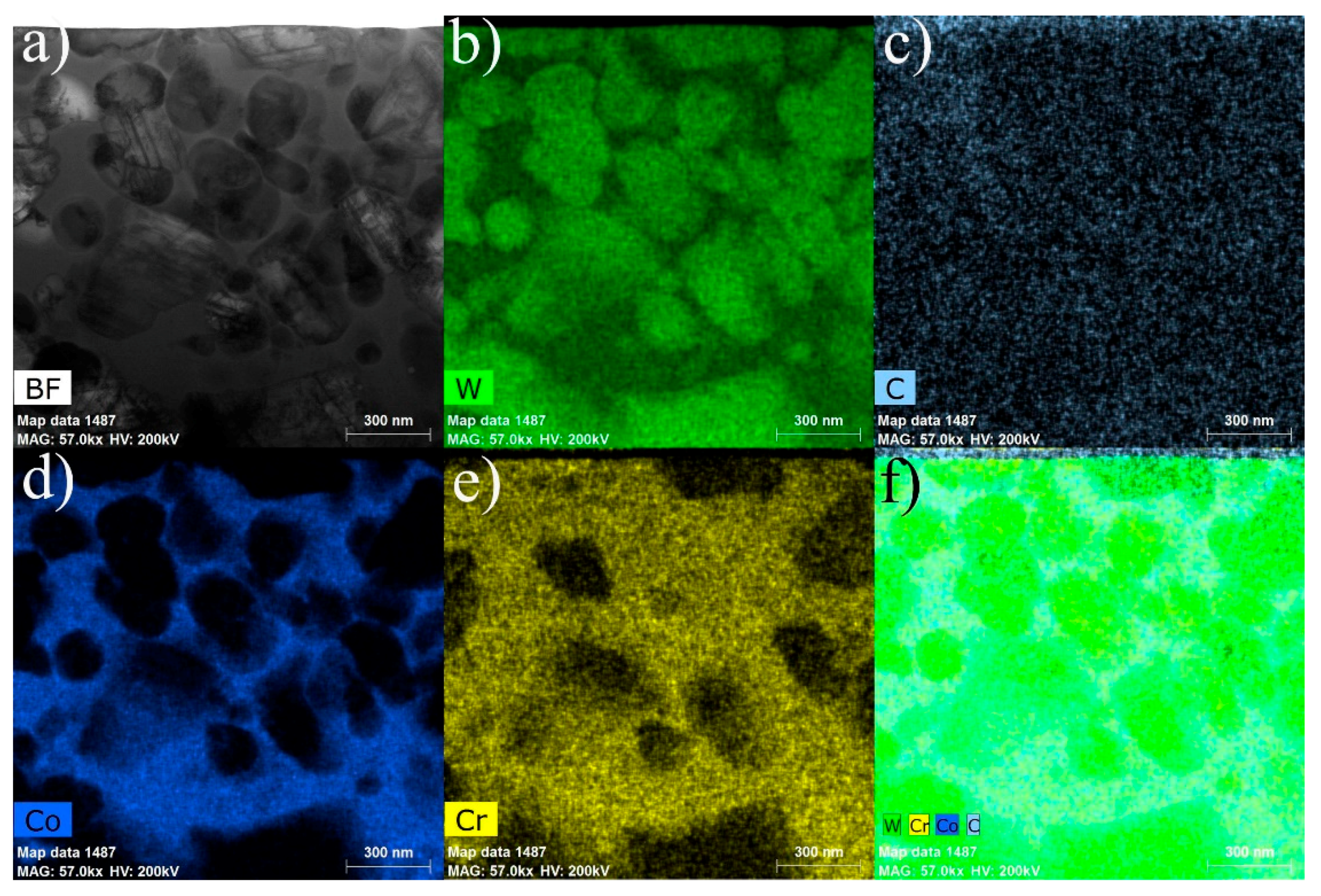
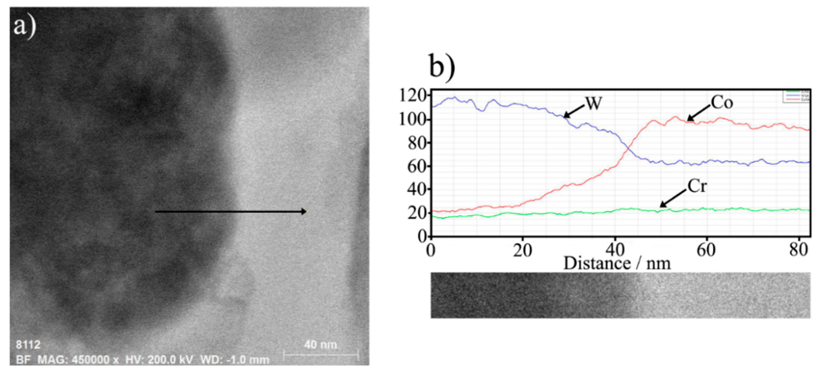
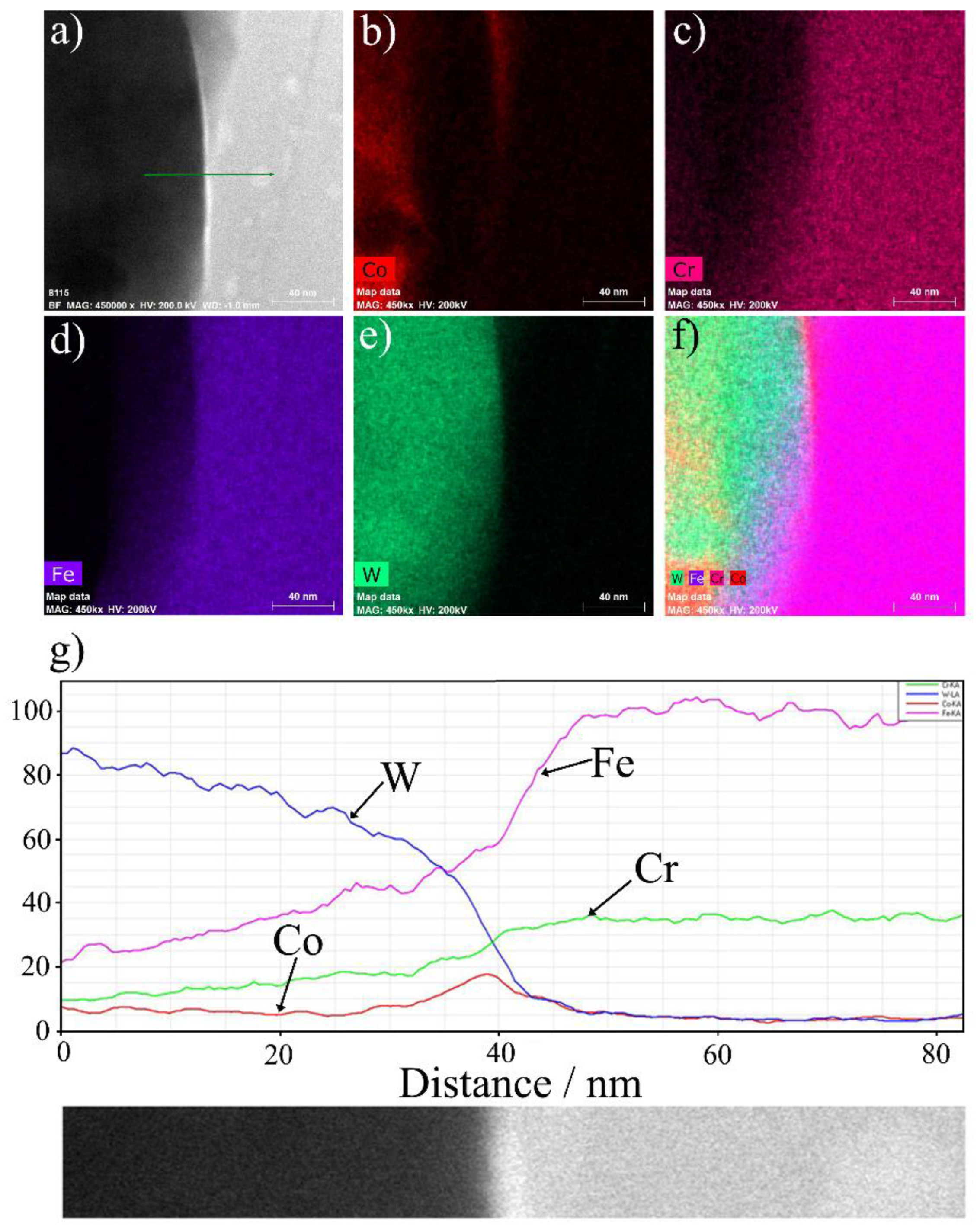
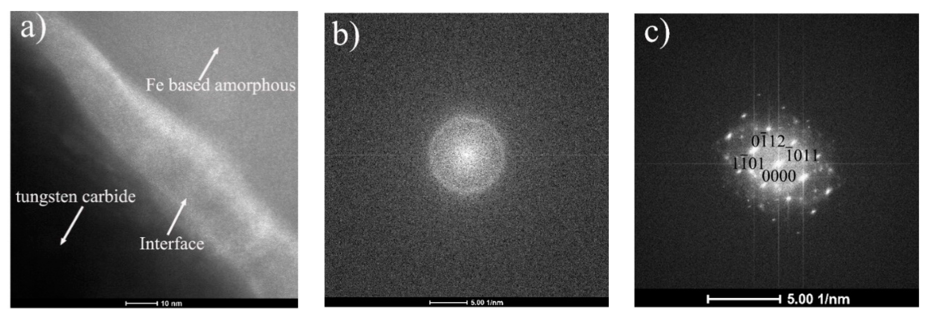
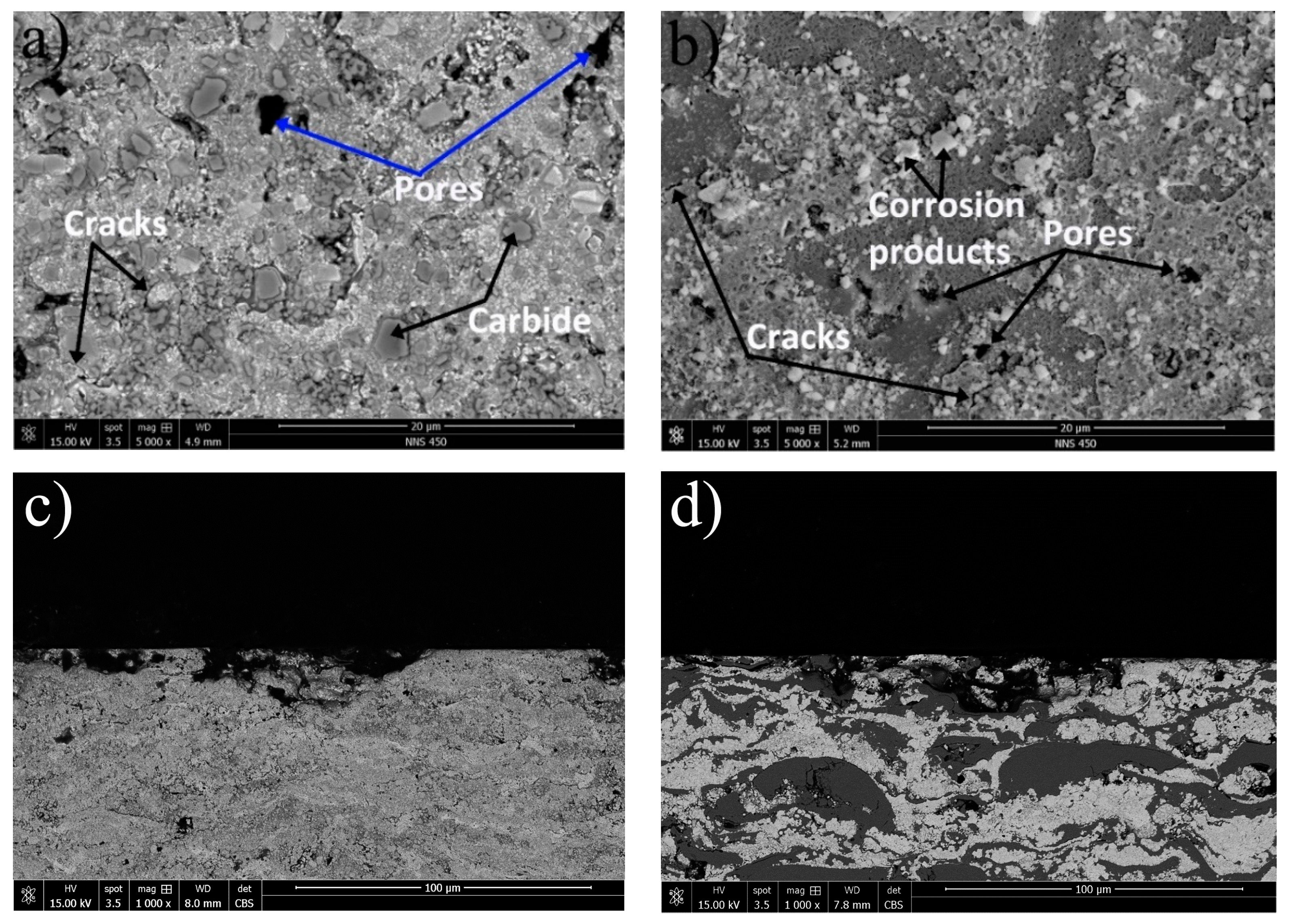
3.2.2. Microstructure

Figure 3 shows the microstructure of the as-sprayed coatings on a polished cross-section. It is evident from Figure 3a that the WC–CoCr coating is a dense layer structure and well-bonded to the substrate. Despite there are some pores, the average porosity of the coating is less than 2%. A similar morphology was observed in other investigations [12,20,21,22,23]. EDS analysis on area 1 indicated in Figure 3a shows that the coating contains W, Co, and Cr. The composite coating also shows a compact lamellar structure, which is different from pure WC–CoCr coatings and pure Fe-based amorphous coatings fabricated by HVOF [24] due to the different atomic number of W and Fe. The average porosity fraction in the composite coating was approximately 1.0%. EDS analysis on area1 indicated in Figure 3c displays a similar result in WC–CoCr coatings (the result is omitted here), confirming that the bright lamellae are WC–CoCr, while the dark lamellae are identified as Fe-based amorphous alloy, as shown in Figure 3d. A similar morphology was observed in other reports [25,26].
TEM and HRTEM were carried out to obtain more detailed information about the microstructure of the composite coating in the present study. Figure 4 displays a bright field TEM image and EDS mapping analysis of WC–CoCr area of the as-sprayed composite coating. It can be observed clearly that some irregular shaped particles distributed randomly as shown in Figure 4a. According to Figure 4b–e and the XRD results (Figure 2), it can be deduced that the irregular particles are tungsten carbides which are sounded by Co and Cr. Besides, inter-diffusion exits between tungsten carbides and Co, Cr.
To further reveal the W, Co, and Cr distribution around the interface between tungsten carbide and binder, an element line scan is conducted across the interface, as shown in Figure 5. The line scanning position is indicated by the arrow line shown in Figure 5a. From the element scanning profile shown in Figure 5b, it can be clearly seen that the tungsten content gradually decreases and cobalt content gradually increases from the tungsten carbide particle side, going through the interface to the binder side, while the chromium content keeps constant, confirming that an inter-diffusion of W, Co and Cr happened during the HVOF process, and the diffusion of Cr is more uniform than W and Co.
Figure 6 presents a bright field TEM image, EDS mapping analysis and an element line scan of the interface between WC-based cermet area and Fe-based amorphous alloy area. Co distributes mostly on WC-based cermet side around tungsten carbide, as shown in Figure 6b. Most of Cr and Fe are detected on the Fe-based amorphous alloy side and small amount are detected on the WC-based cermet side, as shown in Figure 6c,d. From the element line scan result shown in Figure 6g, it can be clearly seen that the W content gradually decreases, and Fe and Cr contents gradually increases from the WC-based cermet side, going through the interface to the Fe-based amorphous alloy side, while the cobalt content keeps constant on both sides except the increase at the interface, which means that an inter-diffusion exits between WC-based cermet and Fe-based amorphous alloy, and a relatively small amount of Co binder diffuses to both tungsten carbide particle side, which is in agreement with the results of Figure 5, and Fe-based amorphous alloy side.
Figure 7 exhibits the TEM bright field image of an enlarged interface which contains WC-based cermet area, interface, and Fe-based amorphous alloy area. Selected area electron diffraction (SAED) patterns of WC-based cermet and amorphous alloy phase (indicated by arrows in Figure 7a) are shown in Figure 7b,c. As can be seen, there is an obvious interface in the range of 10–20 nm between WC-based cermet and Fe-based amorphous alloy, implying an inter-diffusion and good metallurgical bonding between WC-based cermet and Fe-based amorphous alloy. SAED pattern of WC-based cermet could be indexed as corresponds to the <110> zone axis of W2C phase, which is consistent with the XRD pattern. SAED pattern of Fe-based amorphous area shows the characteristics diffuse diffracting rings corresponding to a short-ordered material indicating that the results from the XRD are accurate, which means the Fe-based amorphous alloy powder do not crystallize during the HVOF process.

3.3. Electrochemical Corrosion Behavior

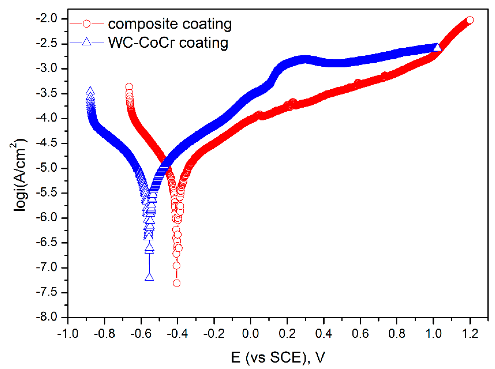
3.3.1. Electrochemical Corrosion Behavior in 3.5 wt % NaCl Solution

The potentiodynamic polarization curves of the as-sprayed coatings in 3.5 wt % NaCl solution are shown in Figure 8. The corresponding electrochemical values are listed in Table 2. It is evident that the curves exhibit similar polarization behavior. The Ecorr of the WC–CoCr coating and the composite coating are about −0.556 V and −0.404 V, respectively. The icorr of the composite coating is 5.57 × 10⁻⁶ A cm−2, which is obviously smaller than that of the WC–CoCr coating (3.86 × 10⁻⁵ A cm−2). The Rp value of the composite coating is 7399 Ω cm2, which is higher than that of the WC–CoCr coating (6755 Ω cm2). It is believed that the extent of corrosion is determined by the corrosion potential, the corrosion rate is determined by the corrosion current density [23], and the polarization resistance corresponds to corrosion resistance. Thus, the more positive Ecorr, the lower icorr and the higher Rp of the composite coating indicate a better corrosion resistance than the WC–CoCr coating. This can be attributed to the microstructure and chemical composition. From the microstructure, the composite coating displays a dense layer structure and a good bond of both the tungsten carbide/binder interface and the WC-based cermet/Fe-based amorphous alloy interface, as shown in Figure 5 and Figure 6. Regarding chemical composition, the addition of Fe-based amorphous alloy deduces the content of Co binder, which has relatively high corrosion rate [23,27]. Furthermore, both amorphous phase and WC matrix contain Cr, which is in favor of self-passivation. Meanwhile, the Mo, B and C in amorphous phase all contribute to enhancing the corrosion resistance [23,28].
To further understand the differences in corrosion resistance between the WC–CoCr coating and the composite coating, the surface and cross-section morphologies of the coatings were evaluated using SEM after electrochemical measurements in 3.5 wt % NaCl solution, as shown in Figure 9. Obvious corrosion happened, and some corrosion cracks and pores can be observed on the surface of the WC–CoCr coating. It is believed that the corrosion attack of the WC–CoCr coating is generally from the selective dissolution of the metallic matrix, which is more anodic than the WC particles [29]. In addition, with the matrix corrodes, the WC particles fall out and leave behind pores [30]. That is the reason for the formation of some corrosion pores. On the other side, the micropores in the original coating might become bigger owing to corrosion. However, it is hard to distinguish between the pores in the original coating and the pores caused by falling of WC particles. From the cross-section morphology, the corrosion happened near to surface. For the composite coating, pitting corrosion, corrosion cracks, pores and corrosion products were observed on the surface. The Fe-based amorphous area is clearly subjected to pitting corrosion. Research on Fe42.87Cr15.98Mo16.33C15.94B0.88 (at %) amorphous alloy coating on a 304 stainless steel showed that the Ecorr and the icorr of the coating are −0.472 V and 5.623 × 10⁻⁶ A cm−2 respectively in 3.5% NaCl solution, and no any obvious pitting corrosion happened after the electrochemical test [31]. Another investigation into a composite coating of the Fe-based amorphous above mentioned and WC–10Co–4Cr with a mass ratio of 1:3 on a mild steel exhibited that the Ecorr and the icorr of the coating are –0.65 V and 3.162 × 10⁻⁶ A cm−2 respectively in 3.5% NaCl solution, and no obvious indications of pitting corrosion and corrosion cracks after the electrochemical test [23]. In this case, both the Ecorr and the icorr are close to the reported results. However, the as-sprayed composite coating corroded after the electrochemical test that falls in line with the results. This may be attributed to the process parameters and coating chemical composition. Moreover, the cross-section morphologies display that the corrosion happened near to surface, no obvious further penetration of electrolyte can be observed.

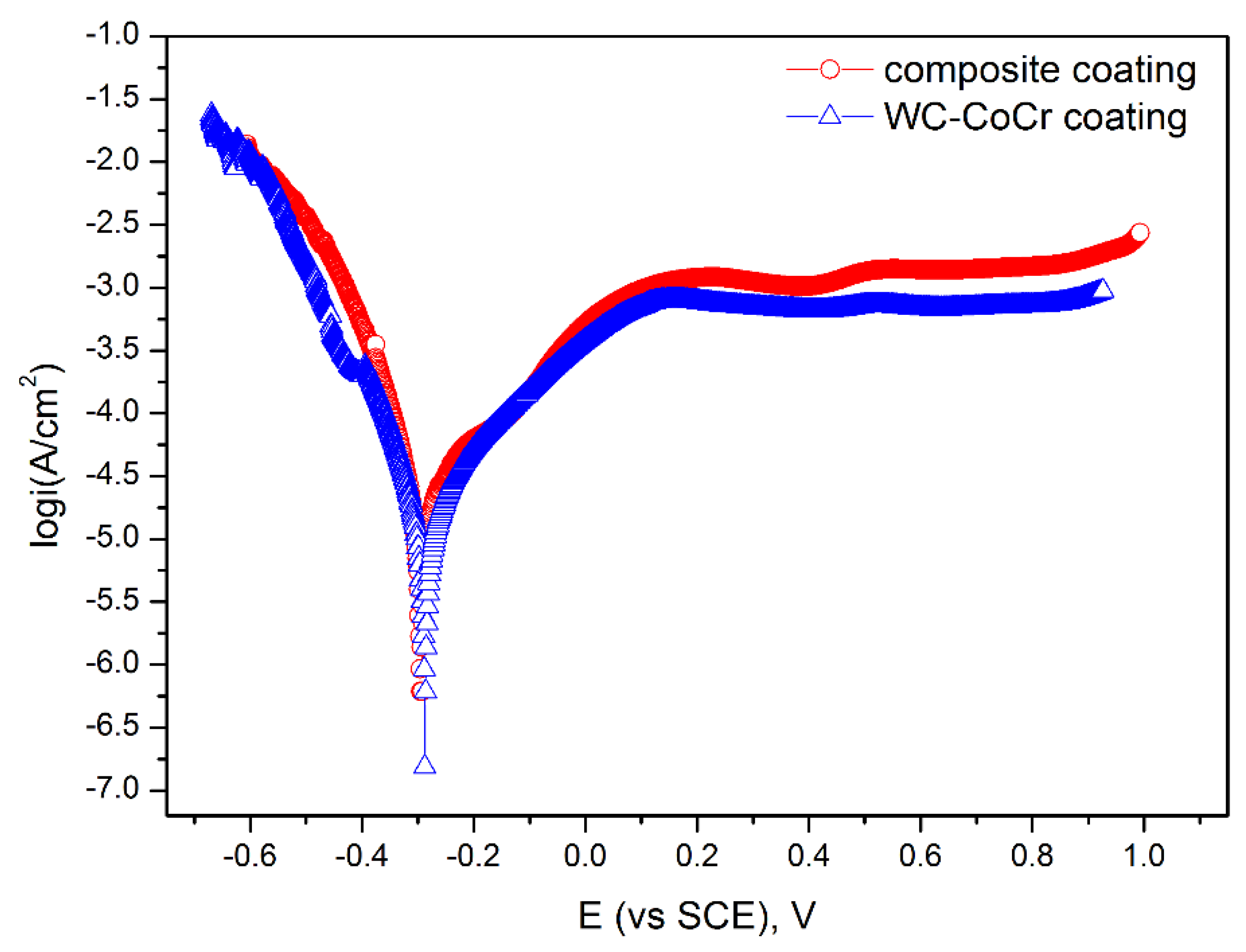
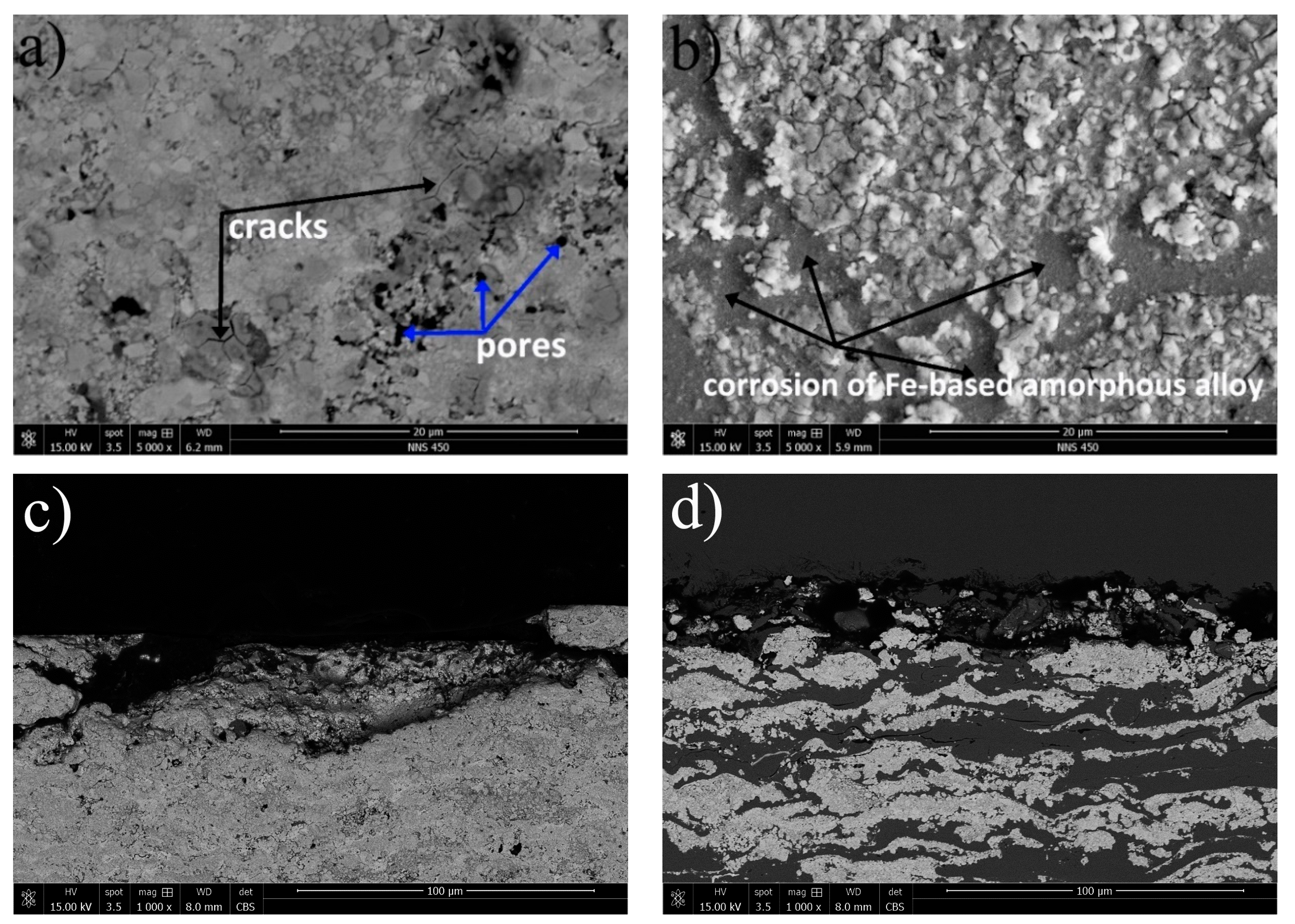
3.3.2. Electrochemical Corrosion Behavior in 1 M HCl Solution

The potentiodynamic polarization curves of the as-sprayed coatings in 1 M HCl solution are shown in Figure 10. The corresponding electrochemical values are listed in Table 3. These two curves show very similar behavior with a spontaneous passive stage, and the passive current densities (ipass) of the WC–CoCr coating and the composite coating are approximately 8.16 × 10⁻⁴ A cm−2 and 1.64 × 10⁻³ A cm−2 respectively. In addition, the composite coating exhibits a more negative Ecorr of −0.294 V than that of the WC–CoCr coating, i.e., −0.287 V, a higher icorr of 2.83 × 10⁻⁵ A cm−2 than that of the WC–CoCr coating, i.e., 1.68 × 10⁻⁵ A cm−2, and a lower Rp of 923 Ω cm2 than that of the WC–CoCr coating, i.e., 1549 Ω cm2, indicating that the corrosion resistance of composite coating is inferior to that of the WC–CoCr coating in 1 M HCl solution.
Unfortunately, the corrosion resistance of both the WC–CoCr coating and the composite coating declines rapidly in 1M HCl solution compared with their performance in 3.5% NaCl solution. Furthermore, as shown in Figure 11, lots of corrosion cracks and pores can be observed on the surface of the WC–CoCr coating, which means corrosion happened during the potentiodynamic polarization test. Similar morphology can be found in other literature [30,32]. For the composite coating, many cracks, corrosion products and pores can be found on the surface of WC–CoCr area, while no obvious cracks and pores are observed on the surface of the Fe-based amorphous alloy area, meaning the Fe-based amorphous alloy area of the composite coating exhibits general corrosion behavior in 1 M HCl solution. This form of corrosion was observed by an investigation of a composite coating fabricated with the powder mixture of Fe-based metallic glass, NiCr alloy and WC particle by HVOF thermal spray [33]. Moreover, research on Fe48Cr15Mo14C15B6Y2 amorphous alloy coating also showed the coating were spontaneously passivized in 1 M HCl solution and exhibited general corrosion behavior after the electrochemical measurement [24]. Based on the cross-section morphologies, the corrosion depth of both coatings are dozens of microns.
Compared to the results in 3.5% NaCl solution, the corrosion of WC–CoCr is accelerated, but the passivation of Fe-based amorphous alloys becomes stable in 1 M HCl solution. Nevertheless, the passivation is not sufficient for enhancing the corrosion resistance, so that the contribution given by the peculiar chemical composition and structural characteristic of amorphous alloy part in the composite coatings becomes less important.

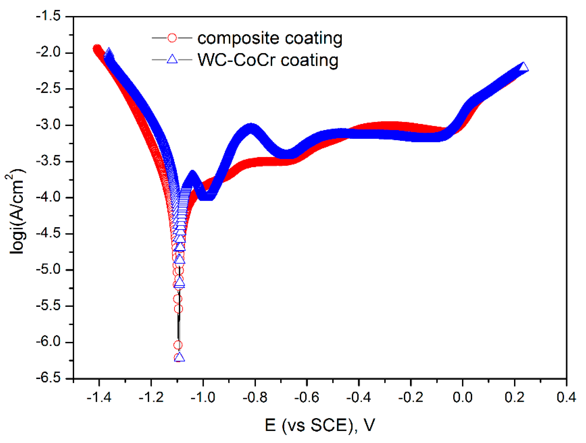
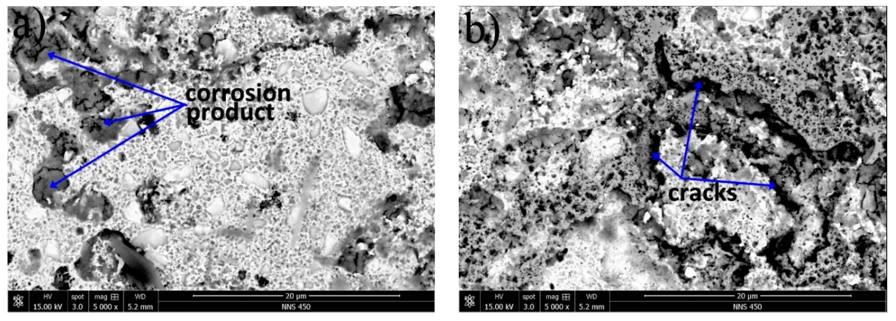
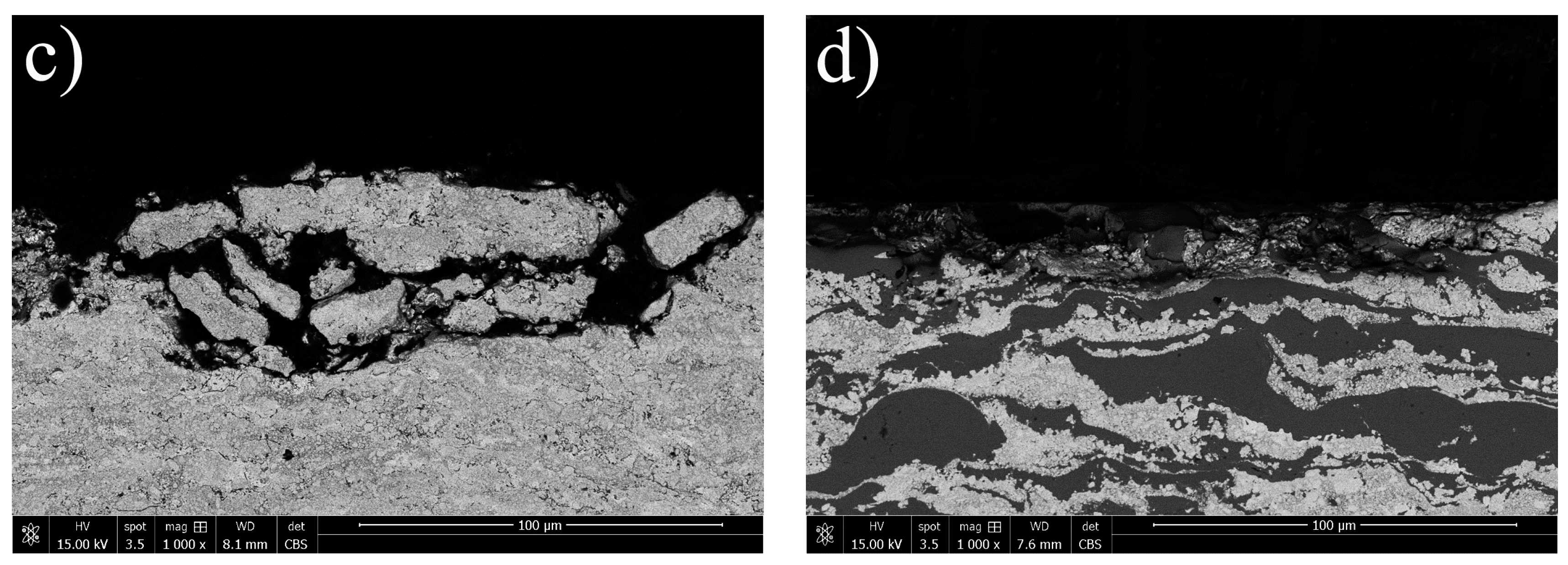
3.3.3. Electrochemical Corrosion Behavior in 1 M NaOH Solution

The potentiodynamic polarization curves of the as-sprayed coatings in 1 M NaOH solution are shown in Figure 12. The corresponding electrochemical values are listed in Table 4. These two coatings are spontaneously passivized with passive current density in the order of magnitude around 10−4 A cm−2 and wide passive region larger than 1.0 V (SCE). For the WC–CoCr coating, there are several fluctuations, implying a continuous process of activation and passivation [34], whereas the passivation of the composite coating is relatively stable. Nevertheless, although the Ecorr of the WC–CoCr coating are comparable to the composite coating, the icorr of WC–CoCr is higher than that of the composite coating. Generally, the icorr is an important parameter to evaluate the kinetic of corrosion reactions, and besides the corrosion rate is proportional to the corrosion current density measured via polarization [35]. That means the lower icorr led to the lower corrosion rate [36]. In addition, the Rp of the composite coating is higher than that of the WC–CoCr coating. Therefore, the corrosion resistance of the composite coating is superior to that of the WC–CoCr coating in 1 M NaOH solution.
The morphologies of the surfaces of the WC–CoCr coating and the composite coating after electrochemical measurement are shown in Figure 13. As can be seen, both coatings display a severely corrosive surface morphology. Lots of pores are caused by the corrosion of Co, Cr metal binder and subsequently fall out of WC particles and corrosion products (dark area in Figure 13a) composed of O, Na, W, Co, and Cr are observed on the surface of WC–CoCr coating. Many pitting pores with different sizes on both WC–CoCr area and Fe-based amorphous alloy area and obvious corrosion crack, as indicated by arrows in Figure 13b, can be found on the surface of the composite coatings. It is reported that WC is unstable in alkaline solution due to the detrimental local galvanic coupling at the interface [33]. In this case, the fluctuations shown in potentiodynamic polarization confirm this, and the serious surface corrosion further supports it. As for the composite coating, it is presumably attributed to the concentration of OH- increased continuously during the polarization process, due to the chemical reaction on cathode: O2 + 2H2O + 4e → 4OH. At the initial stage of the polarization process, the passive films can be formed. As the concentration of OH increases, the surface unsteady passive film of amorphous coating begins to dissolve [24,31]. That is the reason the composite coating displays a passivation platform with wide passive region, better corrosion resistance but a poor corrosion morphology. The cross-section morphology exhibits that the corrosion of the WC–CoCr coating is deeper than that of the composite coating. Similar to the test in 1 M HCl solution, the corrosion attack occurs and spreads to dozens of microns depth from the surface.

4. Conclusions

The microstructure and corrosion resistance of HVOF thermally sprayed WC–CoCr/Fe-based amorphous alloy were investigated. Microstructure and phase composition studies show that the composite coatings have a compact layered structure and contains WC, Fe-based amorphous alloy, and a small amount of W2C phase. Further observations find that there is inter-diffusion between tungsten carbide particles and Co, Cr binder, and an inter-diffusion area with a width range of 10–20 nm between WC–CoCr and Fe-based amorphous alloy.
The composite coating has better corrosion resistance in 3.5% NaCl and 1 M NaOH solution than single WC–CoCr coating, whereas the corrosion resistance of single WC–CoCr coating is superior to that of the composite coating in 1 M HCl.

Author Contributions

Conceptualization, L.X., J.S., C.D., M.L. and K.Z.; Investigation, L.X., J.S. and X.Z.; Methodology, X.Z.; Writing–Original Draft, L.X.; Writing–Review & Editing, L.X.

Funding

This work has been financially supported by Science and Technology Planning Project of Guangdong province (No. 2017A070701027), National Natural Science Foundation of China (No. 51771059), Natural Science Foundation of Guangdong Province (No. 2016A030312015), and GDAS’s Project of Science and Technology Development (No. 2017GDASCX-0202 and 2017GDASCX-0111).

Acknowledgments

The authors would like to appreciate Xiangwei Chen for her assistance and advice in English language editing.

Conflicts of Interest

The authors declare no conflict of interest.

References

  1. Agüero, A.; Camón, F.; De Blas, J.G.; Del Hoyo, J.C.; Muelas, R.; Santaballa, A.; Ulargui, S.; Vallés, P. HVOF-deposited WCCoCr as replacement for hard Cr in landing gear actuators. J. Therm. Spray Technol. 2011, 20, 1292–1309. [Google Scholar] [CrossRef] [Green Version]
  2. Lalit Thakura, N.A. Sliding and abrasive wear behavior of WC–CoCr coatings with different carbide sizes. J. Mater. Eng. Perform. 2013, 22, 574–583. [Google Scholar] [CrossRef]
  3. Fauchais, P.L.; Heberlein, J.V.R.; Boulos, M. Thermal Spray Fundamentals: From Powder to Part; Springer: Boston, MA, USA, 2014; p. 640. [Google Scholar]
  4. Brious, S.; Belmokre, K.; Debout, V.; Jacquot, P.; Conforto, E.; Touzain, S.; Creus, J. Corrosion behavior in artificial seawater of thermal-sprayed WC–CoCr coatings on mild steel by electrochemical impedance spectroscopy. J. Solid State Electrochem. 2012, 16, 633–648. [Google Scholar] [CrossRef]
  5. Oksa, M.; Turunen, E.; Suhonen, T.; Varis, T.; Simo-Pekka, H. Optimization and characterization of high velocity oxy-fuel sprayed coatings: Techniques, materials, and application. Coatings 2011, 1, 17–52. [Google Scholar] [CrossRef]
  6. Thiele, S.; Sempf, K.; Jaenicke-Roessler, K.; Berge, L.-M.; Spatzier, J. Thermophysical and microstructural studies on thermally sprayed tungsten carbide-cobalt coatings. J. Therm. Spray Technol. 2011, 20, 358–365. [Google Scholar] [CrossRef]
  7. Wu, Y.; Hong, S.; Zhang, J.; He, Z.; Guo, W.; Wang, Q.; Li, G. Microstructure and cavitation erosion behavior of WC–Co–Cr coating on 1Cr18Ni9Ti stainless steel by HVOF thermal spraying. Int. J. Refract. Met. Hard Mater. 2012, 32, 21–26. [Google Scholar] [CrossRef]
  8. Aw, P.K.; Tan, A.L.K.; Tan, T.P.; Qiu, J. Corrosion resistance of tungsten carbide based cermet coatings deposited by high velocity oxy-fuel spray process. Thin Solid Films 2008, 516, 5710–5715. [Google Scholar] [CrossRef]
  9. Verdon, C.; Karimi, A.; Martin, J.L. Microstructural and analytical study of thermally sprayed WC–Co coatings in connection with their wear resistance. Mater. Sci. Eng. A 1997, 234, 731–734. [Google Scholar] [CrossRef]
  10. Hong, S.; Wu, Y.; Zheng, Y.; Wang, B.; Gao, W.; Lin, J. Microstructure and electrochemical properties of nanostructured WC–10Co–4Cr coating prepared by HVOF spraying. Surf. Coat. Technol. 2013, 235, 582–588. [Google Scholar] [CrossRef]
  11. Basak, A.K.; Celis, J.P.; Vardavoulias, M.; Matteazzi, P. Effect of nanostructuring and Al alloying on friction and wear behaviour of thermal sprayed WC–Co coatings. Surf. Coat. Technol. 2012, 206, 3508–3516. [Google Scholar] [CrossRef]
  12. Lin, N.; He, Y.; Wu, C.; Liu, S.; Xiao, X.; Jiang, Y. Influence of TiC additions on the corrosion behaviour of WC–Co hardmetals in alkaline solution. Int. J. Refract. Met. Hard Mater. 2014, 46, 52–57. [Google Scholar] [CrossRef]
  13. Human, A.M.; Exner, H.E. Electrochemical behaviour of tungsten-carbide hardmetals. Mater. Sci. Eng. A 1996, 209, 180–191. [Google Scholar] [CrossRef]
  14. Nahvi, S.M.; Jafari, M. Microstructural and mechanical properties of advanced HVOF-sprayed WC-based cermet coatings. Surf. Coat. Technol. 2016, 286, 95–102. [Google Scholar] [CrossRef]
  15. Sutthiruangwong, S.; Mori, G. Influence of refractory metal carbide addition on corrosion properties of cemented carbides. Mater. Manuf. Process. 2005, 20, 47–56. [Google Scholar] [CrossRef]
  16. Duarte, M.J.; Klemm, J.; Klemm, S.O.; Mayrhofer, K.J.J.; Stratmann, M.; Borodin, S.; Romero, A.H.; Madinehei, M.; Crespo, D.; Serrano, J. Element-resolved corrosion analysis of stainless-type glass-forming steels. Science 2013, 341, 372–376. [Google Scholar] [CrossRef] [PubMed] [Green Version]
  17. Greer, A.; Rutherford, K.; Hutchings, I. Wear resistance of amorphous alloys and related materials. Int. Mater. Rev. 2002, 47, 87–112. [Google Scholar] [CrossRef]
  18. Shi, M.; Pang, S.; Zhang, T. Towards improved integrated properties in FeCrPCB bulk metallic glasses by Cr addition. Intermetallics 2015, 61, 16–20. [Google Scholar] [CrossRef]
  19. Farmer, J.; Choi, J.-S.; Saw, C.; Haslam, J.; Day, D.; Hailey, P.; Lian, T.; Rebak, R.; Perepezko, J.; Payer, J. Iron-based amorphous metals: High-performance corrosion-resistant material development. Metall. Mater. Trans. A 2009, 40, 1289–1305. [Google Scholar] [CrossRef]
  20. Liu, W.-H.; Shieu, F.-S.; Hsiao, W.-T. Enhancement of wear and corrosion resistance of iron-based hard coatings deposited by high-velocity oxygen fuel (HVOF) thermal spraying. Surf. Coat. Technol. 2014, 249, 24–41. [Google Scholar] [CrossRef]
  21. Ozdemir, I.; Ogawa, K.; Sato, K. Iron boron based powders sprayed by high velocity spray processes. Surf. Coat. Technol. 2014, 240, 373–379. [Google Scholar] [CrossRef]
  22. Zheng, Z.; Zheng, Y.; Sun, W.; Wang, J. Effect of applied potential on passivation and erosion–corrosion of a Fe-based amorphous metallic coating under slurry impingement. Corros. Sci. 2014, 82, 115–124. [Google Scholar] [CrossRef]
  23. Wang, G.; Xing, C.; Tao, F.; Ding, P.; Huang, Z. Enhancement in the corrosion resistance of WC coating by adding a Fe-based alloy in simulated seawater. Surf. Coat. Technol. 2016, 305, 62–66. [Google Scholar] [CrossRef]
  24. Zhou, Z.; Wang, L.; Wang, F.C.; Zhang, H.F.; Liu, Y.B.; Xu, S.H. Formation and corrosion behavior of Fe-based amorphous metallic coatings by HVOF thermal spraying. Surf. Coat. Technol. 2009, 204, 563–570. [Google Scholar] [CrossRef]
  25. Milanti, A.; Koivuluoto, H.; Vuoristo, P.; Bolelli, G.; Bozza, F.; Lusvarghi, L. Wear and corrosion resistance of high-velocity oxygen-fuel sprayed iron-based composite coatings. In Proceedings of the ASME 2013 International Mechanical Engineering Congress and Exposition, San Diego, CA, USA, 15–21 November 2013. [Google Scholar]
  26. Terajima, T.; Takeuchia, F.; Nakata, K.; Adachi, S.; Nakashima, K.; Igarashi, T. Composite coating containing WC/12Co cermet and Fe-based metallic glass deposited by high-velocity oxygen fuel spraying. J. Alloys Compd. 2010, 504, S288–S291. [Google Scholar] [CrossRef]
  27. Tan, M.W.; Akiyama, E.; Habazaki, H.; Kawashima, A.; Asami, K.; Hashimoto, K. The role of chromium and molybdenum in passivation of amorphous Fe–Cr–Mo–PC alloys in deaerated 1 M HCl. Corros. Sci. 1996, 38, 2137–2151. [Google Scholar] [CrossRef]
  28. Bjordal, M.; Bardal, E.; Rogne, T.; Eggen, T. Erosion and corrosion properties of WC coatings and duplex stainless steel in sand-containing synthetic sea water. Wear 1995, 186, 508–514. [Google Scholar] [CrossRef]
  29. Schnyder, B.; Stössel-Sittig, C.; Kötz, R.; Hochstrasser-Kurz, S.; Virtanen, S.; Jaeggi, C.; Eichenberger, N.; Siegenthaler, H. Investigation of the electrochemical behaviour of WC–Co hardmetal with electrochemical and surface analytical methods. Surf. Sci. 2004, 566, 1240–1245. [Google Scholar] [CrossRef]
  30. Picas, J.A.; Rupérez, E.; Punset, M.; Forn, A. Influence of HVOF spraying parameters on the corrosion resistance of WC–CoCr coatings in strong acidic environment. Surf. Coat. Technol. 2013, 225, 47–57. [Google Scholar] [CrossRef]
  31. Wang, G.; Huang, Z.; Xiao, P.; Zhu, X. Spraying of Fe-based amorphous coating with high corrosion resistance by HVAF. J. Manuf. Process. 2016, 22, 34–38. [Google Scholar] [CrossRef]
  32. Cho, T.Y.; Chun, H.G.; Joo, Y.K.; Yoon, J.H. A study on HVOF coating of WC-metal powder on super alloy In718 of magnetic bearing shaft material of turbo-blower. Int. J. Precis. Eng. Manuf. 2014, 15, 1479–1484. [Google Scholar] [CrossRef]
  33. Wang, S.-L.; Cheng, J.-C.; Yi, S.-H.; Ke, L.-M. Corrosion resistance of Fe-based amorphous metallic matrix coating fabricated by HVOF thermal spraying. Trans. Nonferrous Met. Soc. Chin. 2014, 24, 146–151. [Google Scholar] [CrossRef]
  34. Sadeghimeresht, E.; Markocsan, N.; Nylén, P. A comparative study of corrosion resistance for HVAF-sprayed Fe- and Co-based coatings. Coatings 2016, 6, 16. [Google Scholar] [CrossRef]
  35. Wang, Q.; Qiao, Y.; Cheng, M.; Jiang, G.; He, G.; Chen, Y.; Zhang, X.; Liu, X. Tantalum implanted entangled porous titanium promotes surface osseointegration and bone ingrowth. Sci. Rep. 2016, 6, 26248. [Google Scholar] [CrossRef] [PubMed] [Green Version]
  36. Li, L.; Kharas, B.; Zhang, H.; Sampath, S. Suppression of crystallization during high velocity impact quenching of alumina droplets: Observations and characterization. Mater. Sci. Eng. A 2007, 456, 35–42. [Google Scholar] [CrossRef]
Figure 1. SEM images from morphology and cross-section of (ac) WC–CoCr powder, (d,e) mixture of WC–CoCr powder and Fe-based metallic glass powder with weight ratio of 65:35, and (f) Fe-based metallic glass particle. Label 1: WC–CoCr particles; Label 2: Fe-based metallic glass particles.
Coatings 08 00393 g001aCoatings 08 00393 g001b
Figure 2. XRD patterns of WC–CoCr powder, Fe-based amorphous alloy powder, WC–CoCr coating, and composite coating.
Coatings 08 00393 g002
Figure 3. Backscattered electron SEM morphology of polished cross-section of the as-sprayed coatings and EDS analysis results. (a) WC–CoCr coating; (b) EDS analysis results on Area 1 of (a); (c) composite coating; and (d) EDS analysis results on Area 2 of (c).
Coatings 08 00393 g003
Figure 4. (a) TEM image of microstructure; EDS mapping of WC-based cermet area in the composite coating: (b) W; (c) C; (d) Co; (e) Cr; (f) A combined elemental mapping of W, C, Co and Cr.
Coatings 08 00393 g004
Figure 5. (a) High magnification microstructure of the interface between a tungsten carbide particle and the surrounded binder; (b) W, Co, Cr-element line scan result of the arrow line in (a) and the corresponding enlarged microstructure image. The direction of the arrow means the scanning direction.
Coatings 08 00393 g005
Figure 6. TEM image of the microstructure, EDS mapping and line scanning of the interface between WC–CoCr cermet and Fe-based amorphous alloy: (a) microstructure; (bf) elements mapping; and (g) W, Fe, Co, Cr-element line scanning result of the arrow line in (a) and the corresponding enlarged microstructure image. The direction of the arrow means the scanning direction.
Coatings 08 00393 g006
Figure 7. High magnification microstructure of the interface between WC–CoCr cermet and Fe-based amorphous alloy and SAED patterns. (a) An enlarged region of tungsten carbide, interface and Fe-based amorphous alloy phase; (b) SAED pattern of tungsten carbide phase; (c) SEAD pattern of Fe-based amorphous phase.
Coatings 08 00393 g007
Figure 8. Potentiodynamic polarization curves of the as-sprayed coatings in 3.5 wt % NaCl solution.
Coatings 08 00393 g008
Figure 9. Surface and cross-section morphologies of (a,c) WC–CoCr coating and (b,d) composite coating after potentiodynamic polarization test in 3.5 wt % NaCl solution.
Coatings 08 00393 g009
Figure 10. Potentiodynamic polarization curves of the as-sprayed coatings in 1 M HCl solution.
Coatings 08 00393 g010
Figure 11. Surface and cross-section morphologies of (a,c) WC–CoCr coating and (b,d) composite coating after potentiodynamic polarization test in 1 M HCl solution.
Coatings 08 00393 g011
Figure 12. Potentiodynamic polarization curves of the as-sprayed coatings in 1 M NaOH solution.
Coatings 08 00393 g012
Figure 13. Surface and cross-section morphologies of (a,c) WC–CoCr coating and (b,d) composite coating after the potentiodynamic polarization test in 1 M HCl solution.
Coatings 08 00393 g013aCoatings 08 00393 g013b
Table 1. HVOF spraying parameters.
ParametersValue
Fuel (kerosene) flow rate, L min−10.43
Oxygen flow rate, L min−1900
Carrier gas flow rate, L min−19.0
Spray distance, mm380
Powder feed rate, g min−1100 (WC–CoCr powder)
70 (mixed powder)
Table 2. Electrochemical parameters derived from the polarization curves of the as-sprayed coatings in 3.5 wt % NaCl solution.
CoatingEcorr (V vs. SCE)icorr (A cm−2)Rp (Ω cm2)
WC–CoCr−0.5563.86 × 10−56755
Composite−0.4045.57 × 10−67399
Table 3. Electrochemical parameters derived from the polarization curves of the as-sprayed coatings in 1 M HCl solution.
CoatingEcorr (V vs. SCE)icorr (A cm−2)Rp (Ω cm2)
WC–CoCr−0.2871.68 × 10−51549
Composite−0.2942.83 × 10−5923
Table 4. Electrochemical parameters derived from the polarization curves of the as-sprayed coatings in 1 M NaOH solution.
CoatingEcorr (V vs. SCE)icorr (A cm−2)Rp (Ω cm2)
WC–CoCr−1.0921.95 × 10−4308
Composite−1.0961.58 × 10−4440

