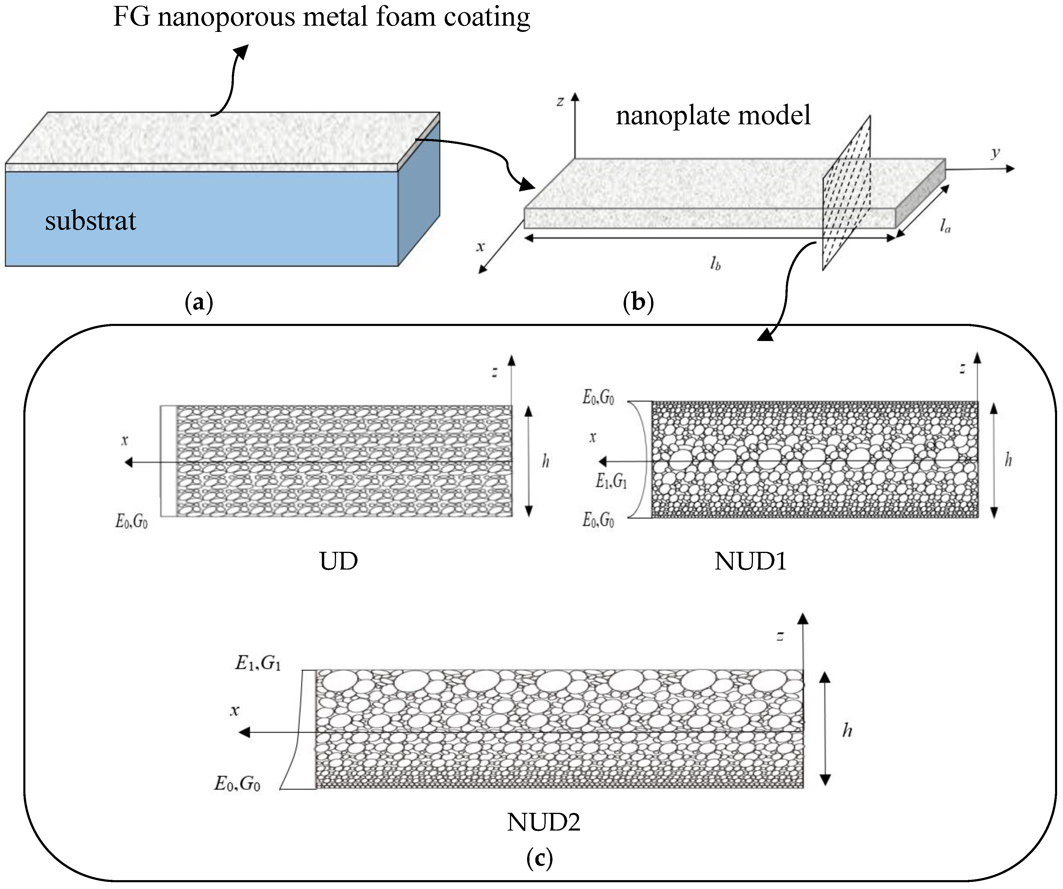
Article

Non-Local Buckling Analysis of Functionally Graded Nanoporous Metal Foam Nanoplates

1
Department of Mechanics, College of Sciences, Northeastern University, Shenyang 110819, China
2
Key Laboratory of Ministry of Education on Safe Mining of Deep Metal Mines, Northeastern University, Shenyang 110819, China
*
Author to whom correspondence should be addressed.
Coatings 2018, 8(11), 389; https://doi.org/10.3390/coatings8110389
Submission received: 30 September 2018 / Revised: 23 October 2018 / Accepted: 29 October 2018 / Published: 31 October 2018
(This article belongs to the Special Issue Functionally Graded Nanocomposite Surfaces)

Abstract

:
In this study, the buckling of functionally graded (FG) nanoporous metal foam nanoplates is investigated by combining the refined plate theory with the non-local elasticity theory. The refined plate theory takes into account transverse shear strains which vary quadratically through the thickness without considering the shear correction factor. Based on Eringen’s non-local differential constitutive relations, the equations of motion are derived from Hamilton’s principle. The analytical solutions for the buckling of FG nanoporous metal foam nanoplates are obtained via Navier’s method. Moreover, the effects of porosity distributions, porosity coefficient, small scale parameter, axial compression ratio, mode number, aspect ratio and length-to-thickness ratio on the buckling loads are discussed. In order to verify the validity of present analysis, the analytical results have been compared with other previous studies.

1. Introduction

Functionally graded materials (FGMs) are advanced composite materials whose compositions and volume fraction of materials vary gradually in one or more direction. Nanoporous metal foams, as a kind of high surface area-to-volume ratio group of materials, have become promising candidates for structural materials in various advanced technologies, such as high-efficiency heat-exchanger substrates, sensors and actuators [1,2]. Combining nanoporous metal foams with the FGM concept, the FG nanoporous metal foams are proposed. Due to their excellent fracture toughness and high electrical conductivities, FG nanoporous metal foam nanoplates are ideal for use as thin film elements. In the case of periodic wear and friction due to contact, nanoporous metal foam nanoplates can be applied to surface coatings to significantly increase the useful lifetimes of the required protective structures [3,4,5,6].
Nanostructures have attracted great attention in the scientific community due to their superior thermal, mechanical and electrical properties since Lijima [7] discovered carbon nanotubes. Different from their macroscopic counterparts, the size dependences of nanostructures are recognized to be more distinct due to the high ratio of surface area-to-volume. Therefore, a few size-dependent continuum mechanic models have been reported, such as the couple stress theory [8], the strain gradient theory [9] and the non-local elasticity theory [10,11]. Among these theories, the non-local elasticity theory was proposed by Eringen [10]. It can predict the behavior of nanostructures very easily and accurately with the consideration of the scale effect. This theory takes account of the scale effect by considering the stress at a reference point x to be a function of the strain field at every point x* of an elastic body. Many references employing the non-local elasticity theory for buckling and vibration analysis of nanobeams and nanoplates have been reported [12,13,14,15,16,17].
By assuming that the shear strains and stresses are constant across thickness, the first-order shear deformation theory (FSDT) takes into account the shear deformation effect and the shear correction factor. In 2006, a new theory accounting for shear deformations and involving two unknown functions was proposed by Shimpi and Patel [18,19]. This theory does not require a shear correction factor, and gives rise to transverse shear stress variation such that the transverse shear stresses vary parabolically across the thickness, satisfying shear stress free surface conditions. Moreover, the results obtained for plates with various thickness ratios using this theory are not only substantially more accurate than those obtained using the classical plate theory, but are almost comparable to those obtained using higher order theories having a greater number of unknown functions.
In the case of the growing maturation of nanomaterials, how to make novel nanomaterials play a role in practical applications is one of the challenges currently being faced. In micro- or nano-electromechanical system applications, many nanoplate structures can be found, such as nanosheet resonators and paddle-like resonators [20,21]. Therefore, the mechanical characteristics of nanoplates are of great interest to researchers. For example, Lu et al. [22] researched the bending and free vibration behaviors of a rectangular nanoplate based on the non-local Mindlin and Kirchhoff plate theories. The buckling problems of simply supported nanoplates were analyzed by Wang and Wang [23] considering both non-local elasticity and surface effects. Karimi et al. [24] investigated vibration, shear and biaxial buckling of rectangular nanoplates, by using the non-local two variable refined plate theory. Daneshmehr et al. [25] studied the free vibration problems of functionally graded nanoplates via non-local elasticity and high order theories. Based on the non-local elasticity theory, the buckling and vibration of multi-nanoplate systems were analyzed by Karlicic et al. [26]. Fatima et al. [27] presented free vibration analysis of nanoplates made of functionally graded materials by using a zeroth-order shear deformation theory. Liu et al. [28,29,30] developed an effective numerical model derived from Isogeometric analysis (IGA) for assessment of static bending, free vibration, and buckling behaviors of homogeneous and functionally graded microplates. Narendar [31] used the two-variable refined plate theory and non-local elasticity theory to analyze the buckling problems of isotropic nanoplates. Based on a non-local, four-variable refined plate theory, Belkorissat et al. [15] analyzed free vibration behavior of functionally graded nanoplates. Mechab et al. [32] examined the free vibration properties of porous functionally graded nanoplates resting on elastic foundations by using the two-variable refined plate theory. Based on the two-variable refined plate theory, Nami and Janghorban [33] investigated the free vibration problems of rectangular nanoplates via the strain gradient elasticity theory. Karimi and Shahidi [34] explored the effect of temperature change on the buckling, bending and vibration behaviors of orthotropic graphene sheets by considering small-scale and surface energy effects.
There have been few studies on the mechanical characteristics of FG nanoporous metal foam micro/nanobeams till now. Barati and Zenkour [35] examined the post-buckling behavior of nanoporous metal foam nanobeams based on a non-local, non-linear refined shear deformation beam model. By using the sinusoidal beam theory and modified strain gradient theory, Wang et al. [36] investigated bending and vibration of nanoporous metal foam microbeams.
In the current study, the buckling behavior of FG nanoporous metal foam nanoplates is investigated for the first time. Three types of porosity distribution, namely, uniform distribution (UD), non-uniform distribution 1 (NUD1) (symmetric), and non-uniform distribution 2 (NUD2) (asymmetric) are considered. The refined plate theory is employed and the non-local constitutive relations accounting for the small-scale effect are taken into account. To obtain analytical solutions of the present problem, Navier’s method is employed. Finally, the effects of several factors on the buckling of FG nanoporous metal foam nanoplates are presented in detail.

2. Theory and Formulation

2.1. FG Nanoporous Metal Foam Nanoplate

In the present study, an FG nanoporous metal foam coating is considered and modeled by a nanoplate with the length la, the width lb and the thickness h, as illustrated in Figure 1. We consider three different types of porosity distribution, namely, (1) uniform distribution (UD); (2) non-uniform distribution 1 (NUD1) (symmetric); and (3) non-uniform distribution 2 (NUD2) (asymmetric), as shown in Figure 1. It is clear that NUD1 and NUD2 exhibit graded characteristics like functionally graded materials [37,38,39,40,41].
In the case of UD, the elasticity modulus E and shear modulus G are constant along the thickness of the nanoplate. In the case of NUD1, the values of the elasticity modulus and shear modulus on the top and bottom surfaces are the maxima, while the values are the minima at the mid-plane of the nanoplate due to the largest porosity size. In the case of NUD 2, the elasticity modulus and shear modulus vary gradually from the top surface to the bottom surface; the maximum values occur at the bottom surface while the minimum values occur at the top surface. For these three types of porosity distribution, the elasticity modulus E and shear modulus G are defined as [42]:
UD:
E ( z ) = E 0 ( 1 λ η )
G ( z ) = G 0 ( 1 λ η )
NUD1:
E ( z ) = E 0 [ 1 λ cos ( π z h ) ]
G ( z ) = G 0 [ 1 λ cos ( π z h ) ]
NUD2:
E ( z ) = E 0 [ 1 λ cos ( π z 2 h + π 4 ) ]
G ( z ) = G 0 [ 1 λ cos ( π z 2 h + π 4 ) ]
where E0 and G0 are the maximum values of elasticity modulus and shear modulus, respectively; λ is the porosity coefficient determined as [42]:
λ = 1 E 1 E 0 = 1 G 1 G 0
where E1 and G1 are the minimum values of elasticity modulus and shear modulus, respectively.
The coefficient η in UD is dependent on λ, and can be expressed as [42]:
η = 1 λ 1 λ ( 2 π 1 λ 2 π + 1 ) 2

2.2. The Non-Local Elasticity Theory

According to Eringen’s non-local elasticity theory [11], the stress state at a reference point x in an elastic body depends not only on strains at x but also on the strains at all other points x* of the body. The stress tensor of a non-local elastic body can be written as [11]:
σ = V α ( | x * x | , τ ) t ( x * ) d x *
where α(|x* − x|, τ) is the non-local modulus and τ is the material constant (τ = e0a/l), e0 is a material constant, a is the internal characteristic length (such as the C–C bond length and granular size) and l is the external characteristic length (e.g., graphene sheet length and crack length); t(x*) is the local stress tensor at any point x* in the body. The stress t at a point x in an elastic body is related to the strain ε as follows:
t ( x ) = C ( x ) : ε ( x )
where “:” and C are a “double-dot product” and the fourth-order elasticity tensor, respectively. To avoid solving the integral constitutive equation, the constitutive relations of the non-local elasticity model can be expressed as:
( 1 g 2 2 ) σ = t
where 2 is the Laplacian operator, and g = e0a is the non-local small scale parameter.

2.3. Governing Equations of Motion

The basic assumptions of the refined plate theory are as follows:
  • The displacements u (in the x direction), v (in the y direction) and w (in the z direction) are small compared to the thickness h of the nanoplate. Hence, the strains involved are infinitesimal. By considering the strain-displacement relations, the shear strains γxy, γzx, γyz and normal strains εxx, εyy, εzz can be written as:
    ε x x = u x ,   ε y y = v y ,   ε z z = w z , γ x y = v x + u y ,   γ z x = u z + w x ,   γ y z = v z + w y
  • The transverse displacement w includes two components: the bending component wB and the shear component wS. Both of them are functions of x, y, and t (time) [31,43,44]:
    w ( x , y , t ) = w B ( x , y , t ) + w S ( x , y , t )
  • Compared with in-plane stresses σxx and σyy, the transverse normal stress σzz can be negligible.
  • The displacement components u and v include extension, bending and shear components:
    u = u 0 + u B + u S v = v 0 + v B + v S
The bending components uB and vB and shear components uS and vS are defined as [31,43]:
u B = z w B x v B = z w B y
u S = z [ 1 4 5 3 ( z h ) 2 ] w S x v S = z [ 1 4 5 3 ( z h ) 2 ] w S y
Using Equations (12)–(16), the displacement field can be written as:
u ( x , y , z , t ) = u 0 ( x , y , t ) z w B x + z [ 1 4 5 3 ( z h ) 2 ] w S x v ( x , y , z , t ) = v 0 ( x , y , t ) z w B y + z [ 1 4 5 3 ( z h ) 2 ] w S y w ( x , y , z , t ) = w B ( x , y , t ) + w S ( x , y , t )
Considering the transverse shear strains vary parabolically through the thickness of the nanoplate the shear correction factors are not therefore required. The kinematic relations can be obtained as follows:
{ ε x x ε y y γ x y } = { ε x x 0 ε y y 0 γ x y 0 } + z { ε x x B ε y y B γ x y B } + f { ε x x S ε y y S γ x y S } { γ y z γ z x } = φ { γ y z S γ z x S }
where
{ ε x x 0 ε y y 0 γ x y 0 } = { u 0 / x v 0 / y u 0 / y + v 0 / x } , { ε x x B ε y y B γ x y B } = { 2 w B / x 2 2 w B / y 2 2 2 w B / x y } , { ε x x S ε y y S γ x y S } = { 2 w S / x 2 2 w S / y 2 2 2 w S / x y } , { γ y z S γ z x S } = { w S / y w S / x } , { f = 1 4 z + 5 3 z ( z h ) 2 φ = 5 4 5 ( z h ) 2
The strain-displacement relations can be obtained using Equations (18) and (19) as:
{ ε x x = u 0 x z 2 w B x 2 + [ 1 4 z 5 3 z ( z h ) 2 ] 2 w S x 2 ε y y = v 0 y z 2 w B y 2 + [ 1 4 z 5 3 z ( z h ) 2 ] 2 w S y 2 ε z z = 0 γ x y = u 0 y + v 0 x 2 z 2 w B x y + 2 [ 1 4 z 5 3 z ( z h ) 2 ] 2 w S x y γ y z = [ 5 4 5 ( z h ) 2 ] w S y γ z x = [ 5 4 5 ( z h ) 2 ] w S x
For the FG nanoporous metal foam nanoplate, the non-local constitutive relationship can be expressed as:
{ σ x x σ y y τ x y τ y z τ z x } g 2 ( 2 x 2 + 2 y 2 ) { σ x x σ y y τ x y τ y z τ z x } = [ K 11 K 12 0 0 0 K 12 K 22 0 0 0 0 0 K 66 0 0 0 0 0 K 55 0 0 0 0 0 K 44 ] { ε x x ε y y γ x y γ y z γ z x }
where the elastic constants Kij are:
K 11 = K 22 = E ( z ) 1 ν 2 K 12 = ν E ( z ) 1 ν 2 K 44 = K 55 = K 66 = G ( z ) = E ( z ) 2 ( 1 + ν )
where E(z), G(z), ν are the elasticity modulus, shear modulus and Poisson’s ratio, respectively.
The strain energy U of the FG nanoporous metal foam nanoplate can be expressed as:
U = 1 2 V ( σ x x ε x x + σ y y ε y y + τ x y γ x y + τ y z γ y z + τ x z γ x z ) d V
Substituting Equation (20) into Equation (23) and integrating through the thickness of the nanoplate, the strain energy of the FG nanoporous metal foam nanoplate can be written as:
U = 1 2 A ( N x x u 0 x + N y y v 0 y + N x y [ u 0 y + v 0 x ] M x x B 2 w B x 2 M y y B 2 w B y 2 2 M x y B 2 w B x y ) d x d y + 1 2 A ( Q y z w S y + Q z x w S x M x x S 2 w S x 2 M y y S 2 w S y 2 2 M x y S 2 w S x y ) d x d y
where N, M and Q are the resultant forces, moments and shear forces, respectively. They are defined by:
{ N x x = h 2 h 2 σ x x d z N y y = h 2 h 2 σ y y d z N x y = h 2 h 2 τ x y d z
{ M x x B = h 2 h 2 σ x x z d z M y y B = h 2 h 2 σ y y z d z M x y B = h 2 h 2 τ x y z d z
{ M x x S = h 2 h 2 σ x x [ 1 4 z + 5 3 z ( z h ) 2 ] d z M y y S = h 2 h 2 σ y y [ 1 4 z + 5 3 z ( z h ) 2 ] d z M x y S = h 2 h 2 τ x y [ 1 4 z + 5 3 z ( z h ) 2 ] d z
{ Q z x = h 2 h 2 φ τ z x d z Q y z = h 2 h 2 φ τ y z d z
By substituting Equations (19)–(21) into Equations (25)–(28), the stress resultants can be written as:
  { N x x N y y N x y } g 2 ( 2 x 2 + 2 y 2 ) { N x x N y y N x y } = [ A 11 A 12 0 A 12 A 22 0 0 0 A 66 ] { ε x x 0 ε y y 0 γ x y 0 } + [ B 11 B 12 0 B 12 B 22 0 0 0 B 66 ] { ε x x B ε y y B γ x y B } + [ B 11 S B 12 S 0 B 12 S B 22 S 0 0 0 B 66 S ] { ε x x S ε y y S γ x y S }
  { M x x B M y y B M x y B } g 2 ( 2 x 2 + 2 y 2 ) { M x x B M y y B M x y B } = [ B 11 B 12 0 B 12 B 22 0 0 0 B 66 ] { ε x x 0 ε y y 0 γ x y 0 } + [ D 11 D 12 0 D 12 D 22 0 0 0 D 66 ] { ε x x B ε y y B γ x y B } + [ D 11 S D 12 S 0 D 12 S D 22 S 0 0 0 D 66 S ] { ε x x S ε y y S γ x y S }
{ M x x S M y y S M x y S } g 2 ( 2 x 2 + 2 y 2 ) { M x x S M y y S M x y S } = [ B 11 S B 12 S 0 B 12 S B 22 S 0 0 0 B 66 S ] { ε x x 0 ε y y 0 γ x y 0 } + [ D 11 S D 12 S 0 D 12 S D 22 S 0 0 0 D 66 S ] { ε x x B ε y y B γ x y B } + [ H 11 S H 12 S 0 H 12 S H 22 S 0 0 0 H 66 S ] { ε x x S ε y y S γ x y S }
{ Q y z Q z x } g 2 ( 2 x 2 + 2 y 2 ) { Q y z Q z x } = [ K 55 S 0 0 K 44 S ] { γ y z S γ z x S }
where
{ A 11 B 11 B 11 S D 11 D 11 S H 11 S A 12 B 12 B 12 S D 12 D 12 S H 12 S A 22 B 22 B 22 S D 22 D 22 S H 22 S A 66 B 66 B 66 S D 66 D 66 S H 66 S } = h 2 h 2 { K 11 K 12 K 22 K 66 } ( 1 , z , f ( z ) , z 2 , z f ( z ) , f ( z ) 2 ) d z { K 44 S K 55 S } = h 2 h 2 { K 44 K 55 } φ ( z ) 2 d z
It should be noted that the stress resultants in Equations (29)–(32) can be reduced to classical relations when the small-scale parameter g is set to zero.
The work done by the applied forces can be written as:
V = 1 2 A [ N x x 0 ( ( w B + w S ) x ) 2 + N y y 0 ( ( w B + w S ) y ) 2 + 2 N x y 0 ( w B + w S ) x ( w B + w S ) y ] d x d y
where N x x 0 , N y y 0 and N x y 0 are the in-plane distributed forces.
Then, Hamilton’s principle is used to derive the equations of motion, which can be expressed in the form of
0 t ( δ U + δ V ) d t = 0
where δ indicates a variation with respect to x and y.
Substituting Equations (24) and (34) into Equation (35), the governing equations of the FG nanoporous metal foam nanoplate can be obtained as:
δ u 0 : N x x x + N x y y = 0
δ v 0 : N x y x + N y y y = 0
δ w B : 2 M x x B x 2 + 2 2 M x y B x y + 2 M y y B y 2 + N x x 0 2 ( w B + w S ) x 2 + 2 N x y 0 2 ( w B + w S ) x y + N y y 0 2 ( w B + w S ) y 2 = 0
δ w S : 2 M x x S x 2 + 2 2 M x y S x y + 2 M y y S y 2 + Q x z x + Q y z y + N x x 0 2 ( w B + w S ) x 2 + 2 N x y 0 2 ( w B + w S ) x y + N y y 0 2 ( w B + w S ) y 2 = 0
For the present buckling study, the in-plane distributed forces can be written as:
N x x 0 = N 0 , N x y 0 = 0 , N y y 0 = ζ N 0
where ζ is the compression ratio.
Using Equations (29)–(32), (38) and (39), the governing equations for buckling of the FG nanoporous metal foam nanoplate can be obtained in terms of wB and wS:
B 11 3 u x 3 + ( B 12 + 2 B 66 ) 3 u x y 2 + ( B 12 + 2 B 66 ) 3 v x 2 y + B 22 3 v y 3 D 11 4 w B x 4 2 ( D 12 + 2 D 66 ) 4 w B x 2 y 2 D 22 4 w B y 4 D 11 S 4 w S x 4 2 ( D 12 S + 2 D 66 S ) 4 w S x 2 y 2 D 22 S 4 w S y 4 + N 0 ( 2 w B x 2 + ζ 2 w B y 2 + 2 w S x 2 + ζ 2 w S y 2 ) N 0 g 2 ( 4 w B x 4 + ( 1 + ζ ) 4 w B x 2 y 2 + ζ 4 w B y 4 + 4 w S x 4 + ( 1 + ζ ) 4 w S x 2 y 2 + ζ 4 w S y 4 ) = 0
B 11 S 3 u x 3 + ( B 12 S + 2 B 66 S ) 3 u x y 2 + ( B 12 S + 2 B 66 S ) 3 v x 2 y + B 22 S 3 v y 3 D 11 S 4 w B x 4 2 ( D 12 S + 2 D 66 S ) 4 w B x 2 y 2 D 22 S 4 w B y 4 H 11 S 4 w S x 4 2 ( H 12 S + 2 H 66 S ) 4 w S x 2 y 2 H 22 S 4 w S y 4 + K 44 S 2 w S x 2 + K 55 S 2 w S y 2 + N 0 ( 2 w B x 2 + ζ 2 w B y 2 + 2 w S x 2 + ζ 2 w S y 2 ) N 0 g 2 ( 4 w B x 4 + ( 1 + ζ ) 4 w B x 2 y 2 + ζ 4 w B y 4 + 4 w S x 4 + ( 1 + ζ ) 4 w S x 2 y 2 + ζ 4 w S y 4 ) = 0
In the present study, the full simply supported boundary condition is considered and it is given as follows:
w ( x , 0 ) = w ( x , l b ) = w ( 0 , y ) = w ( l a , y ) = 0 M x x ( 0 , y ) = M x x ( l a , y ) = M y y ( x , 0 ) = M y y ( x , l b ) = 0
The following solutions for wB and wS are chosen to satisfy the boundary condition in Equation (43):
w B = m = 1 n = 1 U 3 ( m n ) B sin ( α x ) sin ( β y )
w S = m = 1 n = 1 U 3 ( m n ) S sin ( α x ) sin ( β y )
where m and n are the mode numbers, α = mπ/la and β = nπ/lb.
Substituting Equations (44) and (45) into Equations (41) and (42), the following matrix form can be obtained:
[ Z 11 Z 12 Z 21 Z 22 ] { U 3 ( m n ) B U 3 ( m n ) S } = { 0 0 }
where
Z 11 = ( D 11 α 4 + 2 ( D 12 + 2 D 66 ) α 2 β 2 + D 22 β 4 ) N 0 ( α 2 + ζ β 2 ) N 0 g 2 ( α 4 + ( 1 + ζ ) α 2 β 2 + ζ β 4 )
Z 12 = Z 21 = ( D 11 S α 4 + 2 ( D 12 S + 2 D 66 S ) α 2 β 2 + D 22 S β 4 ) N 0 ( α 2 + ζ β 2 ) N 0 g 2 ( α 4 + ( 1 + ζ ) α 2 β 2 + ζ β 4 )
Z 22 = ( H 11 S α 4 + 2 ( H 12 S + 2 H 66 S ) α 2 β 2 + H 22 S β 4 ) ( K 44 S α 2 + K 55 S β 2 ) N 0 ( α 2 + ζ β 2 ) N 0 g 2 ( α 4 + ( 1 + ζ ) α 2 β 2 + ζ β 4 )
By setting the determinant of the coefficient matrix of Equation (46) equal to zero, the buckling load N0 is obtained. The critical buckling load is the minimum value of N0 (m, n), where m = 1, n = 1. For convenience, the non-dimensional buckling load is defined as:
N ¯ 0 = N 0 × l a 2 D 110
where
D 110 = E 0 h 3 12 ( 1 ν 2 )

3. Results and Discussion

In order to demonstrate the accuracy of the present method, firstly, a comparison study was conducted for a homogeneous nanoplate. The present results were compared with the available data reported in the literature [31], as shown in Figure 2 and Figure 3. A very good agreement was reached between these figures, showing the validity of the present analysis.
In the following, the FG nanoporous metal foam nanoplate shown in Figure 1 was considered. It had the following material properties: E0 = 200 Gpa, G0 = 76.92 Gpa and ν = 1/3.
The variation of non-dimensional buckling load with a mode number n of FG nanoporous metal foam nanoplate is shown in Figure 4 for different small-scale parameters. It could be observed that the non-dimensional buckling load increased with an increasing mode number n. In addition, the non-dimensional buckling load decreased with the increase of the small-scale parameter. The classical theory (g = 0) resulted in the highest buckling load. It was also seen that when the mode number n was small, there was no significant difference among non-dimensional buckling loads for different small-scale parameters. However, as mode number n increased, the nonlocal effect became more and more notable.
Figure 5 shows the effect of porosity distribution on the non-dimensional critical buckling load, where h = 5 nm, m = n = 1, ζ = 1 and λ = 0.5. In the current analysis, two cases of square and rectangular nanoplates were considered. It could be seen that non-dimensional critical buckling load was the smallest in the case of UD, regardless of whether it was a square or a rectangular nanoplate. Therefore, the UD nanoplate was the most unstable. It could be found that the NUD1 nanoplate had the largest non-dimensional critical buckling load, showing this type of nanoplate was the most stable.
Figure 6 presented the influence of porosity coefficient λ on the non-dimensional critical buckling load of the FG nanoporous nanoplate. It was found that there was a remarkable decreasing trend for the non-dimensional critical buckling load when the porosity coefficient increased. The reason for this behavior was that the stiffness of nanoplates decreased with the porosity coefficient.
In Figure 7, the non-dimensional critical buckling load versus the length-to-thickness ratio of the square FG nanoporous nanoplate is shown. It was seen that the non-dimensional critical buckling load increased with the rise of length-to-thickness ratio for all types of porosity distribution. It was also found that the influence of small-scale parameter on the non-dimensional critical buckling load weakened with the rise of the length-to-thickness ratio.
In Figure 8, the non-dimensional critical buckling load versus the axial compression ratio ζ is shown. Here, ζ > 0 corresponds to the biaxial compressive loads and ζ = 0 means a uniaxial load. Figure 8 shows that the non-dimensional critical buckling load became smaller and smaller as the axial compression ratio increased.
Figure 9 shows the variation of the non-dimensional buckling load with a mode number m of the FG nanoporous nanoplate. It could be seen that the larger mode number m led to the higher non-dimensional buckling load. Additionally, the difference between the non-dimensional buckling loads with n = 1 and n = 2 got smaller and smaller as the mode number m increased.
Table 1 and Table 2 show the non-dimensional buckling loads of square and rectangular FG nanoporous nanoplates under different conditions, respectively. It could be seen that the FG nanoporous nanoplate had a lower non-dimensional buckling load than its solid counterpart. Additionally, the larger mode number resulted in the larger non-dimensional buckling load.
In Table 3, the effect of surface area on the non-dimensional critical buckling load of the FG nanoporous nanoplate is discussed. When the thickness of the nanoplate was fixed, it could be found that the non-dimensional critical buckling load increased with the rise of surface area. It should be noticed that the real buckling load decreased with the surface area because the stiffness of the nanoplate decreased. The contrary tendency was due to the dimensionless formulation introduced in Equation (50).
The effect of nanoplate thickness on the non-dimensional critical buckling load of square and rectangular nanoplates is shown in Table 4 and Table 5, respectively. With the increase of the nanoplate thickness, the variation of the non-dimensional critical buckling load showed a decreasing trend for both square and rectangular nanoplates. In Table 6, the influence of aspect ratio on the non-dimensional critical buckling load is studied in the condition that the FG nanoporous nanoplate is subjected to the biaxial symmetrical loads (ζ = 1). It could be seen that the non-dimensional critical buckling load decreased as the aspect ratio increased.

4. Conclusions

In this study, the buckling behavior of FG nanoporous metal foam nanoplates was investigated based on the non-local elasticity theory and the refined plate theory. Hamilton’s principle was used to derive the governing equations of the system. Analytical solutions to the buckling problem were obtained via Navier’s method. The following conclusions were obtained:
  • An FG nanoporous metal foam nanoplate had a smaller critical buckling load than its solid counterpart. Among the three types of porosity distribution, the NUD1 nanoplate had the largest buckling load and the ND nanoplate had the smallest buckling load.
  • The critical buckling load of FG nanoporous metal foam nanoplates decreased with the rise of the porosity coefficient and the small-scale parameter.
  • The critical buckling load decreased as the aspect ratio increased. Additionally, the FG nanoporous metal foam nanoplate was more stable when the surface area got smaller.
  • The buckling load increased as the mode numbers rose; in addition, the scale effect was quite significant on the buckling load at large mode number n.

Author Contributions

Conceptualization, Y.W.; Methodology, Y.W. and Z.Z.; Software, Z.Z.; Validation, Z.Z.; Formal Analysis, Z.Z.; Investigation, Z.Z.; Resources, Y.W.; Data Curation, Z.Z.; Writing-Original Draft Preparation, Y.W. and Z.Z.; Writing-Review & Editing, Y.W.; Visualization, Z.Z.; Supervision, Y.W.; Project Administration, Y.W.; Funding Acquisition, Y.W.

Funding

This research was supported by the National Natural Science Foundation of China (Grant no. 11672071) and the Fundamental Research Funds for the Central Universities (Grant no. N170504023).

Conflicts of Interest

The authors declare no conflict of interest.

References

  1. Biener, J.; Wittstock, A.; Zepeda-Ruiz, L.A.; Biener, M.M.; Zielasek, V.; Kramer, D.; Viswanath, R.N.; Weissmüller, J.; Bäumer, M.; Hamza, A.V. Surface-chemistry-driven actuation in nanoporous gold. Nat. Mater. 2009, 8, 47–51. [Google Scholar] [CrossRef] [PubMed]
  2. Park, H.; Ahn, C.; Jo, H.; Choi, M.; Kim, D.S.; Kim, D.K.; Jeon, S.; Choe, H. Large-area metal foams with highly ordered sub-micrometer-scale pores for potential applications in energy areas. Mater. Lett. 2014, 129, 174–177. [Google Scholar] [CrossRef]
  3. Freund, L.B.; Suresh, S. Thin Film Materials: Stress, Defect Formation and Surface Evolution, 1st ed.; Cambridge University Press: Cambridge, UK, 2003. [Google Scholar]
  4. Rongong, J.A.; Goruppa, A.A.; Buravalla, V.R.; Tomlinson, G.R.; Jones, F.R. Plasma deposition of constrained layer damping coatings. Proc. Inst. Mech. Eng. Part C J. Mech. Eng. Sci. 2004, 218, 669–680. [Google Scholar] [CrossRef] [Green Version]
  5. Yu, L.; Ma, Y.; Zhou, C.; Xu, H. Damping efficiency of the coating structure. Int. J. Solids Struct. 2005, 42, 3045–3058. [Google Scholar] [CrossRef]
  6. Catania, G.; Strozzi, M. Damping oriented design of thin-walled mechanical components by means of multi-layer coating technology. Coatings 2018, 8, 73. [Google Scholar] [CrossRef]
  7. Iijima, S. Helical microtubules of graphitic carbon. Nature 1991, 354, 56. [Google Scholar] [CrossRef]
  8. Hadjesfandiari, A.R.; Dargush, G.F. Couple stress theory for solids. Int. J. Solids Struct. 2011, 48, 2496–2510. [Google Scholar] [CrossRef]
  9. Nix, W.D.; Gao, H.J. Indentation size effects in crystalline materials: A law for strain gradient plasticity. J. Mech. Phys. Solids 1998, 46, 411–425. [Google Scholar] [CrossRef]
  10. Eringen, A.C. Nonlocal polar elastic continua. Int. J. Eng. Sci. 1972, 10, 1–16. [Google Scholar] [CrossRef]
  11. Eringen, A.C. On differential equations of nonlocal elasticity and solutions of screw dislocation and surface waves. J. Appl. Phys. 1983, 54, 4703–4710. [Google Scholar] [CrossRef]
  12. Lambin, P. Elastic properties and stability of physisorbed graphene. Appl. Sci. 2014, 4, 282–304. [Google Scholar] [CrossRef]
  13. Farajpour, A.; Shahidi, A.R.; Mohammadi, M.; Mahzoon, M. Buckling of orthotropic micro/nanoscale plates under linearly varying in-plane load via nonlocal continuum mechanics. Compos. Struct. 2012, 94, 1605–1615. [Google Scholar] [CrossRef]
  14. Aksencer, T.; Aydogdu, M. Levy type solution method for vibration and buckling of nanoplates using nonlocal elasticity theory. Physica E 2011, 43, 954–959. [Google Scholar] [CrossRef]
  15. Belkorissat, I.; Houari, M.S.A.; Tounsi, A.; Bedia, E.A.A.; Mahmoud, S.R. On vibration properties of functionally graded nano-plate using a new nonlocal refined four variable model. Steel Compos. Struct. 2015, 18, 1063–1081. [Google Scholar] [CrossRef]
  16. Ke, L.L.; Wang, Y.S.; Yang, J.; Kitipornchai, S. Free vibration of size-dependent magneto-electro-elastic nanoplates based on the nonlocal theory. Acta Mech. Sin. 2014, 30, 516–525. [Google Scholar] [CrossRef]
  17. Ke, L.L.; Wang, Y.S.; Wang, Z.D. Nonlinear vibration of the piezoelectric nanobeams based on the nonlocal theory. Compos. Struct. 2012, 94, 2038–2047. [Google Scholar] [CrossRef]
  18. Shimpi, R.P.; Patel, H.G. A two variable refined plate theory for orthotropic plate analysis. Int. J. Solids Struct. 2006, 43, 6783–6799. [Google Scholar] [CrossRef]
  19. Shimpi, R.P.; Patel, H.G. Free vibrations of plate using two variable refined plate theory. J. Sound Vib. 2006, 296, 979–999. [Google Scholar] [CrossRef]
  20. Evoy, S.; Carr, D.W.; Sekaric, L.; Olkhovets, A.; Parpia, J.M.; Craighead, H.G. Nanofabrication and electrostatic operation of single-crystal silicon paddle oscillators. J. Appl. Phys. 1999, 86, 6072–6077. [Google Scholar] [CrossRef]
  21. Bunch, J.S.; Van Der Zande, A.M.; Verbridge, S.S.; Frank, I.W.; Tanenbaum, D.M.; Parpia, J.M.; Craighead, H.G.; McEuen, P.L. Electromechanical resonators from graphene sheets. Science 2007, 315, 490–493. [Google Scholar] [CrossRef] [PubMed]
  22. Lu, P.; Zhang, P.Q.; Lee, H.P.; Wang, C.M.; Reddy, J.N. Non-local elastic plate theories. Proc. R. Soc. Lond. Ser. A 2007, 463, 3225–3240. [Google Scholar] [CrossRef] [Green Version]
  23. Wang, K.F.; Wang, B.L. Combining effects of surface energy and non-local elasticity on the buckling of nanoplates. Micro Nano Lett. 2011, 6, 941–943. [Google Scholar] [CrossRef]
  24. Karimi, M.; Haddad, H.A.; Shahidi, A.R. Combining surface effects and non-local two variable refined plate theories on the shear/biaxial buckling and vibration of silver nanoplates. Micro Nano Lett. 2015, 10, 276–281. [Google Scholar] [CrossRef]
  25. Daneshmehr, A.; Rajabpoor, A.; Hadi, A. Size dependent free vibration analysis of nanoplates made of functionally graded materials based on nonlocal elasticity theory with high order theories. Int. J. Eng. Sci. 2015, 95, 23–35. [Google Scholar] [CrossRef]
  26. Karličić, D.; Adhikari, S.; Murmu, T.; Cajić, M. Exact closed-form solution for non-local vibration and biaxial buckling of bonded multi-nanoplate system. Compos. Part B Eng. 2014, 66, 328–339. [Google Scholar] [CrossRef]
  27. Bounouara, F.; Benrahou, K.H.; Belkorissat, I.; Tounsi, A. A nonlocal zeroth-order shear deformation theory for free vibration of functionally graded nanoscale plates resting on elastic foundation. Steel Compos. Struct. 2016, 20, 227–249. [Google Scholar] [CrossRef]
  28. Liu, S.; Yu, T.; Bui, T.Q. Size effects of functionally graded moderately thick microplates: A novel non-classical simple-FSDT isogeometric analysis. Eur. J. Mech. A. Solids 2017, 66, 446–458. [Google Scholar] [CrossRef]
  29. Liu, S.; Yu, T.; Bui, T.Q.; Xia, S. Size-dependent analysis of homogeneous and functionally graded microplates using IGA and a non-classical Kirchhoff plate theory. Compos. Struct. 2017, 172, 34–44. [Google Scholar] [CrossRef]
  30. Liu, S.; Yu, T.; Van Lich, L.; Yin, S.; Bui, T.Q. Size effect on cracked functional composite micro-plates by an XIGA-based effective approach. Meccanica 2018, 53, 2637–2658. [Google Scholar] [CrossRef]
  31. Narendar, S. Buckling analysis of micro-/nano-scale plates based on two-variable refined plate theory incorporating nonlocal scale effects. Compos. Struct. 2011, 93, 3093–3103. [Google Scholar] [CrossRef]
  32. Mechab, I.; Mechab, B.; Benaissa, S.; Serier, B.; Bouiadjra, B.B. Free vibration analysis of FGM nanoplate with porosities resting on Winkler Pasternak elastic foundations based on two-variable refined plate theories. J. Braz. Soc. Mech. Sci. Eng. 2016, 38, 2193–2211. [Google Scholar] [CrossRef]
  33. Nami, M.R.; Janghorban, M. Free vibration analysis of rectangular nanoplates based on two-variable refined plate theory using a new strain gradient elasticity theory. J. Braz. Soc. Mech. Sci. Eng. 2015, 37, 313–324. [Google Scholar] [CrossRef]
  34. Karimi, M.; Shahidi, A.R. Thermo-mechanical vibration, buckling, and bending of orthotropic graphene sheets based on nonlocal two-variable refined plate theory using finite difference method considering surface energy effects. Proc. Inst. Mech. Eng. Part N J. Nanomater. Nanoeng. Nanosyst. 2017, 231, 111–130. [Google Scholar] [CrossRef]
  35. Barati, M.R.; Zenkour, A.M. Investigating post-buckling of geometrically imperfect metal foam nanobeams with symmetric and asymmetric porosity distributions. Compos. Struct. 2017, 182, 91–98. [Google Scholar] [CrossRef]
  36. Wang, Y.Q.; Zhao, H.L.; Ye, C.; Zu, J.W. A porous microbeam model for bending and vibration analysis based on the sinusoidal beam theory and modified strain gradient theory. Int. J. Appl. Mech. 2018, 10, 1850059. [Google Scholar] [CrossRef]
  37. Wang, Y.Q.; Zu, J.W. Nonlinear dynamics of a translational FGM plate with strong mode interaction. Int. J. Struct. Stab. Dyn. 2018, 18, 1850031. [Google Scholar] [CrossRef]
  38. Wang, Y.Q.; Zu, J.W. Nonlinear steady-state responses of longitudinally traveling functionally graded material plates in contact with liquid. Compos. Struct. 2017, 164, 130–144. [Google Scholar] [CrossRef]
  39. Wang, Y.Q. Electro-mechanical vibration analysis of functionally graded piezoelectric porous plates in the translation state. Acta Astronaut. 2018, 143, 263–271. [Google Scholar] [CrossRef]
  40. Wang, Y.Q.; Zu, J.W. Vibration behaviors of functionally graded rectangular plates with porosities and moving in thermal environment. Aerosp. Sci. Technol. 2017, 69, 550–562. [Google Scholar] [CrossRef]
  41. Wang, Y.Q.; Ye, C.; Zu, J.W. Identifying the temperature effect on the vibrations of functionally graded cylindrical shells with porosities. Appl. Math. Mech. 2018, 1–18. [Google Scholar] [CrossRef]
  42. Chen, D.; Kitipornchai, S.; Yang, J. Nonlinear free vibration of shear deformable sandwich beam with a functionally graded porous core. Thin-Walled Struct. 2016, 107, 39–48. [Google Scholar] [CrossRef]
  43. Malekzadeh, P.; Shojaee, M. Free vibration of nanoplates based on a nonlocal two-variable refined plate theory. Compos. Struct. 2013, 95, 443–452. [Google Scholar] [CrossRef]
  44. Narendar, S.; Gopalakrishnan, S. Scale effects on buckling analysis of orthotropic nanoplates based on nonlocal two-variable refined plate theory. Acta Mech. 2012, 223, 395–413. [Google Scholar] [CrossRef]
Figure 1. Functionally graded (FG) nanoporous metal foam nanoplate and three types of porosity distribution, namely (1) uniform distribution (UD), (2) non-uniform distribution 1 (NUD1) (symmetric), and (3) non-uniform distribution 2 (NUD2) with (a) coating on substrate, (b) nanoplate model, (c) cross section.
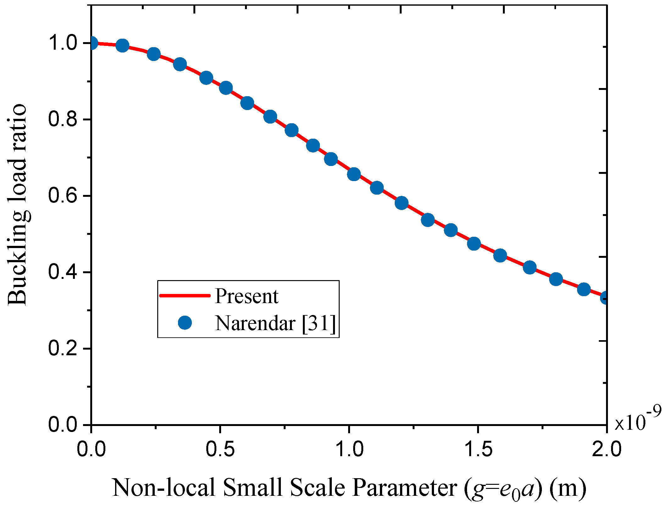
Coatings 08 00389 g001
Figure 2. Variation of buckling load ratio with a non-local small-scale parameter for a rectangular homogeneous nanoplate (m = n = 1, a = 10 nm, b = 5 nm).
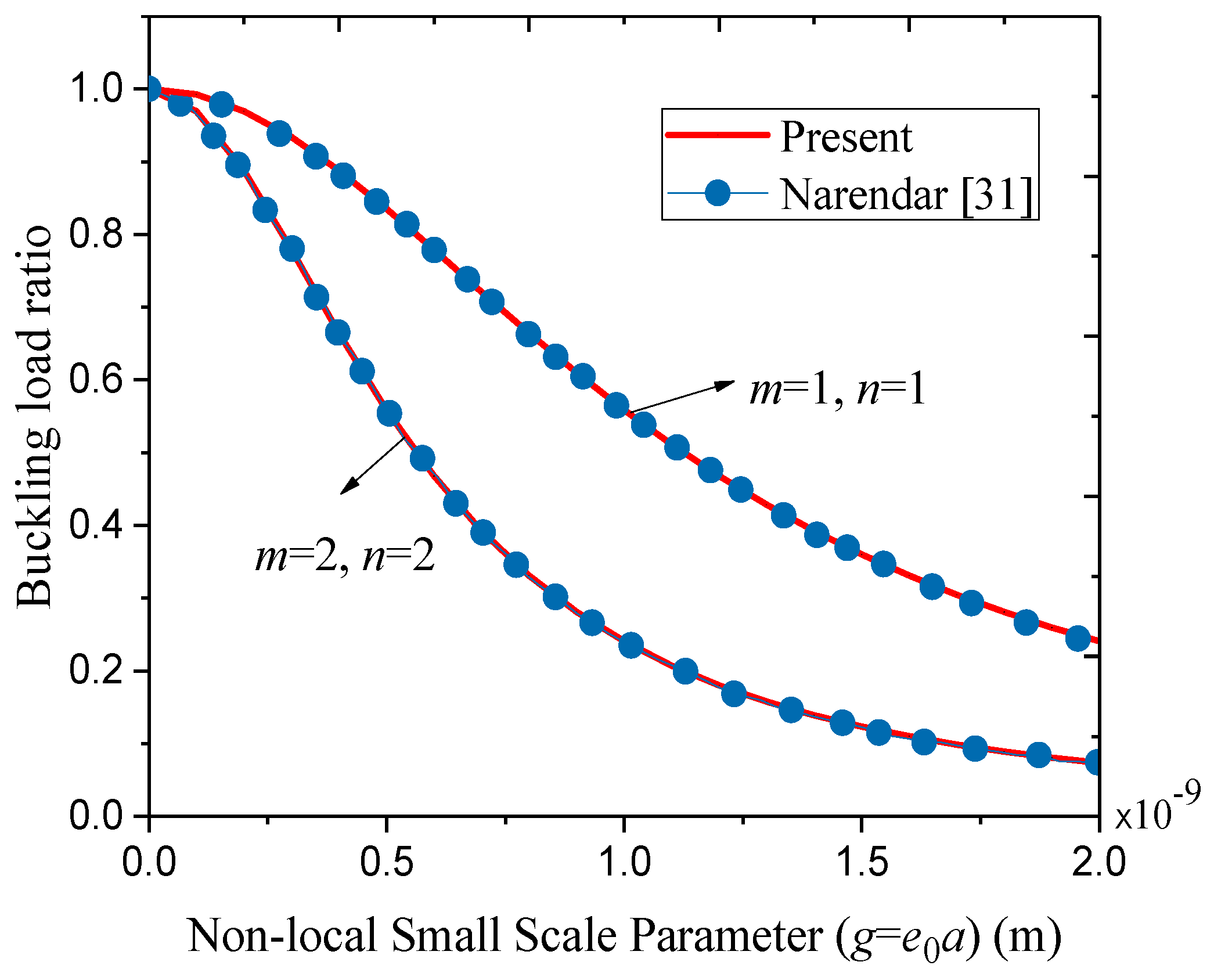
Coatings 08 00389 g002
Figure 3. Variation of buckling load ratio with a non-local small-scale parameter for a square homogeneous nanoplate (a = b = 5 nm).
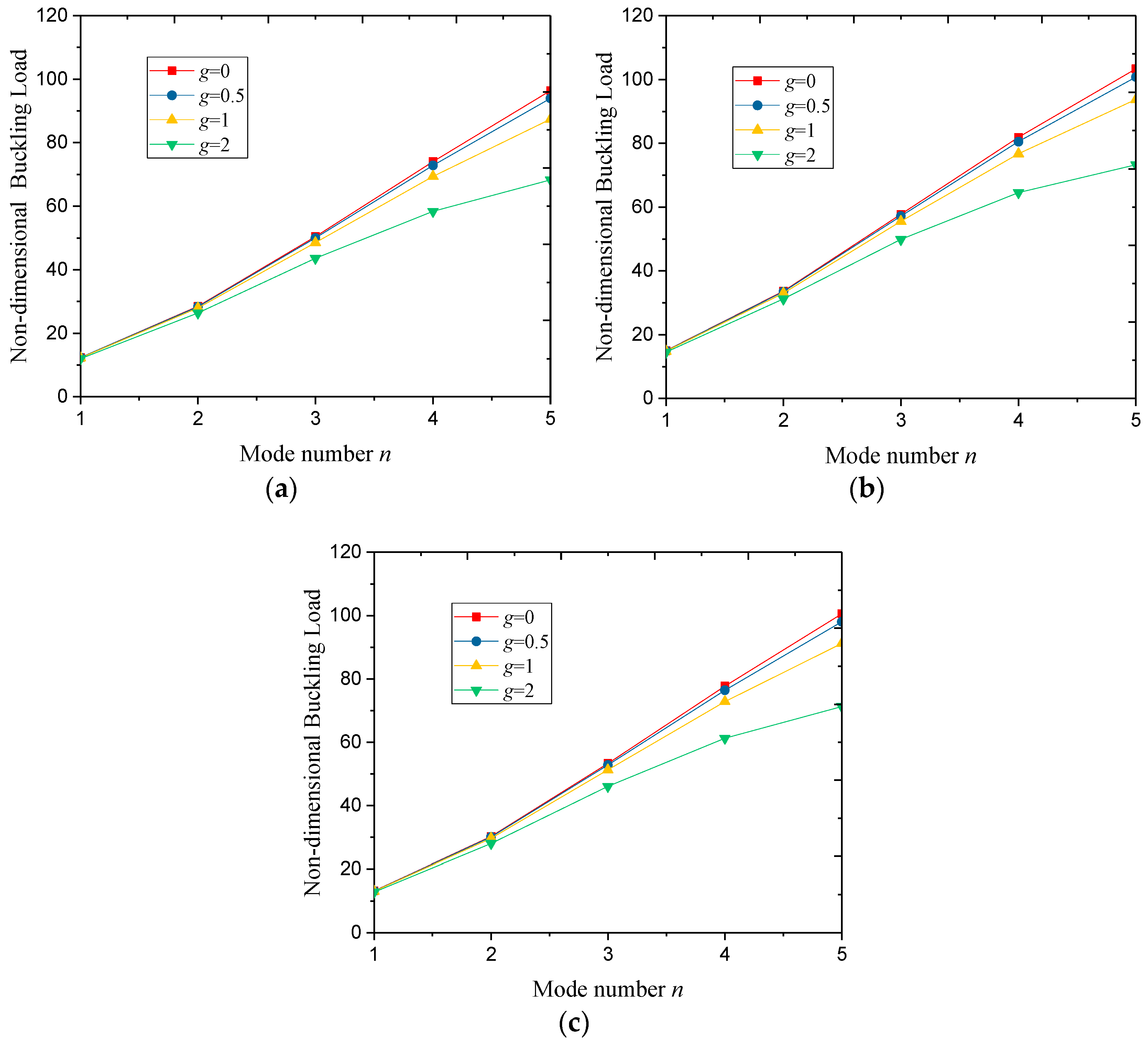
Coatings 08 00389 g003
Figure 4. Variation of the non-dimensional buckling load with a mode number n of square FG nanoporous nanoplate (m = 1, h = 5 nm, ζ = 1, la = lb = 50 nm, λ = 0.5): (a) UD, (b) NUD1, (c) NUD2.
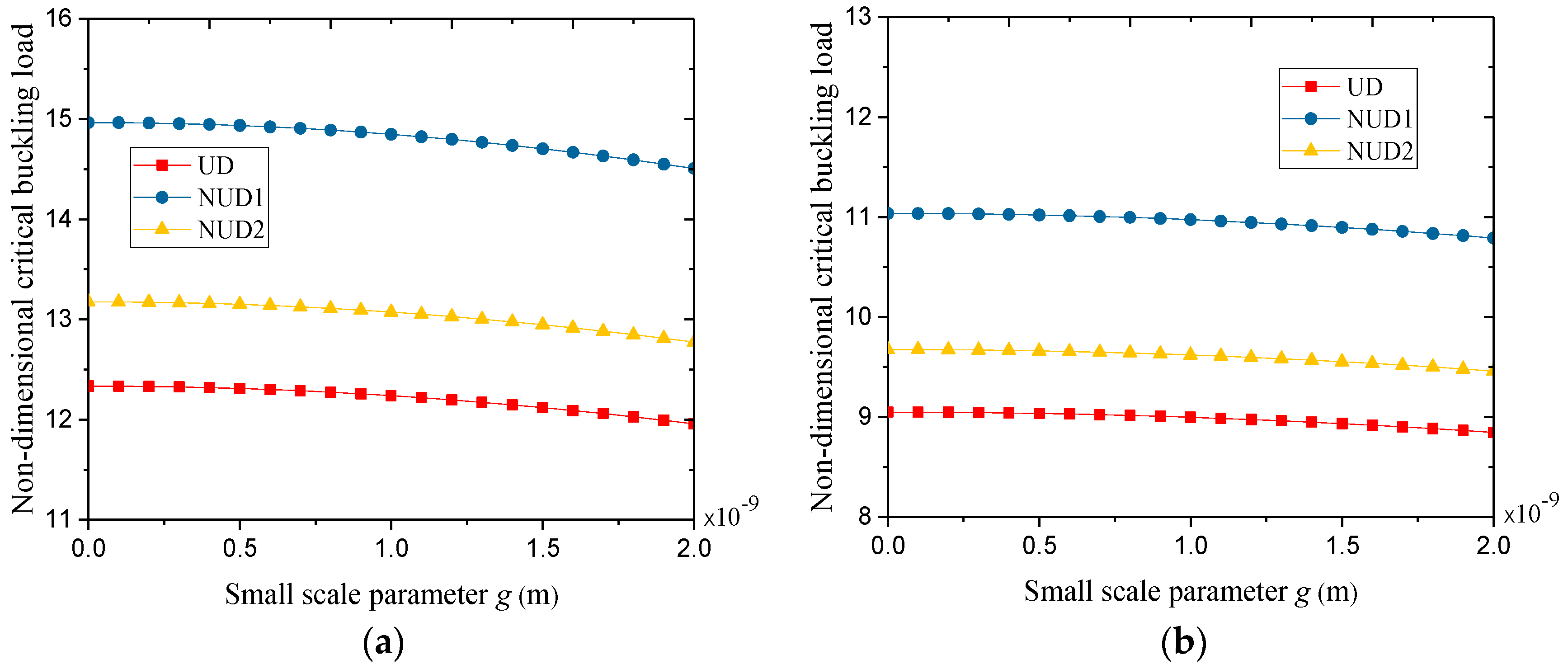
Coatings 08 00389 g004
Figure 5. Variation of non-dimensional critical buckling load with a small-scale parameter g: (a) square nanoplate (la = lb = 50 nm), (b) rectangular nanoplate (la = 50 nm, lb = 75 nm).
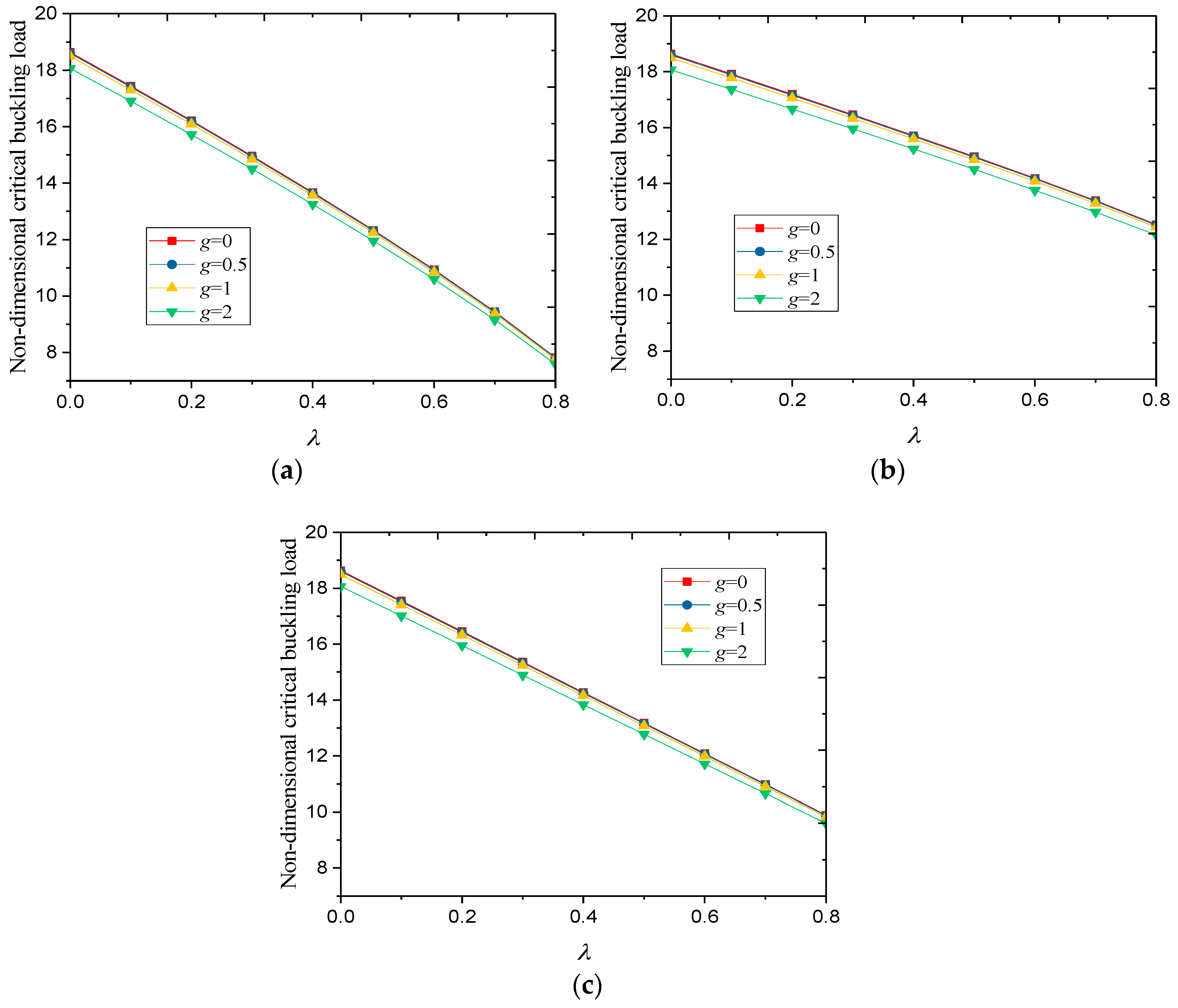
Coatings 08 00389 g005
Figure 6. Variation of non-dimensional critical buckling load with a porosity coefficient λ (m = n = 1, h = 5 nm, la = lb = 50 nm, ζ = 1): (a) UD, (b) NUD1, (c) NUD2.
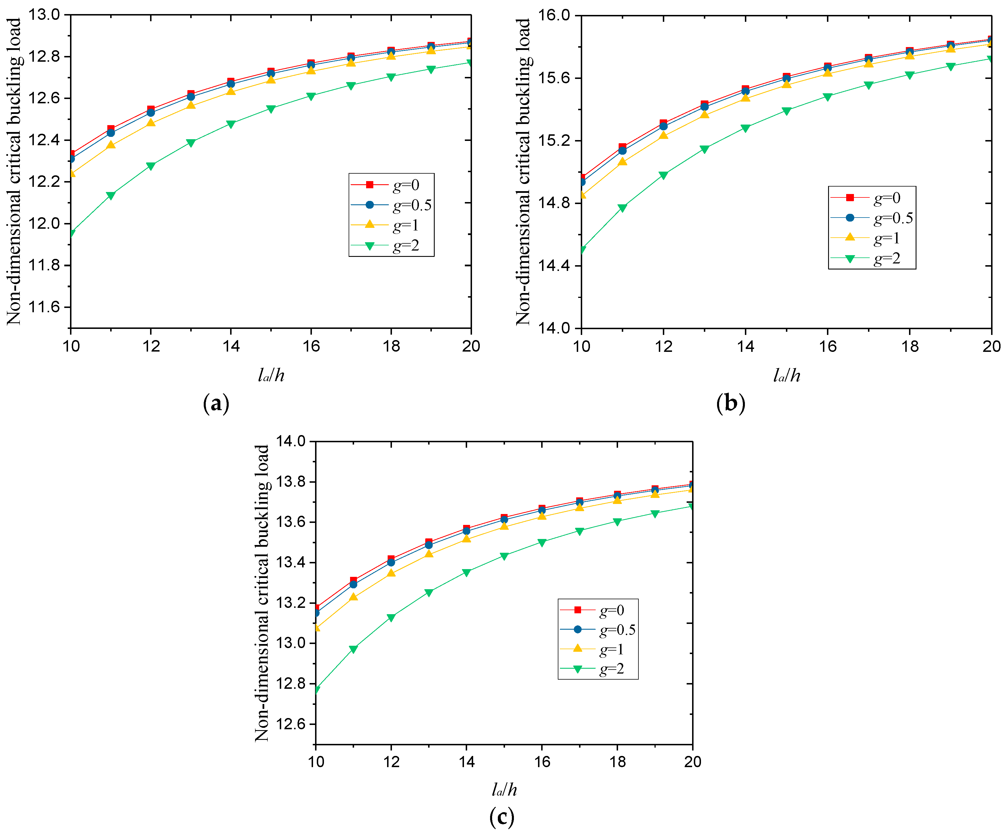
Coatings 08 00389 g006
Figure 7. Variation of non-dimensional critical buckling load with a length-to-thickness ratio of square FG nanoporous nanoplate (m = n = 1, h = 5 nm, la = lb, ζ = 1, λ = 0.5): (a) UD, (b) NUD1, (c) NUD2.
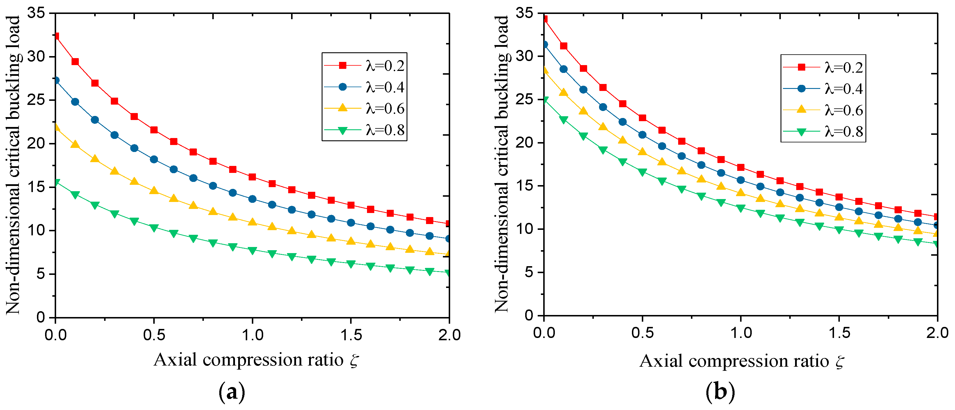
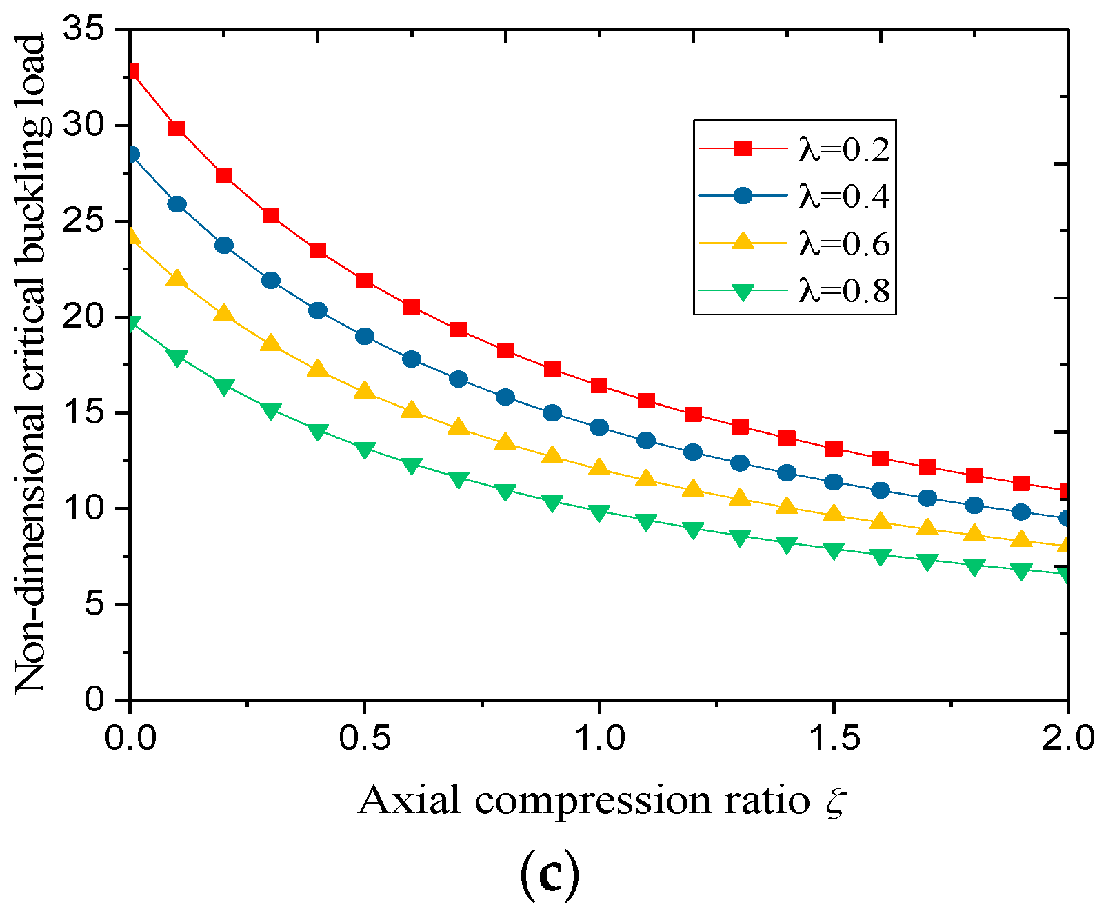
Coatings 08 00389 g007
Figure 8. Variation of the non-dimensional critical buckling load with the axial compression ratio ζ of the square FG nanoporous nanoplate (m = n = 1, h = 5 nm, la = lb = 50 nm, g = 0.5): (a) UD, (b) NUD1, (c) NUD2.
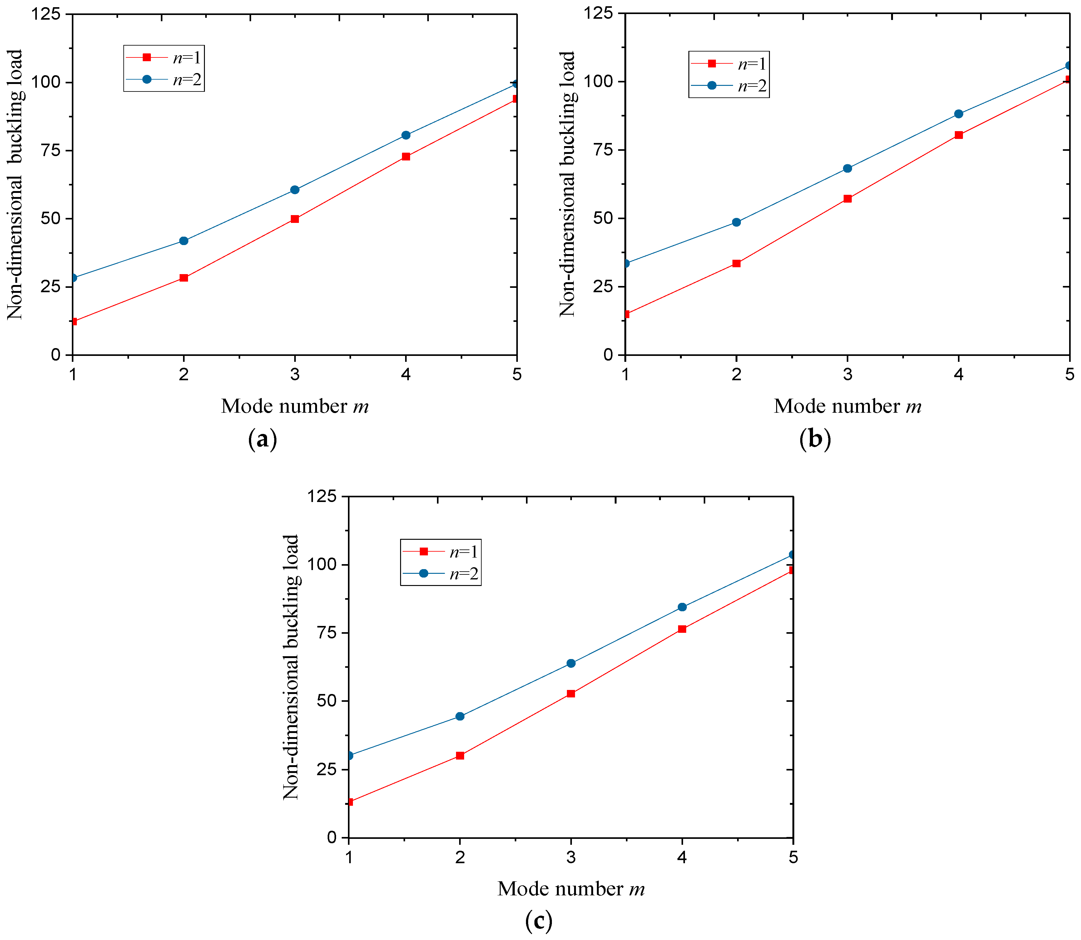
Coatings 08 00389 g008aCoatings 08 00389 g008b
Figure 9. Variation of the non-dimensional buckling load with mode number m (ζ = 1, h = 5 nm, g = 0.5, la = lb = 50 nm, λ = 0.5): (a) UD, (b) NUD1, (c) NUD2.
Coatings 08 00389 g009
Table 1. The non-dimensional buckling loads with different mode numbers, small scale parameters and porosity distributions of square FG nanoporous nanoplate (la = lb = 50 nm, h = 5 nm, ζ = 1, λ = 0.5).
ModeSolid MetalUDNUD1NUD2
g = 0g = 0.5g = 0g = 0.5g = 0g = 0.5g = 0g = 0.5
m = 1, n = 118.63618.60012.33412.31014.96514.93613.17613.150
m = 2, n = 263.87063.37042.27241.94148.96548.58244.77744.426
m = 3, n = 3116.14114.1276.86975.52784.67283.19480.64879.241
m = 4, n = 4163.06158.07107.92104.61113.99110.50112.29108.85
m = 5, n = 5201.03191.57133.05126.79136.20129.79137.56131.09
Table 2. The non-dimensional buckling loads with different mode numbers, small scale parameters and porosity distributions of rectangular FG nanoporous nanoplate (la = 50 nm, lb = 75 nm, h = 5 nm, ζ = 1, λ = 0.5).
ModeSolid MetalUDNUD1NUD2
g = 0g = 0.5g = 0g = 0.5g = 0g = 0.5g = 0g = 0.5
m = 1, n = 113.67213.6529.04859.035711.03611.0209.67519.6613
m = 2, n = 248.70948.43232.23832.05537.91537.70034.24434.050
m = 3, n = 392.76291.58761.39460.61669.13568.25964.68763.867
m = 4, n = 4135.87132.8489.92687.92197.28495.11494.01591.919
m = 5, n = 5173.37167.40114.74110.79120.14116.00119.18115.08
Table 3. The non-dimensional critical buckling loads with different surface areas, small scale parameters and porosity distributions of square nanoplate (m = n = 1, h = 5 nm, ζ = 1, λ = 0.5).
Surface AreaSolid MetalUDNUD1NUD2
g = 0g = 0.5g = 0g = 0.5g = 0g = 0.5g = 0g = 0.5
la = lb =30 nm16.95616.86311.22211.16113.22013.14811.92411.859
la = lb =40 nm18.06918.01411.95911.92214.36414.32012.75212.713
la = lb =50 nm18.63618.60012.33412.31014.96514.93613.17613.150
la = lb =60 nm18.96018.93412.54912.53115.31315.29213.41913.400
la = lb =70 nm19.16119.14112.68112.66915.53115.51513.56913.556
Table 4. The non-dimensional critical buckling loads with different thicknesses, small scale parameters and porosity distributions of square nanoplate (la = lb = 50 nm, m = n = 1, ζ = 1, λ = 0.5).
hSolid MetalUDNUD1NUD2
g = 0g = 0.5g = 0g = 0.5g = 0g = 0.5g = 0g = 0.5
h = 5 nm18.63618.60012.33412.31014.96514.93613.17613.150
h = 6 nm18.19018.15412.03912.01514.49114.46312.84212.817
h = 7 nm17.68917.65411.70711.68413.96913.94112.46912.444
h = 8 nm17.14517.11111.34711.32513.41113.38512.06412.040
h = 9 nm16.56816.53510.96510.94412.83212.80611.63711.614
Table 5. The non-dimensional critical buckling loads with different thicknesses, small scale parameters and porosity distributions of rectangular nanoplate (la = 50 nm, lb = 75 nm, m = n = 1, ζ = 1, λ = 0.5).
hSolid MetalUDNUD1NUD2
g = 0g = 0.5g = 0g = 0.5g = 0g = 0.5g = 0g = 0.5
h = 5 nm13.67213.6529.04859.035711.03611.0209.67519.6613
h = 6 nm13.43013.4118.88838.875710.77610.7619.49369.4801
h = 7 nm13.15513.1368.70628.693910.48410.4699.28799.2747
h = 8 nm12.85112.8338.50538.493210.16710.1529.06149.0485
h = 9 nm12.52412.5068.28878.27699.82979.81578.81798.8053
Table 6. The non-dimensional critical buckling loads with different aspect ratios, small scale parameters and porosity distributions of nanoplate (m = n = 1, la = 50 nm, h = 5 nm, ζ = 1, λ = 0.5).
lb/laSolid MetalUDNUD1NUD2
g = 0g = 0.5g = 0g = 0.5g = 0g = 0.5g = 0g = 0.5
0.542.99442.78328.45628.31633.66233.49730.25930.110
118.636418.60012.33412.31014.96514.93613.17613.150
1.513.67213.6529.04859.035711.03611.0209.67519.6613
211.89711.8827.87397.86429.62159.60978.42198.4116
2.511.06911.0567.32587.31748.95978.94947.83697.8280

