Article

Anti-Fouling Ceramic Coating for Improving the Energy Efficiency of Steel Boiler Systems

1
Energy Materials Centre, Korea Institute of Ceramic Engineering and Technology, Jinju 52851, Korea
2
Department of Ceramic Engineering, Gyeongsang National University, Jinju 52828, Korea
3
Advanced Institute for Science and Technology (AIST), Hanoi University of Science and Technology (HUST), No. 01, Dai Co Viet Road, Hanoi, Vietnam
*
Author to whom correspondence should be addressed.
Coatings 2018, 8(10), 353; https://doi.org/10.3390/coatings8100353
Submission received: 26 July 2018 / Revised: 21 September 2018 / Accepted: 28 September 2018 / Published: 2 October 2018
(This article belongs to the Special Issue Advanced Coatings for Buildings)

Abstract

:
Boilers are systems used mainly to generate steam in industries and waste-to-energy facilities. During operation, heat transfer loss occurs because a fouling layer with low thermal conductivity is deposited on the external surfaces of the boiler tube system, which contributes to the overall poor energy efficiency of waste-to-energy power plants. To overcome the fouling problem, a ceramic coating was developed and applied to carbon steel with a simple and inexpensive coating method. Anti-fouling testing, thermal conductivity measurement, and microstructure observation were performed to evaluate the performance of the coating. All evaluated properties of the coating were found to be excellent. The developed ceramic coating can be applied to boiler tubes in a real facility to protect them from the fouling problem and improve their energy efficiency.

1. Introduction

Energy conservation and environmental protection are currently very important issues worldwide. Municipal solid waste (MSW), which is an inevitable product of modern society, is one of the most serious urban pollution sources and one of the greatest challenges for future generations. Deep concerns over global warming have led to numerous studies on energy efficiency and renewable energy [1]. MSW can be converted to an eco-friendly renewable resource that not only produces energy but also significantly reduces the greenhouse gas emissions from landfills. A waste-to-energy (WTE) incineration plant recovers energy from MSW and produces electricity and/or steam for heating [2]. For a WTE plant, the energy efficiency can be improved and CO2 emissions be reduced by improving the heat efficiency of the boiler system because this is the main method for heat transfer. However, one of the most serious problems in WTE facilities is that unwanted mineral matter such as slagging and fouling is always deposited on the heating surfaces of the boiler. As a general definition, fouling is the deposition and accumulation of unwanted materials such as scale, algae, suspended solids, and insoluble salts on the internal or external surfaces of processing equipment, including boilers and heat exchangers [3]. In WTE plants, ash fouling is the result of several physical and chemical processes. Ash fouling, which causes serious corrosion and erosion problems, builds up on the heat transfer surfaces of boilers to act as an insulator; this greatly reduces the global heat transfer of the boiler and minimizes the yield of the plant [4]. In one study, a typical 1–1.5 mm fouling build-up on the boiler surface can increase fuel consumption by about 3%–8% [4,5]. In another study, a 0.03 in (0.8 mm) thick fouling layer caused a 9.5% reduction in the heat transfer, and a fouling layer thickness of 0.18 in (4.5 mm) caused a 69% reduction in an extreme case [6]. When this occurs, the boiler heat transfer surface should be cleaned. However, the operating costs from working to clean fouling is extremely high. Therefore, it is necessary to prevent the deposition and accumulation of unwanted matter on the boiler.
A small improvement in the boiler efficiency will clearly help save a large amount of fuel and to reduce CO2 emissions. In a literature review, many researchers were found to have focused on improving boiler efficiency. For example, Gopal et al. [7] studied losses in boilers. Nussbaumer et al. [8] reported a measure to save boiler energy by improving the combustion efficiency. Gao et al. [9] and Karell et al. [10] investigated the role of maintenance on boiler energy conservation. Most of these researchers did not study methods to control or prevent the formation of a fouling layer on the heating surface of a boiler. To address this shortcoming of previous approaches, an anti-fouling coating to prevent ash from attaching was developed in this study to protect boilers from fouling agents and increase their thermal conductivity efficiency.
Among the various coating systems used for boiler systems, polymer-derived ceramic coatings (PDCs), glass, and glass–ceramic coatings have the advantages of chemical inertness, high temperature stability, and superior mechanical properties compared to other materials suitable for spraying [11]. Moreover, advanced thermal spraying processes such as plasma spray and high-velocity oxy-fuel (HVOF) are also typically used to deposit coatings on the surface of boilers to enhance their high-temperature oxidation resistance but they are quite expensive because of high energy consumption [12]. Until now, however, most coating techniques just focused on improving the wear, oxidation, and corrosion resistance of the boiler surface [13,14,15,16,17]. Few have been used to mitigate and prevent fouling problems. In this study, an anti-fouling ceramic coating was developed for application to the external surfaces of a boiler by using a low-cost slurry spray coating method.

2. Material and Methods

The experimental procedure was performed as follows: (i) prepare the starting materials and ceramic coating materials, (ii) apply the ceramic coating materials to the steel substrates, (iii) cure and heat-treat the coated substrates, and (iv) characterize and evaluate the coatings.

2.1. Starting Materials and Ceramic Coating Preparation

JIS S45C steel is the most common material used in boiler tubes and was used in this experiment. Table 1 presents the chemical composition. Steel plates with dimensions of 10 mm × 10 mm × 2 mm were cut and then cleaned in ethanol to remove all dust and oil from their surfaces prior to coating deposition.
Potassium silicate (water glass with concentration of 37 wt %–a product of Young Il Chemical Co., Ltd., City, Country) was used as a binder because of its strong bond with the steel substrate. To enhance the properties of the coating slurry, several kinds of active and passive fillers with particle sizes of 2–25 µm were added to the binder. Table 2 lists some of their properties. Günthner et al. [18] selected some passive fillers (BN; Si3O4; ZrO2) to enable the processing of thick, dense, and crack-free composite coating systems. In our present study, passive fillers (Al2O3; SiO2) were used due to their good compatibility with the alkali silicate glass and low oxygen permeability to enhance high-temperature oxidation resistance of steel. By adding these fillers, it is possible not only to generate coating with high thermal conductivity than glass coating but also to reduce the volume change of glass binder during crystallization at high temperature [18]. The dissolution of the Al2O3 and SiO2 inclusions turned the binary glass (K2O–SiO2) into a ternary glass (K2O–Al2O3–SiO2) which may improve the chemical stability of the glass [19]. Active filler (flake Al) was added to achieve crack-free coating. In the meantime, CoO and NiO was doped to improve the adhesion between the coating and substrate and reduce the porous structure of the coating [11,20]. Various parameters such as the mass fraction of the fillers, the viscosity, the dispersing methods were varied to optimize the coating system. As a result, a mixture of binder and fillers with the chemical composition listed in Table 3 was then mixed with a mixer. The mixture was ground at 400 rpm for 240 min using a ball mill such that the fillers were dispersed homogeneously in the binder. Finally, a coating slurry with solid concentration of 43 wt % was filtered and stored.
The ceramic coating was sprayed on the steel plates by an air gun (W-71, Anest Iwata, Taiwan). The steel specimens were placed about 15–20 cm in front of the gun nozzle. All surfaces of the steel substrates were sequentially covered with the glass ceramic slurry by changing the surface facing the gun nozzle. To obtain a thicker glass ceramic coating, the spraying process was performed twice. Next, the specimens were cured for 2 h at 95 °C and finally sintered in a box furnace at 800 °C for 24 h. The sintered temperature was selected based on the real operating temperature of a boiler in a WTE plant.

2.2. Fly Ash and Coating Characterization

Four fly ashes from four different Korean incinerators were considered because they were very rich in alkali, chlorine, and calcium. The fly ash samples were analyzed at the Test & Standard Center of Korea Institute of Ceramic and Engineering (KICET) by scanning electron microscopy (SEM) equipped with backscattered and secondary electron detectors coupled with energy-dispersive X-ray spectroscopy (EDS) (SEM; JSM-6700F, JEOL, Tokyo, Japan), X-ray diffraction (XRD), a laser diffraction particle size analyzer (PSA) (Mastersizer S Ver. 2.15, Malvern Instruments, Malvern, UK), and inductively coupled plasma optical emission spectrometry (ICP-OES) (Perkin Elmer OPTIMA 8300, PerkinElmer, Inc., Waltham, MA, USA).
The coatings were observed with a camera (EOS 600D, Canon, Tokyo, Japan) to determine the macroscopic morphology and then further investigated by an optical microscopy. SEM-EDS and XRD were used for the microstructure characterization. To prepare cross-sectional surfaces for SEM observation, standard metallographic polishing techniques were performed; the coated specimens were cold-mounted in epoxy resin and then sequentially polished with 200, 800, 1200, and 2000 grit SiC abrasive paper.

2.3. Adhesion and Thermal Shock Testings

In the present work we used cross-cut tape test (ASTM D3359) [21] and pull-off test (ASTM D4541) [22] to obtain the adhesion between the coating and the substrate. For thermal shock testing, the coated specimen was subjected to 800 °C in a furnace for 5 min and subsequently removed using a pair of pliers and placed in a water tank (20 °C) for 5 min. The process was repeated and the total number of thermal cycles was determined up to the time when macroscopic cracks or failure appeared.

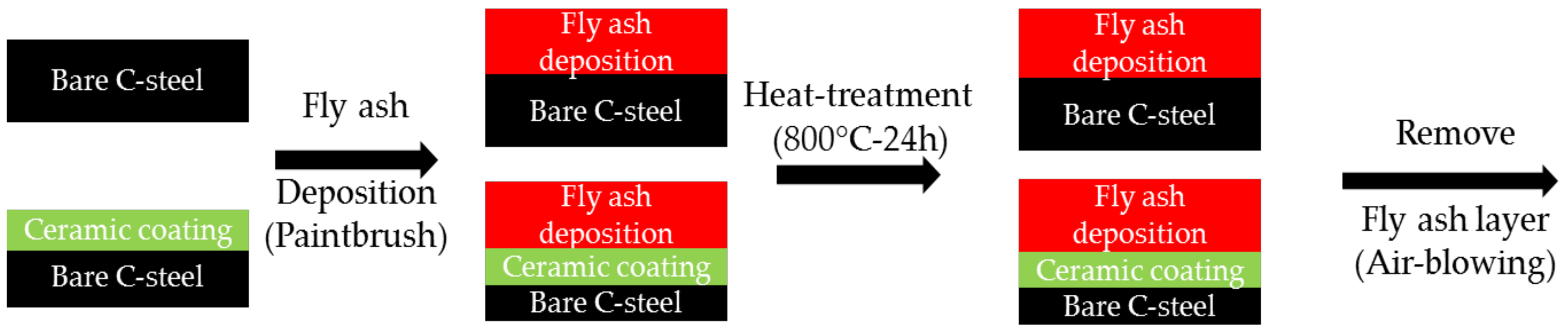
2.4. Anti-Fouling Testing

The anti-fouling performance of the developed coating against fly ash was studied. To study the anti-fouling ability of the coating, the slurry containing ash was used to observe the ash attachment on the coating surface. To do this, coated and non-coated steel plates were immersed in the fly ash solution and then dried at 50 °C for 1 h. After 24 h of sintering in the box furnace at 800 °C for 24 h, the specimens were cooled to room temperature (20–25 °C). A compressed air gun (0.5 MPa) was then used to blow the fly ash powder-deposited surface of each specimen for 1 min. The air gun nozzle was placed 20 cm away from the specimens. Subsequently, the air-blown specimens were examined with SEM-EDS. Figure 1 shows the entire experimental process. In addition, the prepared composite coatings were applied to a real-life boiler system to assess their effectiveness.

2.5. Thermal Conductivity Measurement

To evaluate the energy efficiency, four different specimens were prepared comprising: (i) steel with ceramic coating; (ii) steel without ceramic coating; (iii) ceramic coating materials and (iv) corrosion specimen. Here, specimens (i) and (ii) were then subjected to anti-fouling testing. Specimen (iii) was a bulk material made from the mixture of slurry coating. Specimen (iv) was separated from the ash deposits attached to the boiler systems at JINJU INDUSTRY power plant. All the specimens were made in size of 10 mm × 10 mm × 1.2 mm and their thermal conductivity were measured with the laser-flash method (Netzsch LFA 427, Netzsch, Wittelsbacherstraβe, Germany). To assess the thermal conductivity λ (W/m·K) of a specimen, the thermal diffusivity a (mm2/s), density ρ (g/cm3), and specific heat C p (J/g·K) of the specimen must be known. The thermal diffusivity was measured with the heating rate 5 K/min. The data was recorded after each 100 °C from 25 to 800 °C. The specific heat C p of the specimen was estimated by simple rule of mixture of the fillers and the coating matrix. The density of the specimen was determined using Archimedes principle.
λ ( T ) = C p ( T ) × a ( T ) × ρ ( T )

3. Results and Discussion

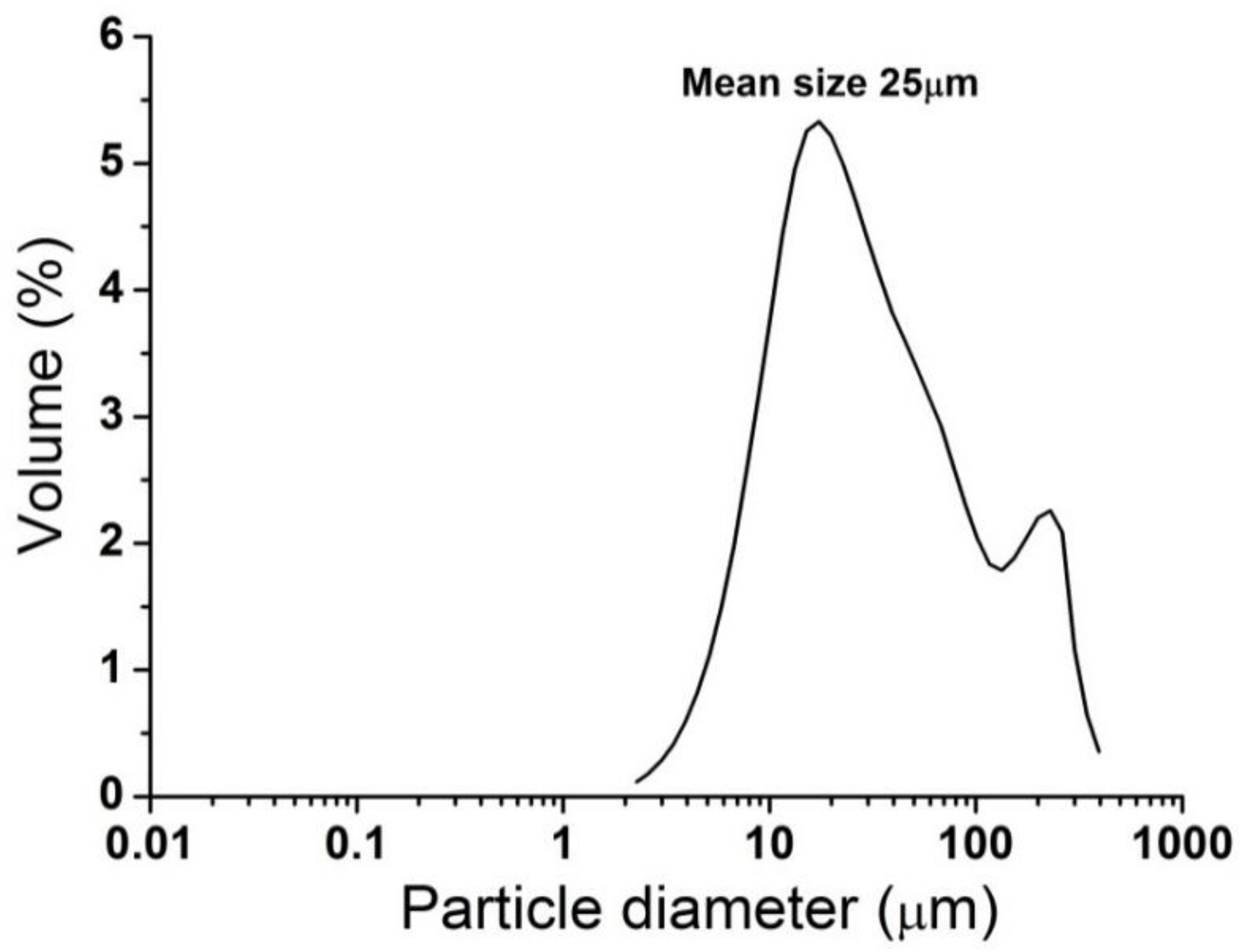
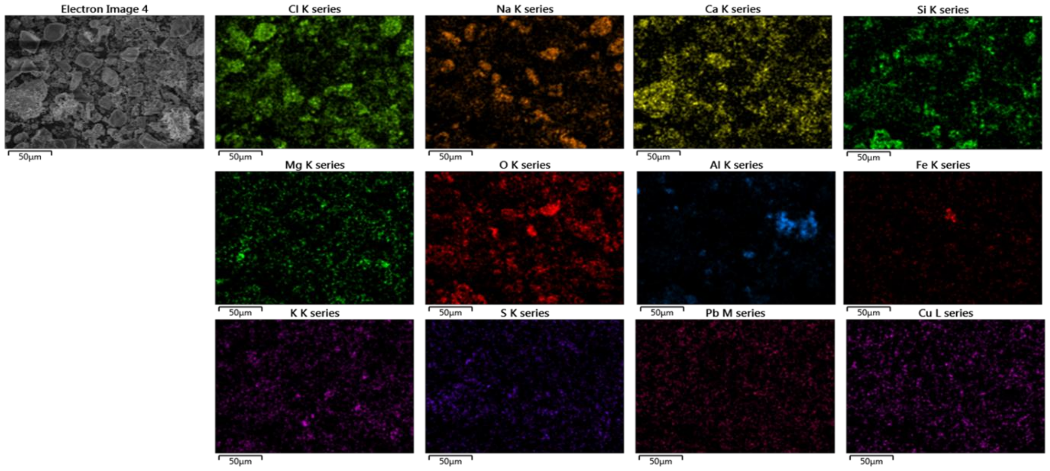
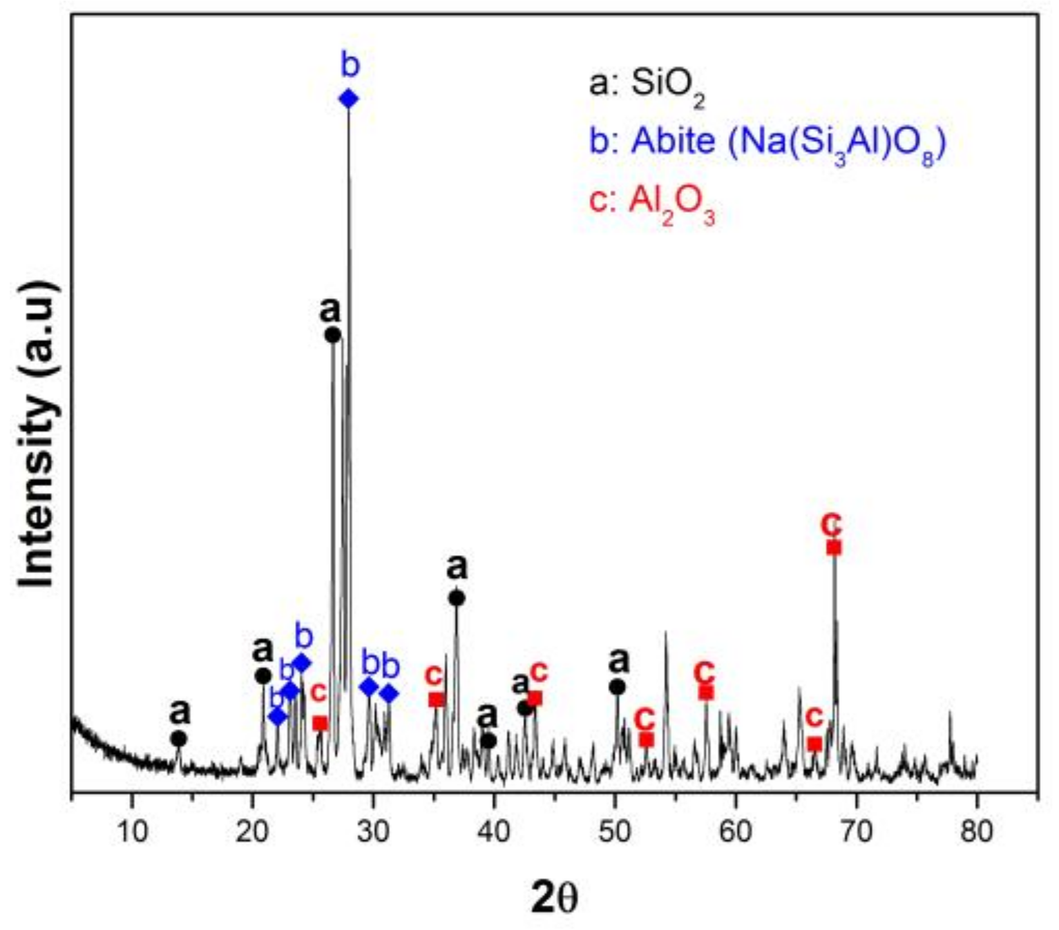
3.1. Properties of Fly Ashes

To date, various studies have investigated the ash deposition characteristics from different perspectives to clarify the influences of individual factors, including the chemical/mineral compositions of the ashes. Wibberley et al. [23] concluded that fine particles (<10 µm) with a high content of alkali vapors, including sodium and potassium, are the main reason for the inner layer formed in the initial stage of ash deposition. Lee et al. [24] stated that high concentrations of chlorine and sulfur in MSW affect the rate of corrosion in WTE boilers. Furthermore, accumulated ash with a high chlorine concentration on tube surfaces may lead to corrosion underneath the deposit [25,26].
The composition of MSW varies because of differences in lifestyle, so the ash content also varies. Generally, the chemical compositions of the fly ashes showed that SiO2, Al2O3, Fe2O3, CaO, and Na2O were the main oxides (Table 4). Lead and copper were the most common heavy metals in the ashes (Table 5). Based on previous studies, fly ash 1 (Table 4 and Table 5), which has high sodium and chlorine contents, was selected as the fouling matter. The physical and chemical properties of fly ash 1 were examined in more detail. The mean size of fly ash 1 was 25 µm (Figure 2). The elemental concentrations of fly ash 1 as determined by SEM-EDS (Figure 3) were consistent with the results from ICP-OES (Table 4 and Table 5).

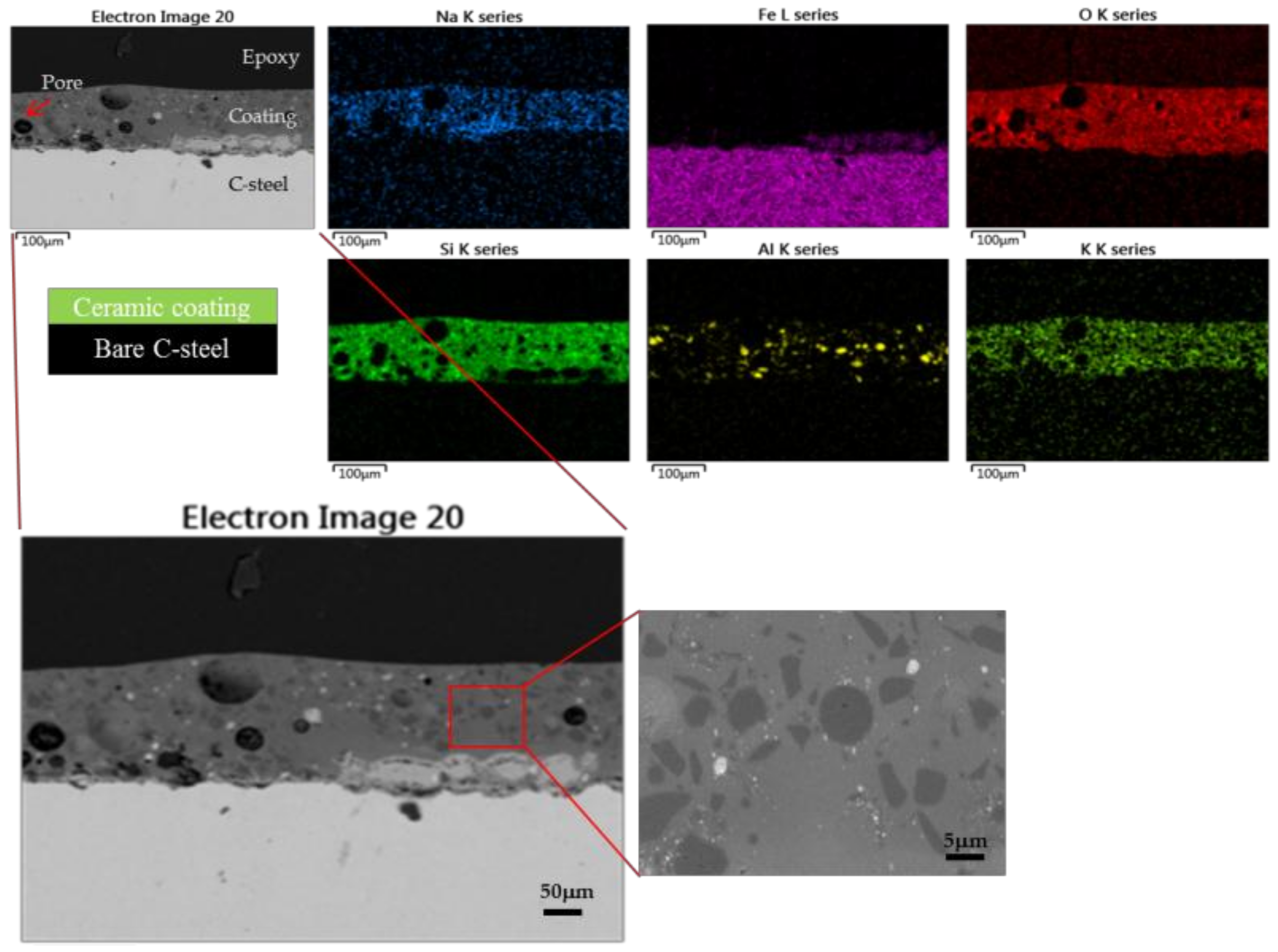
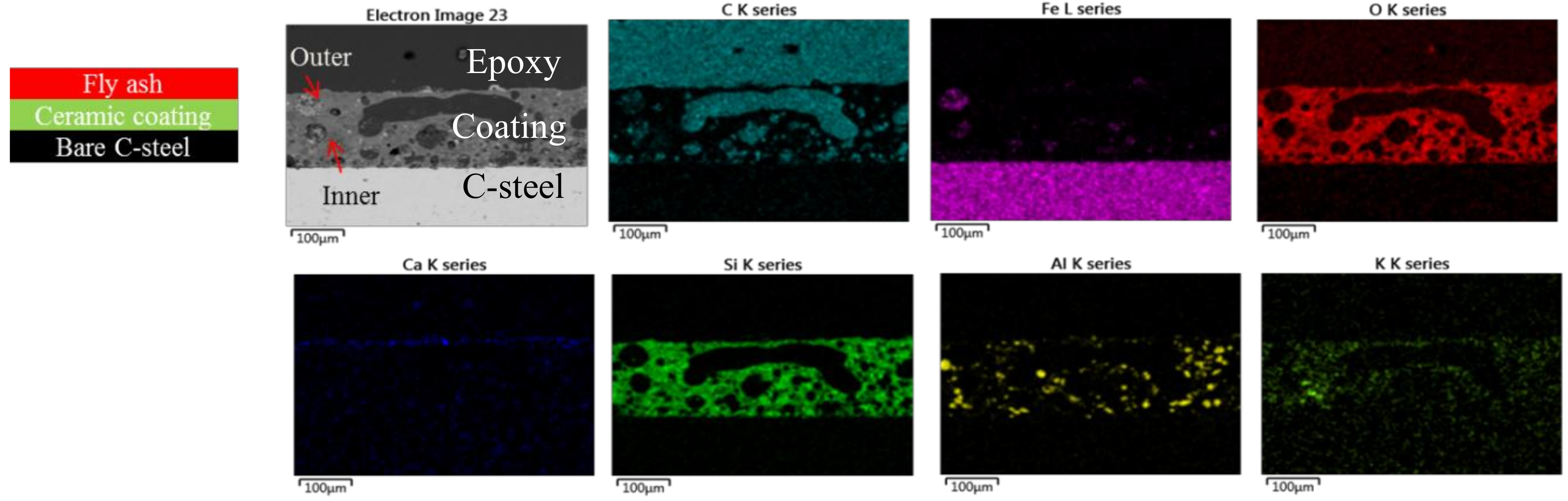
3.2. Microstructure and Morphology of Ceramic Coating

The XRD patterns of the composite coating on steel substrate are shown in Figure 4. SiO2, Al2O3, and abite Na(Si3Al)O8 peaks were detected. Abite may be the new phases formed during thermal treatment. Because the softening point of glass (640–680 °C) is lower than its heat treatment temperature (800 °C), the glass would soften, flow, and spread well on the steel surface. The fillers may be partially dissolved into the glass matrix and it is not surprising that the reactions between glass and fillers may be occurred during thermal treatment.
Generally, the coating should have a relatively low surface energy and a dense structure to significantly reduce the sticking of molten ash particles to the surfaces. Moreover, it should have an appropriate thickness and have no chemical affinity with the fouling matter. Finally, it must have good adhesion with the boiler. Figure 5 shows the cross-section morphology of the heat-treated ceramic coating with a thickness of 150–160 µm. A layer enriched with silicon and aluminum in the cross-section was observed. Additionally, the coating was intact and only a few closed pores with spherical shape were seen. These certain pores can help alleviate thermal stress and thermal expansion mismatch between the coating and substrate. No cracks in the coating or interlayer at the coating–steel interface were observed, which suggests that the coating has a thermal expansion coefficient (CTE) similar to that of the steel and had a strong chemical bond with the steel [26,27]. The adhesion between the coating and steel was measured in detail as follows.

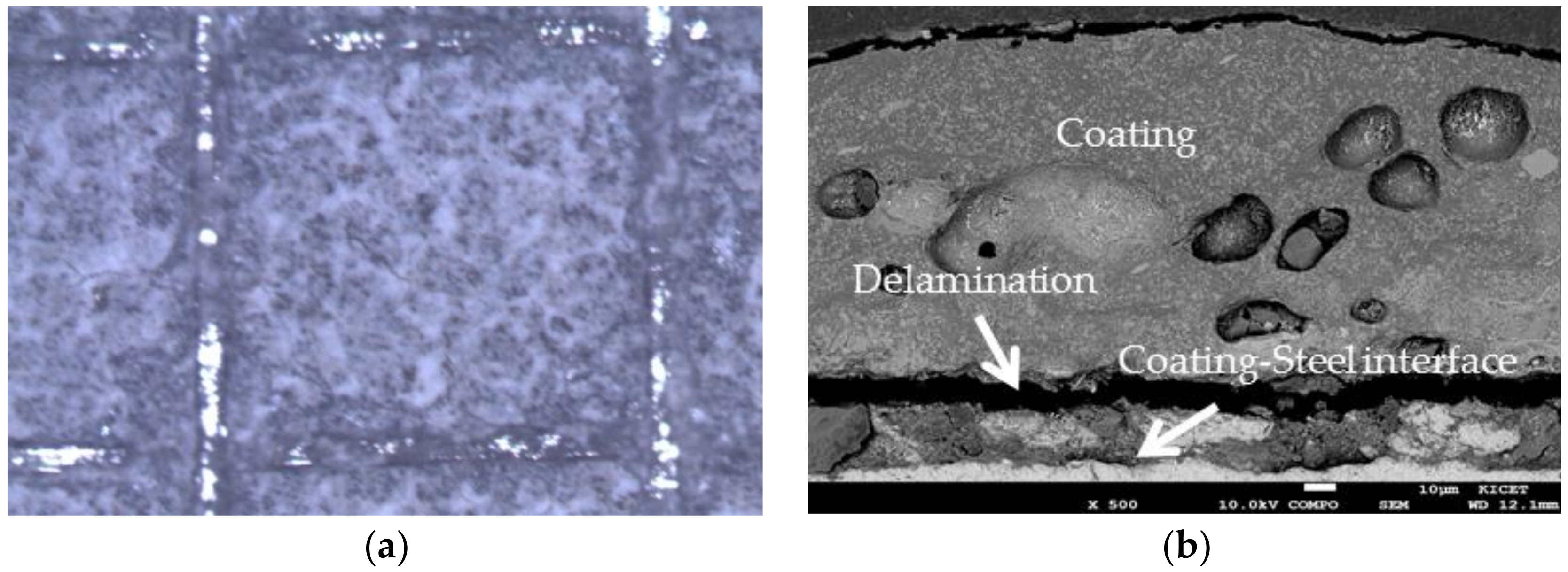
3.3. Adhesion and Thermal Shock Properties
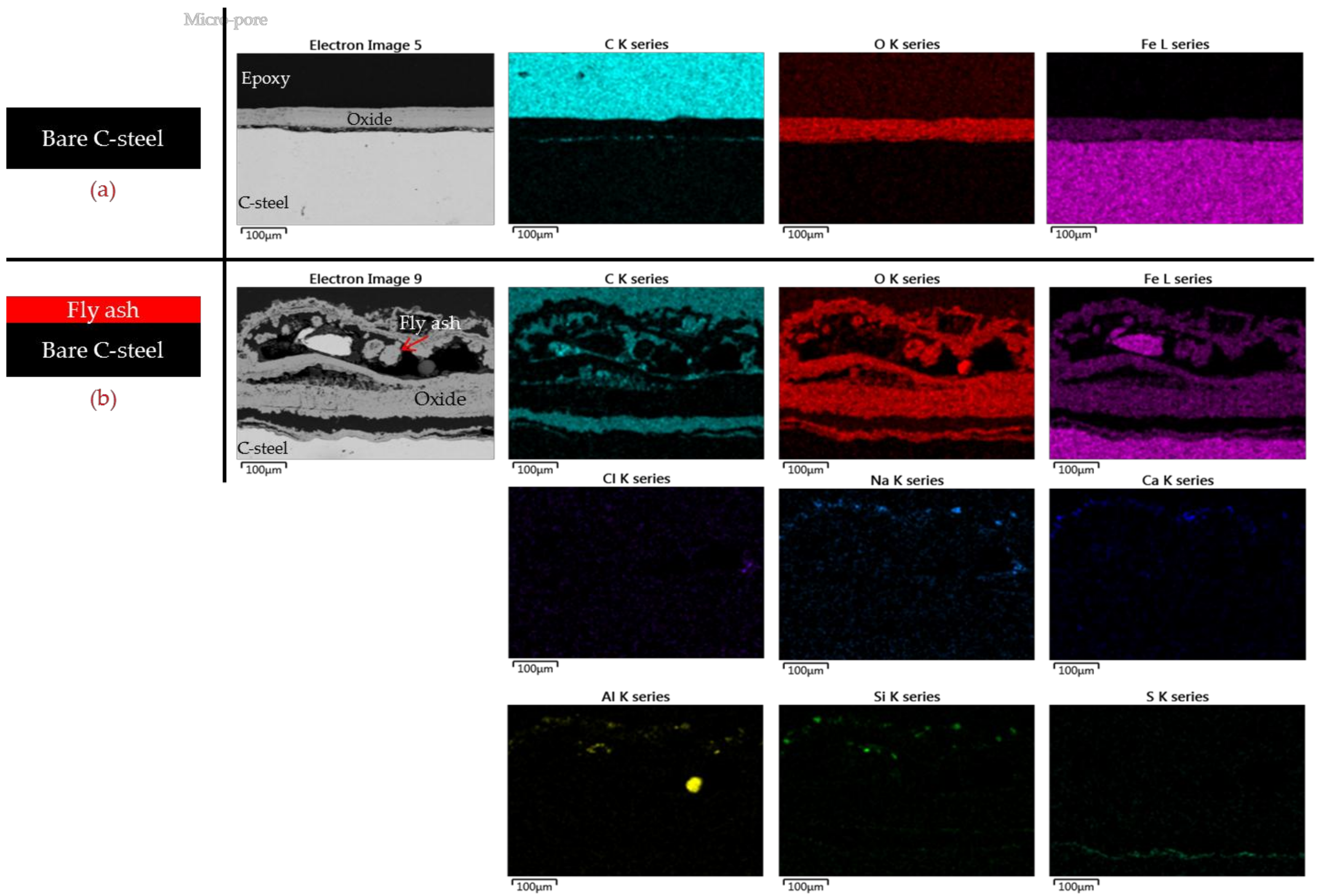
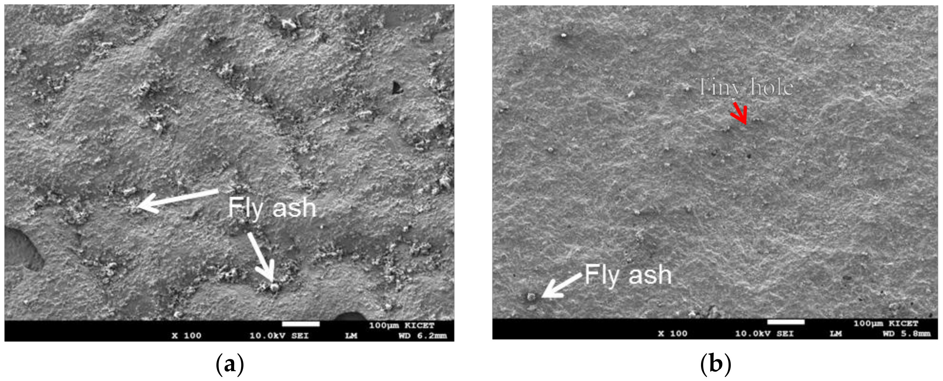
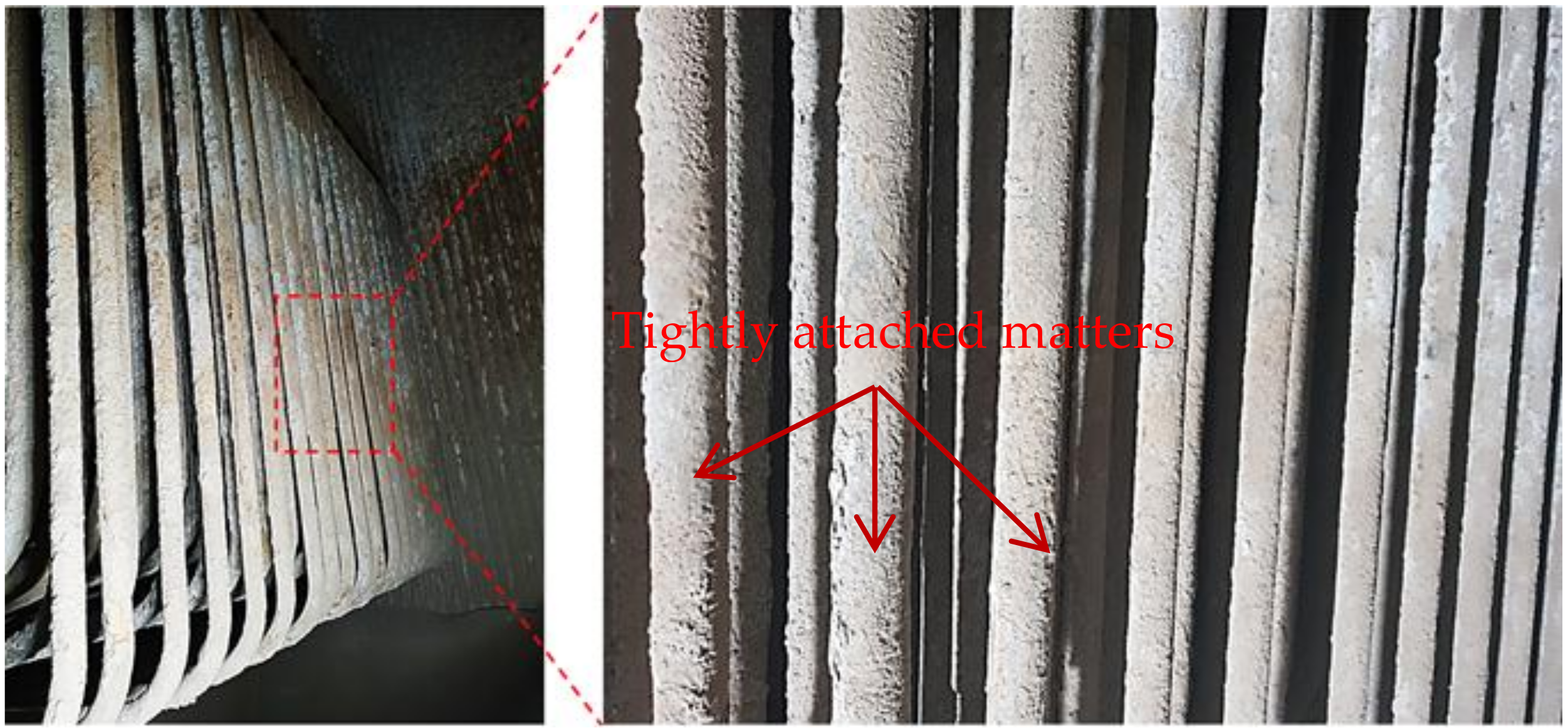
Cross-cut tape test (ASTM D3359) [21] was first chosen for qualitative estimation, and pull-off test (ASTM D4541) [22] was then carried out to quantify the adhesion of the coatings. In cross-cut tape test, a grid of square scratches was made on the coating surface. Optical microscopy was used to evaluate about the adhesion of the coating. As shown in Figure 6a, the edges of the scratches are completely smooth and none of them is detached. According to standard ASTM D3359, the highest adhesion scale (5B) is referred to the coating. In pull-off test, the adhesive glue used in this work is Araldite 2021 with flexural strength more than 26 MPa. The glued specimens were cured at room temperature for 30 min. The specimens were mounted on testing machine and were pulled in a direction normal to the coating surface at a constant speed 0.013 mm/s until failure occurs. When failure occurs, the maximum load was recorded. As a result, the interface failure occurred in the 27–29 MPa range. Figure 6b shows cross-sectional SEM of coating after the pull-off test. A delamination appeared near the coating–steel interface, i.e., failure surface occurred within the coating. This is referred as a cohesive failure of the coating. Good adhesion of the coating is ascribed to an interdiffusion at the glass-steel interface due to the mobility of some metal ions in the glass and the metal atoms of the steel at high temperature. Metal ions from the glass will diffuse into the metal while metal atoms will diffuse into the glass.
The thermal shock resistant test was examined in water quenching. The coated specimen was heated to 800 °C for 5 min and then cooled rapidly in water (20 °C) for 5 min. After ten uninterrupted thermal cycles no macroscopic cracks or failure are visible. The good thermal shock resistance of the coating is an evidence to suggest that the CTE composite coating is close to that of the steel [18]. Some small spherical pores distributed in the coating are the reason for relaxing thermal stresses and improve the thermal shock resistance of the coated samples.

3.4. Anti-Fouling

Figure 7a,b present the cross-sections of the non-coated steel plate without and with ash particulate deposited, respectively. As depicted in Figure 7a, bare C-steel experienced breakaway oxidation behavior at 800 °C with the top surface of oxide layer was very intact. On the contrary, in case of exposure with fly ashes (Figure 7b), the top surface of oxide layer was seriously damaged with many hollow blisters. The fly ash adhered strongly to the steel, which rapidly increased the fouling rate. A top view of the surfaces (Figure 8) showed that much ash was attached all over the surface of the non-coated steel (Figure 8a). This suggests that the following chemical reaction takes place between the fouling particulates and steel at high temperatures [28]:
3Na2O + Fe → Na4FeO3 + 2Na↑
In contrast, almost no fouling ash adhered on the whole surface of the coated steel (Figure 8b); only some fine fly ash particles stuck in tiny holes were observed. Figure 9 shows that the outer area of the coating was empty of fly ash, while inner area still adhered well to the steel. This demonstrates that the developed ceramic coating provides excellent resistance against the fouling precipitation of fly ash. It could also withstand the high-pressure air jet, which means that a strong bond formed between the coating and steel.

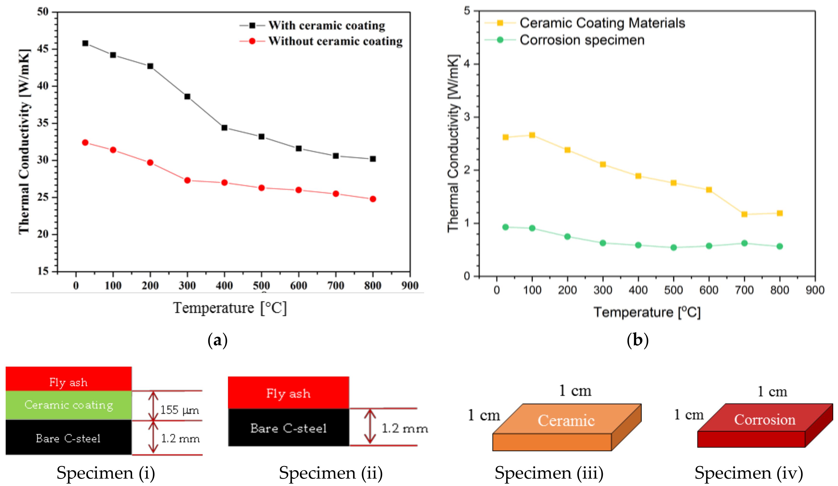
3.5. Thermal Conductivity

Figure 10a describes the thermal conductivity of the coated and non-coated samples as a function of the temperature up to 800 °C. The thermal conductivity of the non-coated steel was ~5 W/mK less than that of the coated steel at 800 °C. Figure 10b indicates the thermal conductivity of the ceramic coating itself and the ash deposited specimen. At 800 °C, the thermal conductivity of the composite coating was 1.2 W/mK which is about twice as high as that of the corrosion specimen (0.6 W/mK). Those values can be explained as follows. The physical structure and microstructure of a surface is believed to affect its thermal conductivity [29,30]. As shown in Figure 7b, the surface of the non-coated steel with highly porous deposits of loose particulate matter had low thermal conductivity. The deposits that formed on the steel surface limited the absorption of the incident radiation and the transfer of this energy to tubes containing the working fluid. Meanwhile, Figure 9 shows that the surface of the coated steel had a dense interconnected structure without fouling deposits, so the thermal conductivity was high. Therefore, thanks to the ceramic coating, the energy efficiency of the boiler tubes was significantly improved.

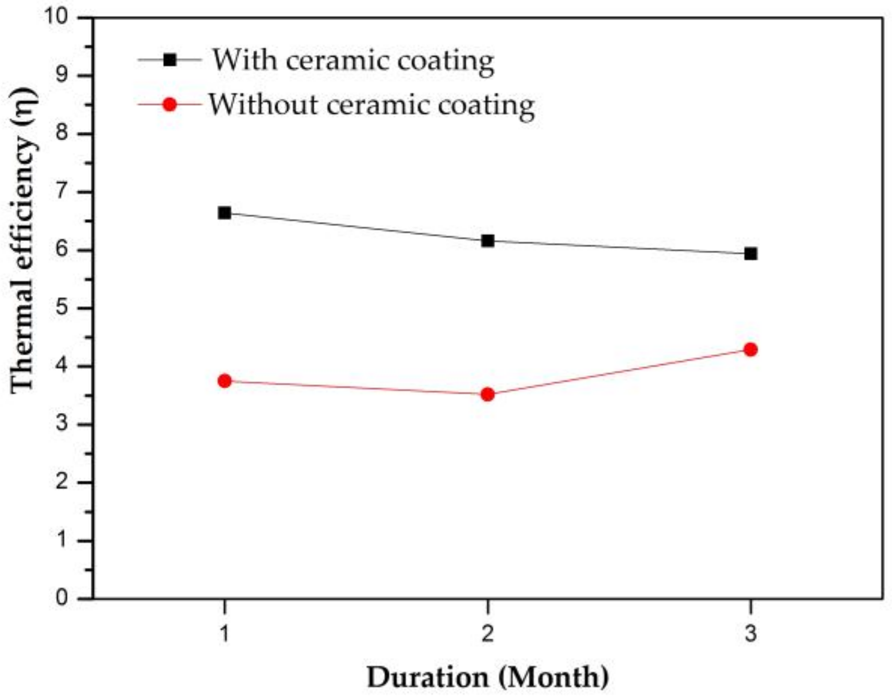
3.6. Application of the Coating

In engineering application, the ceramic coating was applied to the heating surfaces of boiler water-wall tubes of tower 2 at JINJU INDUSTRY power plant in Chungcheongbuk-do province of Korea (Figure 11). The effect of ceramic coating on fouling resistance and energy efficiency was evaluated after 3 months of operation of the boiler. As seen in Figure 11 and Figure 12, a significant difference in the coated and uncoated areas of the boiler surfaces was observed. The coated surfaces were relatively clean with only small amount of unwanted matters attached on a small part of boiler surface. However, it should be noted that, these matters are bonded weakly with boiler surface and they can be easily removed by a low-pressure air gun. Meanwhile, fouling and slagging severely deposited on the uncoated surfaces and it is quite hard to remove them even with a high-pressure air gun.
The thermal efficiency of boilers was calculated before and after applying the composite ceramic coating. To do this, it is useful to check the amount of incinerated waste (input amount or burn fuel) and the amount of produced steam (production amount). For simplicity, thermal efficiency (η) before and after using the coating is defined as the rate of total steam production over the fuel consumption. Figure 13 collected the thermal efficiency without and with using the ceramic coating in the same period, respectively. As can be seen in Figure 13, the thermal efficiency increased about 62.34% after applying the ceramic coating. Of course, there are some other operating conditions can affect the result, but it is worth concluding that the developed ceramic coating has great potential to be applied in real boiler systems to improve their overall thermal efficiency.

4. Conclusions

The purpose of this study was to develop a ceramic coating to prevent the fouling deposition of fly ash. The results can be summarized as follows.
  • A ceramic coating with a thickness of 150–160 µm was successfully developed and applied to carbon steel.
  • Fly ash with high concentrations of sodium and chlorine was selected as the fouling matter. In the anti-fouling testing, the developed ceramic coating with a dense structure performed well at preventing fly ash fouling. In comparison, the bare steel without coating was severely fouled.
  • The ceramic coating showed a significant improvement in the thermal conductivity of the boiler at high temperature (800 °C). Hence, it can help increase the overall energy efficiency for actual application to real boiler systems in WTE facilities.

Supplementary Materials

The following are available online at https://www.mdpi.com/2079-6412/8/10/353/s1. Table S1: Input and output production amount of tower 2 in period of 2017.04–2017.06 (JINJU INDUSTRY’s data); Table S2: Input and output production amount of tower 2 in period of 2018.04–2018.06 (JINJU INDUSTRY’s data).

Author Contributions

Conceptualization, M.D.N. and W.T.K.; Methodology, M.D.N. and J.W.B.; Software, M.D.N. and A.S.B.; Validation, M.D.N., K.H.H. and V.-H.P.; Formal Analysis, M.D.N. and A.S.B.; Investigation, M.D.N., Y.H.K. and K.H.H.; Resources, M.D.N. and J.W.B.; Data Curation, V.-H.P., Y.H.K. and K.H.H.; Writing-Original Draft Preparation, M.D.N.; Writing-Review & Editing, M.D.N. and W.T.K.; Visualization M.D.N. and J.W.B.; Supervision, W.T.K. and Y.H.K.; Project Administration, W.T.K.; Funding Acquisition, W.T.K.

Funding

This research were supported by the National Strategic Project-Carbon Upcycling of the National Research Foundation of Korea (NRF) funded by the Ministry of Science and ICT (MSIT), the Ministry of Environment (ME), and the Ministry of Trade, Industry and Energy (MOTIE) (Grant No. 2017M3D8A2086035); the Korea Institute for Advancement of Technology (KIAT) (Grant No. P012700050).

Acknowledgement

The authors would like to thank Jeong Min Bak, Korea for SEM technical advice.

Conflicts of Interest

The authors declare no conflict of interest.

References

  1. Hansen, J.; Sato, M.; Ruedy, R.; Lacis, A.; Oinas, V. Global warming in the twenty first century: An alternative scenario. Proc. Natl. Acad. Sci. U.S.A. 2000, 97, 9875–9880. [Google Scholar] [CrossRef] [PubMed]
  2. Xu, S.; He, H.; Luo, L. Status and prospects of municipal solid waste to energy technologies in China. In Recycling of Solid Waste for Biofuels and Bio-chemicals; Karthikeyan, O.P., Heimann, K., Muthu, S.S., Eds.; Springer: Berlin, Germany, 2016; pp. 31–54. [Google Scholar]
  3. Ibrahim, H.A. Fouling in heat exchangers. In MATLAB—A Fundamental Tool for Scientific Computing and Engineering Applications; Katsikis, V., Ed.; InTechopen: London, UK, 2012; Volume 3, pp. 57–96. [Google Scholar]
  4. Regueiro, A.; Patiño, D.; Granada, E.; Porteiro, J. Experimental study on the fouling behaviour of an underfeed fixed-bed biomass combustor. Appl. Therm. Eng. 2017, 112, 523–533. [Google Scholar] [CrossRef]
  5. Energy Efficiency Benchmarking Study of Food Manufacturing Plants in Singapore. Available online: http://www.e2singapore.gov.sg/DATA/0/docs/Resources/Industry/FMBS%20Final%20Report%20v1.1.pdf (accessed on 18 February 2018).
  6. Barma, M.C.; Saidur, R.; Raham, S.M.A.; Allouhi, A.; Akash, B.A.; Sadiq, M.S. A review on boilers energy use, energy savings, and emissions reductions. Renew. Sustain. Energy Rev. 2017, 79, 970–983. [Google Scholar] [CrossRef]
  7. Gupta, R.D.; Ghai, S.; Jain, A. Energy efficiency improvement strategies for industrial boilers: A case study. J. Eng. Technol. 2011, 1, 52–56. [Google Scholar] [CrossRef]
  8. Nussbaumer, T. Combustion and co-combustion of biomass: Fundamentals, technologies, and primary measures for emission reduction. Energy Fuels 2003, 17, 1510–1521. [Google Scholar] [CrossRef]
  9. Gao, X.; Jiang, Z.; Gao, J.; Xu, D.; Wang, Y.; Pan, H. Boiler maintenance robot with multi-operational schema. In Proceedings of the 2008 IEEE International Conference on Mechatronics and Automation, Takamatsu, Japan, 5–8 August 2008. [Google Scholar]
  10. Karell, M. Energy Saving Tips: Boiler Maintenance. Available online: http://www.energymanagertoday.com/energy-saving-tipsboiler-maintenance-091900 (accessed on 18 February 2018).
  11. Nguyen, M.D.; Bang, J.W.; Kim, Y.H.; Bin, A.S.; Hwang, K.H.; Pham, V.H.; Kwon, W.T. Slurry spray coating of carbon steel for use in oxidizing and humid environments. Ceram. Int. 2018, 44, 8306–8313. [Google Scholar] [CrossRef]
  12. Milad, F.; Amin, R.B.; Hossein, E.; Mahdi, S. Study on high-temperature oxidation behaviors of plasma-sprayed TiB2-Co composite coatings. J. Korean Ceram. Soc. 2018, 55, 178–184. [Google Scholar]
  13. Nguyen, M.D.; Bang, J.W.; Bin, A.S.; Kim, S.R.; Kim, Y.H.; Hwang, K.H.; Pham, V.H.; Kwon, W.T. Novel polymer-derived ceramic environmental barrier coating system for carbon steel in oxidizing environments. J. Eur. Ceram. Soc. 2017, 37, 2001–2010. [Google Scholar] [CrossRef]
  14. Wang, K.; Unger, J.; Torrey, J.D.; Flinn, B.D.; Bordia, R.K. Corrosion resistant polymer derived ceramic composite environmental barrier coatings. J. Eur. Ceram. Soc. 2014, 34, 3597–3606. [Google Scholar] [CrossRef]
  15. Günthner, M.; Kraus, T.; Dierdorf, A.; Decker, D.; Krenkel, W.; Motz, G. Advanced coatings on the basis of Si(C)N precursors for protection of steel against oxidation. J. Eur. Ceram. Soc. 2009, 29, 2061–2068. [Google Scholar] [CrossRef]
  16. Chen, M.; Li, W.; Shen, M.; Zhu, S.; Wang, F. Glass-ceramic coatings on titanium alloys for high temperature oxidation protection: Oxidation kinetics and microstructure. Corros. Sci. 2013, 74, 178–186. [Google Scholar] [CrossRef]
  17. Li, W.; Chen, M.; Wang, C.; Zhu, S.; Wang, F. Preparation and oxidation behavior of SiO2-Al2O3-glass composite coating on Ti-47Al-2Cr-2Nb alloy. Surf. Coat. Technol. 2013, 218, 30–38. [Google Scholar] [CrossRef]
  18. Günthner, M.; Schütz, A.; Glatzel, U.; Wang, K.; Bordia, R.K.; Greißl, O.; Krenke, W.; Motz, G. High performance environmental barrier coatings, Part I: Passive filler loaded SiCN system for steel. J. Eur. Ceram. Soc. 2011, 31, 3003–3010. [Google Scholar] [CrossRef]
  19. Moreau, F.; Durán, A.; Munoz, F. Structure and properties of high Li2O-containing aluminophosphate glasses. J. Eur. Ceram. Soc. 2009, 29, 1895–1902. [Google Scholar] [CrossRef]
  20. Shan, X.; Wei, L.Q.; Liu, P.; Zhang, X.M.; Tang, W.X.; Qian, P.; He, Y.; Ye, S.F. Influence of CoO glass–ceramic coating on the anti-oxidation behavior and thermal shock resistance of 200 stainless steel at elevated temperature. Ceram. Int. 2014, 40, 12327–12335. [Google Scholar] [CrossRef]
  21. ASTM D3359 Standard Test Methods for Measuring Adhesion by Tape Test; ASTM International: West Conshohocken, PA, USA, 2017.
  22. ASTM D4541 Standard Test Method for Pull-Off Strength of Coatings Using Portable Adhesion Testers; ASTM International: West Conshohocken, PA, USA, 2017.
  23. Wibberley, L.J.; Wall, T.F. Alkali-ash reactions and deposit formation in pulverized-coal-fired boilers: The thermodynamic aspects involving silica, sodium, sulphur and chlorine. Fuel 1982, 61, 87–92. [Google Scholar] [CrossRef]
  24. Lee, S.H.; Themelis, N.J.; Castaldi, M.J. High-temperature corrosion in waste-to-energy boilers. J. Therm. Spray Technol. 2007, 16, 104–110. [Google Scholar] [CrossRef]
  25. Melissari, B. Ash related problems with high alkali biomass and its mitigation experimental evaluation. Memoria Investigaciones en Ingeniería 2014, 12, 31–44. [Google Scholar]
  26. Nielsen, H.P.; Frandsen, F.J.; Dam-Johansen, K.; Baxter, L.L. The implications of chlorine-associated corrosion on the operation of biomass-fired boilers. Prog. Energy Combust. Sci. 2000, 26, 283–298. [Google Scholar] [CrossRef]
  27. Yan, Z.Q.; Xiong, X.; Xiao, P.; Chen, F.; Zhang, H.B.; Huang, B.Y. Si–Mo–SiO2 oxidation protective coatings prepared by slurry painting for C/C–SiC composites. Surf. Coat. Technol. 2008, 202, 4734–4740. [Google Scholar] [CrossRef]
  28. Barker, M.G.; Wood, D.J. The corrosion of chromium, iron, and stainless steel in liquid sodium. J. Less Common Met. 1974, 35, 315–323. [Google Scholar] [CrossRef]
  29. Wall, T.F.; Bhattacharya, S.P.; Zhang, D.K.; Gupta, R.P.; He, X. The properties and thermal effects of ash deposits in coal-fired furnaces. Prog. Energy Combust. Sci. 1993, 19, 487–504. [Google Scholar] [CrossRef]
  30. Baxter, L.L. Influence of ash deposit chemistry and structure on physical and transport properties. Fuel Proc. Technol. 1998, 56, 81–88. [Google Scholar] [CrossRef]
Figure 1. Anti-fouling resistance testing procedure.
Coatings 08 00353 g001
Figure 2. Particle size distribution of fly ash 1.
Coatings 08 00353 g002
Figure 3. EDS mapping of fly ash 1.
Coatings 08 00353 g003
Figure 4. XRD patterns of the composite coating after thermal treatment at 800 °C.
Coatings 08 00353 g004
Figure 5. Morphology and EDS maps for the cross-section of the ceramic coating.
Coatings 08 00353 g005
Figure 6. (a) Optical microscope image after cross-cut tape test; (b) Cross-sectional SEM image after pull-off test.
Coatings 08 00353 g006
Figure 7. EDS maps for the cross-sectional surface of (a) the non-coated steel without fly ash deposition and (b) with fly ash deposition at 800 °C.
Coatings 08 00353 g007
Figure 8. Top-view SEM images of (a) non-coated steel and (b) coated steel after the anti-fouling testing.
Coatings 08 00353 g008
Figure 9. EDS maps of the cross-sectional surface of the coated steel after the anti-fouling testing.
Coatings 08 00353 g009
Figure 10. Thermal conductivities of all prepared samples as a function of the temperature up to 800 °C: (a) Specimens with and without ceramic coating; (b) Ceramic coating materials and corrosion specimen.
Coatings 08 00353 g010
Figure 11. Application of the ceramic coating in real boiler systems: (a) slurry spraying process and (b) anti-fouling ceramic coating after 3 months operation.
Coatings 08 00353 g011
Figure 12. Photography of the uncoated areas of the boiler surfaces.
Coatings 08 00353 g012
Figure 13. The thermal efficiency before and after applying the ceramic coating in boiler systems at JINJU INDUSTRY power plant in Chungcheongbuk-do (Korea).
Coatings 08 00353 g013
Table 1. Chemical composition of the steel substrate (wt %).
CSiMnPSCrNiCuFe
0.42–0.480.15–0.350.6-0.9<0.03<0.035<0.2<0.2<0.396.61−97.17
Table 2. Some properties of chosen binders and fillers (manufacturer’s data).
Binder and FillersAverage Particle Size (µm)SiO2–K2O Molar RatioViscosity (MPa·s) at 20 °CSoftening Temperature
Potassium silicate (PS)3.2‒3.4Low (50)640–680 °C
Flake Al25
Al2O311
SiO212.5
NiO1.7
CoO3.6
Table 3. Chemical composition (wt %) of the slurry mixture.
PSAl2O3AlNiOCoOSiO2
66.16.60.83.33.319.8
Table 4. Oxide compositions in fly ashes 1–4 (wt %).
Fly AshSiO2Al2O3Fe2O3CaONa2OClK2OMgOSO3P2O5
124.913.22.5617.113.112.82.361.821.292.96
285.02.900.877.271.010.200.350.500.180.94
319.79.0616.625.31.912.880.8911.211.10.15
420.95.1912.923.11.280.860.617.9424.70.13
Table 5. Heavy metals in fly ashes 1–4 (mg/kg).
Fly AshPbCdAsHgCu
178533N.DN.D5620
274N.DN.DN.D2240
3N.DN.DN.DN.D265
4N.DN.DN.DN.D149

