Article

Mechanical Characterization of Resistance-Welded and Seamless API 5L X52 Pipes: A Comparative Study

by
Gerardo Terán Méndez
1,
Selene Irais Capula-Colindres
1,
Julio César Velázquez
2,*,
Daniel Angeles-Herrera
3,
Noé Eliseo González-Arévalo
4,
Esther Torres-Santillan
2 and
Arturo Cervantes-Tobón
4
1
Departamento de Metalurgia, CECYT 2, Instituto Politécnico Nacional, Mexico City 11200, Mexico
2
Departamento de Ingeniería Química Industrial, ESIQIE, Instituto Politécnico Nacional, UPALM Edif. 7, Zacatenco, Mexico City 07738, Mexico
3
TecNM/ITS de Tantoyuca (ITSTA), Desv. Lindero Tametate s/n, Col. La Morita, Tantoyuca, Veracruz 92100, Mexico
4
Departamento de Ingeniería Metalúrgica y Materiales, ESIQIE, Instituto Politécnico Nacional, UPALM Edif. 7, Zacatenco, Mexico City 07738, Mexico
*
Author to whom correspondence should be addressed.
Coatings 2024, 14(3), 343; https://doi.org/10.3390/coatings14030343
Submission received: 19 February 2024 / Revised: 10 March 2024 / Accepted: 11 March 2024 / Published: 13 March 2024
(This article belongs to the Section Corrosion, Wear and Erosion)

Abstract

:
It is well known that the mechanical properties of a steel plate depend on the anisotropy of the material and the rolling directions. This paper presents the results of the Charpy V-Notch (CVN) impact test for the ST, TL, TS, LS, LT, 45°, and SL directions in API 5L X52 pipelines with electric-resistance-welded (ERW) and seamless (SMLS) pipes. Charpy specimens were manufactured and tested according to the ASTM E23 standard in laboratory conditions. All possible directions in the pipe were tested. Three Charpy specimens were tested for each direction, for a total of 21 Charpy tests. Moreover, the microstructures, hardness, ductile and brittle areas, and fracture surfaces of the Charpy specimens are presented in this research. The results show that the Charpy energy values, hardness, and microstructures depend on the direction of the specimens. The Charpy values of the SMLS pipe are higher than those of the ERW pipe because of several metallurgical factors, such as grain size, non-metallic inclusions, delaminations, and microstructures.

1. Introduction

Despite the global energy matrix experiencing important challenges, because policies to fight global warming emphasize the use of renewable sources, hydrocarbons have remained the main source of energy in almost all countries [1]. One proof of this fact is the increase in the mileage of gas and liquid hydrocarbon pipelines in the United States in recent years. This was reported by the Pipeline and Hazardous Materials Safety Administration (PHMSA) [2]. These pipelines are one of the main means of oil and gas transportation. For this reason, monitoring a pipeline’s mechanical integrity is of paramount importance to avoid loss of product, mitigate environmental damage, reduce fatalities, and not leave other production sectors without energy. In the U.S.A., almost 94% of pipelines are made of steel [3]. The main threats to pipeline integrity in North America are material and weld failure and corrosion, while in Europe, the main threats are corrosion, external interference (excavation damage), and material and weld failure [4,5]. Corrosion, material failure, and external interference can provoke cracks along pipelines. Corrosion mechanisms like Hydrogen-Induced Cracking (HIC), Stress Corrosion Cracking (SCC), and Sulfide Stress Cracking (SSC) are well recognized as crack origins [6]. There are other crack origins such as pores in welding [7,8], non-metal inclusions [9,10], crystallographic orientation [11], and some external interferences [12]. Fracture toughness and crack propagation are strongly related to pipeline failure [13,14,15,16,17,18].
Devinder Mahajan and coworkers indicated that axial cracks could be common in API 5L X42 pipelines [19] when these structures underwent hydrogen embrittlement caused by unusual natural gas. Hryhoriy Nykyforchyn et al. [20] indicated that older pipelines tend to be more susceptible to cracking because of the natural aging process of the material. Similarly, Olha Zvirko et al. [21] found a close relationship between the microstructure and the susceptibility to cracking, and they also found that a higher-strength pipeline made of steel, characterized by a more diffused microstructure, was less susceptible to cracking due to hydrogen embrittlement. For this reason, it is important to conduct deeper studies on steel’s toughness characteristics.
The characteristics of the steel of a pipeline that transmits hydrocarbons are typically specified by the API 5L standard [22]. The requirements for a pipeline made of steel include a specific strength (yield stress and ultimate tensile stress), high ductility, high toughness over a wide temperature range, high corrosion resistance against sour hydrocarbons, high fatigue strength, good weldability, collapse resistance, and exceptional crack arrestability [23]. Metallurgical factors, such as aligned inclusions, elongated grains, and crystallographic textures, influence the orientation dependence of mechanical properties [24]. Therefore, there are special processes to fabricate pipelines. It is well known that seamless pipes are limited to smaller diameters and are more costly [25].
Two methods to manufacture pipelines are commonly used in the oil and gas industry: seamless (SMLS) and seam-welded [26,27,28]. Seamless API steel pipes are made from round billet steel via continuous casting. Three seamless pipeline manufacturing processes are employed: plug mill, mandrel mill, and pilger mill. Seam-welded pipelines are manufactured using electric-resistance-welded pipes (ERW), longitudinal-seam submerged arc-welded pipes (LSAW), and spiral submerged arc-welded pipes (SSAW). These pipes can be produced through a continuous process from a rolled strip of plate. The processes employed are usually forming processes such as U-forming–O-forming Expansion (UOE) or the J-forming–C-forming–O-forming (JCO) process [23,27,29].
SMLS pipes are used in different oil and gas installations, such as offshore, because they have excellent corrosive performance and low-temperature toughness for exploitation in deep-water oil and gas reservoirs [28]. Traditionally, seam-welded pipes have been used in offshore conditions for several years, and the pipes employed include the API 5L grades from X42 to X100 [30,31,32,33]. Different studies have been carried out to study their mechanical behaviors [34,35] and corrosive behaviors [5]. For example, Nonn et al. [36] conducted research to establish the transition behavior or ductile crack arrest of high-toughness steels, such as the seamless pipeline material X65Q. Hasenhutl et al. [37] studied ductile fracture resistance and fracture toughness using the Charpy impact of a seamless pipe. Scherf et al. [38] presented a study that developed an innovative low-carbon concept for X100 seamless pipes in low-temperature applications, obtaining excellent CVN impact behavior below −60 °C. Also, some works have been conducted on the strain of seamless pipeline steel [39], heat treatments [40,41], and the application of microalloyed steel [42]. Another important characteristic of pipeline steel is the anisotropy of its mechanical properties, strength, and toughness [30]. Anisotropy refers to the direction of a property, i.e., the variation in a property with a change in the orientation of the sample concerning the rolling directions [43]. At present, there are different works that have determined the anisotropy in a pipe using Charpy data in different directions for the direction of rolling, presenting excellent results [43,44,45,46,47,48,49,50]. However, only some orientations are presented, and all possible directions have not been studied in pipelines. Unfortunately, at present, there are few published works reporting toughness values obtained via Charpy impact tests in seamless pipelines.
Pipelines have been used for several decades [51,52]. During these years, there have been failures due to natural defects [53,54], and these failures have depended on the ages of the pipes [55]. Therefore, in this paper, toughness was studied using Charpy V-Notch (CVN) impact tests, ductile and brittle fracture areas, microstructures, grain size, and Rockwell hardness C (HR) in different directions, using the rolling direction of API 5L X52 EWR and SMLS pipes as a reference. Charpy specimens were obtained from all possible directions, according to the pipe geometry, and at 45° from the rolling direction. It is important to mention that all Charpy tests were carried out according to the requirements indicated by the ASTM E23 standard [56].

2. Materials and Methods

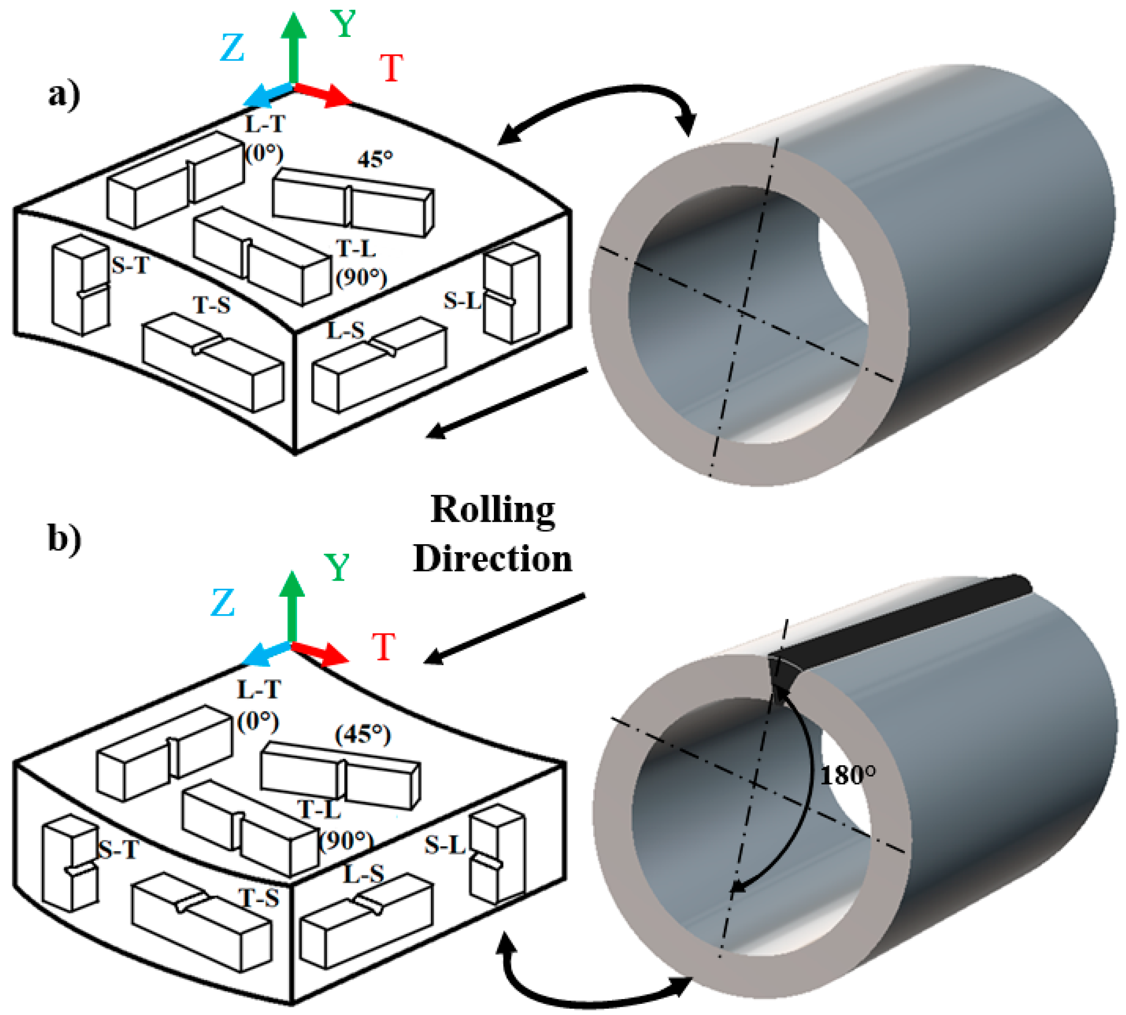
2.1. CVN Impact Testing

The EWR pipe used in this experiment had a wall thickness of 25.4 mm and a diameter of 914.4 mm. For the SMLS pipe, the wall thickness was 25.4 mm, and the diameter was 406.4 mm. Both pipes followed the requirements described in API 5L for PSL 2 steels [22]. Taking the rolling direction as a reference, the samples were manufactured from all representative orientations at 45° from the rolling direction. The name of each sample is listed in Table 1 according to the direction in which it was obtained. Three Charpy specimens were obtained for each working condition. Figure 1a,b present the Charpy specimens in the pipeline considering the rolling directions of the SMLS and ERW pipelines, respectively. These specimens were used according to the ASTM E23 standard [56] in Charpy model 74 with a capacity of 0.0–274 lb-ft. Standard Charpy specimens measuring 10 × 10 × 55 mm were employed. Tests were performed at room temperature. In the ASTM E23 standard, there are subsized specimens (from 2.5 × 10 × 55 mm to 10 × 10 × 55 mm). Because of the dimensions of the pipes analyzed, a wall thickness of 25.4 mm and standard-sized specimens were chosen. To estimate the ductile and brittle fracture areas, the processes indicated in the ASTM E23 standard were followed.

2.2. Welding Charpy Impact Specimens

Since several specimens did not reach the length of the Charpy specimens (55 mm), larger specimens were made to achieve the required length using extensions jointed by welding. The specimens were joined via the Tungsten inert gas (TIG) welding process using an in-verter machine (ESAB, Goteborg, Sweden) with tungsten electrodes (3/32-inch diameter) (ESAB, Goteborg, Sweden) and a current intensity of 90 Amperes. The welded specimens for the Charpy test are illustrated in Figure 2. With this process, fractures were located in the notches of the specimens, just as the literature indicates.

2.3. Microstructure, Grain Size, and Rockwell Hardness (HR)

To reveal the microstructure and to estimate the grain size, the transverse direction (plane T-S), longitudinal direction (plane L-S), and upper direction (plane L-T) were evaluated, as indicated in Figure 3. Micrographs were obtained using an optical microscope (Olympus, Center Valley, PA, USA) at 100X magnification, as indicated by ASTM E112 [57,58]. Additionally, scanning electron microscopy (SEM) (JEOL JSM-6300, JEOL, Peabody, MA, USA) was carried out to observe the fracture surfaces after the Charpy test. The Rockwell hardness C was obtained by following the ASTM E370 standard [58]. Figure 3 depicts the points on the samples where the hardness was tested.

3. Results and Discussion

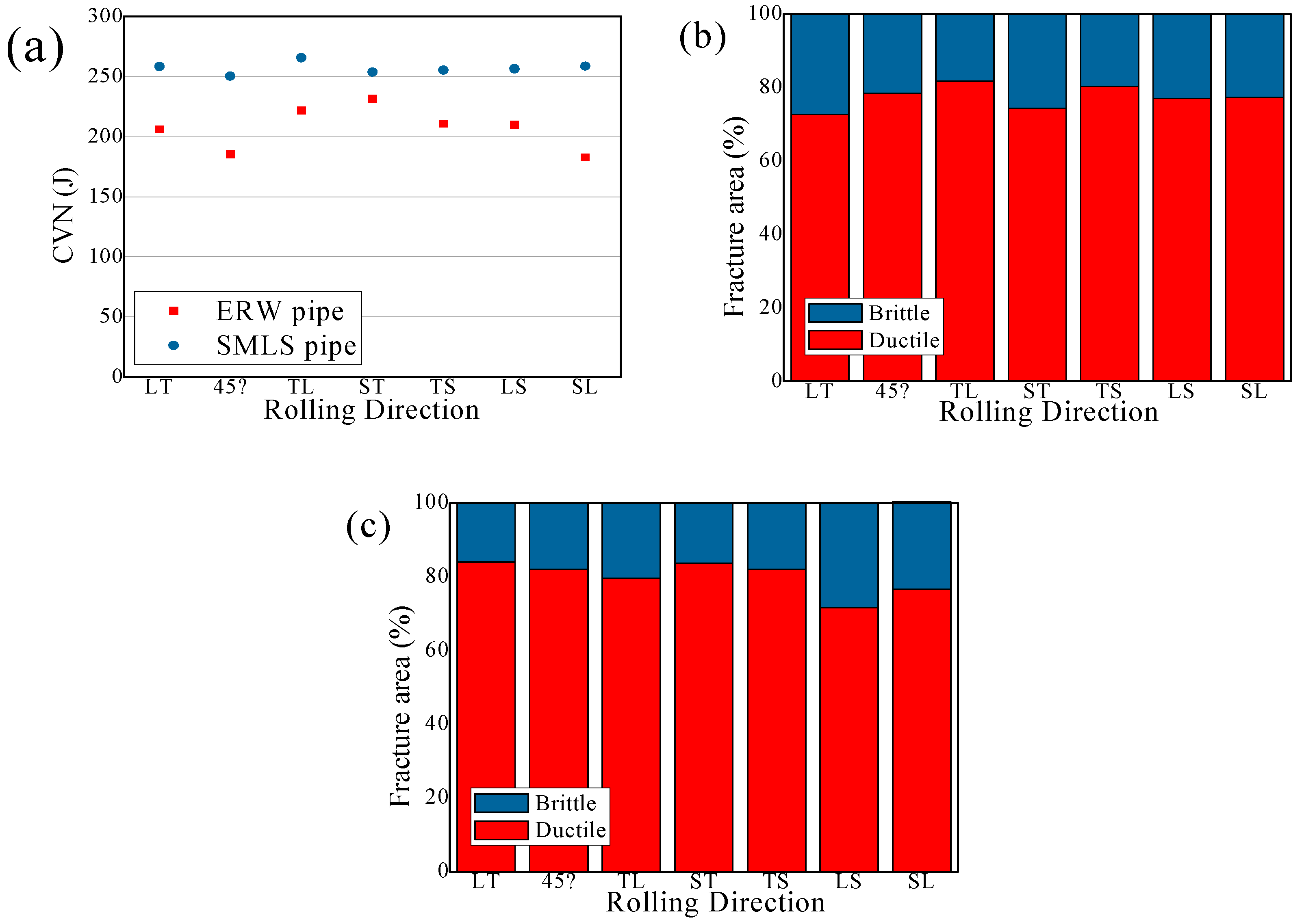
3.1. Charpy Impact Values

Table 2 shows the CVN values and ductile and brittle fracture areas, and these data are plotted in Figure 4. One can affirm that the toughness values of the steel in the SMLS pipe are higher than those of the steel in the ERW pipe for the ST, TL, TS, LS, LT, 45°, and SL directions. When comparing the Charpy values in Table 2 with other studies where the authors also used API 5L X52 welded pipe [59], it can be seen that the values reported in Table 1 are higher. Typically, it is recognized that the mechanical properties of PSL 1 pipelines are lower than those of PSL 2 pipes, and the values from the Charpy impact test are within these values, according to API standard 5L [22].
The Charpy values for all conditions are constant and homogeneous with each other (see Figure 4a). Additionally, there is not much difference for each rolling condition for the three Charpy specimens. However, they cannot be compared directly because the SMLS pipe diameter is 406.4 mm, while the ERW one is 914.4 mm. Also, ductile and brittle fracture behavior is observed for both pipelines. It can be mentioned that the ductile fracture values are higher for the SMLS pipeline compared to the ERW pipeline (see Figure 4b,c). As pointed out above, the toughness values are higher for the SMLS pipe compared to the ERW pipe.
The Charpy energy values for both pipes with respect to angle variation (TL, LT, and at 45°) have the same behavior. The Charpy energy values are higher for the TL condition, followed by the LT condition, and finally the 45° condition. While the Charpy energy values for the SMLS pipe, comparing all rolling direction conditions, are higher in the TL, SL, LT, ST, LS, TS, and 45° conditions, the Charpy energy values for the ERW pipe, comparing all rolling directions, are higher in the ST, TL, TS, LS, LT, 45°, and SL conditions. Beltran et al. [60] found that the fracture toughness values of an API X42 steel in base metal (BM) were 20% higher in the longitudinal direction than in the short transverse direction. Terán et al. [61] found that the Charpy energy values of a pipeline made of steel were highest for the longitudinal directions, and finally the circumferential direction. Different works reported Charpy values in different directions with respect to the rolling direction in pipelines, showing serious anisotropy depending on the notch direction [24,41,50] Anisotropy is an important issue in the mechanical behavior of API 5L pipelines [46,62].
For example, Ju et al. [46] reported that the Charpy values in the longitudinal direction were much lower than in the circumferential direction (by about 0.7 at room temperature). Zhu et al. [45] found that the Charpy impact data were higher for the longitudinal direction, followed by 45°, with the lowest values for the longitudinal direction. Samples parallel to the rolling direction had higher impact energy [45].
The results indicate that API 5L pipeline steel shows serious anisotropy behavior with a change in the orientation of a sample with respect to the rolling direction [27,43]. Anisotropy can arise from several factors such as chemical segregation, variation in the shape and size of grains, inclusions, and crystallographic texture [27]. Stringer-shaped inclusions are known to cause anisotropy in mechanical properties such as tensile ductility and fracture toughness [26]. Variations in grain size and grain shape along different directions can also cause anisotropy [32]. Another study [46] suggested, based on an analysis of texture intensities, that the anisotropy of toughness at room temperature might be attributed to the variation in the volume fraction of the {110} plane, with an angle to the circumferential direction.

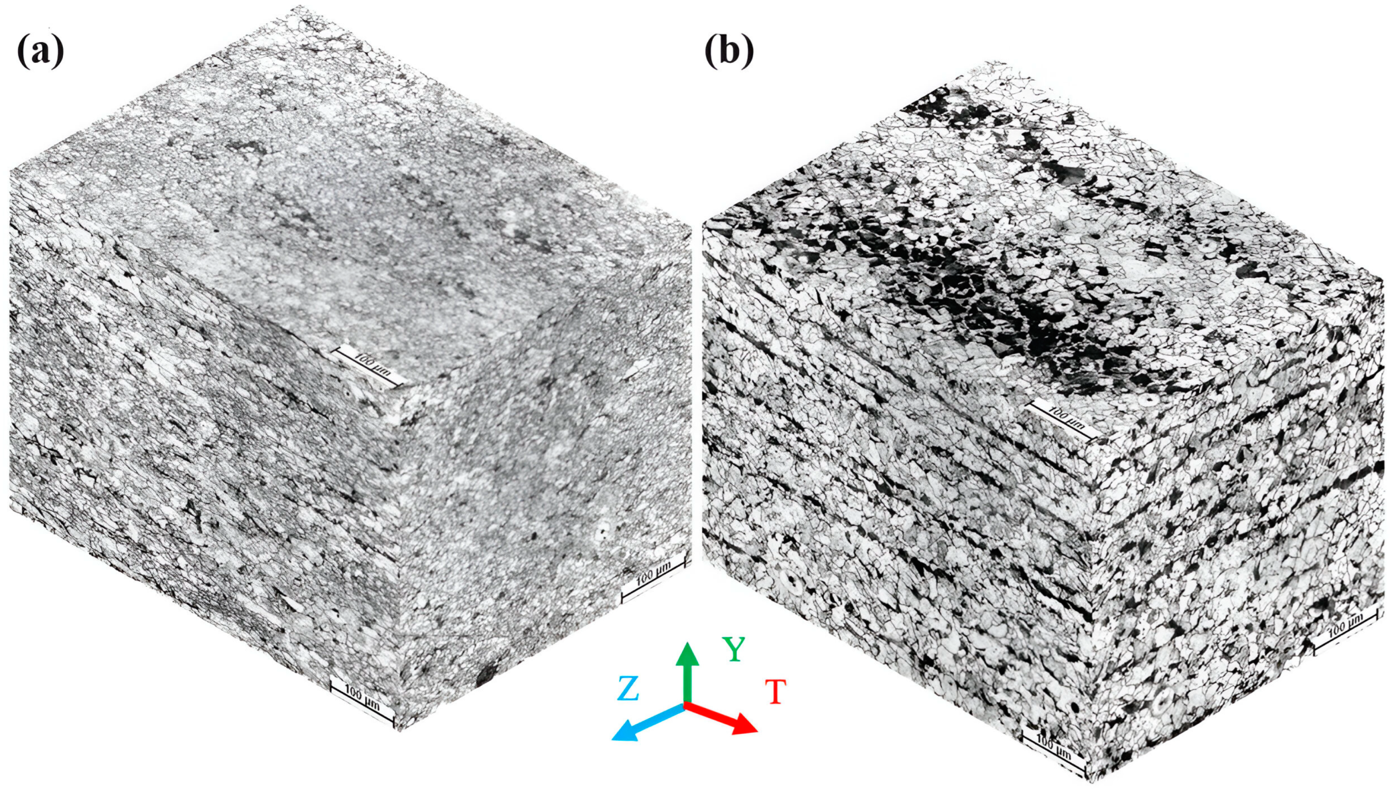
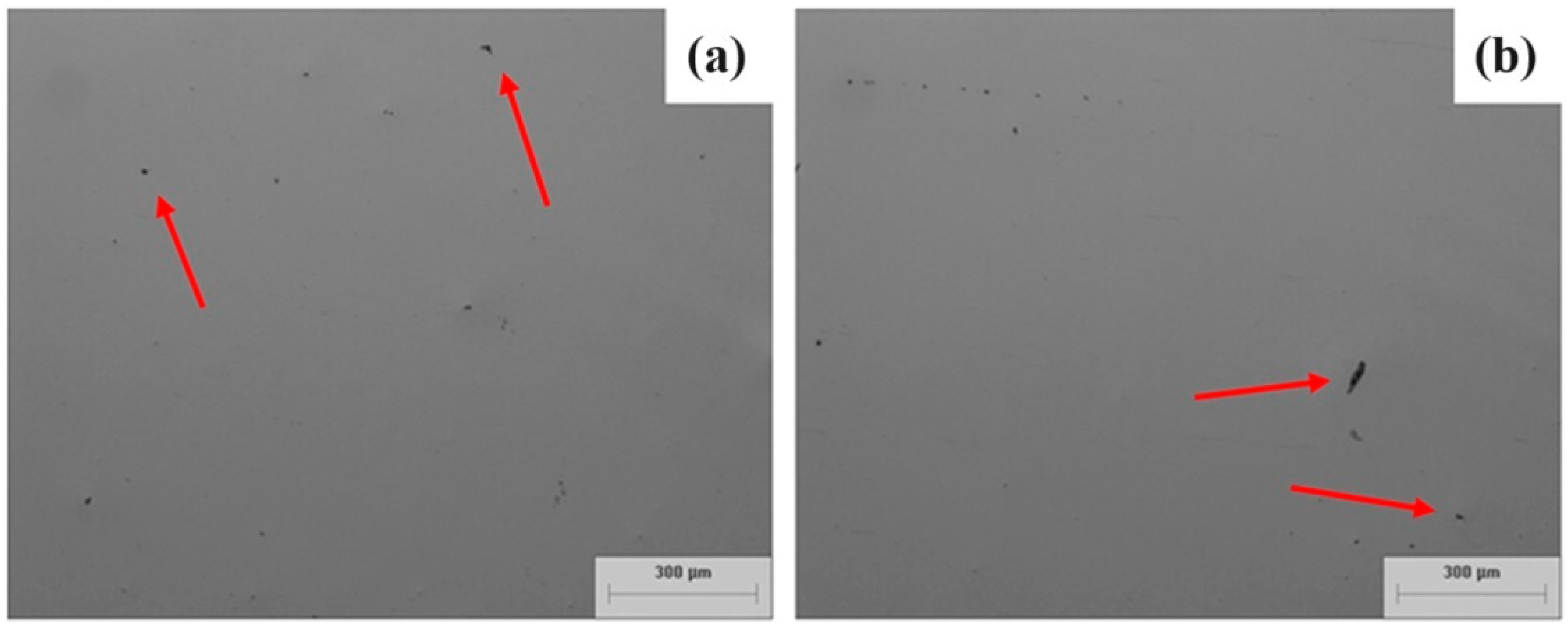
3.2. Microstructures Obtained and HR Values

Figure 5 shows micrographs of the ERW and SMLS pipes for the LT, LS, and TS planes. The mechanical properties of API 5L pipelines depend on the microstructural characteristics of the pipelines [63,64,65]. One can see in the photographs that the ERW pipe is more uniform for the ST, TL, TS, LS, LT, 45°, and SL directions. This is because, during the manufacturing process, in the rolling stages, the grains were distributed along the rolling directions. For SMLS pipes, the processes are carried out using a plug mill, mandrel mill, and pilger mill. The grain size value for the welded pipeline is 10.3 μm, while for the SMLS pipelines the grain size is about 11 μm. Here, the grains are smaller, scattered, and not homogeneous compared to the ERW pipe grains. As we can see in Figure 5, the microstructures correspond to general ferrite (white) and pearlite (black) structures. The welded pipeline consists of ferritic and perlitic microstructures that are strongly elongated in the rolling direction. Jang et al. [46] reported that the microstructures and mechanical properties of steel can change during the pipe-forming process. During plastic deformation due to cold or hot work, grains are elongated in the direction of the applied stress. Therefore, the ferrite grain size varies in different directions, resulting in anisotropy in mechanical properties [28,32]. It is observed that grains of perlite and ferrite are usually oriented in the directions of lamination. This behavior is known as banding. Banding is more visible in the laminate direction than in the transverse direction [66]. In the 45° direction, a combination of microstructures is observed between the longitudinal and transverse directions. During the manufacture of ERW pipelines, thermal treatments of quenching and tempering can be applied [26]. For seamless pipes, two treatment methods are employed: normalizing, and quenching and temping treatment. With these treatments, ferrite, pearlite, bainite, and martensite can be obtained. Figure 6a,b show non-metallic inclusions in the ERW pipeline in plane T-S and plane L-S, respectively. For the SMLS pipeline, it was more difficult to find non-metallic inclusions due to the elongated microstructures.
In the context of inclusions, manganese sulfide and silicates become elongated during the rolling process, and hence contribute to mechanical anisotropy [24]. It can be said that non-metallic inclusions affect the mechanical properties of pipelines [67,68,69].
The Rockwell hardness C values of these two pipes are reported in Table 3. It can be said that the Rockwell hardness C hardness values of the ERW pipe are the same for all three measured directions. Sung [24] determined that when anisotropy occurs in seam-welded pipelines, the hardness values are the same and the hardness is not affected by the anisotropy. However, in the SMLS pipe, a small variation in the results can be observed. It is present, as mentioned above, because the grains are more dispersed, smaller, and not homogeneous. Higher values are obtained in the transverse direction (plane T-S), followed by the upper plane (plane L-T), and finally the longitudinal direction (plane L-S). This behavior is because of mechanical properties, such as hardness, Charpy values, and yield stress, which depend on the rolling directions of the pipelines. For the SMLS pipe, the ferrite and perlite grains are smaller compared to the ERW pipe, and as a result, this pipe has higher hardness and Charpy values. According to a previous study [66], there are higher grain size values in the longitudinal direction compared to the transverse direction, resulting in lower mechanical properties.

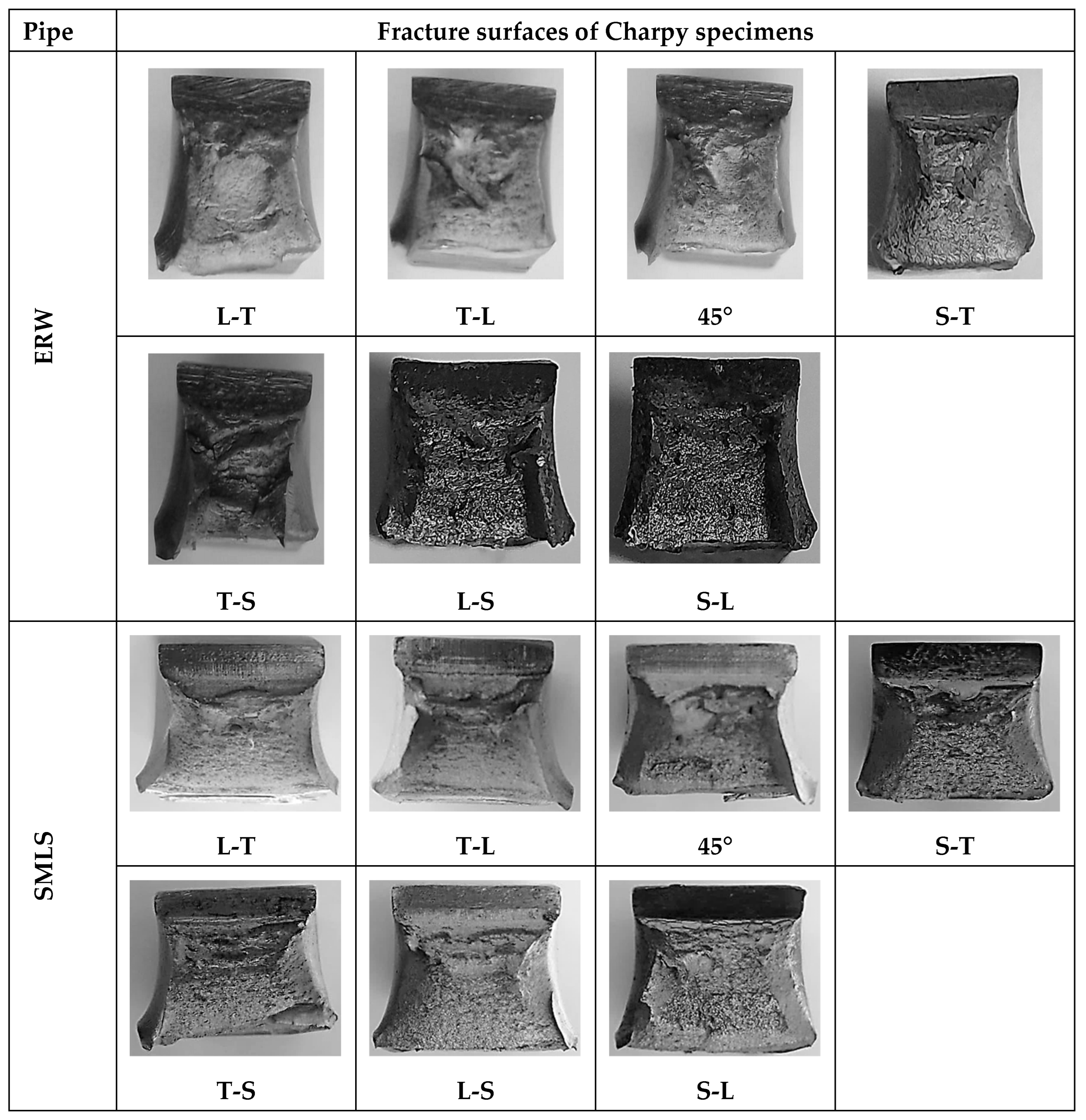
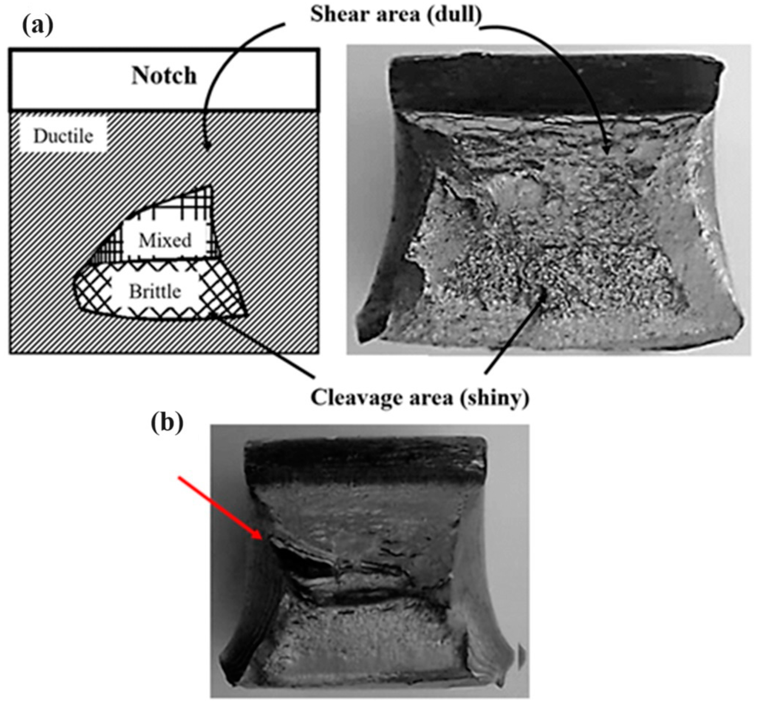
3.3. Fracture Surfaces of Charpy Specimens

Figure 7 shows a comparison of Charpy specimens between a specimen that did not need extension and one with an extension welded using the TIG process. For the latter, fractures occurred within the notch and in the metal tested. The TIG welding procedure was appropriate to obtain the standard specimen dimensions. This was confirmed by the results obtained using the Charpy values described above. Figure 8 confirm that surfaces present high plastic deformation. Because the Charpy specimens were tested at room temperature, the specimens were presumably in the upper range of the ductile-to-brittle transition (DBT) temperature. Therefore, the fractured Charpy impact specimens exhibited ductile behavior. The specimens were reported as “non-fractured test tubes” and averaged with the other Charpy specimens. The CVN results were below 80% of the capacity of the Charpy impact test, as stated in ASTM E23 [56].
Figure 8 shows all fracture surfaces of the Charpy specimens for the ERW and SMLS pipes. It can be said that all specimens had ductile behavior. This was because the tests were performed at room temperature, considering that API 5L X52 steel shows real toughness behavior in this condition. It can be said that for all fracture surfaces of the Charpy specimens, ductile zones, and brittle zones appeared, and small ductile and brittle (mixed) zones could be observed (see Figure 9a). Also, a common defect that could be found was delaminations on all ERW pipe fracture surfaces, mainly for the TL, TS, and LS conditions (see Figure 9b). Delaminations are generated during the rolling of a pipeline, and can occur on ferrite–perlite sections or along perlite bands. It has been reported that they decrease the mechanical properties in the transverse direction [66]. Joo et al. [48] reported delaminations in API X80 steel in the TL, LT, and LS directions.
Figure 10 presents fracture surfaces using a scanning electron microscope. It is interesting to note that all specimens have a ductile mechanism with high toughness values. Ductile fracture indicates a border on a specimen with characteristic lusterless and dark features [70]. It is observed that the specimens have areas of shear and cleavage. In addition, fibrous fracture, shear lips, microvoid coalescence, dimpled surfaces, main cracks, and secondary cracks are presented [71,72,73]. A common feature is that the generation of secondary cracks is also indicative of high absorbed energy [74].

4. Conclusions

Toughness values and ductile fracture are higher for the SMLS pipeline compared to the ERW pipeline. The CVN values of the SMLS pipe are greater for all rolling direction conditions (TL, SL, LT, ST, LS, TS, and 45°). Moreover, the CVN data of the ERW pipe are higher in the ST, TL, TS, LS, LT, 45°, and SL directions. The microstructures of the two pipelines studied in this paper (ERW and SMLS) contain ferrite and perlite elongated in the rolling direction. For the ERW pipe, the grain size is 10.3 μm. For the SMLS pipe, the grain size is about 11 μm. For the ERW pipe, metallurgical factors such as non-metallic inclusions are observed. Anisotropic behavior is important to the mechanical properties of pipeline steels and depends on the rolling direction of a pipeline. Mechanical properties such as toughness and hardness depend on the microstructural characteristics and rolling direction of seam-welded pipelines. The fracture surfaces of the Charpy specimens presented highly ductile behavior. On the surfaces of the Charpy specimens, ductile zones, brittle zones, and mixed ductile and brittle zones were observed. In addition, delaminations could be found on the Charpy fracture surfaces, which decreased the mechanical properties of the pipelines. Fibrous fractures, shear lips, microvoids, dimples, and cracks were observed on the fracture surfaces. These defects are typical of plastic deformation during Charpy tests at room temperature. The results in this work serve to know the mechanical behavior of two steels in the transport of hydrocarbons worldwide, and to complement the values, it is recommended to perform Charpy tests at low temperatures, in order to determine ductile-to-brittle transition curve.

Author Contributions

Conceptualization, S.I.C.-C. and G.T.M.; methodology, S.I.C.-C. and G.T.M.; software, J.C.V.; validation, S.I.C.-C., G.T.M. and D.A.-H.; formal analysis, D.A.-H.; investigation, N.E.G.-A. and E.T.-S.; resources, S.I.C.-C. and G.T.M.; data curation J.C.V. and A.C.-T.; writing—original draft preparation, S.I.C.-C. and G.T.M.; writing—review and editing, J.C.V.; visualization, A.C.-T. and E.T.-S.; supervision, S.I.C.-C. and G.T.M.; project administration, J.C.V. and N.E.G.-A.; funding acquisition, S.I.C.-C. and G.T.M. All authors have read and agreed to the published version of the manuscript.

Funding

This work was supported by research grant 20221234 of IPN in Mexico.

Institutional Review Board Statement

Not applicable.

Informed Consent Statement

Not applicable.

Data Availability Statement

The data that support the finding of this study are available from the corresponding author upon reasonable request.

Acknowledgments

The authors thank ESIQIE-IPN and CONAHCYT for the facilities to perform this research.

Conflicts of Interest

The authors declare no conflict of interest.

References

  1. Valois, B.-F. Hydrocarbons Will Continue to Play a Relevant Role in the World’s Energy Matrix. Available online: https://www.bnamericas.com/en/interviews/hydrocarbons-will-continue-to-play-a-relevant-role-in-the-worlds-energy-matrix (accessed on 28 December 2023).
  2. Pipeline and Hazardous Materials Safety Administration. In Annual Report Mileage for Hazardous Liquid or Carbon Dioxide Systems. Available online: https://www.phmsa.dot.gov/data-and-statistics/pipeline/annual-report-mileage-hazardous-liquid-or-carbon-dioxide-systems (accessed on 28 December 2023).
  3. Xiao, R.; Zayed, T.; Meguid, M.A.; Sushama, L. Understanding the Factors and Consequences of Pipeline Incidents: An Analysis of Gas Transmission Pipelines in the US. Eng. Fail. Anal. 2023, 152, 107498. [Google Scholar] [CrossRef]
  4. Biezma, M.V.; Andrés, M.A.; Agudo, D.; Briz, E. Most Fatal Oil & Gas Pipeline Accidents through History: A Lessons Learned Approach. Eng. Fail. Anal. 2020, 110, 104446. [Google Scholar] [CrossRef]
  5. Velázquez, J.C.; Caleyo, F.; Valor, A.; Venegas, V.; Espina-Hernández, J.H.; Hallen, J.M.; López, M.R. Study Helps Model Buried Pipeline Pitting Corrosion. Oil Gas J. 2009, 107, 64–73. [Google Scholar]
  6. Papavinasam, S. Corrosion Control in the Oil and Gas Industry, 1st ed.; Gulf Professional Publishing, Ed.; Elsevier: Houston, TX, USA, 2014. [Google Scholar] [CrossRef]
  7. Rybakov, A.A.; Filipchuk, T.N.; Goncharenko, L.V. Cracks in welded joints of large diameter pipes and measures for their prevention. Paton Weld. J. 2013, 4, 15–20. [Google Scholar]
  8. Cao, J.; Ma, W.; Pang, G.; Wang, K.; Ren, J.; Nie, H.; Dang, W.; Yao, T. Failure Analysis on Girth Weld Cracking of Underground Tee Pipe. Int. J. Press. Vessel. Pip. 2021, 191, 104371. [Google Scholar] [CrossRef]
  9. Xue, H.B.; Cheng, Y.F. Characterization of Inclusions of X80 Pipeline Steel and Its Correlation with Hydrogen-Induced Cracking. Corros. Sci. 2011, 53, 1201–1208. [Google Scholar] [CrossRef]
  10. Liu, Z.Y.; Li, X.G.; Du, C.W.; Lu, L.; Zhang, Y.R.; Cheng, Y.F. Effect of Inclusions on Initiation of Stress Corrosion Cracks in X70 Pipeline Steel in an Acidic Soil Environment. Corros. Sci. 2009, 51, 895–900. [Google Scholar] [CrossRef]
  11. Pourazizi, R.; Mohtadi-Bonab, M.A.; Szpunar, J.A. Role of Texture and Inclusions on the Failure of an API X70 Pipeline Steel at Different Service Environments. Mater. Charact. 2020, 164, 110330. [Google Scholar] [CrossRef]
  12. Cosham, A.; Hopkins, P.; Leis, B. Crack-Like Defects in Pipelines: The Relevance of Pipeline-Specific Methods and Standards. In Volume 2: Pipeline Integrity Management, Proceedings of the 2012 9th International Pipeline Conference, Calgary, AB, Canada, 24–28 September 2012; American Society of Mechanical Engineers: New York, NY, USA, 2012; pp. 713–726. [Google Scholar] [CrossRef]
  13. Kawasaki, T.; Nakanishi, S.; Sawaki, Y.; Hatanaka, K.; Yokobori, T. Fracture Toughness and Fatigue Crack Propagation in High Strength Steel from Room Temperature to −180 °C. Eng. Fract. Mech. 1975, 7, 465–472. [Google Scholar] [CrossRef]
  14. Robinson, J.N.; Tuck, C.W. The Relationship between Microstructure and Fracture Toughness for a Low-Alloy Steel. Eng. Fract. Mech. 1972, 4, 377–392. [Google Scholar] [CrossRef]
  15. Li, H.F.; Duan, Q.Q.; Zhang, P.; Zhou, X.H.; Wang, B.; Zhang, Z.F. The Quantitative Relationship between Fracture Toughness and Impact Toughness in High-Strength Steels. Eng. Fract. Mech. 2019, 211, 362–370. [Google Scholar] [CrossRef]
  16. Leis, B.N.; Eiber, R.J.; Carlson, L.; Gilroy-Scott, A. Relationship between Apparent (Total) Charpy Vee-Notch Toughness and the Corresponding Dynamic Crack-Propagation Resistance. In Volume 2: Design and Construction; Pipeline Automation and Measurement; Environmental Issues; Rotating Equipment Technology, Proceedings of the 1998 2nd International Pipeline Conference, Calgary, AB, Canada, 7–11 June 1998; American Society of Mechanical Engineers: New York, NY, USA, 1998; pp. 723–731. [Google Scholar] [CrossRef]
  17. Zhen, Y.; Jiao, Z.; Cao, Y.; Niu, R. Unified Correlation of Constraints with Crack Arrest Toughness for High-Grade Pipeline Steel. Int. J. Press. Vessel. Pip. 2021, 193, 104454. [Google Scholar] [CrossRef]
  18. Terán, G.; Capula-Colindres, S.; Velázquez, J.C.; Angeles-herrera, D.; Súchil, O.G. Mechanical resitance of stepped laminations defects in a welded section of oil and gas pipeline: A finite element analysis. J. Braz. Soc. Mech. Sci. Eng. 2018, 41, 504. [Google Scholar] [CrossRef]
  19. Mahajan, D.; Tan, K.; Venkatesh, T.; Kileti, P.; Clayton, C.R. Hydrogen Blending in Gas Pipeline Networks—A Review. Energies 2022, 15, 3582. [Google Scholar] [CrossRef]
  20. Nykyforchyn, H.; Zvirko, O.; Dzioba, I.; Krechkovska, H.; Hredil, M.; Tsyrulnyk, O.; Student, O.; Lipiec, S.; Pala, R. Assessment of Operational Degradation of Pipeline Steels. Materials 2021, 14, 3247. [Google Scholar] [CrossRef] [PubMed]
  21. Zvirko, O.; Tsyrulnyk, O.; Lipiec, S.; Dzioba, I. Evaluation of Corrosion, Mechanical Properties and Hydrogen Embrittlement of Casing Pipe Steels with Different Microstructure. Materials 2021, 14, 7860. [Google Scholar] [CrossRef] [PubMed]
  22. American Petroleum Institute. API 5L Specifications for Line Pipe; American Petroleum Institute: Houston, TX, USA, 2007. [Google Scholar]
  23. Kyriakides, S.; Corona, E. Mechanics of Offshore Pipelines: Buckling and collapse Volume I; Elsevier: Amsterdam, The Netherlands, 2007. [Google Scholar] [CrossRef]
  24. Sung, M.J. Anisotropy of Charpy Properties in Linepipe Steels; Pohang University of Science and Technology: Pohang, Republic of Korea, 2012. [Google Scholar]
  25. Advantages of Seamless Steel Pipes. Available online: https://milfit.com.tr/en/advantages-of-seamless-steel-pipes/ (accessed on 4 March 2024).
  26. Braestrup, M.; Andersen, J.; Andersen, L.; Bryndum, M.; Nielsen, N. Design and Installation of Marine Pipelines; Blackwell Publishing: Oxford, UK, 2005. [Google Scholar]
  27. Alkazraji, D. A Quick Guide to Pipeline Engineering; Woodhead Publishing Limited and Matthews Engineering Training Ltd.: Cambridge, UK, 2008. [Google Scholar]
  28. Toma, D.; Rohden, V.; Kubla, G. Development of API X70-X80 Grades Heavy-Wall Seamless Pipes with Low Temperature Toughness. In All Days, Proceedings of the OTC Brasil, Rio de Janeiro, Brazil, 4–6 October 2011; OTC: Hollister, MO, USA, 2011. [Google Scholar] [CrossRef]
  29. Winston Revie, R. Oil and Gas Pipelines: Integrity and Safety Handbook; Wiley: Hoboken, NJ, USA, 2015. [Google Scholar]
  30. Nagayama, H.; Hamada, M.; Mruczek, M.F.; Vickers, M.; Hisamune, N.; Fukuba, T.; Arredondo, A. Development of Welding Procedures for X90-Grade Seamless Pipes for Riser Applications. In Volume 3: Materials and Joining, Proceedings of the OTC Brasil, Rio de Janeiro, Brazil, 4–6 October 2011; American Society of Mechanical Engineers: New York, NY, USA, 2012; pp. 9–16. [Google Scholar] [CrossRef]
  31. Batalha, R.L.; Godefroid, L.B.; de Faria, G.L.; Porcaro, R.R.; Cândido, L.C.; Trindade, V.B. Strain Ageing in Welded Joints of API5L X65Q Seamless Pipes. Weld. Int. 2017, 31, 577–582. [Google Scholar] [CrossRef]
  32. Konrad, J.; Toma, D.; Rohden, V.; Kubla, G. Heavy Wall Seamless Line Pipe X70–X80 for Sour Service Applications. In Proceedings of the 2010 8th International Pipeline Conference, ASMEDC, Calgary, AB, Canada, 27 September–1 October 2010; Volume 2, pp. 423–427. [Google Scholar] [CrossRef]
  33. Toma, D.; Harksen, S.; Niklasch, D.; Mahn, D.; Koka, A. Development of X90 and X100 Steel Grades for Seamless Linepipe Products. In Volume 3: Materials and Joining; Risk and Reliability, 2014 10th International Pipeline Conference, Calgary, AB, Canada, 29 September–3 October 2014; American Society of Mechanical Engineers: New York, NY, USA, 2014. [Google Scholar] [CrossRef]
  34. Bruns, C.; Wiebe, J.; Niklasch, D.; Mahn, D.; Schmidt, T. Impact of Welding Parameters on Weld Seam Properties of Seamless X80 Linepipe Steel Grade. In Volume 3: Materials and Joining; Risk and Reliability, 2014 10th International Pipeline Conference, Calgary, AB, Canada, 29 September–3 October 2014; American Society of Mechanical Engineers: New York, NY, USA, 2014. [Google Scholar] [CrossRef]
  35. Velázquez, J.C.; Caleyo, F.; Hallen, J.M.; Romero-Mercado, O.; Herrera-Hernandez, H. Probabilistic Analysis of Different Methods Used to Compute the Failure Pressure of Corroded Steel Pipelines. Int. J. Electrochem. Sci. 2013, 2013, 11356–11370. [Google Scholar] [CrossRef]
  36. Nonn, A.; Wessel, W.; Schimidt, T. Application of Finite Element Analysis for Assessment of Fracture Behavior of Modern High Toughness Seamless Pipeline Steel. In Proceedings of the Twenty-third International Offshore and Polar Engineering, Anchorage, AK, USA, 30 June–5 July 2013; pp. 670–677. [Google Scholar]
  37. Hasenhutl, A.; Erdelen, M.P.; Schimidt, M.; Niklasch, D. Drop Weight Tear Testing of Seamless Linepipe. In Proceedings of the Twenty-fist International Offshore and Polar Engineering Conference 2011, Maui, HI, USA, 19–24 June 2011; p. 230. [Google Scholar]
  38. Scherf, S.; Harksen, S.; Hojda, R.; Lang, P.; Schütz, M. Advanced High Toughness X100 Seamless Pipes with a New Specialized Alloying Concept for Arctic Offshore Structurals Applications. In Proceedings of the 27th International Ocean and Polar Engineering Conference, San Francisco, CA, USA, 25–30 June 2017. [Google Scholar]
  39. Wu, Q.; Zhang, Z.; Liu, Y.; Chen, H. Strain Aging Behaviour of Cu-Containing Microalloyed Low Carbon Seamless Pipeline Steel. Mater. Sci. Technol. 2017, 33, 72–76. [Google Scholar] [CrossRef]
  40. Godefroid, L.B.; Sena, B.M.; da Trindade Filho, V.B. Evaluation of Microstructure and Mechanical Properties of Seamless Steel Pipes API 5L Type Obtained by Different Processes of Heat Treatments. Mater. Res. 2017, 20, 514–522. [Google Scholar] [CrossRef]
  41. Zhongqiu, L.; Jian, F.; Yong, Z.; Zexi, Y. Influence of Quenching On-Line on Properties of X70 Steel for Sour Service Seamless Pipe. Energy Procedia 2012, 16, 444–450. [Google Scholar] [CrossRef]
  42. Mohrbacher, H. Production-concepts-of-niobium-microalloyed-structural-hollows-by-seamless-pipe-rolling. In Proceedings of the Value-added Niobium Microalloyed Construction Steels Symposium, Singapore, January 2012; pp. 191–211. Available online: https://www.niobelcon.com/NiobelCon/resources/PRODUCTION-CONCEPTS-OF-NIOBIUM-MICROALLOYED-STRUCTURAL-HOLLOWS-BY-SEAMLESS-PIPE-ROLLING.pdf (accessed on 28 December 2023).
  43. Ghosh, A.; Modak, P.; Dutta, R.; Chakrabarti, D. Effect of MnS Inclusion and Crystallographic Texture on Anisotropy in Charpy Impact Toughness of Low Carbon Ferritic Steel. Mater. Sci. Eng. A 2016, 654, 298–308. [Google Scholar] [CrossRef]
  44. Yang, X.-L.; Xu, Y.-B.; Tan, X.-D.; Wu, D. Relationships among Crystallographic Texture, Fracture Behavior and Charpy Impact Toughness in API X100 Pipeline Steel. Mater. Sci. Eng. A 2015, 641, 96–106. [Google Scholar] [CrossRef]
  45. Zhu, L.; Wang, Y.; Li, J.; Chen, H.; He, X.; Han, X. Study on Correlation of Orientation and Impact Properties in HTP Line-Pipe Steel. In Proceedings of the 2008 7th International Pipeline Conference, ASMEDC, Calgary, AB, Canada, 29 September–3 October 2008; Volume 3, pp. 11–14. [Google Scholar] [CrossRef]
  46. Ju, J.-B.; Lee, J.-S.; Jang, J. Fracture Toughness Anisotropy in a API Steel Line-Pipe. Mater. Lett. 2007, 61, 5178–5180. [Google Scholar] [CrossRef]
  47. García, O.L.; Petrov, R.H.; Bae, J.H.; Kestens, L.A.I.; Kang, K.B. Microstructure—Texture Related Toughness Anisotropy of API-X80 Pipeline Steel. Adv. Mat. Res. 2006, 15–17, 840–845. [Google Scholar] [CrossRef]
  48. Joo, M.S.; Suh, D.-W.; Bae, J.H.; Bhadeshia, H.K.D.H. Role of Delamination and Crystallography on Anisotropy of Charpy Toughness in API-X80 Steel. Mater. Sci. Eng. A 2012, 546, 314–322. [Google Scholar] [CrossRef]
  49. Joo, M.S.; Suh, D.-W.; Bae, J.H.; Sanchez Mouriño, N.; Petrov, R.; Kestens, L.A.I.; Bhadeshia, H.K.D.H. Experiments to Separate the Effect of Texture on Anisotropy of Pipeline Steel. Mater. Sci. Eng. A 2012, 556, 601–606. [Google Scholar] [CrossRef]
  50. Yang, X.-L.; Xu, Y.-B.; Tan, X.-D.; Wu, D. Influences of Crystallography and Delamination on Anisotropy of Charpy Impact Toughness in API X100 Pipeline Steel. Mater. Sci. Eng. A 2014, 607, 53–62. [Google Scholar] [CrossRef]
  51. Gravel, A.J.; Layland, S.; Corley, J. Case study in the use of forensic history in matters involving pipeline ruptures. In Oil Spill Environmental Forensics Case Studies; Stout, S.A., Wang, Z., Eds.; Butterworth-Heinemann: Oxford, UK, 2018; pp. 499–543. [Google Scholar] [CrossRef]
  52. Aranas, C., Jr.; He, Y.; Podlesny, M. Magnetic Barkhausen noise characterization of two pipeline steels with unknown history. Mater. Charact. 2018, 146, 243–257. [Google Scholar] [CrossRef]
  53. Terán, G.; Capula-Colindres, S.; Velázquez, J.C.; Fernández-Cueto, M.J.; Ángeles-Herrera, D.; Herrera-Hernández, H. Failure pressure estimations for pipes with combined corrosion defects on the external surface: A comparative study. Int. J. Electrochem. Sci. 2017, 12, 10152–10176. [Google Scholar] [CrossRef]
  54. US DOT. Pipeline and Hazardous Materials Safety Administration. Available online: https://www.phmsa.dot.gov/ (accessed on 11 March 2024).
  55. Ossai, C.I.; Boswell, B.; Davies, I.J. Pipelines failures in corrosive environments-A conceptual analysis of trend and effects. Eng. Fail. Anal. 2015, 53, 36–58. [Google Scholar] [CrossRef]
  56. ASTM E23-2018; Standard Test Methods for Notched Impact Testing of Metallic Materials. ASTM International: West Conshohocken, PA, USA, 2018.
  57. ASTM E112-13; Standard Test Methods for Determining Average Grain Size. ASTM International: Conshohocken, PA, USA, 2013.
  58. ASTM E370; Standard Test Methods and Definitions for Mechanical Testing of Steel Products. ASTM International: Conshohocken, PA, USA, 2020.
  59. Moeinifar, S. Influence of Anisotropy Behavior in UOE Process for X80 Micro Alloy Steel. Adv. Mat. Res. 2011, 287–290, 2161–2164. [Google Scholar] [CrossRef]
  60. Beltrán-Zuñiga, M.A.; González-Velázquez, J.L.; Rivas-Lopéz, D.I.; Hernández-Santiago, F.; Dorantes-Rosales, H.J.; Lopéz-Hirata, V.M. Determination of fracture toughness in the short transverse direction of low carbon steel pipes by compact-tesion specimens completed by welded attachments. Eng. Fract. Mech. 2019, 222, 106711. [Google Scholar] [CrossRef]
  61. Teran, G.; Capula-Colindres, S.; Chavez, F.; Velázquez, J.C.; Torres-Santillán; Angeles-Herrera, D.; Goiz, O. Charpy impact toughness in all direcitons with respect to the rolling direction of API X52 pipeline steel. MRS Adv. 2022, 7, 1022–1027. [Google Scholar] [CrossRef]
  62. Petrov, R.H.; García, O.L.; Mulders, J.J.L.; Reis, A.C.C.; Bae, J.H.; Kestens, L.; Houbaert, Y. Three Dimensional Microstructure–Microtexture Characterization of Pipeline Steel. Mater. Sci. Forum 2007, 550, 625–630. [Google Scholar] [CrossRef]
  63. Shin, S.Y.; Hwang, B.; Lee, S.; Kim, N.J.; Ahn, S.S. Correlation of Microstructure and Charpy Impact Properties in API X70 and X80 Line-Pipe Steels. Mater. Sci. Eng. A 2007, 458, 281–289. [Google Scholar] [CrossRef]
  64. Wang, W.; Shan, Y.; Yang, K. Study of High Strength Pipeline Steels with Different Microstructures. Mater. Sci. Eng. A 2009, 502, 38–44. [Google Scholar] [CrossRef]
  65. ASTM E1268; Standard Practice for Assessing the Degree of Banding or Orientation of Microstructures. ASTM International: Conshohocken, PA, USA, 2019.
  66. Terán-Guillén, J. Evaluación de La Tenacidad a La Fractura En La Dirección Corta de Tubería de Conducción de Hidrocarburos. Ph.D. Thesis, Instituto Politecnico Nacional, Mexico City, Mexico, 2007. [Google Scholar]
  67. Angeles-Herrera, D.; Albiter-Hernández, A.; Cuamatzi-Meléndez, R.; de Morales-Ramirez, A.J. Influence of Non-Metallic Inclusions on the Fracture-Toughness Properties on the Longitudinal Welding of an API 5L Steel Pipeline. J. Test Eval. 2017, 45, 20150061. [Google Scholar] [CrossRef]
  68. Angeles-Herrera, D.; Albiter, A.; Cuamatzi-Meléndez, R.; Terán, G.; Ochoa-Ruiz, G. Fracture-Toughness and Fatigue Crack Growth Evaluation in the Transversal Direction of the Longitudinal Weld of an API X52 Steel Pipeline. J. Test Eval. 2018, 46, 20170068. [Google Scholar] [CrossRef]
  69. Tervo, H.; Kaijalainen, A.; Pikkarainen, T.; Mehtonen, S.; Porter, D. Effect of Impurity Level and Inclusions on the Ductility and Toughness of an Ultra-High-Strength Steel. Mater. Sci. Eng. A 2017, 697, 184–193. [Google Scholar] [CrossRef]
  70. Park, T.C.; Kim, B.S.; Son, J.H.; Yeo, Y.K. A New Fracture Analysis Technique for Charpy Impact Test Using Image Processing. Korean J. Met. Mater. 2021, 59, 61–66. [Google Scholar] [CrossRef]
  71. Zong, C.; Zhu, G.; Mao, W. Effect of Crystallographic Texture on the Anisotropy of Charpy Impact Behavior in Pipeline Steel. Mater. Sci. Eng. A 2013, 563, 1–7. [Google Scholar] [CrossRef]
  72. Dean, S.W.; Manahan, M.P.; McCowan, C.N.; Manahan, M.P. Percent Shear Area Determination in Charpy Impact Testing. J. ASTM Int. 2008, 5, 101662. [Google Scholar] [CrossRef]
  73. Fassina, P.; Bolzoni, F.; Fumagalli, G.; Lazzari, L.; Vergani, L.; Sciuccati, A. Influence of Hydrogen and Low Temperature on Mechanical Behaviour of Two Pipeline Steels. Eng. Fract. Mech. 2012, 81, 43–55. [Google Scholar] [CrossRef]
  74. Waqas, A.; Qin, X.; Xiong, J.; Zheng, C.; Wang, H. Analysis of Ductile Fracture Obtained by Charpy Impact Test of a Steel Structure Created by Robot-Assisted GMAW-Based Additive Manufacturing. Metals 2019, 9, 1208. [Google Scholar] [CrossRef]
Figure 1. Schematic diagram showing the orientations of Charpy impact specimens concerning the rolling direction (L), long transverse direction (T), and short transverse direction (S). (a) SMLS pipe. (b) ERW pipe.
Coatings 14 00343 g001
Figure 2. Charpy impact specimen welded using the TIG process.
Coatings 14 00343 g002
Figure 3. Orientations for microstructure and hardness studies.
Coatings 14 00343 g003
Figure 4. (a) CVN impact values with respect to the rolling direction. (b) ERW pipeline. (c) SMLS pipeline.
Coatings 14 00343 g004
Figure 5. Optical micrographs of the investigated samples of API 5L X52 steel. (a) SMLS pipe. (b) ERW pipe.
Coatings 14 00343 g005
Figure 6. Non-metallic inclusions. (a) Plane T-S. (b) Plane L-S (indicated by red arrow).
Coatings 14 00343 g006
Figure 7. Fractured Charpy impact specimens. (a) Normal specimens. (b) Specimens welded using the TIG process.
Coatings 14 00343 g007
Figure 8. Fracture surfaces of Charpy impact specimens at different orientations.
Coatings 14 00343 g008
Figure 9. (a) Ductile and brittle fracture and a mixed ductile and brittle zone of a Charpy specimen. (b) Delamination in the LS direction in the ERW pipeline (indicated by red arrow).
Coatings 14 00343 g009
Figure 10. (a) Fibrous area, (b) dimples, (c) secondary cracks, and (d) enlarged view of cracks.
Coatings 14 00343 g010
Table 1. Nomenclature for samples studied and others used.
Nomenclature
CVNCharpy V-Notch impact test
ERWElectric-resistance-welded
SMLSSeamless pipeline
HRRockwell hardness
TIGTungsten inert gas
L-TLongitudinal–transverse direction
T-LTransverse–longitudinal direction
S-TShort transverse–transverse direction
T-STransverse–short transverse direction
L-SLongitudinal–short transverse direction
S-LShort transverse–longitudinal direction
PHMSAPipeline and Hazardous Materials Safety Administration
HICHydrogen-Induced Cracking
SCCStress Corrosion Cracking
SSCSulfide Stress Cracking
LSAWLongitudinal-seam submerged arc-welded pipe
SSAWSpiral submerged arc-welded pipe
UOEU-forming–O-forming Expansion
JCOJ-forming–C-forming–O-forming process
SEMScanning electron microscopy
DBTDuctile-to-brittle transition
Table 2. CVN values and ductile and brittle fracture for SMLS and ERW pipelines.
PipelinePipeline
SpecimenERWSMLSERWSMLS
JoulesJoulesDuctile Fracture Area (%)Brittle Fracture Area (%)Ductile Fracture Area (%)Brittle Fracture Area (%)
L-T-1 (0°)202.02261.8481198515
L-T-2 (0°)210.02254.9772288317
L-T-3 (0°)206.10258.4565358416
Average206.04258.4272.6627.338416
T-L-1 (90°)215.75268.7076248119
T-L-2 (90°)207.90262.8290107723
T-L-3 (90°)211.82265.4379218119
Average221.82265.6581.6618.3379.6620.33
45°-1173.58259.8772288020
45°-2197.11240.8782188416
45°-3185.50250.3781198218
Average185.39250.3778.3321.668218
S-T-1231.44253.8775258416
S-T-2228.49259.8770308812
S-T-3229.71256.4178227921
Average229.88256.7174.3325.6683.6616.33
T-S-1209.86258.8682188515
T-S-2211.82252.0381198119
T-S-3210.85255.4478228020
Average210.84255.4480.3319.668218
L-S-1205.94253.0077236535
L-S-2213.78260.8678227426
L-S-3209.76255.9376247624
Average209.82256.59772371.6628.33
S-L-1165.73256.9374267723
S-L-2200.05260.9377237525
S-L-3182.49258.1481197822
Average182.75258.6677.3322.6676.6623.66
Table 3. HR values of ERW and SMLS pipelines.
Direction Pipe
ERWSMLS
Upper (Plane L-T)176.589.0
277.089.5
376.587.5
average76.688.6
Longitudinal (Plane L-S)175.585.0
277.085.05
376.085.0
average76.185.8
Transverse (Plane T-S)177.090.0
276.090.0
377.087.0
average76.689.0
Disclaimer/Publisher’s Note: The statements, opinions and data contained in all publications are solely those of the individual author(s) and contributor(s) and not of MDPI and/or the editor(s). MDPI and/or the editor(s) disclaim responsibility for any injury to people or property resulting from any ideas, methods, instructions or products referred to in the content.

